WO2011125734A1 - 非水電解液二次電池用電極板、非水電解液二次電池、電池パック、および非水電解液二次電池用電極板の製造方法 - Google Patents
非水電解液二次電池用電極板、非水電解液二次電池、電池パック、および非水電解液二次電池用電極板の製造方法 Download PDFInfo
- Publication number
- WO2011125734A1 WO2011125734A1 PCT/JP2011/058002 JP2011058002W WO2011125734A1 WO 2011125734 A1 WO2011125734 A1 WO 2011125734A1 JP 2011058002 W JP2011058002 W JP 2011058002W WO 2011125734 A1 WO2011125734 A1 WO 2011125734A1
- Authority
- WO
- WIPO (PCT)
- Prior art keywords
- active material
- electrode plate
- material layer
- electrolyte secondary
- secondary battery
- Prior art date
- Legal status (The legal status is an assumption and is not a legal conclusion. Google has not performed a legal analysis and makes no representation as to the accuracy of the status listed.)
- Ceased
Links
Images


Classifications
-
- H—ELECTRICITY
- H01—ELECTRIC ELEMENTS
- H01M—PROCESSES OR MEANS, e.g. BATTERIES, FOR THE DIRECT CONVERSION OF CHEMICAL ENERGY INTO ELECTRICAL ENERGY
- H01M4/00—Electrodes
- H01M4/02—Electrodes composed of, or comprising, active material
- H01M4/13—Electrodes for accumulators with non-aqueous electrolyte, e.g. for lithium-accumulators; Processes of manufacture thereof
- H01M4/131—Electrodes based on mixed oxides or hydroxides, or on mixtures of oxides or hydroxides, e.g. LiCoOx
-
- H—ELECTRICITY
- H01—ELECTRIC ELEMENTS
- H01M—PROCESSES OR MEANS, e.g. BATTERIES, FOR THE DIRECT CONVERSION OF CHEMICAL ENERGY INTO ELECTRICAL ENERGY
- H01M4/00—Electrodes
- H01M4/02—Electrodes composed of, or comprising, active material
- H01M4/13—Electrodes for accumulators with non-aqueous electrolyte, e.g. for lithium-accumulators; Processes of manufacture thereof
- H01M4/139—Processes of manufacture
- H01M4/1391—Processes of manufacture of electrodes based on mixed oxides or hydroxides, or on mixtures of oxides or hydroxides, e.g. LiCoOx
-
- H—ELECTRICITY
- H01—ELECTRIC ELEMENTS
- H01M—PROCESSES OR MEANS, e.g. BATTERIES, FOR THE DIRECT CONVERSION OF CHEMICAL ENERGY INTO ELECTRICAL ENERGY
- H01M4/00—Electrodes
- H01M4/02—Electrodes composed of, or comprising, active material
- H01M4/62—Selection of inactive substances as ingredients for active masses, e.g. binders, fillers
-
- H—ELECTRICITY
- H01—ELECTRIC ELEMENTS
- H01M—PROCESSES OR MEANS, e.g. BATTERIES, FOR THE DIRECT CONVERSION OF CHEMICAL ENERGY INTO ELECTRICAL ENERGY
- H01M10/00—Secondary cells; Manufacture thereof
- H01M10/05—Accumulators with non-aqueous electrolyte
- H01M10/052—Li-accumulators
-
- Y—GENERAL TAGGING OF NEW TECHNOLOGICAL DEVELOPMENTS; GENERAL TAGGING OF CROSS-SECTIONAL TECHNOLOGIES SPANNING OVER SEVERAL SECTIONS OF THE IPC; TECHNICAL SUBJECTS COVERED BY FORMER USPC CROSS-REFERENCE ART COLLECTIONS [XRACs] AND DIGESTS
- Y02—TECHNOLOGIES OR APPLICATIONS FOR MITIGATION OR ADAPTATION AGAINST CLIMATE CHANGE
- Y02E—REDUCTION OF GREENHOUSE GAS [GHG] EMISSIONS, RELATED TO ENERGY GENERATION, TRANSMISSION OR DISTRIBUTION
- Y02E60/00—Enabling technologies; Technologies with a potential or indirect contribution to GHG emissions mitigation
- Y02E60/10—Energy storage using batteries
Definitions
- the present invention relates to an electrode plate used in a nonaqueous electrolyte secondary battery such as a lithium ion secondary battery, a nonaqueous electrolyte secondary battery and a battery pack using the electrode plate, and an electrode for a nonaqueous electrolyte secondary battery.
- the present invention relates to a method for manufacturing a plate.
- a non-aqueous electrolyte secondary battery represented by a lithium ion secondary battery has a high energy density and a high voltage, and has a memory effect during charging / discharging (when the battery is charged before it is completely discharged, Since there is no phenomenon in which the capacity decreases, it is used in various fields such as portable devices and large devices. In recent years, the use of secondary batteries has attracted attention in fields where high output characteristics are required, such as electric vehicles, hybrid vehicles, and power tools.
- the non-aqueous electrolyte secondary battery is composed of a positive electrode plate, a negative electrode plate, a separator, and an organic electrolyte. And as said positive electrode plate and negative electrode plate, what is equipped with the electrode active material layer formed by apply
- the electrode active material layer forming composition includes a dischargeable active material, a resin binder, and a conductive material (provided that the conductive material may be omitted when the active material also exhibits a conductive effect). Alternatively or additionally, other materials may be used as necessary, and kneaded and / or dispersed in an organic solvent to prepare a slurry. And the method of manufacturing an electrode plate provided with an electrode active material layer by applying a composition for forming an electrode active material layer on the current collector surface, then drying to form a coating film on the current collector, and pressing (For example, Patent Document 1, paragraphs [0019] to [0026], Patent Document 2 [Claim 1], paragraphs [0051] to [0055]).
- the active material contained in the composition for forming an electrode active material layer is a particulate compound dispersed in the solution, and it adheres to the current collector surface only by being applied to the current collector surface. Even when the electrode active material layer-forming composition that does not contain a resin binder is applied to the current collector and dried to form a coating film, the coating film is easily peeled off from the current collector. End up. That is, the electrode active material is bound via the resin binder and is fixed to the surface of the current collector to form an electrode active material layer. Therefore, the resin binder is essentially an essential component.
- the above conductive material is used to ensure good electron conductivity between each active material and the current collector in the electrode active material layer and to lower the volume resistivity of the electrode active material layer itself.
- the present inventors paid attention to the presence of a resin binder in the electrode active material layer as one of the factors that make it difficult to reduce the thickness of the electrode active material layer.
- the resin binder has been used as an essential component of the electrode active material layer until now, but the presence of the resin binder increases the volume of the electrode active material layer and physically This resulted in an increase in the thickness of the electrode active material layer.
- the inventors of the present invention have problems that the active material particles are fixed on the current collector by substantially only the resin binder, and that the movement distance of ions and electrons becomes long, and the electrode active material It has been found that there is a problem that the permeability of the electrolyte solution in the layer is lowered and the contact area between the electrolyte solution and the active material is reduced. These problems were presumed to be one of the negative factors for the high output charge / discharge of the electrode plate.
- a process of winding an electrode plate or a process of bending an electrode plate is often performed as a process of processing an electrode plate.
- bending stress acts on the electrode active material layer.
- the resin binder would preferably act on the bending stress. Therefore, there is a concern that the bending strength of the electrode active material layer may be reduced when the electrode active material layer is formed without using the resin binder or by reducing the amount of the resin binder used. .
- the present invention has been accomplished in view of the above-described circumstances, and is capable of high-power charge / discharge, and has an excellent bending strength.
- the electrode plate for a non-aqueous electrolyte secondary battery, and the non-aqueous electrolyte 2 It aims at providing the method of manufacturing the nonaqueous electrolyte secondary battery and battery pack which use the electrode plate for secondary batteries, and the electrode plate for nonaqueous electrolyte secondary batteries.
- the electrode plate of the present invention is (1) A nonaqueous electrolyte secondary battery electrode comprising a current collector and an electrode active material layer formed on the current collector as an electrode plate for a nonaqueous electrolyte secondary battery according to the first aspect of the present invention
- the electrode active material layer which is a plate, is formed by a layer structure in which the active materials are continuously present by at least partially joining the active materials, and a gap through which the electrolytic solution can permeate
- the active material constituting the electrode active material layer includes a lithium transition metal composite oxide capable of lithium insertion and desorption reaction, and silicon
- a nonaqueous electrolyte secondary battery electrode comprising a current collector and an electrode active material layer formed on the current collector as an electrode plate for a nonaqueous electrolyte secondary battery of the second invention
- the electrode active material layer which is a plate, is formed by a layer structure in which the active materials are continuously present by at least partially joining the active materials, and a gap through which the electrolytic solution can permeate
- the nonaqueous electrolyte secondary battery of the present invention includes at least a positive electrode plate, a negative electrode plate, a separator provided between the positive electrode plate and the negative electrode plate, and an electrolyte solution containing a nonaqueous solvent.
- at least one of the positive electrode plate and the negative electrode plate is the electrode plate for a non-aqueous electrolyte secondary battery according to (1) or (2).
- the battery pack of the present invention includes at least a storage case, a nonaqueous electrolyte secondary battery including a positive electrode terminal and a negative electrode terminal, and a protection circuit having overcharge and overdischarge protection functions.
- the non-aqueous electrolyte secondary battery includes a positive electrode plate including an electrode active material, a negative electrode plate, and the positive electrode plate.
- a nonaqueous electrolyte secondary battery comprising at least a separator provided between the negative electrode plate and an electrolyte containing a nonaqueous solvent, wherein at least one of the positive electrode plate and the negative electrode plate is the above (
- the gist is the electrode plate for a non-aqueous electrolyte secondary battery according to 1) or (2).
- the method for producing an electrode plate for a non-aqueous electrolyte secondary battery according to the present invention includes an electrode active material layer in which a lithium element-containing compound and a transition metal element-containing compound are dissolved in a solvent and the silicon element-containing compound is contained.
- a forming solution is prepared, the electrode active material layer forming solution is applied to a current collector to form a coating film, and the current collector on which the coating film is formed is converted to the lithium element-containing compound and the transition metal element-containing material.
- An electrode active material layer formed of an active material containing a lithium transition metal composite oxide capable of lithium insertion / release reaction is formed on the current collector by heating at a temperature equal to or higher than the thermal decomposition temperature of the compound and the silicon element-containing compound.
- the electrode plate for a non-aqueous electrolyte secondary battery of the present invention (hereinafter also referred to as “electrode plate of the present invention”) has the active material continuously present by partially joining the active materials.
- An electrode active material layer formed by the layer structure is provided.
- the electrode plate of the first aspect of the present invention contains silicon in the active material, and the electrode plate of the second aspect of the present invention exhibits a predetermined half-value half width related to the Si—O bond.
- the electrode plate of the present invention is capable of high output charge / discharge and is excellent in bending strength.
- the non-aqueous electrolyte secondary battery and battery pack of the present invention using the electrode plate of the present invention as a positive electrode and / or a negative electrode can be charged and discharged at high speed, reflecting the above-described effects of the electrode plate of the present invention. Due to the excellent bending property, it is possible to provide a non-aqueous electrolyte secondary battery and a battery pack including various types of electrode plates.
- the production method of the present invention prepares a composition in which particulate lithium transition metal composite oxide is previously dispersed in an application liquid as an active material as in the prior art, and this composition is applied to the current collector surface.
- a method in which an electrode active material layer forming liquid containing a lithium element-containing compound and a transition metal element-containing compound is applied to a current collector and heated is employed.
- the lithium transition metal composite oxide as the active material is generated on the current collector, and the active materials are at least partially joined to each other and fixed to the current collector to form an electrode active material layer. Is done.
- the electrode active material layer forming liquid further contains a silicon element-containing compound.
- the electrode plate of the first invention or the electrode plate of the second invention can be manufactured satisfactorily.
- the electrode plate manufactured by the manufacturing method of the present invention is capable of high-power charge / discharge and is excellent in bending strength. Therefore, in the electrode plate manufactured by the manufacturing method of the present invention, the current collector and the electrode active material layer are hardly peeled off, and the adhesiveness between the current collector and the electrode active material layer is excellent.
- the electrode plate of the present invention includes a current collector and an electrode active material layer formed on the current collector, and the electrode active material layer is formed by the active material being bonded at least partially. It is formed by a layer structure in which substances are continuously present, and includes a porous void forming layer having voids through which an electrolytic solution can permeate. Furthermore, the electrode plate for a non-aqueous electrolyte secondary battery according to the first aspect of the present invention is characterized in that silicon is contained in an active material together with a lithium transition metal composite oxide capable of lithium insertion / release reaction.
- the electrode plate for a non-aqueous electrolyte secondary battery according to the second aspect of the present invention has a Si—O bond of 1000 cm ⁇ 1 or more and 1100 cm ⁇ 1 or less obtained when the infrared absorption spectrum of the electrode active material layer is measured.
- the half-width of the peak that appears is characterized by being 30 cm ⁇ 1 or more and 90 cm ⁇ 1 or less.
- the electrode plate of the present invention is capable of high-power charge / discharge and exhibits an excellent bending strength, but the reason why such an excellent effect is exhibited is not clear.
- the present inventors in the first electrode plate for a non-aqueous electrolyte secondary battery and the second electrode plate for a non-aqueous electrolyte secondary battery, have the above-described characteristics to exert the effect of the present invention. It is assumed that it is acting greatly.
- the electrode plate of the present invention is divided into the electrode plate of the first present invention and the electrode plate of the second present invention as necessary.
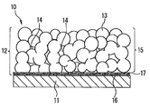
- FIG. 1 A schematic cross-sectional view of one embodiment of the electrode plate of the present invention is shown in FIG.
- An electrode plate 10 of the present invention shown in FIG. 1 includes a current collector 1 and an electrode active material layer 2.
- the electrode active material layer 2 is formed on the current collector 1 by a layer structure in which the active materials 3 are continuously present by at least partially joining the active materials 3 to each other. It consists of a porous void forming layer having voids 4 through which liquid can penetrate.
- FIG. 2 shows a schematic cross-sectional view of another embodiment of the electrode plate of the present invention.
- the electrode active material layer has a dense layer 17 in which the active material 16 is laminated on the current collector in a dense state substantially free of voids, and the active material 13 is at least partially joined on the dense layer 17.
- the porous material is formed by a layer structure in which the active material 13 is continuously present, and includes a porous void forming layer 15 having voids 14 into which the electrolytic solution can permeate.
- the active material 13 and the active material 16 contain the same metal element. For example, both may contain the same lithium transition metal composite oxide, or the constituent metal elements are the same. And compounds having different composition ratios of arbitrary elements may be used.
- the electrode active material layer 2 or the active material 3 in the electrode plate 10 and the electrode active material layer 12 or the active material 13 in the electrode plate 20 contain silicon. Details of the silicon content will be described later.
- the current collector used in the present invention is not particularly limited as long as it is generally used as a current collector for a non-aqueous electrolyte secondary battery electrode plate.
- a foil made of a simple substance such as an aluminum foil, a nickel foil, or a copper foil or an alloy, or a highly conductive foil such as a carbon sheet, a carbon plate, and a carbon textile is preferably used.
- seat, a film, a board, etc. other than the member with the small film thickness generally understood as foil may be sufficient.
- the thickness of the current collector is not particularly limited as long as it is generally a thickness that can be used as a current collector of an electrode plate for a non-aqueous electrolyte secondary battery, but is preferably 10 to 100 ⁇ m, and preferably 15 to 50 ⁇ m. Is more preferable.
- the method described above is used when the current collector surface is porous, has a large number of irregularities, or has a three-dimensional structure. It is also possible to apply manually.
- the current collector used in the present invention is preferable because corona treatment, oxygen plasma treatment, and the like can be performed in advance as necessary to further improve the film forming property of the electrode active material layer.
- the active material is continuously present by at least partially joining the chargeable / dischargeable active materials generally used in the electrode plate for a non-aqueous electrolyte secondary battery. And a porous void forming layer having voids through which the electrolytic solution can permeate.
- the electrode active material layer contains silicon.
- the active material includes a lithium transition metal composite oxide capable of lithium ion insertion / release reaction.
- the lithium transition metal composite oxide is a metal oxide containing lithium and a transition metal, and includes a metal oxide capable of exhibiting a lithium insertion / release reaction.
- the metal oxide in the present invention includes phosphorus oxide. That is, the lithium transition metal composite oxide includes a lithium transition metal composite phosphate compound.
- the metal oxide include a composite oxide of any one or more metals and lithium selected from transition metals such as cobalt, nickel, manganese, iron, and titanium, or a composition ratio thereof. Some of them may be changed, or some of the metals in these compounds may be replaced with different metals.
- lithium transition metal oxides such as lithium titanate such as Li 4 TI 5 O 12 and LiTiO 2 , lithium nickelate, lithium manganate, lithium cobaltate, and lithium iron phosphate;
- Examples include a compound in which the composition ratio of the oxide is changed, or a compound in which a part of the transition metal contained in the lithium transition metal oxide is replaced with another metal.
- the above does not limit the active material in this invention at all. It is preferable to select a lithium transition metal composite oxide as an active material in the present invention because an electrode plate suitable for a lithium ion secondary battery can be provided.
- Silicon in the electrode plate of the first invention is contained in the active material together with the lithium transition metal composite oxide.
- Silicon in the electrode plate of the first aspect of the present invention may be a silicon element, or may be a compound containing silicon such as silicon oxide, or a combination thereof.
- an active material containing a lithium transition metal composite oxide is generated on the current collector through the heating step in the manufacturing method. Since the heating temperature in the heating step is equal to or higher than the thermal decomposition temperature of the silicon element-containing compound contained in the electrode active material layer forming liquid, it is understood that the silicon-containing compound is not contained in the formed active material.
- a silane coupling agent can be used as a silicon-containing compound for imparting silicon contained in the active material. However, the silane coupling agent does not correspond to the compound containing silicon contained in the active material in the present invention.
- the lithium transition metal composite oxide contained in the active material exhibits a lithium insertion / extraction reaction
- the electrode plate of the present invention being capable of exerting a charge / discharge action. It can be confirmed simply by confirming that it exists.
- the lithium transition metal composite in which the metal oxide constituting the electrode active material layer can undergo lithium insertion / release reaction by analyzing the crystal structure or composition analysis of the lithium transition metal composite oxide contained in the active material. It can also be confirmed that it is an oxide. By confirming that the lithium transition metal composite oxide is capable of lithium insertion / release reaction, it can be confirmed that the active material action is exhibited.
- the electrode active material layer or the active material constituting the electrode active material layer is observed by mapping silicon using a TEM-EDX (Energy Dispersive X-ray Spectroscopy) technique. And it can be checked whether an active material contains silicon. At this time, although depending on the amount of silicon contained in the active material and the state of silicon, in many embodiments of the present invention, it is observed that silicon exists in the entire active material by the above mapping.
- the present inventors are configured by at least partially joining the active materials to each other.
- the porous void forming layer is included in the electrode active material layer, it has been found that when the active material contains silicon, an excellent effect is exhibited.
- the active material contains silicon, or silicon exemplified by silicon oxide, silicon nitride, silicon phosphate compound, silicon sulfide, silicon carbide, silicon fluoride, etc.
- silicon oxide silicon oxide
- silicon nitride silicon phosphate compound
- silicon sulfide silicon carbide
- silicon fluoride silicon fluoride
- examples of the compound containing silicon are not limited thereto.
- the production method of the electrode plate of the first invention is not particularly limited, but production by the production method of the invention described later is exemplified as a preferred embodiment.
- the electrode plate according to the second aspect of the present invention includes a current collector and an electrode active material layer formed on the current collector, as described above, and the electrode active material layer includes a part of the active materials. It includes a porous void forming layer that has a layer structure in which the active material is continuously present and has voids through which the electrolytic solution can permeate.
- the electrode active material layer contains a lithium transition metal composite oxide, and a Si—O bond of 1000 cm ⁇ 1 or more and 1100 cm ⁇ is obtained when an infrared absorption spectrum of the electrode active material layer is measured. When the half width of the peak appearing at 1 or less is 30 cm ⁇ 1 or more and 90 cm ⁇ 1 or less, the desired problem of the electrode plate of the present invention can be solved.
- any electrode active material layer may be used as long as the predetermined half-width can be confirmed when the infrared absorption spectrum of the electrode active material layer is measured.
- What is a specific material having a Si—O bond exhibiting a predetermined half width at half maximum, and what is a starting material for generating a Si—O bond that ultimately generates the Si—O bond is particularly limited Not.
- the manufacturing method of the electrode plate of 2nd this invention is not specifically limited, Manufacture by the manufacturing method of this invention mentioned later is illustrated as a preferable aspect.
- the compound containing silicon which is a factor indicating the half width at half maximum of the Si—O bond peak represented by the infrared absorption spectrum, is subjected to the heating step as described above. It is a compound containing silicon that can remain, and does not include, for example, a silane coupling agent in which the half-width of the peak is generally less than 30 cm ⁇ 1 .
- the measurement of the half width at half maximum of the electrode active material layer in the electrode plate of the present invention is carried out using the electrode plate of the present invention as a test piece and 1000 cm ⁇ of Si—O bonds obtained by measuring the infrared absorption spectrum of the surface of the electrode active material layer. It can be carried out by obtaining the half width at half maximum of the peak appearing at 1 or more and 1100 cm ⁇ 1 or less.
- the reason for the excellent effects of high output charge / discharge and bending characteristics in the electrode plate of the second invention is not clear, but the present inventors are configured by at least partially joining the active materials.
- the measurement of the infrared spectrum of the electrode active material layer shows a Si—O bond having a predetermined half-width at half maximum. Has been found to be demonstrated.
- the Si—O bond contained in the electrode active material layer is, for example, a compound containing silicon such as silicon oxide, silicon oxide carbide, silicon oxynitride, silicon oxyfluoride, etc. This may be attributed to being included in the layer, but is not limited thereto, and the silicon present in the electrode active material layer is bonded to any oxygen in the electrode active material layer including the current collector surface. If it is.
- the electrode plate for a non-aqueous electrolyte secondary battery of the present invention can be used as either a positive electrode plate or a negative electrode plate of a non-aqueous electrolyte secondary battery, or both of the positive electrode plate and the negative electrode plate of the present invention.
- An electrode plate may be used.
- the use of the electrode plate of the present invention as a positive electrode plate has a wide application range in that many metal oxides can be applied as a lithium transition metal composite oxide capable of lithium insertion / release reaction, and further combined with a conventional negative electrode. It is preferable because it can be used satisfactorily.
- the use of the electrode plate of the present invention as a negative electrode plate can improve the cycle characteristics of the negative electrode plate satisfactorily because the electrode plate of the present invention has excellent adhesion of the electrode active material layer to the current collector. Therefore, it is preferable.
- the electrode plate of the present invention is used for both positive and negative electrodes, the output charge / discharge performance of the non-aqueous electrolyte secondary battery can be improved more reliably, and various batteries can be used because of the excellent bending characteristics of the electrode plate. Forms can be implemented.
- the electrode active material layer in the present invention described above can form a coating film by bonding the active materials to each other and adhering to the current collector without using a binder. Therefore, the electrode plate of the present invention can be formed very thin compared to the thickness of the conventional electrode active material layer. In addition, the electrode plate of the present invention can shorten the moving distance of ions and electrons as compared with a conventional electrode active material layer using a resin binder. The above features are considered to be advantageous for high power charge / discharge.
- the electrode active material layer in the present invention can be formed to a thickness of 300 nm or more and 10 ⁇ m or less.
- the weight per unit thickness of the active material contained in the electrode active material layer relative to the conventional electrode active material layer in which the active materials adhere to each other solely depending on the binding action of the resinous binder It is possible to maintain a good electric capacity even by thinning.
- the electrode active material layer in the present invention can be formed with a thickness exceeding 10 ⁇ m. When it is desired to increase the capacity of the electrode plate, it can be designed to increase the thickness of the electrode active material layer as appropriate.
- the electrode plate of the present invention does not exclude the presence of a resin binder in the electrode active material layer.
- the electrode active material layer in the present invention may contain a resin binder. A method of incorporating a resin binder into the electrode active material layer will be described later.
- the size of the particles is not particularly limited, but a general active material constituting the conventional electrode active material layer It has the characteristic that it can be made smaller than the particle size of the particles.
- the surface area per unit weight of the electrode active material layer can be increased as compared with the conventional case. Since the surface area is understood as a contact area between the active material and the electrolytic solution, increasing the surface area means that an increase in the output of the electrode plate is promoted.
- the size of the active material constituting the electrode active material layer is preferably 200 nm or more and less than 900 nm with respect to the average maximum particle size.
- the particle size of the active material constituting the electrode active material layer is determined using an electron micrograph taken during electron microscope observation. That is, the particle size of the active material particles constituting the electrode active material layer is obtained from the electron micrograph obtained by the electron microscope observation using image analysis type particle size distribution measurement software (manufactured by Mountec Co., Ltd., MAC VIEW). Can do. About the average particle diameter of active material particle
- the lithium transition metal composite oxide generated on the current collector surface can be formed as very small particles.
- the small particle size of the active material which comprises an electrode active material layer as mentioned above the surface area per 1 weight unit of the said electrode active material layer can be increased compared with the past. As a result, even if the film thickness is thin, an excellent effect that a desirable electric capacity can be secured can be exhibited.
- the said surface area is understood as a contact area of an active material and electrolyte solution, it is preferable to increase the surface area of an active material since it means that the high output of an electrode plate is accelerated
- the particle size of the active material in the present invention exceeds the average minimum particle size and the range of the average maximum particle size.
- the particle size of the active material of the present invention may be determined as appropriate.
- the active material constituting the electrode active material layer in the present invention may not be in the form of particles, but may be in any non-particulate shape such as a pleated shape, a flake shape, or a flat shape. That is, the active material of the present invention is formed by a layer structure in which the active materials are continuously present by at least partially joining the active materials, and has a void through which the electrolytic solution can permeate. There is no particular limitation as long as a porous void forming layer can be formed. Moreover, since the active material which comprises the dense layer mentioned later is so small that recognition of a shape is impossible, it does not receive a restriction
- the electrode active material layer can be composed of only the active material described above, but may contain further additives within a range not departing from the gist of the present invention. For example, good conductivity can be secured without using a conductive material in the present invention, but this does not exclude the use of a conductive material in the present invention.
- the electrode active material layer in the present invention may appropriately contain a conductive material. Even when a conductive material is added, the thickness of the electrode active material layer can be 10 ⁇ m or less. Further, by adding the conductive material and increasing the amount of the active material, the thickness of the electrode active material layer can be formed to a thickness exceeding 10 ⁇ m, and the capacity of the electrode plate can be increased.
- the fixing aspect in which the active material and the conductive material are in direct contact and / or the lithium transition metal composite oxide in which the conductive materials are included in the active material The aspect which adheres through is included.
- the electrode active material layer in the present invention includes an embodiment in which the conductive material and the active material or the conductive materials are fixed without using a non-conductive binder such as a resin binder, so that an excellent conductive path can be obtained. Can be formed. It is presumed that the conductive path effectively acts on the high output charge / discharge of the electrode plate.
- the conductive material those usually used for electrode plates for non-aqueous electrolyte secondary batteries can be used, and examples thereof include carbon materials such as carbon black such as acetylene black and ketjen black.
- the average primary particle size of the conductive material is preferably about 20 nm to 50 nm. The average primary particle size is obtained by an arithmetic average obtained from actual measurement using an electron microscope, as in the method of measuring the particle size of the active material. When using a conductive material, it is necessary to keep in mind that the gap in the electrode active material layer 3 is maintained to such an extent that the electrolytic solution can permeate.
- the electrode active material layer 3 may contain a metal oxide that does not function as an active material in order to further improve the adhesion between the current collector and the active material.
- the metal oxide as the additive is not particularly limited, and examples thereof include cobalt oxide, nickel oxide, titanium oxide, zirconium oxide, tin oxide, and manganese oxide.
- the electrode active material layer in the electrode plate of the present invention is formed by a layer structure in which the active materials are continuously present in the current collector by partially joining the active materials, and the electrolyte solution is It includes a porous void forming layer having permeable voids.
- the electrode active material layer in the present invention as in the electrode plate 10 shown in FIG. 1, the gap may exist up to the vicinity of the current collector, or a part of the gap may face the current collector. That is, the electrode active material layer may be substantially composed of only the porous void forming layer.
- the electrode active material layer in the present invention may be configured such that a dense layer is provided on a current collector and a void forming layer is further provided on the dense layer, as in the electrode plate 20 shown in FIG. Good.
- the dense layer is formed by a layer structure in which the active materials are continuously present when the active materials are bonded to each other, and is substantially free of voids.
- the void-forming layer is a porous void-forming layer having a structure in which the active materials are partially joined to each other and the active material is continuously present, and has voids through which the electrolytic solution can permeate.
- the dense layer and the void forming layer are formed from components having the same contents. That is, the active material constituting the dense layer and the active material constituting the void forming layer are active materials having the same composition.
- the composition ratio of both is not only completely the same, but in a range not departing from the gist of the present invention. May be different.
- either one or both of the metal oxide that is the active material constituting the dense layer and the metal oxide that is the active material constituting the void forming layer can be understood to have the same composition.
- the crystal structure of the compound can be confirmed as a method for judging that the active material constituting the dense layer and the active material constituting the void forming layer are the same compound by another means other than analysis of the chemical composition. May be. That is, when the dense layer and the void-forming layer are observed with a transmission electron microscope and the crystal structure of the metal oxide as the active material in the two layers is the same, it can be determined that both are the same compound.
- the same crystal structure means that the crystal structure is included in the same crystal phase. In other words, when the active material particles and the metal oxide are not the same, it means that the crystal structures of the two are located in different crystal phases, and the narrowly defined identity based on the difference in the objectivity of the crystal lattice. Not intended.
- the state in which there is substantially no void with respect to the dense layer is a state in which no gap is observed with the naked eye when the active materials are closely bonded to each other and observed with a scanning electron microscope at a magnification of 50,000 times. It shall be shown.
- the void in which the electrolyte solution can permeate in the void-forming layer is a void formed around the active material by partial and direct bonding, and is 50,000 times magnification in an electron microscope. When observed, the gap should be such that it can be observed with the naked eye. There is a tendency that the particle size of the active material constituting the dense layer is smaller than that of the active material constituting the void forming layer.
- the thickness of the dense layer in the formed electrode active material layer tends to be significantly thinner than the thickness of the void forming layer.
- the dense layer is present between the gap forming layer and the current collector, so that the non-aqueous electrolyte secondary battery using the electrode plate is charged and discharged. Since the exchange of electrons between the current collector and the void forming layer becomes very smooth, an improvement in conductivity is expected.
- the manufacturing method of the electrode plate of the aspect which does not have a dense layer, and the electrode plate of the aspect which has a dense layer is mentioned later.
- the electrode plate of the present invention is excellent in output charge / discharge performance.
- the output charge / discharge performance can be confirmed by measuring the DC resistance value of the electrode plate. That is, when the DC resistance value is smaller, it can be evaluated that the output charge / discharge performance of the electrode plate is high.
- the output charge / discharge performance of the electrode plate of the present invention can be evaluated by determining the discharge capacity maintenance rate (%). That is, a predetermined discharge rate is set, and a charge / discharge test is performed based on the theoretical value of the discharge capacity (mAh / g) of the active material. And it can carry out by calculating
- a discharge capacity maintenance rate of 50% or more is shown at a discharge rate of 50C or more. More preferably, it is desirable that a discharge capacity maintenance rate of 50% or more is exhibited at a discharge rate of 100C or more. However, if the discharge rate is 2000 C or higher, a system that can withstand a large current is required, which is not desirable.
- the discharge capacity maintenance rate is high.
- the discharge capacity maintenance rate is 50% or more, or 80% or more, and even 100%. It is desirable that the rate be indicated.
- the electrode plate of the present invention is excellent in bending strength.
- the bending strength of the electrode plate of the present invention can be measured by the following bending test. In order to confirm whether or not the bending strength is improved in the electrode plate of the present invention, a reference electrode plate prepared in the same manner as the present invention was prepared except that silicon was not contained. The bending strength of the electrode plate may be subjected to the following bending test and the results compared.
- a reference solution prepared in the same manner as the electrode active material layer forming solution in this production method is prepared except that no silicon-containing compound such as a silane coupling agent is added.
- a coating film is formed on the surface of the current collector through the same steps as in this production method, and a heating step is performed.
- a reference electrode plate in which a reference electrode active material layer is formed on a current collector is prepared.
- a bending test is performed using a cylindrical mandrel tester. The bending test is conducted based on JIS K 5600-5-1.
- M1 mandrel diameter
- a test piece is prepared using the electrode plate of the present invention, and the diameter (M2) of the mandrel exhibiting peeling resistance is also specified for this test piece in the same manner as the reference electrode plate.
- the electrode plate of the present invention hardly peels off or cracks even if the diameter of the mandrel is small, that is, M1> M2. This also indicates that the electrode plate of the present invention has improved adhesion between the electrode active material layer and the current collector.
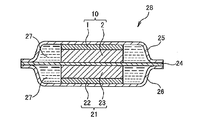
- the nonaqueous electrolyte secondary battery of the present invention generally includes a negative electrode plate 21 in which an electrode active material layer 23 is provided on one surface side of a current collector 22 and a negative electrode plate 21 as illustrated in FIG.
- a positive electrode plate 10 in which the electrode active material layer 2 is provided on one side of the current collector 1 to be combined, and a separator 24 such as a polyethylene porous film are provided therebetween. These are housed in the exteriors 25 and 26 and are sealed and manufactured in a state where the exteriors 25 and 26 are filled with the non-aqueous electrolyte 27 to form the non-aqueous electrolyte secondary battery 28.
- the nonaqueous electrolyte secondary battery 28 uses the positive electrode plate 10 of the present invention, and the negative electrode plate 21 may be the electrode plate of the present invention or any electrode plate.
- the nonaqueous electrolyte secondary battery of the present invention is characterized in that, in particular, the electrode plate for a nonaqueous electrolyte secondary battery of the present invention described above is used as at least one of the positive electrode plate and the negative electrode plate. Therefore, the effect brought about by the electrode plate of the present invention is also reflected in the nonaqueous electrolyte secondary battery. Therefore, since it is a non-aqueous electrolyte secondary battery that exhibits excellent output charge / discharge and exhibits the bending characteristics of the electrode plate, it is possible to provide various types of battery non-aqueous electrolyte secondary batteries.
- the negative electrode plate is composed of a carbonaceous material
- the porosity of the positive electrode plate is lowered, and the permeability of the electrolytic solution is lowered, so that it is difficult to increase the output of the battery.
- the electrode plate of the present invention is an electrode plate having excellent input / output characteristics, when it is used as a positive electrode plate, it is possible to reduce the amount of conductive material used as compared with the prior art.
- non-aqueous electrolyte secondary batteries do not insert and remove lithium ions such as metallic lithium and its alloys, tin, silicon, and their alloys as a negative electrode active material used for the negative electrode plate, rather than carbonaceous materials such as graphite.
- the aspect which comprises a negative electrode plate using the material which can be separated is also included.
- a nonaqueous electrolyte secondary battery can be produced by positively using the electrode plate of the present invention as a negative electrode.
- a non-aqueous electrolyte secondary battery can be configured by using the electrode plate of the present invention for both the positive electrode plate and the negative electrode plate.
- the electrode plate of the present invention when used in either the positive electrode or the negative electrode, the other electrode plate is used in the non-aqueous electrolyte secondary battery.
- a conventionally known electrode plate can be used as appropriate.
- active material particles made of a lithium transition metal composite oxide, a conductive material, a resin binder are generally formed on the same collector surface as the current collector used in the electrode plate of the present invention.
- a coating film is formed by applying a composition in which a dressing material or the like is dispersed, and the coating film is heated and dried, and pressed as necessary, but is not limited thereto. You may use the electrode plate manufactured by the other structure or the other manufacturing method.
- a copper foil such as an electrolytic copper foil or a rolled copper foil having a thickness of about 5 to 50 ⁇ m is used as a current collector, and an electrode active in the negative electrode plate is formed on at least a part of the current collector surface.
- coating a material layer forming composition, drying, and pressing as needed is used, it is not limited to this. You may use the negative electrode plate manufactured by the other structure or the other manufacturing method.
- the electrode active material layer forming composition in the negative electrode plate generally includes an active material composed of a carbonaceous material such as natural graphite, artificial graphite, amorphous carbon, carbon black, or a material obtained by adding a different element to these components.
- additives are dispersed and mixed.
- Nonaqueous electrolyte used in the present invention is not particularly limited as long as it is generally used as a non-aqueous electrolyte for a non-aqueous electrolyte secondary battery, but a lithium salt is dissolved in an organic solvent.
- a non-aqueous electrolyte is preferably used.
- lithium salts examples include inorganic lithium salts such as LiClO 4 , LiBF 4 , LiPF 6 , LiAsF 6 , LiCl, and LiBr; LiB (C 6 H 5 ) 4 , LiN (SO 2 CF 3 ) 2 , LiC ( Organics such as SO 2 CF 3 ) 3 , LiOSO 2 CF 3 , LiOSO 2 C 2 F 5 , LiOSO 2 C 4 F 9 , LiOSO 2 C 5 F 11 , LiOSO 2 C 6 F 13 , and LiOSO 2 C 7 F 15 Typical examples include lithium salts.
- inorganic lithium salts such as LiClO 4 , LiBF 4 , LiPF 6 , LiAsF 6 , LiCl, and LiBr
- LiB (C 6 H 5 ) 4 LiN (SO 2 CF 3 ) 2
- LiC Organics such as SO 2 CF 3 ) 3 , LiOSO 2 CF 3 , LiOSO 2 C 2 F 5
- Examples of the organic solvent used for dissolving the lithium salt include cyclic esters, chain esters, cyclic ethers, and chain ethers.
- cyclic esters examples include propylene carbonate, butylene carbonate, ⁇ -butyrolactone, vinylene carbonate, 2-methyl- ⁇ -butyrolactone, acetyl- ⁇ -butyrolactone, and ⁇ -valerolactone.
- chain esters examples include dimethyl carbonate, diethyl carbonate, dibutyl carbonate, dipropyl carbonate, methyl ethyl carbonate, methyl butyl carbonate, methyl propyl carbonate, ethyl butyl carbonate, ethyl propyl carbonate, butyl propyl carbonate, propionic acid alkyl ester, Examples include malonic acid dialkyl esters and acetic acid alkyl esters.
- cyclic ethers examples include tetrahydrofuran, alkyltetrahydrofuran, dialkyltetrahydrofuran, alkoxytetrahydrofuran, dialkoxytetrahydrofuran, 1,3-dioxolane, alkyl-1,3-dioxolane, and 1,4-dioxolane.
- chain ethers examples include 1,2-dimethoxyethane, 1,2-diethoxyethane, diethyl ether, ethylene glycol dialkyl ether, diethylene glycol dialkyl ether, triethylene glycol dialkyl ether, and tetraethylene glycol dialkyl ether. It is done.
- the structure of the non-aqueous electrolyte secondary battery of the present invention manufactured using the positive electrode plate, the negative electrode plate, the separator, and the non-aqueous electrolyte can be selected from conventionally known structures as appropriate.
- a structure in which a positive electrode plate and a negative electrode plate are wound in a spiral shape through a separator such as a polyethylene porous film and stored in a battery container can be mentioned.
- a structure in which a positive electrode plate and a negative electrode plate cut into a predetermined shape are stacked and fixed via a separator, and this is housed in a battery container may be employed. It is not limited.
- the lead wire attached to the positive electrode plate is connected to the positive electrode terminal provided in the outer container, while being attached to the negative electrode plate.
- a non-aqueous electrolyte secondary battery can be manufactured by connecting the lead wire to a negative electrode terminal provided in the outer container, and further filling the battery container with a non-aqueous electrification solution and then sealing it.
- the nonaqueous electrolyte secondary battery using the electrode plate of the present invention as a positive electrode plate and / or a negative electrode plate can be used as a so-called nonaqueous electrolyte secondary battery used in a battery pack. That is, the battery pack of the present invention uses the electrode plate of the present invention as a positive electrode plate and / or a negative electrode plate, and includes a nonaqueous electrolyte secondary battery including a positive electrode terminal and a negative electrode terminal, and a protection circuit having an overdischarge protection function Are housed in a storage case.
- the battery pack of the present invention is equipped with a protection function for protecting the battery from, for example, overcharge, overdischarge, overcurrent, a short circuit of the battery peripheral circuit, a short circuit between the positive and negative electrodes, etc., in the nonaqueous electrolyte secondary battery itself.
- it may be a battery pack in which a protection circuit for preventing overcharge and overdischarge is housed and integrated in a storage case together with the non-aqueous electrolyte secondary battery.
- the battery pack of the present invention can be suitably used as a battery power supply device for a device that consumes a large amount of power relative to the scale of the device, such as a portable device such as a notebook computer, a camera, or a mobile phone.
- FIG. 4 shows a schematic exploded view of a battery pack 30 of the present invention using a lithium ion secondary battery 31 configured by using the electrode plate of the present invention as a positive electrode plate as one embodiment of the battery pack of the present invention.
- the battery pack 30 includes a lithium ion secondary battery 31 housed in a resin container 36a, a resin container 36b, and an end case 37.
- a substrate 34 is provided.
- the protection circuit board 34 includes an external connection connector 35.
- the external connection connector 35 is inserted into an external connection window 38a provided in the resin container 36a and an external connection window 38b provided in the end case 37. Connected to an external terminal.
- the protection circuit board 34 includes a charge / discharge safety circuit (not shown) for controlling charge / discharge, a wiring circuit for connecting the external connection terminal and the lithium ion secondary battery 31, and the like.
- the battery pack 30 can employ
- the battery pack 30 includes a positive electrode lead plate connected to the positive electrode terminal 32, a negative electrode lead plate connected to the negative electrode terminal 33, an insulator, and the like between the lithium ion secondary battery 31 and the end case 37. , May be provided as appropriate.
- the non-aqueous electrolyte secondary battery of the present invention using the electrode plate of the present invention has functions such as overcurrent blocking and battery temperature monitoring in addition to the above-described protection circuit, in addition to the usage mode for battery packs.
- the protection circuit may be used by being integrated with the secondary battery itself.
- the battery pack can be used as a secondary battery having a protection function and a protection circuit without constituting a battery pack, and is highly versatile.
- some aspects mentioned above are only illustrations, and do not limit use of the electrode plate of this invention, or the nonaqueous electrolyte secondary battery of this invention at all.
- the electrode plate for a non-aqueous electrolyte secondary battery includes a current collector and an electrode active material layer made of an active material, and the electrode active material layer is formed on the current collector.
- the production method of the present invention can produce the electrode plate of the first invention described above and the electrode plate of the second invention described above.
- the electrode plate of the first invention one or more of the lithium element-containing compounds and one or more of the transition metal element-containing compounds are dissolved in at least a solvent, and one or more of the silicon-containing compounds are dissolved.
- An electrode active material layer forming liquid containing two or more types is prepared, the electrode active material layer forming liquid is applied to a current collector to form a coating film, and the current collector on which the coating film is formed is used as the lithium Lithium transition metal composite oxide capable of lithium insertion and desorption reaction on the current collector, and silicon by heating above the thermal decomposition temperature of the element-containing compound, the transition metal element-containing compound, and the silicon element-containing compound It can manufacture by producing
- one or more of the lithium element-containing compounds and one or more of the transition metal element-containing compounds are dissolved in at least a solvent.
- An electrode active material layer forming liquid containing one or more kinds is prepared, and the electrode active material layer forming liquid is applied to a current collector to form a coating film.
- an active material containing, and, above comprises an active material, the peaks appearing 1000 cm -1 or 1100 cm -1 in the following Si-O bond obtained when measuring the infrared absorption spectrum half width at half maximum, 30 cm -1
- Can be prepared by forming an electrode active material layer is above 90cm -1 or less.
- the electrode active material formed by the production method of the present invention is used. In the measurement of the infrared absorption spectrum of the material layer, manufacturing conditions may be adjusted by grasping in a preliminary experiment whether or not a predetermined half-width is shown.
- a lithium element-containing compound and a transition metal element-containing compound which are precursors of an active material
- a silicon element-containing compound is added, and an additive is added as necessary.
- An active material layer forming solution is prepared.
- the silicon element-containing compound may be dissolved in the solvent, or may be mixed, dispersed, or the like without being dissolved.
- it is preferable that the silicon element-containing compound is also dissolved in the solvent.
- the resin binder is not substantially added to the electrode active material forming liquid, and when the active material is generated on the surface of the current collector, the active materials are partially directly with each other. A part of the active material produced while bonding is in close contact with the current collector surface, and the coating film is fixed to the current collector surface as a whole.
- the electrode active material layer or the active material contained in the electrode active material layer contains silicon or a compound containing silicon.
- the electrode active material layer-forming liquid contains a lithium element-containing compound and a transition metal element-containing compound containing a metal element constituting a lithium transition metal composite compound capable of lithium insertion / release reaction formed on a current collector. It can be prepared by using them as precursors of substances, dissolving them in a solvent, and adding necessary additives.
- the lithium element-containing compound and the transition metal element-containing compound may be collectively referred to as a metal element-containing compound.
- the lithium transition metal composite oxide is included in the active material of the present invention. That is, the lithium transition metal composite oxide may be the active material itself, or the active material may be configured to include the lithium transition metal composite oxide and any element or compound.
- the lithium transition metal composite oxide includes a lithium transition metal composite phosphate compound.
- the transition containing the 1 type (s) or 2 or more types of a lithium element containing compound, and at least 1 sort (s) of transition metal selected from the group which consists of transition metals, such as cobalt, nickel, manganese, iron, or titanium One or more metal element-containing compounds are used.
- the metal element-containing compound is selected according to the lithium transition metal composite oxide that is scheduled to be generated as a compound capable of lithium insertion / release reaction.
- the metal element-containing compound examples include salts having a lithium element as a metal element, and salts having a metal other than lithium, such as cobalt, as a metal element.
- These salts include metal element chlorides, nitrates, sulfates, perchlorates, acetates, phosphates, bromates, and the like.
- chloride, nitrate, and acetate are preferably used because they are easily available as general-purpose products.
- nitrate is preferably used because it has good film forming properties for a wide variety of current collectors.
- LiCoO 2 when LiCoO 2 is finally produced as a lithium transition metal composite oxide constituting the active material produced on the current collector, Li is used as an active material precursor for producing LiCoO 2.
- a compound containing a metal element and a compound containing Co as a metal element can be used in combination as a main raw material.
- LiNiO 2 is finally produced as a lithium transition metal composite oxide on the current collector, as an active material precursor for producing LiNiO 2 , a compound containing Li as a metal element, and Ni as a metal element A compound containing an element can be used in combination as a main raw material.
- LiMn 2 O 4 is finally produced as a lithium transition metal composite oxide on the current collector, as an active material precursor for producing LiMn 2 O 4 , a compound containing Li as a metal element, And a compound containing Mn as a metal element can be used in combination as a main raw material.
- LiFeO 2 is finally produced as a lithium transition metal composite oxide on the current collector, as an active material precursor for producing LiFeO 2 , a compound containing Li as a metal element, and Fe as a metal A compound containing an element can be used in combination as a main raw material.
- LiTiO 2 is finally produced as a lithium transition metal composite oxide on the current collector, as an active material precursor for producing LiTiO 2 , a compound containing Li as a metal element, and Ti as a metal A compound containing an element can be used in combination as a main raw material.
- examples of the compound containing Li as a metal element include lithium citrate tetrahydrate, lithium perchlorate trihydrate, lithium acetate dihydrate, Examples thereof include lithium nitrate and lithium phosphate.
- the lithium transition metal complex oxide in this invention is not limited.
- the chemical formula exemplified above may be one in which the composition ratio of the constituent elements is changed, or one in which some constituent elements are replaced with other arbitrary elements.
- Examples of the compound containing Co as a metal element include cobalt chloride (II) hexahydrate, cobalt (II) formate dihydrate, cobalt (III) acetylacetonate, and cobalt (II) acetylacetonate dihydrate. , Cobalt (II) acetate tetrahydrate, cobalt (II) oxalate dihydrate, cobalt (II) nitrate hexahydrate, cobalt (II) ammonium hexahydrate, cobalt (III) nitrite Examples thereof include sodium and cobalt (II) sulfate heptahydrate.
- Examples of the compound containing Ni as a metal element include nickel (II) chloride hexahydrate, nickel acetate (II) tetrahydrate, nickel (II) perchlorate hexahydrate, and nickel (II) bromide. Trihydrate, nickel (II) nitrate hexahydrate, nickel (II) acetylacetonate dihydrate, nickel (II) hypophosphite hexahydrate, and nickel (II) sulfate hexahydrate Etc.
- Examples of the compound containing Mn as a metal element include manganese acetate (III) dihydrate, manganese nitrate (II) hexahydrate, manganese (II) sulfate pentahydrate, and manganese (II) oxalate dihydrate. Examples thereof include Japanese, and manganese (III) acetylacetonate.
- Examples of the compound containing Fe as a metal element include iron chloride (II) tetrahydrate, iron (III) citrate, iron (II) acetate, iron (II) oxalate dihydrate, iron nitrate (III ) Nonahydrate, iron (II) lactate trihydrate, and iron (II) sulfate heptahydrate.
- Examples of the compound containing Ti as a metal element include titanium tetrachloride and titanium acetylacetonate.
- a combination ratio of a compound containing Li as a metal element and a compound containing Co as a metal element used as a main raw material is not particularly limited, but is preferably 1 ⁇ X1 ⁇ 2, and more preferably 1 ⁇ X2 ⁇ 1.2.
- a combination ratio of a compound containing Li as a metal element and a compound containing Ni as a metal element used as a main raw material is not particularly limited, but preferably 1 ⁇ X2 ⁇ 2, more preferably 1 ⁇ X2 ⁇ 1.2.
- a combination ratio of a compound containing Li as a metal element as a main raw material and a compound containing Mn as a metal element is not particularly limited, but is preferably 0.5 ⁇ X3 ⁇ 1, and more preferably 0.5 ⁇ X3 ⁇ 0.6.
- a combination ratio of a compound containing Li as a metal element and a compound containing Fe as a metal element used as a main raw material is not particularly limited, but is preferably 1 ⁇ X4 ⁇ 2, and more preferably 1 ⁇ X4 ⁇ 1.2.
- a combination ratio of a compound containing Li as a metal element as a main raw material and a compound containing Ti as a metal element is not particularly limited, but is preferably 1 ⁇ X5 ⁇ 2, and more preferably 1 ⁇ X5 ⁇ 1.2.
- the electrode active material layer forming liquid may be used in combination with other raw materials as required.
- a compound serving as a specific element supply source may be further added to the electrode active material layer forming liquid according to the elemental composition of the substance constituting the lithium transition metal composite oxide.
- the electrode active material layer forming solution contains a phosphorus element as a material that serves as a phosphorus element supply source in addition to the metal element supply source compound.
- a compound may be blended.
- Phosphorous element-containing compounds can include phosphoric acid compounds, phosphorous acid compounds, etc.
- phosphoric acid compounds can include phosphoric acid and salts thereof
- phosphorous acid compounds include phosphorous acid. And salts thereof.
- Examples of the phosphorus element-containing compound include phosphoric acid, phosphorous acid, hypophosphorous acid, diisopropyl phosphite, ammonium phosphate, ammonium phosphite, and ammonium hypophosphite.
- the electrode active material layer forming liquid contains a compound containing Li as a metal element and a compound containing Fe as a metal element as a compound serving as a metal element supply source. It may be a solution prepared using a combination of compounds and further using a phosphorus element-containing compound.
- the total concentration of the lithium element and other metal elements in the solution containing the lithium element-containing compound and the selected metal element-containing compound is 0.01 to 5 mol / L, particularly 0.1 to 2 mol / L. preferable.
- concentration 0.01 mol / L or more
- the current collector and the active material generated on the surface of the current collector can be satisfactorily adhered, and the active material can be fixed.
- concentration by setting the concentration to 5 mol / L or less, it is possible to maintain a good viscosity enough to apply the electrode active material layer forming liquid to the current collector surface, and to form a uniform coating film. can do.
- the silicon-containing compound in the production method of the present invention is a predetermined silicon or silicon contained in the electrode active material layer or the active material contained in the electrode active material layer in the electrode plate produced by the production method of the present invention.
- Any compound can be used as long as it can impart a compound containing Specific examples include organic silicon-containing compounds such as silane coupling agents, silyl isocyanate, alkyl silicate, and siloxane, and inorganic silicon-containing compounds such as polysilane.
- organic silicon-containing compounds such as silane coupling agents, silyl isocyanate, alkyl silicate, and siloxane
- inorganic silicon-containing compounds such as polysilane.
- the heating temperature in the heating step of the production method of the present invention is equal to or higher than the thermal decomposition temperature of the silicon-containing compound, any silicon-containing compound may be subjected to thermal decomposition of silicon or a compound containing silicon.
- the active material layer or the active material layer it is not limited to the above examples, and various silicon-containing compounds can be used. From the viewpoint of good compatibility with the solvent, an organic silicon-containing compound is preferred.
- the organic silicon-containing compound means a compound containing silicon and carbon
- the inorganic silicon-containing compound means a compound containing silicon and not containing carbon.
- silicon-containing compounds having a hydrolyzable group are more preferable for the following reasons. That is, since the hydrolyzable group adheres well to the surface of the inorganic compound, it is expected that the hydrolyzable group adheres well to the surface of the generated lithium transition metal composite acid acid during the manufacturing process. .
- action which improves the adhesive force of 1 is anticipated (1st effect
- the lithium transition metal composite oxide is further formed by covering the silicon element bonded to the hydrolyzable group by adhesion to the lithium transition metal composite oxide by the hydrolyzable group. It is possible to satisfactorily realize the first aspect of the present invention including silicon in the active material (second action). Therefore, from the viewpoint of enjoying the first action and / or the second action described above, among the organic silicon-containing compounds, silicon having a hydrolyzable group such as a silane coupling agent, silyl isocyanate, and alkyl silicate. Containing compounds are preferred.
- the term “adhesion” used for the hydrolyzable group and the reactive functional group broadly describes the state in which the two are linked by the interaction between the hydrolyzable group and the lithium transition metal composite oxide. For example, it may be a chemical bond, but is not limited thereto.
- a silane coupling agent has a hydrolyzable group (such as an ethoxy group or a methoxy group) capable of generating a silanol group (Si—OH) and an alcohol by hydrolysis on one end side of the molecular structure.
- the reactive functional group was selected from the group consisting of vinyl group, epoxy group, styryl group, methacryloxy group, acryloxy group, amino group, ureido group, chloropropyl group, mercapto group, polysulfide group, and isocyanate group.
- the reactive functional group adheres well to a lithium element-containing compound, a transition metal element-containing compound, or an optionally added resin.
- the reactive functional group is likely to be combined with the raw material before thermal decomposition. Therefore, the silane coupling agent adheres to the raw material being thermally decomposed or the ultrafine particles of the generated lithium transition metal composite oxide by the hydrolyzable group at one end, while the reactivity at the other end It adheres to the raw material before thermal decomposition by the functional group.
- the silane coupling agent itself is thermally decomposed by heating in the heating process, adhesion between the lithium transition metal composite oxides finally formed is promoted by promoting adhesion between raw materials in the manufacturing process. Alternatively, it is speculated that it is possible to improve the adhesion between the active materials containing the lithium transition metal composite oxide.
- a silane coupling agent is preferably selected as at least one silicon-containing compound of one or more silicon-containing compounds in the production method of the present invention.
- those having a vinyl group as a reactive functional group are vinyl trichlorosilane, vinyltrimethoxysilane, vinyltriethoxysilane, allyltrichlorosilane, allyltriethoxysilane, allyltrimethoxysilane, diethoxymethyl.
- vinyl silane and trichlorovinyl silane examples include vinyl silane and trichlorovinyl silane.
- Examples of those having an epoxy group as a reactive functional group include 2- (3,4-epoxycyclohexyl) ethyltrimethoxysilane, 3-glycidoxypropyltrimethoxysilane, 3-glycidoxypropylmethyldiethoxysilane, 3 -Glycidoxypropyltriethoxysilane and the like.
- Examples of those having a styryl group as a reactive functional group include p-styryltrimethoxysilane.
- Examples of those having a methacryloxy group as a reactive functional group include 3-methacryloxypropylmethyldimethoxysilane, 3-methacryloxypropyltrimethoxysilane, 3-methacryloxypropylmethyldiethoxysilane, 3-methacryloxypropyltriethoxysilane, etc. Can be mentioned. Examples of those having an acryloxy group as a reactive functional group include 3-acryloxypropyltrimethoxysilane.
- Examples of those having an amino group as a reactive functional group include N-2- (aminoethyl) -3-aminopropylmethyldimethoxysilane, N-2- (aminoethyl) -3-aminopropyltrimethoxysilane, N-2 -(Aminoethyl) -3-aminopropyltriethoxysilane, 3-aminopropyltrimethoxysilane, 3-aminopropyltriethoxysilane, 3-triethoxysilyl-N- (1,3-dimethyl-butylidene) propylamine, Examples thereof include N-phenyl-3-aminopropyltrimethoxysilane and N- (vinylbenzyl) -2-aminoethyl-3-aminopropyltrimethoxysilane.
- Examples of those having a ureido group as a reactive functional group include 3-ureidopropyltriethoxysilane.
- Examples of those having a chloropropyl group as a reactive functional group include 3-chloropropyltrimethoxysilane.
- Examples of those having a mercapto group as a reactive functional group include 3-mercaptopropylmethyldimethoxysilane and 3-mercaptopropyltrimethoxysilane.
- Examples of those having a polysulfide group as a reactive functional group include bis (triethoxysilylpropyl) tetrasulfide.
- Examples of those having an isocyanate group as a reactive functional group include 3-isocyanatopropyltriethoxysilane.
- the silane coupling agent preferably has a vinyl group, a methacryloxy group, or an amino group as a reactive functional group from the viewpoint of improving the adhesion between the current collector and the electrode active material layer.
- a silane coupling agent it is preferable to add in the range of 1 weight% or more and 25 weight% or less with respect to the electrode active material layer formation liquid whole quantity.
- the amount of the silane coupling agent within this range, the electrode active material layer and the current collector can be formed while suppressing the possibility that inhibition of the generation of the active material is suppressed when the coating film is heated.
- the effect that the adhesiveness can be enhanced can be further enhanced.
- silyl isocyanate examples include, but are not limited to, methyl triisocyanate silane and tetraisocyanate silane.
- alkyl silicate examples include, but are not limited to, tetramethoxysilane, polymethoxysiloxane, and tetra-n-propoxysilane.
- the addition amount of the silicon-containing compound is preferably in the range of 1% by weight to 25% by weight with respect to the total amount of the electrode active material layer forming liquid. Adhesion between the electrode active material layer to be formed and the current collector while suppressing the possibility that the inhibition of the generation of the active material is suppressed when the coating film is heated because the addition amount of the silicon-containing compound is within this range. The effect that the property can be enhanced can be further enhanced.
- the electrode active material layer forming liquid may contain further additives.
- the electrode active material layer in the electrode plate manufactured by this manufacturing method, the electrode active material layer can ensure good conductivity without requiring the use of a conductive material, which includes a conductive material in the electrode active material layer. It is not intended to exclude that. For this reason, a conductive material may be added to the electrode active material layer forming liquid to form an electrode active material layer containing the conductive material. Even when a conductive material is added, the thickness of the electrode active material layer can be reduced to a level of 10 ⁇ m or less.
- the thickness of the electrode active material layer finally formed may be more than 10 ⁇ m. More specifically, when the conductive material is added to the electrode active material layer forming liquid, the added amount of the conductive material is 5 to 20 parts by weight with respect to 100 parts by weight of the active material generated on the current collector surface. It is desirable to use parts by weight.
- the above description is not intended to exclude the addition of the conductive material in excess of 20 weight, but the electrode active material layer in the present invention has a good conductivity due to the presence of the dense layer, and therefore 20 weight. It is the meaning that sufficiently excellent conductivity can be exhibited by the use of a conductive material of a part or less.
- the conductive material those usually used for electrode plates for non-aqueous electrolyte secondary batteries can be used, and examples thereof include carbon materials such as carbon black such as acetylene black and ketjen black.
- the average particle diameter of the conductive material is preferably about 20 nm to 50 nm. The average particle diameter is obtained by an arithmetic average obtained from actual measurement using an electron microscope, as in the method of measuring the particle diameter of the active material.
- a metal oxide that does not function as an active material may be included in the electrode active material layer.
- the metal oxide as the additive is not particularly limited, and examples thereof include cobalt oxide, nickel oxide, titanium oxide, zirconium oxide, tin oxide, and manganese oxide.
- the solvent used for dissolving the lithium element-containing compound and the transition metal element-containing compound is not particularly limited as long as it can dissolve the lithium element-containing compound and the selected metal element-containing compound.
- lower alcohols having a total carbon number of 5 or less such as methanol, ethanol, isopropyl alcohol, propanol, butanol, diketones such as acetylacetone, diacetyl, benzoylacetone, ethyl acetoacetate, ethyl pyruvate, ethyl benzoylacetate, ethyl benzoylformate And ketoesters such as toluene, a mixed solvent thereof and the like, or a mixed solvent of these various solvents and water.
- the solvent used in the present invention can further dissolve the silicon-containing compound.
- a silicon-containing compound that can be dissolved in a solvent used to dissolve the lithium element-containing compound and the transition metal element-containing compound may be selected
- the electrode active material layer forming liquid prepared as described above is applied on at least a part of the current collector surface by a conventionally known coating method, for example, printing, spin coating, dip coating, bar coating, spray coating or the like. Applied. At this time, a coating film is formed on the surface of the current collector.
- the current collector to which the electrode active material layer forming liquid is applied is generally used as a current collector for a positive electrode plate or a current collector for a negative electrode plate, which serves as an electrode plate for a non-aqueous electrolyte secondary battery. If it can be used, it can employ
- the amount of the electrode active material layer-forming liquid applied to the current collector can be arbitrarily determined according to the application of the electrode plate to be produced, etc., but the electrode active material layer in the present invention is very Since it can be formed thin, when it is desired to reduce the film thickness, the electrode active material layer after heating may be thinly applied so as to have a thickness of about 300 nm to 10 ⁇ m.
- a coating film for forming an electrode active material layer containing a metal element compound that is a precursor of an active material by applying an electrode layer forming solution on at least a part of the surface of the current collector Simply referred to as “coating film”).
- heating step Next, the current collector on which the coating film is formed is heated (heating step).
- the heating temperature in the heating step is determined at a temperature equal to or higher than the thermal decomposition temperature of the lithium element-containing compound, the transition metal element-containing compound, and the silicon element-containing compound. In many aspects of the invention, the heating temperature is 150 ° C. or higher.
- the heating step is performed by dissolving or containing the lithium element-containing compound or the transition metal contained in the electrode active material layer forming liquid constituting the coating film.
- the heating temperature is equal to or higher than the thermal decomposition temperature of the element-containing compound and the silicon element-containing compound, and the conditions are such that an active material containing silicon and a lithium transition metal composite oxide is finally formed on the current collector. That's fine.
- a lithium transition metal composite oxide capable of lithium insertion / release reaction is generated on the current collector.
- the active material contains silicon, and it is considered that the silicon directly or indirectly improves the output charge / discharge performance of the electrode plate and acts on the bending characteristics.
- the resin binder is not substantially used for the said active material, it mutually joins at least partially directly by a heating process. Furthermore, a part of the active material is fixed to the current collector.
- the heating step is performed by dissolving or containing the lithium element-containing compound, the transition metal element-containing compound, and the silicon, which are dissolved or contained in the solution constituting the coating film.
- the active material containing the lithium transition metal composite oxide is finally formed on the current collector and the infrared spectrum of the electrode active material layer is measured at a temperature equal to or higher than the thermal decomposition temperature of the element-containing compound What is necessary is just to implement on the conditions by which a predetermined half value half width is shown.
- a lithium transition metal composite oxide capable of lithium insertion / release reaction is generated on the current collector.
- the Si—O bond directly or indirectly improves and bends the output charge / discharge performance of the electrode plate. It seems to affect the characteristics.
- the active materials are at least partially directly joined to each other by the heating process. Furthermore, a part of the active material is fixed to the current collector.
- the implementation conditions of the heating step described above are not particularly limited as long as the electrode plate of the first invention or the electrode plate of the second invention can be manufactured. Specific conditions may be determined, for example, by checking whether or not an electrode plate of a desired mode can be obtained in a preliminary experiment as described above, and is not limited thereto.
- the heating mode for applying heat to the coating film formed on the current collector in the heating step is not particularly limited.
- a heat source is installed on both sides of the current collector having the electrode active material layer-forming coating film formed on the surface, or heated at an appropriate temperature.
- the heating mode is a mode in which a heat source is installed on the surface where the coating film for forming the electrode active material layer is formed on the surface and heated at an appropriate temperature.
- Good second heating mode.
- the mode of installing the heat source on both sides is not particularly limited.
- the mode of installing the heat source device on both sides, or the electrode active material layer forming coating layer is laminated in a heating furnace or the like.
- the aspect which installs the formed electrical power collector and heats both surfaces in the same environment is included.
- the mode of installing the heat source on the side of the current collector that does not have the active material-forming coating film is not particularly limited.
- a heat source device is installed on the surface side of the current collector that does not have the coating film.
- the electrode plate of the present invention of the embodiment shown in FIG. 2 described above can be easily manufactured.
- the reason why the dense layer is formed on the current collector side and the void forming layer is formed on the dense layer by carrying out the production method of the present invention in the first heating mode is not clear.
- the present inventors have been able to transmit a strong heat from the non-coating surface side of the current collector so that the portion of the paint film that is very close to the current collector (the contact interface between the paint film and the current collector). In the vicinity), it is presumed that the decomposition of the metal element compound is further promoted, and as a result, an active material that has a very small particle size and is intimately bonded to each other is generated, and a dense layer is formed well.
- the mode of installing the heat source on the coating film forming surface side is not particularly limited.
- the mode of installing the heat source device on the coating film forming surface side of the current collector or an appropriate temperature is applied. It includes an aspect in which heating is performed by placing the hot plate surface at a position where the coating film forming surface side of the current collector is in contact with the hot plate.
- the heat source is not particularly limited, and a known heat source device can be used.
- a heat source device a hot plate, an oven, a heating furnace, an infrared heater, a halogen heater, a hot air blower, or the like can be used, or a method in which two or more are used in combination.
- the current collector used is planar, it is preferable to use a heating furnace, a hot plate, or the like as the heat source device.
- the electrode plate of the embodiment of the present invention shown in FIG. 1 can be easily manufactured.
- the electrode active material layer has a structure in which the active materials are partially joined to each other and the active material is continuously present. It becomes a porous void forming layer having voids that can penetrate. The void is recognized over the entire thickness direction of the electrode active material layer.
- at least a part of the active material contained in the electrode active material layer is bonded to the current collector.
- the heating temperature varies depending on the type of the metal element-containing compound used, but both the first heating mode and the second heating mode are usually heated to a temperature range of 150 ° C. to 800 ° C.
- the metal element-containing compound is thermally decomposed satisfactorily, and an active material containing a lithium transition metal composite oxide is generated.
- the silicon-containing compound is also thermally decomposed satisfactorily, so that the active material can contain silicon, or when the infrared absorption spectrum of the electrode active material layer is measured, Si— Silicon that is recognized as an O bond can be provided.
- the said heating temperature in a heating process in this invention means the highest temperature of the heating implemented in a heating process. Accordingly, the temperature raising conditions, the heating temperature in the middle stage, and the like are not particularly limited below the maximum temperature.
- the heating temperature is 150 ° C. or higher, generally about 180 ° C. or higher, or about 200 ° C. or higher.
- the heating temperature can be determined as the heating temperature in the production method of the present invention.
- the heating atmosphere in carrying out the heating step is appropriately selected according to the lithium transition metal composite oxide.
- the heating step can be performed using the heating atmosphere as an air atmosphere.
- lithium nickelate is to be obtained as the lithium transition metal composite oxide, it is preferably carried out in a mixed gas atmosphere of oxygen gas and nitrogen gas.
- the heating step is preferably performed with the heating atmosphere as a reducing gas, an inert gas, or a mixed gas atmosphere thereof.
- an electrode active material layer having excellent output charge / discharge performance and bending strength and good adhesion to the current collector is obtained, and an electrode plate for a non-aqueous electrolyte secondary battery is produced.
- the electrode plate of the present invention may further contain a resin component in the electrode active material layer produced as described above.
- the electrode active material layer may further contain a resin component by, for example, applying a resin mixed solution to the surface of the electrode active material layer or immersing an electrode plate in a resin mixed solution tank, A method of removing the solvent of the resin mixed solution impregnated in the electrode active material layer by infiltrating the voids of the electrode active material layer and then drying, and leaving only the resin component inside the electrode active material layer. Can be mentioned.
- the electrode plate of this invention which contains a resin component in an electrode active material layer, the bending tolerance of an electrode plate will improve by presence of a resin component, and it will be possible to improve a process characteristic.
- the film adhesion of the electrode active material layer to the current collector can be further improved.
- the above is not intended to prohibit the addition of the resin binder to the electrode active material layer forming liquid.
- the resin binder when the resin binder is added to the electrode active material layer forming liquid, the resin binder deteriorates during heating in the heating step, and the binder acts on the formed electrode active material layer. It is difficult to demonstrate.
- the resin material contained in the resin mixed solution for example, a conventional resin binder such as PVDF, styrene butadiene rubber (SBR), carboxymethoxy cellulose (CMC), or those listed in the viscosity modifier are selected.
- a conventional resin binder such as PVDF, styrene butadiene rubber (SBR), carboxymethoxy cellulose (CMC), or those listed in the viscosity modifier are selected.
- SBR styrene butadiene rubber
- CMC carboxymethoxy cellulose
- the present invention is not limited to this.
- the resin material is appropriately selected to have a size that can penetrate into the voids in the electrode active material layer.
- the solvent for the resin mixture examples include lower alcohols having a total carbon number of 5 or less such as methanol, ethanol, isopropyl alcohol, propanol, and butanol, diketones such as acetylacetone, diacetyl, and benzoylacetone, ethyl acetoacetate, and pyrubin.
- Ketoesters such as ethyl acetate, ethyl benzoylacetate, ethyl benzoylformate, pyrrolidones such as N-methylpyrrolidone (NMP), toluene, a mixed solvent thereof, water, and the like can be used.
- NMP N-methylpyrrolidone
- Example 1 LiNO 3 [molecular weight: 68.95]: 6.9 g and Co (NO 3 ) 2 .6H 2 O [molecular weight: 291.03]: 29 g as raw materials to be precursor compounds for generating an active material
- the solution was prepared by adding them to a mixed solvent of water: 40 g and methanol: 40 g and dissolving them.
- 2 g of polyethylene oxide (PEO) is added as an additive
- 3 g of 3-methacryloxypropyltriethoxysilane KBM503, Shin-Etsu Chemical Co., Ltd.
- An electrode active material layer forming solution was prepared by kneading with an Excel auto homogenizer (Nihon Seiki Seisakusho Co., Ltd.) at a rotation speed of 1000 rpm for 15 minutes. Then, an aluminum plate having a thickness of 15 ⁇ m is prepared as a current collector, and the electrode active material prepared as described above is formed on one side of the current collector in such an amount that the thickness of the finally obtained electrode active material layer becomes 1 ⁇ m.
- the layer forming solution was applied with a Miya bar to form a coating film for forming an electrode active material layer.
- the current collector on which the electrode active material layer forming coating film was formed was placed in an electric furnace at room temperature, heated to 500 ° C.
- the electrode plate for a non-aqueous electrolyte secondary battery is obtained by laminating an appropriate electrode active material layer as a positive electrode active material layer on a current collector. Then, the electrode plate was cut into a predetermined size (a disk having a diameter of 15 mm) to obtain Example 1.
- the said heating process was implemented in the environment heated similarly from the both surfaces side of a collector using the muffle furnace (the Denken company make, P90) as an electric furnace.
- Example 2 LiNO 3 [molecular weight: 68.95]: 6.9 g and Mn (CH 3 COO) 2 .4H 2 O [molecular weight: 245.09]: 45 g as raw materials to be precursor compounds for generating the active material
- a solution To the above solution, 1 g of methylcellulose (60SH4000, manufactured by Shin-Etsu Chemical Co., Ltd.) is added as an additive, and 3-glycidoxypropyltrimethoxysilane (KBM403, manufactured by Shin-Etsu Chemical Co., Ltd.), which is a silane coupling agent, is further added as a silicon-containing compound.
- KBM403 3-glycidoxypropyltrimethoxysilane
- an electrode active material layer forming solution was prepared by kneading with an Excel auto homogenizer (Nihon Seiki Seisakusho Co., Ltd.) at a rotation speed of 1000 rpm for 30 minutes. Then, an aluminum plate having a thickness of 15 ⁇ m is prepared as a current collector, and the electrode active material prepared as described above is formed on one side of the current collector in such an amount that the thickness of the finally obtained electrode active material layer becomes 10 ⁇ m.
- the layer forming solution was applied with a Miya bar to form a coating film for forming an electrode active material layer.
- the current collector with the electrode active material layer-forming coating film formed on the surface was placed in an electric furnace at room temperature, heated to 450 ° C.
- the electrode plate for a non-aqueous electrolyte secondary battery is obtained by laminating an appropriate electrode active material layer as a positive electrode active material layer on a current collector. Then, the electrode plate was cut into a predetermined size (a disk having a diameter of 15 mm) to obtain Example 2.
- the said heating process was implemented in the environment heated similarly from the both surfaces side of a collector using the muffle furnace (the Denken company make, P90) as an electric furnace.
- Example 3 LiNO 3 [molecular weight: 68.95]: 6.9 g and Co (NO 3 ) 2 .6H 2 O [molecular weight: 291.03]: 10 g as raw materials to be a precursor compound for generating an active material, Mn (CH 3 COO) 2 .4H 2 O [Molecular weight: 245.09]: 10 g, Ni (NO 3 ) 2 .6H 2 O [Molecular weight: 290.79]: 10 g are prepared, and 80 g of these raw materials are prepared. To prepare a solution.
- methylcellulose 60SH4000, manufactured by Shin-Etsu Chemical Co., Ltd.
- ORGATIX SI-310 manufactured by Matsumoto Fine Chemical Co., Ltd.
- An electrode active material layer forming solution was prepared by kneading with a homogenizer (Nippon Seiki Seisakusho Co., Ltd.) at a rotation speed of 1000 rpm for 30 minutes.
- an aluminum plate having a thickness of 15 ⁇ m is prepared as a current collector, and the electrode active material prepared as described above is formed on one side of the current collector in an amount such that the finally obtained electrode active material layer has a thickness of 5 ⁇ m.
- the layer forming solution was applied with a Miya bar to form a coating film for forming an electrode active material layer.
- the current collector with the electrode active material layer-forming coating film formed on the surface was placed in an electric furnace at room temperature, heated to 550 ° C. over 30 minutes in an air atmosphere, and then In that state, it was held for 10 minutes (heating step).
- the electrode plate for a non-aqueous electrolyte secondary battery is obtained by laminating an appropriate electrode active material layer as a positive electrode active material layer on a current collector. Then, the electrode plate was cut into a predetermined size (a disk having a diameter of 15 mm) to obtain Example 3.
- the said heating process was implemented in the environment heated similarly from the both surfaces side of a collector, using the muffle furnace (the Denken company make, P90) as an electric furnace.
- Example 4 Li (CH 3 COO) ⁇ 2H 2 O [Molecular weight: 102.02]: 10 g and titanium dioctyloxybis (octylene glycolate) [Molecular weight: 548] as a raw material to be a precursor compound for generating an active material : 54 g was prepared, and these were added to 30 g of water and dissolved to prepare a solution. Add 200 g of polyethylene glycol (PEG) as an additive to the above solution, add 5 g of FJ803 (manufactured by Grandex Co., Ltd.) as a silicon-containing compound, and rotate at 1000 rpm with an Excel auto homogenizer (Nippon Seiki Seisakusho Co., Ltd.).
- PEG polyethylene glycol
- FJ803 manufactured by Grandex Co., Ltd.
- the electrode active material layer forming liquid was prepared by kneading for 30 minutes. Then, an aluminum plate having a thickness of 15 ⁇ m is prepared as a current collector, and the electrode active material prepared as described above is provided on one side of the current collector in an amount such that the finally obtained electrode active material layer has a thickness of 2 ⁇ m.
- the layer forming solution was applied with a Miya bar to form a coating film for forming an electrode active material layer.
- the current collector with the electrode active material layer-forming coating film formed on the surface was placed in an electric furnace at room temperature, heated to 550 ° C. over 30 minutes in an oxygen atmosphere, and then In that state, it was held for 10 minutes (heating step).
- the electrode plate for a non-aqueous electrolyte secondary battery is obtained by laminating an appropriate electrode active material layer as a negative electrode active material layer on a current collector. Then, the electrode plate was cut into a predetermined size (a disk having a diameter of 15 mm) to obtain Example 4.
- the said heating process was implemented in the environment heated similarly from the both surfaces side of a collector, using a gas purge furnace (made by Koyo Thermo System Co., Ltd.) as an electric furnace.
- Example 5 LiNO 3 [molecular weight: 68.95]: 6.9 g and Co (NO 3 ) 2 .6H 2 O [molecular weight: 291.03] as raw materials (solutes) that serve as precursor compounds for generating an active material : 27 g, 5 g of Cr (NO 3 ) 3 .9H 2 O [molecular weight: 400.15] and Cu (NO 3 ) 2 .3H 2 O [molecular weight: 241.6]: 3 g were prepared, and 30 g of water was prepared. To prepare a solution.
- an aluminum plate having a thickness of 15 ⁇ m is prepared as a current collector, and the electrode active material prepared as described above is formed on one side of the current collector in an amount such that the finally obtained electrode active material layer has a thickness of 5 ⁇ m.
- the layer forming solution was applied with a Miya bar to form a coating film for forming an electrode active material layer.
- the current collector with the electrode active material layer-forming coating film formed on the surface was placed in an electric furnace at room temperature, heated to 550 ° C. over 30 minutes in an air atmosphere, and then In that state, it was kept for 2 minutes (heating step).
- the electrode plate for a non-aqueous electrolyte secondary battery is obtained by laminating an appropriate electrode active material layer as a positive electrode active material layer on a current collector. Then, the electrode plate was cut into a predetermined size (a disk having a diameter of 15 mm) to obtain Example 5.
- the said heating process was implemented in the environment heated similarly from the both surfaces side of a collector using the muffle furnace (the Denken company make, P90) as an electric furnace.
- Example 6 The amount of water as a solvent was changed from 70 g to 30 g, and 2 g of acetylene black (Denka black powder, manufactured by Denki Kagaku Kogyo Co., Ltd.) as a conductive material was added as an additive to the prepared solution. Except for the above, a transfer material layer forming liquid was prepared in the same manner as in Example 2. Then, an aluminum plate having a thickness of 15 ⁇ m is prepared as a current collector, and the electrode active material prepared as described above is formed on one side of the current collector in an amount such that the finally obtained electrode active material layer has a thickness of 100 ⁇ m. A nonaqueous electrolyte secondary battery electrode plate was produced in the same manner as in Example 2 except that the layer forming solution was applied with a Miya bar, and was cut into a predetermined size to obtain Example 6.
- acetylene black Denki Kagaku Kogyo Co., Ltd.
- a positive electrode active material layer forming liquid for forming a positive electrode active material layer in a positive electrode plate for a non-aqueous electrolyte secondary battery was prepared as follows. First, 80 parts by weight (8 g) of LiMn 2 O 4 powder having an average particle diameter of 2 ⁇ m as positive electrode active material particles, 10 parts by weight (1 g) of acetylene black (Denka Black, manufactured by Denki Kagaku Kogyo Co., Ltd.), carbon fiber ( Showa Denko Co., Ltd.
- VGCF 0.1 g
- PVDF Kureha, KF # 1100 10 parts by weight (1 g) as a resin binder
- NMP Mitsubishi Chemical Corporation
- the positive electrode active material layer forming liquid prepared above was applied on a 15 ⁇ m thick aluminum foil as a positive electrode current collector so that the film thickness after drying was 10 ⁇ m. Drying was performed in an air atmosphere to form a positive electrode active material layer. After pressing at 4 KN using a roll press machine, it was cut into a predetermined size (15 ⁇ ) and vacuum dried at 140 ° C. for 5 minutes to produce a positive electrode plate.
- Comparative Example 2 Electrode for positive electrode as in Comparative Example 1 except that 3 g of 3-glycidoxypropyltrimethoxysilane (KBM403, Shin-Etsu Chemical Co., Ltd.) as a silane coupling agent as a silicon-containing compound was added to the positive electrode active material layer forming liquid. A plate was produced and used as Comparative Example 2.
- 3-glycidoxypropyltrimethoxysilane KBM403, Shin-Etsu Chemical Co., Ltd.
- Example 1 (Scanning electron microscope observation) Examples 1 and 2 were cut substantially perpendicularly to the current collector surface to prepare test pieces, and the cross section of the test piece was observed with a scanning electron microscope at a magnification of 50,000 times. As a result, in Example 1, it was confirmed that a layer made of a particulate active material containing lithium cobaltate was formed on the current collector surface. In the above layer, a dense layer having substantially no void is formed on the current collector side with a very thin thickness, and a void-forming layer having a void through which an electrolyte can permeate is formed on the dense layer. It was confirmed that the electrode material layer was formed as a whole.
- the structure of the void forming layer was a structure in which active material particles containing lithium cobalt oxide were partially bonded to each other and voids were formed around the active material particles.
- Example 2 it was confirmed that a layer made of a non-particulate active material containing lithium manganate was formed on the current collector surface.
- a dense layer having substantially no void is formed on the current collector side with a very thin thickness, and a void-forming layer having a void through which an electrolyte can permeate is formed on the dense layer.
- the electrode material layer was formed as a whole.
- the structure of the void forming layer was a structure in which active materials containing lithium manganate were continuously joined to each other and voids were formed around the active materials.
- each of the electrode active material layers of Examples 1 to 6 and Comparative Examples 3 and 4 were observed with a scanning electron microscope at a magnification of 10,000 times. As a result, it was confirmed that each of the electrode active material layers had a structure in which the generated active material including the lithium transition metal oxide was at least partially joined to each other and a void was formed around the active material.
- Table 2 shows the film thicknesses of the electrode active material layers in Examples 1 to 6 and Comparative Examples 1 to 4.
- the film thickness of Example 1 was measured from the scanning electron microscope 10,000 times photograph which observed the electrode plate cross section mentioned above.
- the film thicknesses of Examples 2 to 6 and Comparative Examples 1 to 4 were obtained by measuring 10 arbitrary positions of the electrode active material layer using a film thickness measuring apparatus and calculating the average value.
- Example 1 confirmed that the silicon element was present at the same location as the cobalt element and the oxygen element, and that the silicon element was contained in the active material.
- Example 2 it was confirmed that the silicon element was present at the same location as the manganese element and the oxygen element, and the silicon element was contained in the active material.
- Example 3 it was confirmed that the silicon element was present in the same location as the manganese element, nickel element, cobalt element, and oxygen element, and that the silicon element was contained in the active material.
- Example 4 it was confirmed that the silicon element was present at the same location as the titanium element and the oxygen element, and the silicon element was contained in the active material.
- Example 5 it was confirmed that the silicon element was present at the same location as the cobalt element and the oxygen element, and the silicon element was contained in the active material.
- Example 6 it was confirmed that the silicon element was present at the same location as the manganese element and the oxygen element, and the silicon element was contained in the active material.
- Comparative Example 2 Comparative Example 1, 3 confirmed that silicon element does not exist in the same place as manganese element and oxygen element, and that silicon element is outside the active material and contained in the electrode active material layer, Regarding No. 4, no silicon element was confirmed in the electrode active material layer.
- Electrode active material layers in Examples 1 to 6 and Comparative Examples 1 to 4 were analyzed by X-ray photoelectron spectroscopy (XPS composition analysis).
- XPS composition analyzer As the XPS composition analyzer, ESCA3400 (manufactured by Shimadzu Corporation) was used. From this analysis result, it was confirmed that silicon element was present in the electrode active material layers in Examples 1 to 6 and Comparative Example 2.
- FIG. 5A shows a chart of an infrared absorption spectrum in the measurement of the half width at half maximum of Example 2.
- the surface of the electrode active material layer-forming coating film is formed after the electrode active material layer-forming coating film is formed on the current collector during the manufacturing process of Example 2 and before the heating step.
- the half width at half maximum of IR was measured by the same method as described above.
- the infrared absorption spectrum chart at that time is shown in FIG. 5B. From the chart shown in FIG. 5B, it was confirmed that 3-glycidoxypropyltrimethoxysilane as a silane coupling agent appeared at 1034.5 cm ⁇ 1 . From the chart shown in FIG. 5A, the Si—O bond peak was confirmed to be 1026.6 cm ⁇ 1 in the electrode active material layer formed through the heating process, but the above-mentioned 3-glycidoxypropyltrimethoxysilane A peak was not confirmed.
- Examples 1, 2, 5 and 6 a silane coupling agent was used as the silicon-containing compound, and it was confirmed that silicon element was contained in the active material generated by the TEM-EDX. It was confirmed from the half width at half maximum of the Si—O bond, which was detected that the silicon element contained in the active material was not contained with the structure of the silane coupling agent. On the other hand, in Comparative Example 2, it was confirmed that the used silane coupling agent did not decompose and remained in the electrode active material layer.
- Lithium hexafluorophosphate LiPF 6
- EC ethylene carbonate
- DMC dimethyl carbonate
- concentration of LiPF 6 as the solute is 1 mol.
- the non-aqueous electrolyte was prepared by adjusting the concentration to be / L.
- the examples and comparative examples produced as described above as the positive electrode plate were used as the working electrode, the metal lithium plate was used as the counter electrode plate and the reference electrode plate, and the non-aqueous electrolyte prepared above was used as the electrolyte solution.
- a type coin cell was assembled and used as a test cell for the following charge / discharge test.
- Example Test cell 1 was charged at a constant current (equivalent to 1C, 52 ⁇ A) under a 25 ° C. environment until the voltage reached 4.2 V, and the voltage reached 4.2 V (full charge voltage). After that, the current (discharge rate: 1C) is reduced until the voltage becomes 5% or less so that the voltage does not exceed 4.2V, the battery is charged at a constant voltage, fully charged, and rested for 10 minutes. It was.
- the “1C” means a current value (current value reaching the discharge end voltage) at which constant current discharge is performed using the tripolar coin cell and discharge is completed in one hour.
- the constant current is a current value set so that the working electrode plate in the example test cell 1 can discharge the capacity that can be discharged in 1 hour in this charge / discharge test in 1 hour.
- Example 1 (Bending test) Using Examples 1 to 6 and Comparative Examples 1 to 4 as test pieces, a bending test was performed using a cylindrical mandrel tester (manufactured by Cortec Co., Ltd.) in accordance with JIS K 5600-5-1. In the test piece of Example 1, even if the diameter of the mandrel was 1 cm, the electrode active material layer in the test piece did not crack, and no peeling occurred between the current collector and the electrode active material layer. From this, for Example 1, the diameter of the mandrel exhibiting peeling resistance was less than 1 cm. Table 2 shows the results of the bending tests of Examples 2 to 6 and Comparative Examples 1 to 4.
- the reference electrode plate of Example 1 was prepared as follows. First, an electrode active material layer solution (hereinafter also referred to as “reference solution”) of a reference electrode plate was prepared in the same manner as the electrode active material layer forming solution in Example 1 except that no silane coupling agent was added. . A non-aqueous electrolyte secondary battery electrode plate was produced in the same manner as in Example 1 except that this reference solution was used, and this was used as a reference electrode plate. And the bending test was implemented using the cylindrical mandrel test device similarly to the case where Example 1 was made into the test piece by making the said reference electrode plate into a test piece.
- Example 1 As a result, the diameter of the mandrel exhibiting peeling resistance was 1 cm, and it was confirmed that the bending characteristics of Example 1 were superior to those of the reference electrode plate. Further, in Example 1, since the electrode active material layer is difficult to peel from the current collector due to the improvement of the bending characteristics, the adhesion of the electrode active material layer itself and the adhesion of the electrode active material layer to the current collector It was confirmed that the property was improved.
Landscapes
- Chemical & Material Sciences (AREA)
- Engineering & Computer Science (AREA)
- Chemical Kinetics & Catalysis (AREA)
- Electrochemistry (AREA)
- General Chemical & Material Sciences (AREA)
- Materials Engineering (AREA)
- Manufacturing & Machinery (AREA)
- Secondary Cells (AREA)
- Battery Electrode And Active Subsutance (AREA)
Abstract
高出力充放電可能であり、且つ、曲げ強度にも優れた非水電解液二次電池用電極板、上記非水電解液二次電池用電極板を用いる非水電解液二次電池および電池パック、並びに非水電解液二次電池用電極板を製造する方法を提供することを目的とする。 集電体と、前記集電体に形成された電極活物質層とを備える非水電解液二次電池用電極板であって、前記電極活物質層は、活物質同士が少なくとも部分的に接合することにより前記活物質が連続的に存在してなる層構造によって形成され、且つ、電解液が浸透可能な空隙を有する多孔質の空隙形成層を含み、前記電極活物質層にケイ素が含有されることによる効果を享受する。
Description
本発明は、リチウムイオン二次電池などの非水電解液二次電池に用いられる電極板、上記電極板を用いる非水電解液二次電池および電池パック、並びに非水電解液二次電池用電極板の製造方法に関するものである。
リチウムイオン二次電池に代表される非水電解液二次電池は、高エネルギー密度、高電圧を有し、また充放電時におけるメモリ効果(完全に放電させる前に電池の充電を行なうと次第に電池容量が減少していく現象)が無いことから、携帯機器、および大型機器など様々な分野で用いられている。また近年、電気自動車、ハイブリッド自動車そしてパワーツールなどの高出力特性が必要とされる分野における二次電池の使用が注目されている。
上記非水電解液二次電池は、正極板、負極板、セパレータ、および有機電解液から構成される。そして上記正極板および負極板としては、金属箔などの集電体表面に、電極活物質層形成用組成物を塗布して成された電極活物質層を備えるものが一般に用いられている。
上記電極活物質層形成用組成物は、放電可能な活物質、樹脂製結着材、および導電材(但し活物質が導電効果も発揮する場合には、導電材は省略される場合がある)、あるいはさらに、必要に応じてその他の材料を用い、有機溶媒中で混練および/又は分散させて、スラリー状に調製される。そして電極活物質層形成用組成物を集電体表面に塗布し、次いで乾燥して集電体に塗膜を形成し、プレスすることにより電極活物質層を備える電極板を製造する方法が一般的である(例えば特許文献1段落[0019]乃至[0026]、特許文献2[請求項1]、段落[0051]乃至[0055])。
このとき、電極活物質層形成用組成物に含有される活物質は、該溶液中に分散する粒子状の化合物であって、集電体表面に塗布されただけでは該集電体表面に固着され難く、樹脂製結着材を含まない電極活物質層形成用組成物を集電体に塗布して乾燥して塗膜を形成しても、該塗膜は集電体から容易に剥離してしまう。すなわち、樹脂製結着材を介して電極活物質が結着するとともに集電体表面に固着されて、電極活物質層が形成される。したがって樹脂製結着材は実質的には必須の成分であった。
また電極活物質層における各活物質と集電体との電子伝導性を良好に確保し、電極活物質層自体の体積抵抗率を下げるために上記導電材が用いられている。
上述のとおり、近年、特に電気自動車、ハイブリッド自動車そしてパワーツールなどの高出力特性が必要とされる分野に向けて大容量の二次電池の開発が進められている。また携帯電話の比較的小型の装置に用いられる二次電池であっても、装置が多機能化される傾向にあるために、容量だけでなく高出力充放電特性についても期待されている。これに対し二次電池において高出力充放電を実現するためには、電池のインピーダンスを下げる必要がある。インピーダンスが高い電池では、高出力充放電時にその容量を充分に生かすことができないなどの問題があるからである。
二次電池のインピーダンスを下げるには、電極板のインピーダンスを下げることが効果的であり、これまでにも電極板に形成される電極活物質層を薄膜化し、電極面積を大きくする方法が知られている。また、リチウムイオン二次電池に用いられる非水電解液は、一般的に水系電解液に比べて抵抗が高いことから、開発当初から鉛蓄電池などの他の電池に比べて、薄く広い面積の電極を使用し、かつ正極と負極との極板間距離を短くする形態が開発されている。
しかしながら、電極活物質層における活物質以外の成分の存在も勘案すると、層の厚みを薄くすることには困難があり、実質的には電極活物質層の厚みの下限は数十μm程度までであった。一方、電極板の容量を稼ぐために、電極活物質層の厚膜化も同時に検討されているが、層の厚みを厚くすると上述のとおり電極板のインピーダンスが上がってしまうという問題があった。
本発明者らは、電極活物質層の薄膜化を物理的に困難にしている要因の1つとして、電極活物質層中における樹脂製結着材の存在に着目した。上述のとおり、これまで樹脂製結着材は、実質的に電極活物質層の必須成分として用いられていたが、樹脂製結着材の存在により電極活物質層の嵩が増し、物理的に電極活物質層の厚みが増加する結果となっていた。またさらに本発明者らは、活物質粒子が実質的に樹脂製結着材のみで集電体上に固着されることによりイオンおよび電子の移動距離が長くなってしまうという問題、および電極活物質層における電解液の浸透性が低くなり、且つ該電解液と活物質との接触面積が小さくなってしまうという問題があることを見出した。そしてこれらの問題が、電極板の高出力充放電化に対してマイナスの要因の1つとなっていることが推察された。
ところで、リチウムイオン二次電池を組み立てるにあたり、電極板の加工工程として、電極板を巻き回す工程や電極板を曲折する加工工程が実施されることが多い。こうした加工工程の際には、電極活物質層に曲げ応力が作用する。上記曲げ応力に対しては、樹脂製結着材が好適に作用することが予想された。したがって、樹脂製結着材を使用せずに、あるいは樹脂製結着材の使用量を減量して電極活物質層を形成した場合、電極活物質層の曲げ強度が小さくなることが危惧された。
本発明は上記の実状に鑑みて成し遂げられたものであり、高出力充放電可能であり、なお且つ、曲げ強度にも優れた非水電解液二次電池用電極板、上記非水電解液二次電池用電極板を用いる非水電解液二次電池および電池パック、並びに非水電解液二次電池用電極板を製造する方法を提供することを目的とする。
本発明の電極板は、
(1)第一の本発明の非水電解液二次電池用電極板として、集電体と、上記集電体に形成された電極活物質層とを備える非水電解液二次電池用電極板であって、上記電極活物質層は、活物質同士が少なくとも部分的に接合することにより上記活物質が連続的に存在してなる層構造によって形成され、且つ、電解液が浸透可能な空隙を有する多孔質の空隙形成層を含み、上記電極活物質層を構成する上記活物質が、リチウム挿入脱離反応可能なリチウム遷移金属複合酸化物、およびケイ素を含むことを要旨とし、
(2)第二の本発明の非水電解液二次電池用電極板として、集電体と、上記集電体に形成された電極活物質層とを備える非水電解液二次電池用電極板であって、上記電極活物質層は、活物質同士が少なくとも部分的に接合することにより上記活物質が連続的に存在してなる層構造によって形成され、且つ、電解液が浸透可能な空隙を有する多孔質の空隙形成層を含み、上記電極活物質層を構成する上記活物質は、リチウム挿入脱離反応可能なリチウム遷移金属複合酸化物を含み、上記電極活物質層の赤外吸収スペクトルを測定したときに得られるSi-O結合の1000cm-1以上1100cm-1以下に現れるピークの半値半幅が、30cm-1以上90cm-1以下であることを要旨とする。
(1)第一の本発明の非水電解液二次電池用電極板として、集電体と、上記集電体に形成された電極活物質層とを備える非水電解液二次電池用電極板であって、上記電極活物質層は、活物質同士が少なくとも部分的に接合することにより上記活物質が連続的に存在してなる層構造によって形成され、且つ、電解液が浸透可能な空隙を有する多孔質の空隙形成層を含み、上記電極活物質層を構成する上記活物質が、リチウム挿入脱離反応可能なリチウム遷移金属複合酸化物、およびケイ素を含むことを要旨とし、
(2)第二の本発明の非水電解液二次電池用電極板として、集電体と、上記集電体に形成された電極活物質層とを備える非水電解液二次電池用電極板であって、上記電極活物質層は、活物質同士が少なくとも部分的に接合することにより上記活物質が連続的に存在してなる層構造によって形成され、且つ、電解液が浸透可能な空隙を有する多孔質の空隙形成層を含み、上記電極活物質層を構成する上記活物質は、リチウム挿入脱離反応可能なリチウム遷移金属複合酸化物を含み、上記電極活物質層の赤外吸収スペクトルを測定したときに得られるSi-O結合の1000cm-1以上1100cm-1以下に現れるピークの半値半幅が、30cm-1以上90cm-1以下であることを要旨とする。
(3)本発明の非水電解液二次電池は、正極板と、負極板と、上記正極板と上記負極板との間に設けられるセパレータと、非水溶媒を含む電解液とを少なくとも備えた非水電解液二次電池において、上記正極板および上記負極板の少なくともいずれか一方が、上記(1)または(2)に記載の非水電解液二次電池用電極板であることを要旨とする。
(4)本発明の電池パックは、収納ケースと、正極端子および負極端子を備える非水電解液二次電池と、過充電および過放電保護機能を有する保護回路とを少なくとも備え、上記収納ケースに上記非水電解液二次電池および上記保護回路が収納されて構成される電池パックにおいて、上記非水電解液二次電池が、電極活物質を含む正極板と、負極板と、上記正極板と上記負極板との間に設けられるセパレータと、非水溶媒を含む電解液とを少なくとも備えた非水電解液二次電池であり、上記正極板および上記負極板の少なくともいずれか一方が、上記(1)または(2)に記載の非水電解液二次電池用電極板であることを要旨とする。
(5)本発明の非水電解液二次電池用電極板の製造方法は、リチウム元素含有化合物と、遷移金属元素含有化合物とが溶媒に溶解され、ケイ素元素含有化合物を含有する電極活物質層形成液を調製し、上記電極活物質層形成液を集電体に塗布して塗膜を形成し、上記塗膜が形成された集電体を、上記リチウム元素含有化合物、上記遷移金属元素含有化合物、および上記ケイ素元素含化合物の熱分解温度以上で加熱し、リチウム挿入脱離反応可能なリチウム遷移金属複合酸化物を含む活物質で構成される電極活物質層を上記集電体に形成すること、
(6)上記ケイ素元素含有化合物が、有機系ケイ素含有化合物であることを特徴とする上記(5)に記載の非水電解液二次電池製造方法であること、
(7)上記ケイ素元素含有化合物が、加水分解性基を有することを特徴とする上記(5)または(6)に記載の非水電解液二次電池製造方法であること、
(8)上記ケイ素元素含有化合物がシランカップリング剤であることを特徴とする上記(5)から(7)のいずれかに記載の非水電解液二次電池製造方法であること、
を要旨とする。
(6)上記ケイ素元素含有化合物が、有機系ケイ素含有化合物であることを特徴とする上記(5)に記載の非水電解液二次電池製造方法であること、
(7)上記ケイ素元素含有化合物が、加水分解性基を有することを特徴とする上記(5)または(6)に記載の非水電解液二次電池製造方法であること、
(8)上記ケイ素元素含有化合物がシランカップリング剤であることを特徴とする上記(5)から(7)のいずれかに記載の非水電解液二次電池製造方法であること、
を要旨とする。
本発明の非水電解液二次電池用電極板(以下、「本発明の電極板」ともいう)は、活物質同士が部分的に接合することにより、上記活物質が連続的に存在してなる層構造によって形成される電極活物質層を備える。しかも、第一の本発明の電極板は、上記活物質にケイ素が含まれており、また第二の本発明の電極板は、Si-O結合に関する所定の半値半幅を示す。この結果、本発明の電極板は、高出力充放電が可能であり、且つ、曲げ強度に優れる。
本発明の電極板を正極および/または負極として使用する、本発明の非水電解液二次電池および電池パックは、本発明の電極板の上記効果の反映により、高速充放電可能であり、また優れた曲げ特性故に、種々の態様の電極板を備える非水電解液二次電池および電池パックを提供可能である。
本発明の製造方法は、従来のように活物質として粒子状のリチウム遷移金属複合酸化物をあらかじめ塗工液中に分散させた組成物を調製し、この組成物を集電体表面に塗布して乾燥させる方法とは異なり、リチウム元素含有化合物と遷移金属元素含有化合物とが含有された電極活物質層形成液を集電体に塗布して加熱する方法が採用される。この方法によれば、活物質であるリチウム遷移金属複合酸化物は集電体上で生成され、活物質同士は少なくとも部分的に互いに接合して集電体に固着され、電極活物質層が形成される。しかも、上記電極活物質層形成液は、さらにケイ素元素含有化合物を含む。この結果、良好に第一の本発明の電極板または第二の本発明の電極板を製造することができる。本発明の製造方法によって製造された電極板は、高出力充放電可能であり、且つ、曲げ強度に優れる。したがって本発明の製造方法により製造された電極板は、集電体と電極活物質層とが剥離し難く、集電体と電極活物質層との密着性にも優れる。
本発明の電極板は、集電体と、上記集電体に形成された電極活物質層を備え、上記電極活物質層は、上記活物質同士が少なくとも部分的に接合することにより、上記活物質が連続的に存在してなる層構造によって形成され、且つ、電解液が浸透可能な空隙を有する多孔質の空隙形成層を含む特徴を備える。
さらに第一の本発明の非水電解液二次電池用電極板は、ケイ素が、リチウム挿入脱離反応可能なリチウム遷移金属複合酸化物とともに、活物質に含まれるという特徴を備える。
また第二の本発明の非水電解液二次電池用電極板は、上記電極活物質層の赤外吸収スペクトルを測定したときに得られるSi-O結合の1000cm-1以上1100cm-1以下に現れるピークの半値半幅が、30cm-1以上90cm-1以下であるという特徴を備える。
本発明の電極板は、高出力充放電が可能であり、且つ、曲げ強度に優れるという効果が発揮されるが、このような優れた効果が発揮される理由は明らかでない。ただし、本発明者らは、上記第一の非水電解液二次電池用電極板、および第二の非水電解液二次電池用電極板において、上記特徴が、本発明の効果の発揮に大きく作用しているものと推察する。尚、以下においては、必要に応じて、本発明の電極板を第一の本発明の電極板、第二の本発明の電極板に分けて説明する。
さらに第一の本発明の非水電解液二次電池用電極板は、ケイ素が、リチウム挿入脱離反応可能なリチウム遷移金属複合酸化物とともに、活物質に含まれるという特徴を備える。
また第二の本発明の非水電解液二次電池用電極板は、上記電極活物質層の赤外吸収スペクトルを測定したときに得られるSi-O結合の1000cm-1以上1100cm-1以下に現れるピークの半値半幅が、30cm-1以上90cm-1以下であるという特徴を備える。
本発明の電極板は、高出力充放電が可能であり、且つ、曲げ強度に優れるという効果が発揮されるが、このような優れた効果が発揮される理由は明らかでない。ただし、本発明者らは、上記第一の非水電解液二次電池用電極板、および第二の非水電解液二次電池用電極板において、上記特徴が、本発明の効果の発揮に大きく作用しているものと推察する。尚、以下においては、必要に応じて、本発明の電極板を第一の本発明の電極板、第二の本発明の電極板に分けて説明する。
以下に、上述する本発明の電極板、上記本発明の電極板を正極板および/または負極板として用いる、本発明の非水電解液二次電池および本発明の電池パック、ならびに、本発明の電極板の製造方法について説明する。
[非水電解液二次電池用電極板]
本発明の非水電解液二次電池用電極板について説明する。本発明の電極板の一実施態様の断面模式図を図1に示す。図1に示す本発明の電極板10は、集電体1と、電極活物質層2とを備える。上記電極活物質層2は、該集電体1上に、活物質3同士が少なくとも部分的に接合することにより、活物質3が連続的に存在してなる層構造によって形成され、且つ、電解液が浸透可能な空隙4を有する多孔質の空隙形成層からなる。
本発明の電極板の別の実施態様の断面模式図を図2に示す。図2に示す本発明の電極板20は、集電体11と、電極活物質層12とを備える。電極活物質層は、活物質16が実質的に空隙のない緻密な状態で集電体に積層されてなる緻密層17と、緻密層17上において活物質13同士が少なくとも部分的に接合することにより、活物質13が連続的に存在してなる層構造によって形成され、且つ、電解液が浸透可能な空隙14を有する多孔質な空隙形成層15を備えて構成されている。活物質13と活物質16は、同じ金属元素を含んでいるものであって、例えば、両者は完全に同じリチウム遷移金属複合酸化物を含んでいてもよいし、あるいは、構成する金属元素は同じであり任意の元素の組成比が異なる化合物であってもよい。
本発明の非水電解液二次電池用電極板について説明する。本発明の電極板の一実施態様の断面模式図を図1に示す。図1に示す本発明の電極板10は、集電体1と、電極活物質層2とを備える。上記電極活物質層2は、該集電体1上に、活物質3同士が少なくとも部分的に接合することにより、活物質3が連続的に存在してなる層構造によって形成され、且つ、電解液が浸透可能な空隙4を有する多孔質の空隙形成層からなる。
本発明の電極板の別の実施態様の断面模式図を図2に示す。図2に示す本発明の電極板20は、集電体11と、電極活物質層12とを備える。電極活物質層は、活物質16が実質的に空隙のない緻密な状態で集電体に積層されてなる緻密層17と、緻密層17上において活物質13同士が少なくとも部分的に接合することにより、活物質13が連続的に存在してなる層構造によって形成され、且つ、電解液が浸透可能な空隙14を有する多孔質な空隙形成層15を備えて構成されている。活物質13と活物質16は、同じ金属元素を含んでいるものであって、例えば、両者は完全に同じリチウム遷移金属複合酸化物を含んでいてもよいし、あるいは、構成する金属元素は同じであり任意の元素の組成比が異なる化合物であってもよい。
図1および図2において図示省略するが、電極板10における電極活物質層2あるいは活物質3、および電極板20における電極活物質層12あるいは活物質13にはケイ素が含まれる。ケイ素の含有の詳細については後述する。
(集電体)
本発明に用いられる集電体は、一般的に非水電解液二次電池用電極板の集電体として用いられるものであれば、特に限定されない。例えば、アルミニウム箔、ニッケル箔、銅箔などの単体又は合金から形成されているもの、もしくはカーボンシート、カーボン板、およびカーボンテキスタイル等の高い導電性を有する箔ものが好ましく用いられる。また、一般的に箔と解される膜厚の小さい部材以外に、シート、フィルム、板などと解される部材であってもよい。
本発明に用いられる集電体は、一般的に非水電解液二次電池用電極板の集電体として用いられるものであれば、特に限定されない。例えば、アルミニウム箔、ニッケル箔、銅箔などの単体又は合金から形成されているもの、もしくはカーボンシート、カーボン板、およびカーボンテキスタイル等の高い導電性を有する箔ものが好ましく用いられる。また、一般的に箔と解される膜厚の小さい部材以外に、シート、フィルム、板などと解される部材であってもよい。
集電体の厚みは、一般に非水電解液二次電池用電極板の集電体として使用可能な厚みであれば特に限定されないが、10~100μmであることが好ましく、15~50μmであることがより好ましい。
電極活物質層形成液を集電体面上に塗布するにあたり、集電体表面が多孔質であったり、凹凸が多数設けられていたり、三次元立体構造を有したりする場合には、上記方法以外に手動で塗布することも可能である。尚、本発明において使用する集電体は、必要に応じて、予めコロナ処理や酸素プラズマ処理等を行うことで、電極活物質層の製膜性をさらに改善することができるため好ましい。
(電極活物質層)
本発明における電極活物質層は、一般的に非水電解液二次電池用電極板において用いられる充放電可能な活物質同士が少なくとも部分的に接合することにより、活物質が連続的に存在してなる層構造によって形成され、且つ、電解液が浸透可能な空隙を有する多孔質の空隙形成層を含んで構成される。上記電極活物質層にはケイ素が含まれる。また、上記活物質は、リチウムイオン挿入脱離反応可能なリチウム遷移金属複合酸化物を含む。
本発明における電極活物質層は、一般的に非水電解液二次電池用電極板において用いられる充放電可能な活物質同士が少なくとも部分的に接合することにより、活物質が連続的に存在してなる層構造によって形成され、且つ、電解液が浸透可能な空隙を有する多孔質の空隙形成層を含んで構成される。上記電極活物質層にはケイ素が含まれる。また、上記活物質は、リチウムイオン挿入脱離反応可能なリチウム遷移金属複合酸化物を含む。
リチウム遷移金属複合酸化物について:
上記リチウム遷移金属複合酸化物は、リチウムと遷移金属とを含む金属酸化物であって、リチウム挿入脱離反応を示すことが可能な金属酸化物が挙げられる。尚、本発明における上記金属酸化物には、リン酸化物も含む。即ち、上記リチウム遷移金属複合酸化物には、リチウム遷移金属複合リン酸化合物が含まれる。上記金属酸化物の例としては、コバルト、ニッケル、マンガン、鉄、およびチタンなど遷移金属の中から選択される、いずれか1種以上の金属とリチウムとの複合酸化物、あるいはこれらの組成比率が一部変更されたもの、あるいは、これらの化合物における金属の一部が異なる他の金属と置換されたものなどであってよい。上記具体例には、Li4TI5O12、LiTiO2などのチタン酸リチウム、ニッケル酸リチウム、マンガン酸リチウム、コバルト酸リチウム、リン酸鉄リチウムなどのリチウム遷移金属酸化物、あるいは上記リチウム遷移金属酸化物の組成比率が変更された化合物、あるいは上記リチウム遷移金属酸化物に含まれる遷移金属の一部が他の金属と置換された化合物などが例示される。ただし上述は、本発明における活物質を何ら限定するものではない。リチウム遷移金属複合酸化物を、本発明における活物質として選択することにより、リチウムイオン二次電池に好適な電極板を提供することが可能であるため好ましい。
上記リチウム遷移金属複合酸化物は、リチウムと遷移金属とを含む金属酸化物であって、リチウム挿入脱離反応を示すことが可能な金属酸化物が挙げられる。尚、本発明における上記金属酸化物には、リン酸化物も含む。即ち、上記リチウム遷移金属複合酸化物には、リチウム遷移金属複合リン酸化合物が含まれる。上記金属酸化物の例としては、コバルト、ニッケル、マンガン、鉄、およびチタンなど遷移金属の中から選択される、いずれか1種以上の金属とリチウムとの複合酸化物、あるいはこれらの組成比率が一部変更されたもの、あるいは、これらの化合物における金属の一部が異なる他の金属と置換されたものなどであってよい。上記具体例には、Li4TI5O12、LiTiO2などのチタン酸リチウム、ニッケル酸リチウム、マンガン酸リチウム、コバルト酸リチウム、リン酸鉄リチウムなどのリチウム遷移金属酸化物、あるいは上記リチウム遷移金属酸化物の組成比率が変更された化合物、あるいは上記リチウム遷移金属酸化物に含まれる遷移金属の一部が他の金属と置換された化合物などが例示される。ただし上述は、本発明における活物質を何ら限定するものではない。リチウム遷移金属複合酸化物を、本発明における活物質として選択することにより、リチウムイオン二次電池に好適な電極板を提供することが可能であるため好ましい。
ケイ素について:
第一の本発明の電極板におけるケイ素は、上記リチウム遷移金属複合酸化物とともに活物質に含まれる。第一の本発明の電極板におけるケイ素は、ケイ素元素であってもよく、あるいは、酸化ケイ素などのケイ素を含む化合物であってもよく、あるいはこの組み合わせであってもよい。ただし、後述する本発明の製造方法において製造される本発明の電極板は、該製造方法における加熱工程を経て、リチウム遷移金属複合酸化物を含む活物質が集電体上で生成される。上記加熱工程における加熱温度は電極活物質層形成液に含まれるケイ素元素含化合物の熱分解温度以上であるため、形成された活物質には上記ケイ素含有化合物は、含有されないことが理解される。例えば、活物質に含まれるケイ素を付与するためのケイ素含有化合物としてシランカップリング剤を用いることができる。しかし上記シランカップリング剤は、本発明における活物質中に含まれるケイ素を含む化合物に該当するものではない。
第一の本発明の電極板におけるケイ素は、上記リチウム遷移金属複合酸化物とともに活物質に含まれる。第一の本発明の電極板におけるケイ素は、ケイ素元素であってもよく、あるいは、酸化ケイ素などのケイ素を含む化合物であってもよく、あるいはこの組み合わせであってもよい。ただし、後述する本発明の製造方法において製造される本発明の電極板は、該製造方法における加熱工程を経て、リチウム遷移金属複合酸化物を含む活物質が集電体上で生成される。上記加熱工程における加熱温度は電極活物質層形成液に含まれるケイ素元素含化合物の熱分解温度以上であるため、形成された活物質には上記ケイ素含有化合物は、含有されないことが理解される。例えば、活物質に含まれるケイ素を付与するためのケイ素含有化合物としてシランカップリング剤を用いることができる。しかし上記シランカップリング剤は、本発明における活物質中に含まれるケイ素を含む化合物に該当するものではない。
第一の本発明の電極板において、活物質に含まれるリチウム遷移金属複合酸化物がリチウム挿入脱離反応を示すか否かの確認は、本発明の電極板が、充放電作用を発揮可能であることを確認することにより簡易的に確認可能である。あるいは、活物質に含まれるリチウム遷移金属複合酸化物のXRDによる結晶構造の分析、あるいは組成分析などによって、電極活物質層を構成する金属酸化物が、リチウム挿入脱離反応可能なリチウム遷移金属複合酸化物であることを確認することもできる。リチウム挿入脱離反応可能なリチウム遷移金属複合酸化物であることを確認することによって、活物質作用が発揮されることを確認することができる。
第一の本発明の電極板において、活物質にケイ素が含まれるか否かは、以下のとおり確認することができる。即ち、電極活物質層あるいはこれを構成する活物質をTEM-EDX(Energy Dispersive X-ray Spectroscopy)手法により、ケイ素をマッピングして観察する。そして、活物質がケイ素を含有するか否かを確認することができる。このとき、活物質に含まれるケイ素の量や、ケイ素の状態にもよるが、本発明の多くの態様では、上記マッピングにより活物質全体にケイ素が存在するよう観察される。
第一の本発明の電極板における高出力充放電化および曲げ特性という優れた効果の発揮の理由は明らかではないが、本発明者らは、活物質同士が少なくとも部分的に接合することによって構成される多孔質の空隙形成層が電極活物質層に含まれることに加え、該活物質にケイ素が含有されることにより、優れた効果が発揮されることを見出した。
上記第一の本発明の電極板において、活物質にはケイ素、あるいは、ケイ素酸化物、ケイ素窒化物、ケイ素リン酸化合物、ケイ素硫化物、ケイ素炭化物、ケイ素フッ化物などに例示されるケイ素を含有する化合物が含まれるが、これに上記ケイ素を含む化合物の例は、これに限定されるものではない。
第一の本発明の電極板の製造方法は特に限定されないが、後述する本発明の製造方法による製造が好ましい態様として例示される。
第二の本発明の電極板におけるケイ素は、電極活物質層に含まれ、活物質内に含まれるか否かを問わない。即ち、第二の本発明の電極板は、上述のとおり、集電体と、上記集電体に形成された電極活物質層を備え、上記電極活物質層は、上記活物質同士が部分的に接合することにより、上記活物質が連続的に存在してなる層構造によって形成され、且つ、電解液が浸透可能な空隙を有する多孔質の空隙形成層を含む。そして、上記電極活物質層には、リチウム遷移金属複合酸化物が含まれており、上記電極活物質層の赤外吸収スペクトルを測定したときに得られるSi-O結合の1000cm-1以上1100cm-1以下に現れるピークの半値半幅が、30cm-1以上90cm-1以下であることによれば、本発明の電極板の所期の課題を解決することができる。
電極活物質層の赤外線吸収スペクトルを測定することにより、Si-O結合のピークが確認されることにより該電極活物質層にケイ素が含有されていることが理解される。Si-O結合が本発明の電極板においてどのように作用しているのかは必ずしも明確ではない。しかしながら、電極活物質層中に所定の半値半幅のピークを示すSi-O結合が存在していることにより、結果として、本発明の電極板の出力充放電性能の向上、および曲げ特性の向上に直接的または間接的に有効に作用するものと推察される。また、ケイ素元素および/または酸素元素それぞれが単独で作用し、結果的に本発明の電極板の出力充放電性能の向上、および曲げ特性の向上に直接的または間接的に有効に作用する可能性も含まれる。
また、第二の本発明の電極板にあっては、電極活物質層について赤外線吸収スペクトルの測定を行った際に上記所定の半値半幅が確認できるような電極活物質層であればよく、当該所定の半値半幅を示すSi-O結合を有する具体的な物質が何であるか、最終的に当該Si-O結合を生じさせるSi-O結合を生じさせるための出発物質が何であるのかは特に限定されない。
第二の本発明の電極板の製造方法は特に限定されないが、後述する本発明の製造方法による製造が好ましい態様として例示される。後述する本発明の製造方法においては、上記赤外吸収スペクトルで表されるSi-O結合のピークの半値半幅を示す要因となるケイ素を含む化合物は、上述において説明したとおり、加熱工程を経た後に残存可能なケイ素を含む化合物であって、例えば、上記ピークの半値半幅が一般的に、30cm-1未満であるシランカップリング剤などは含まれない。
本発明の電極板における電極活物質層の上記半値半幅の測定は、本発明の電極板を試験片として、電極活物質層の表面の赤外吸収スペクトル測定で得られるSi-O結合の1000cm-1以上1100cm-1以下に現れるピークの半値半幅を求めることにより実施することができる。
第二の本発明の電極板における高出力充放電化および曲げ特性という優れた効果の発揮の理由は明らかではないが、本発明者らは、活物質同士が少なくとも部分的に接合することによって構成される多孔質の空隙形成層が電極活物質層に含まれることに加え、該電極活物質層の赤外線スペクトルの測定において、所定の半値半幅のSi-O結合が示されることにより、優れた効果が発揮されることを見出した。
上記第二の本発明の電極板において、電極活物質層に含まれるSi-O結合は、例えば酸化ケイ素、酸化炭化ケイ素、酸化窒化ケイ素、酸化フッ化ケイ素などのケイ素を含む化合物が電極活物質層に含まれることに起因していてもよいが、これに限定されず、電極活物質層に存在するケイ素が、集電体表面を含む電極活物質層内における任意の酸素と間で示す結合であればよい。
本発明の非水電解液二次電池用電極板は、非水電解液二次電池の正極板、負極板のいずれか一方として用いることができ、あるいは正極板および負極板の両方に本発明の電極板を用いてもよい。本発明の電極板の正極板として使用は、リチウム挿入脱離反応可能なリチウム遷移金属複合酸化物として、多くの金属酸化物が適用できるという点で用途範囲が広く、さらに従来の負極と合わせて良好に使用できるので好ましい。また、本発明の電極板の負極板としての使用は、本発明の電極板が集電体に対する電極活物質層の密着性に優れることにより、負極板のサイクル特性を良好に向上させることが可能であるため好ましい。正負両極に本発明の電極板を用いた場合には、より確実に非水電解液二次電池の出力充放電性能を向上させること可能な上、電極板の優れた曲げ特性故、種々の電池形態を実施可能である。
上述する本発明における電極活物質層は、結着材を介さず、活物質同士が互いに接合し、また集電体に固着することにより塗膜形成可能である。したがって本発明の電極板は、従来の電極活物質層の厚みに比べて非常に薄く形成することが可能である。また、本発明の電極板は、従来の樹脂製結着材を使用する電極活物質層などに比べてイオンおよび電子の移動距離の短縮化を図ることが可能である。以上の特徴は、高出力充放電化に有利に作用すると思われる。
より具体的には、本発明における電極活物質層の厚みは、300nm以上、10μm以下の膜厚に形成することができる。もっぱら樹脂性結着材の結着作用に依存して活物質同士が固着する従来の電極活物質層と比較して、相対的に電極活物質層に含まれる活物質についての単位厚みあたりの重量が増大でき、薄膜化によっても、良好な電気容量を維持することが可能である。
一方、本発明における電極活物質層は、10μmを上回る厚みで形成することもできる。電極板の容量をより増大させたい場合には、適宜、電極活物質層の厚みを大きくするよう設計することができる。尚、本発明における電極活物質層を10μm上回る厚みで形成する場合には、導電材を電極活物質層形成液に添加することが望ましい。
一方、本発明における電極活物質層は、10μmを上回る厚みで形成することもできる。電極板の容量をより増大させたい場合には、適宜、電極活物質層の厚みを大きくするよう設計することができる。尚、本発明における電極活物質層を10μm上回る厚みで形成する場合には、導電材を電極活物質層形成液に添加することが望ましい。
ただし、本発明の電極板は、電極活物質層に樹脂製結着材が存在することを除外するものではない。本発明の趣旨を逸脱しない範囲において、本発明における電極活物質層には、樹脂製結着材が含有されていてもよい。電極活物質層に樹脂製結着材を含有させる方法は、後述する。
本発明における電極活物質層を構成する活物質が粒子状である場合に、該粒子の大きさは、特に限定されるものではないが、従来の電極活物質層を構成する一般的な活物質粒子の粒径よりも小さくすることが可能であるという特徴を有する。ところで、活物質の平均粒子径が小さいと、電極活物質層の1重量単位当たりの表面積を、従来に比べて増大することができる。上記表面積は、活物質と電解液との接触面積と理解されるため、表面積を増大させることは、電極板の高出力化が促進されることを意味する。そこで、本製造方法において第1の加熱形態、第2の加熱形態いずれを経由して電極板を製造した場合にあっても、電極板の高出力化を図るためには、粒径が小さい方が好ましく、この観点から、電極活物質層を構成する活物質のサイズは、平均最大粒径について、200nm以上900nm未満であることが好ましい。
電極活物質層を構成する活物質の粒径は、電子顕微鏡観察の際に撮影された電子顕微鏡写真を用いて定められる。すなわち、上記電子顕微鏡観察により得られた電子顕微鏡写真により、画像解析式粒度分布測定ソフトウェア(株式会社マウンテック製、MAC VIEW)を用いて電極活物質層を構成する活物質粒子の粒径を求めることができる。活物質粒子の平均粒子径については、粒子20点について粒子径を測定しその算術平均値にて特定できる。このとき、20点の粒子は、任意に選択される。また、活物質粒子の平均最小粒径、平均最大粒系については、任意に選択された20点の粒子径の測定値に基づき、平均最小粒径として粒子径の小さい順番に5点、平均最大粒径として粒子径の大きい順番に5点、のそれぞれついて算術平均を求めることにより算出される。なお、活物質の粒径を算出する際に用いる電子顕微鏡写真には、5万倍の拡大写真を用いる。
後述する本発明の非水電解液二次電池用電極板の製造方法によれば、集電体表面において生成されるリチウム遷移金属複合酸化物は非常に小さな粒子として形成することができる。また、上述のとおり電極活物質層を構成する活物質の粒径が小さいことによれば、上記電極活物質層の1重量単位当たりの表面積を、従来に比べて増大することができる。この結果、膜厚が薄くても、望ましい電気容量が確保可能であるという優れた効果を発揮可能である。また上記表面積は、活物質と電解液との接触面積と理解されるため、活物質の表面積を増大させることは、電極板の高出力化が促進されることを意味するため好ましい
一方、後述する本発明の製造方法において、加熱条件などの製造条件を調整することにより、本発明における活物質の粒径を上記平均最小粒径、および上記平均最大粒径の範囲を上回る大きさにすることも可能であり、本発明の活物質の粒径は、適宜、決定してよい。
また、本発明における電極活物質層を構成する活物質は粒子状でなくてもよく、ひだ形状、燐片形状、扁平形状など任意の非粒子状の形状であってもよい。即ち、本発明の活物質は、活物質同士が少なくとも部分的に接合することにより、上記活物質が連続的に存在してなる層構造によって形成され、且つ、電解液が浸透可能な空隙を有する多孔質の空隙形成層が形成可能である範囲において、特に制限されるものではない。また、後述する緻密層を構成する活物質は、形状の認定が不可能な程度に小さいため、何ら形状の制限を受けない。
(その他の材料)
電極活物質層は、上述する活物質のみから構成することが可能であるが、本発明の趣旨を逸脱しない範囲において、さらなる添加剤が含有されていてもよい。たとえば、本発明において導電材を使用することなく良好な導電性が確保可能であるが、これは、本発明において導電材を使用することを除外する趣旨ではない。本発明における電極活物質層には、適宜、導電材を含有させてもよい。導電材を添加した場合であっても、電極活物質層の厚みを10μm以下にすることができる。また導電材を添加するとともに、活物質の量も増やすことによって、電極活物質層の厚みを、10μmを上回る厚みに形成し、電極板の容量を増大することができる。
電極活物質層は、上述する活物質のみから構成することが可能であるが、本発明の趣旨を逸脱しない範囲において、さらなる添加剤が含有されていてもよい。たとえば、本発明において導電材を使用することなく良好な導電性が確保可能であるが、これは、本発明において導電材を使用することを除外する趣旨ではない。本発明における電極活物質層には、適宜、導電材を含有させてもよい。導電材を添加した場合であっても、電極活物質層の厚みを10μm以下にすることができる。また導電材を添加するとともに、活物質の量も増やすことによって、電極活物質層の厚みを、10μmを上回る厚みに形成し、電極板の容量を増大することができる。
本発明における電極活物質層に導電材を含有させる態様によれば、活物質と導電材とが直接に接する固着態様、および/または、導電材同士が活物質に含まれるリチウム遷移金属複合酸化物を介して固着する態様が含まれる。即ち、本発明における電極活物質層は、樹脂製結着材といった非導電性の結着材を介さずに導電材と活物質、あるいは導電材同士を固着させる態様を含むため、優れた導電パスが形成可能である。上記導電パスが、電極板の高出力充放電化に有効に作用すると推察される。
上記導電材としては、通常、非水電解液二次電池用電極板に用いられるものを使用することができ、アセチレンブラック、ケッチェンブラック等のカーボンブラック等の炭素材料が例示される。導電材の平均一次粒径は20nm~50nm程度であることが好ましい。上記平均一次粒径は、活物質の粒径を測定する方法と同様に、電子顕微鏡による実測から求められる算術平均により求められる。導電材を使用する場合には、特に電極活物質層3における空隙が、電解液が浸透可能な程度に維持されることに留意する必要がある。
また別の任意の添加剤として、集電体と活物質との密着性をさらに向上させるために、活物質として機能しない金属酸化物を電極活物質層3に含有させてもよい。上記添加剤としての金属酸化物は、特に限定されるものではないが、酸化コバルト、酸化ニッケル、酸化チタン、酸化ジルコニウム、酸化スズ、酸化マンガン等を挙げることができる。
(緻密層)
本発明の電極板における電極活物質層は、集電体において、活物質同士が部分的に接合することにより、活物質が連続的に存在してなる層構造によって形成され、且つ、電解液が浸透可能な空隙を有する多孔質の空隙形成層を含む。ここで本発明における電極活物質層は、図1に示す電極板10のごとく、空隙が、集電体近傍まで存在し、あるいは空隙の一部が集電体に面していてもよい。即ち、電極活物質層が、実質的に上記多孔質の空隙形成層のみから構成されていてよい。あるいは、本発明における電極活物質層は、図2に示す電極板20のごとく、緻密層が集電体に設けられており、緻密層上にさらに空隙形成層が設けられた構成であってもよい。
本発明の電極板における電極活物質層は、集電体において、活物質同士が部分的に接合することにより、活物質が連続的に存在してなる層構造によって形成され、且つ、電解液が浸透可能な空隙を有する多孔質の空隙形成層を含む。ここで本発明における電極活物質層は、図1に示す電極板10のごとく、空隙が、集電体近傍まで存在し、あるいは空隙の一部が集電体に面していてもよい。即ち、電極活物質層が、実質的に上記多孔質の空隙形成層のみから構成されていてよい。あるいは、本発明における電極活物質層は、図2に示す電極板20のごとく、緻密層が集電体に設けられており、緻密層上にさらに空隙形成層が設けられた構成であってもよい。
上記緻密層は、活物質が互いに接合することにより、該活物質が連続的に存在してなる層構造によって形成され、且つ、実質的に空隙が無い状態で形成されている。一方、空隙形成層は、活物質同士が部分的に接合して該活物質が連続的に存在する構造を有し、電解液が浸透可能な空隙を有する多孔質の空隙形成層である。また緻密層および空隙形成層は、同内容の成分から形成されている。即ち緻密層を構成する活物質と、空隙形成層を構成する活物質は同じ組成の活物質である。このとき、緻密層を構成する活物質の組成と、空隙形成層を構成する活物質の組成とにおいて、両者の組成比率は、完全に同じものだけでなく、本発明の趣旨を逸脱しない範囲において異なっていてもよい。また、緻密層を構成する活物質である金属酸化物および空隙形成層を構成する活物質である金属酸化物のいずれか一方、あるいは両方に、任意の元素が本発明の趣旨を逸脱しない程度にドープされている場合にも、両活物質は同じ組成と理解することができる。
また緻密層を構成する活物質と、空隙形成層を構成する活物質とが同一の化合物であることを、化学組成の分析以外の別な手段で判断する方法として、化合物の結晶構造を確認してもよい。即ち、透過型電子顕微鏡で、緻密層および空隙形成層を観察し、2つの層における活物質である金属酸化物の結晶構造が同じであれば、両者は同一の化合物と判断することができる。ここで結晶構造が同一とは、結晶構造が同一の結晶相に含まれる場合を意味する。換言すると、活物質粒子と金属酸化物とが同一でないという場合は、両者の結晶構造が、それぞれ異なる結晶相に位置する場合をいい、結晶格子の対象性の差異に基づく狭義の否同一性を意図しない。
上記緻密層に関して実質的に空隙がない状態とは、活物質同士が、密接に接合することにより、走査型電子顕微鏡において50,000倍の倍率で観察した際に、肉眼において空隙が観察されない状態を示すものとする。
上記空隙形成層における電解液が浸透可能な空隙とは、活物質同士が部分的且つ直接に接合することにより、その周囲に形成される空隙であって、電子顕微鏡において50,000倍の倍率で観察した際に、肉眼において観察される程度の空隙を示すものとする。空隙形成層を構成する活物質よりも緻密層を構成する活物質の粒径の方が小さいという傾向がある。
緻密層を備える態様の本発明の電極板では、形成される電極活物質層における緻密層の厚みは、空隙形成層の厚みに比べて著しく薄い傾向にある。かかる緻密層を備える態様の本発明の電極板は、空隙形成層と集電体との間に緻密層が存在することにより、電極板を用いた非水電解液二次電池を充放電するにあたり集電体と空隙形成層との間の電子のやりとりが非常にスムーズになるため、導電性の向上が期待される。尚、本発明の電極板における電極活物質層において、緻密層を有しない態様の電極板、および緻密層を有する態様の電極板の製造方法については、後述する。
(出力充放電性能)
本発明の電極板は、出力充放電性能に優れる。上記出力充放電性能は、電極板の直流抵抗値を測定し、確認することができる。即ち、直流抵抗値がより小さい場合には、電極板の出力充放電性能が高いと評価することができる。
本発明の電極板は、出力充放電性能に優れる。上記出力充放電性能は、電極板の直流抵抗値を測定し、確認することができる。即ち、直流抵抗値がより小さい場合には、電極板の出力充放電性能が高いと評価することができる。
あるいは、本発明の電極板の出力充放電性能は、放電容量維持率(%)を求めることにより評価することができる。即ち、所定の放電レートを設定し、活物質の有する放電容量(mAh/g)の理論値を基準に充放電試験を行う。そして上記所定の放電レートに対し、さらに放電レートを上げていった際の放電容量維持率を求めることにより行うことができる。例えば、1時間で放電終了となるよう放電レート1Cを設定し、設定された1Cの放電レートにおいて実際に測定された放電容量(mAh/g)を放電容量維持率100%とする。そしてさらに放電レートを高くしていった場合の放電容量(mAh/g)を測定し、以下の数1に示す計算式より放電容量維持率(%)を求めることができる。

本発明において、50%以上の放電容量維持率が50C以上の放電レートにおいて示されることが望ましい。さらに望ましくは、50%以上の放電容量維持率が100C以上の放電レートにおいて示されることが望ましい。ただし放電レートが2000C以上になると大電流に耐えうるシステムが必要となってしまうために望ましくない。
また別の観点から評価すれば、放電容量維持率が高い方が望ましく、放電レートが50Cである場合に、放電容量維持率が50%以上、あるいは80%以上、さらには100%の放電容量維持率が示されることが望ましい。
(曲げ強度)
本発明の電極板は、曲げ強度に優れる。本発明の電極板の曲げ強度は、下記曲げ試験によって測定することができる。また本発明の電極板において曲げ強度が向上しているかどうかを確認するためには、ケイ素を含有しないこと以外は、本発明と同様に作製した参照用電極板を準備し、本発明と上記参考電極板の曲げ強度を、下記曲げ試験に供し、その結果を比較すればよい。
本発明の電極板は、曲げ強度に優れる。本発明の電極板の曲げ強度は、下記曲げ試験によって測定することができる。また本発明の電極板において曲げ強度が向上しているかどうかを確認するためには、ケイ素を含有しないこと以外は、本発明と同様に作製した参照用電極板を準備し、本発明と上記参考電極板の曲げ強度を、下記曲げ試験に供し、その結果を比較すればよい。
例えば、シランカップリング剤などケイ素含有化合物を添加しなかったほかは本製造方法における電極活物層形成液と同様に調整された参照用溶液を調整する。この参照用溶液を用いて、本製造方法と同じ工程を経て集電体の表面上に塗膜を形成し、加熱工程を実施する。こうして、参照用の電極活物質層を集電体に形成した参照用電極板を調製する。それから、この参照用電極板を試験片(縦150×横50mm)として用いて、円筒型マンドレル試験器を用いて曲げ試験を行う。曲げ試験は、JIS K 5600-5-1に基づき実施される。すなわち、円筒型マンドレル試験器を用いて、試験板を塗膜面が外側になるように、1~2秒をかけて180度に折り曲げ、塗膜の割れおよび集電体からのはがれを確認する。心棒を順次、直径の小さなものに交換して、試験片の折り曲げを実施し、最初に亀裂および剥がれが生じた時の心棒の直径(M1)をもって、はがれ抵抗性が示される。このM1の値が、曲げ強度の向上性を評価するための基準となる。
一方、本発明の電極板を用いて試験片を調整し、この試験片についても、上記参照用電極板と同様にして、はがれ抵抗性を示す心棒の直径(M2)を特定する。
本発明の電極板は、心棒の径が小さくてもはがれや割れを生じにくく、すなわちM1>M2となるものである。また、このことは、本発明の電極板は、電極活物質層と集電体との密着性が向上していることも示す。
[非水電解液二次電池]
本発明の非水電解液二次電池は、一般的には、図3に例示するように、集電体22の一方面側に電極活物質層23が設けられてなる負極板21およびこれに組み合わされる集電体1の一方面側に電極活物質層2が設けられてなる正極板10と、これらの間にポリエチレン製多孔質フィルムのようなセパレータ24とが設けられる。そして、これらが外装25、26内に収納され、且つ、外装25、26内に非水電解液27が充填された状態で密封されて製造されて、非水電解液二次電池28が構成される。非水電解液二次電池28は、本発明の正極板10が用いられており、負極板21は、本発明の電極板であってもよいし、任意の電極板であってもよい。
本発明の非水電解液二次電池は、一般的には、図3に例示するように、集電体22の一方面側に電極活物質層23が設けられてなる負極板21およびこれに組み合わされる集電体1の一方面側に電極活物質層2が設けられてなる正極板10と、これらの間にポリエチレン製多孔質フィルムのようなセパレータ24とが設けられる。そして、これらが外装25、26内に収納され、且つ、外装25、26内に非水電解液27が充填された状態で密封されて製造されて、非水電解液二次電池28が構成される。非水電解液二次電池28は、本発明の正極板10が用いられており、負極板21は、本発明の電極板であってもよいし、任意の電極板であってもよい。
(電極板)
本発明の非水電解液二次電池は、特に、正極板および負極板の少なくとも一方として、上述する本発明の非水電解液二次電池用電極板を用いることを特徴とする。そのため、本発明の電極板によってもたらされる効果が、非水電解液二次電池にも反映される。したがって、優れた出力充放電が示される非水電解液二次電池であって、電極板の曲げ特性が示されるため、種々の態様の電池非水電解液二次電池を提供可能である。
本発明の非水電解液二次電池は、特に、正極板および負極板の少なくとも一方として、上述する本発明の非水電解液二次電池用電極板を用いることを特徴とする。そのため、本発明の電極板によってもたらされる効果が、非水電解液二次電池にも反映される。したがって、優れた出力充放電が示される非水電解液二次電池であって、電極板の曲げ特性が示されるため、種々の態様の電池非水電解液二次電池を提供可能である。
特に、従来、負極板が炭素質材料より構成される場合には、これにあわせて正極板の導電性を上げるために正極板に導電材料を多量に添加することが一般的であったが、このために正極板の空隙率が低下し、電解液の浸透性が低下することにより電池の出力を増大させることが困難であった。しかしながら本発明の電極板は出入力特性に優れた電極板であるので、これを正極板として用いた場合には、従来に比べて、導電材の使用量を少なくすることが可能である。
また非水電解液二次電池は、負極板に用いられる負極活物質として、グラファイトなどの炭素質材料ではなく、金属リチウムおよびその合金、スズ、ケイ素、およびそれらの合金等、リチウムイオンを挿入脱離可能な材料を用い、負極板を構成する態様も含む。かかる態様の電池においては、本発明の電極板を負極として積極的に使用して、非水電解液二次電池を製造することができる。
また本発明の電極板を、正極板および負極板の両方に用いて非水電解液二次電池を構成することもできる。
尚、本発明の非水電解液二次電池において、正極または負極のいずれか一方において、本発明の電極板を用いる場合には、他方の電極板は、非水電解液二次電池において使用される従来公知の電極板を適宜使用することができる。
従来公知の正極板としては、一般的には本発明の電極板において用いられる集電体と同様の集電体表面に、リチウム遷移金属複合酸化物からなる活物質粒子、導電材、樹脂製結着材などが分散された組成物を塗布して塗布膜を形成させ、塗布膜を加熱乾燥し、必要に応じてプレスすることにより形成されたものが使用されるが、これに限定されない。その他の構成、あるいはその他の製造方法により製造された電極板を用いても良い。
一方、従来公知の負極板としては、集電体として厚み5~50μm程度の電解銅箔や圧延銅箔等の銅箔を用い、上記集電体表面の少なくとも一部に、負極板における電極活物質層形成組成物を塗布して、乾燥し、必要に応じてプレスすることにより形成されたものが使用されるが、これに限定されない。その他の構成、あるいはその他の製造方法により製造された負極板を用いてもよい。上記負極板における電極活物質層形成組成物には、一般的に、天然グラファイト、人造グラファイト、アモルファス炭素、カーボンブラック、またはこれらの成分に異種元素を添加したもののような炭素質材料からなる活物質、あるいは、金属リチウムおよびその合金、スズ、シリコン、およびそれらの合金等、リチウムイオン挿入脱離可能な非炭素質材料などの活物質、および結着材、必要に応じて導電材などの他の添加剤が分散混合されることが一般的である。
(非水電解液)
本発明に用いられる非水電解液は、一般的に、非水電解液二次電池用の非水電解液として用いられるものであれば、特に限定されないが、リチウム塩を有機溶媒に溶解させた非水電解液が好ましく用いられる。
本発明に用いられる非水電解液は、一般的に、非水電解液二次電池用の非水電解液として用いられるものであれば、特に限定されないが、リチウム塩を有機溶媒に溶解させた非水電解液が好ましく用いられる。
上記リチウム塩の例としては、LiClO4、LiBF4、LiPF6、LiAsF6、LiCl、およびLiBr等の無機リチウム塩;LiB(C6H5)4、LiN(SO2CF3)2、LiC(SO2CF3)3、LiOSO2CF3、LiOSO2C2F5、LiOSO2C4F9、LiOSO2C5F11、LiOSO2C6F13、およびLiOSO2C7F15等の有機リチウム塩;等が代表的に挙げられる。
リチウム塩の溶解に用いられる有機溶媒としては、環状エステル類、鎖状エステル類、環状エーテル類、および鎖状エーテル類等が挙げられる。
上記環状エステル類としては、プロピレンカーボネート、ブチレンカーボネート、γ-ブチロラクトン、ビニレンカーボネート、2-メチル-γ-ブチロラクトン、アセチル-γ-ブチロラクトン、およびγ-バレロラクトン等が挙げられる。
上記鎖状エステル類としては、ジメチルカーボネート、ジエチルカーボネート、ジブチルカーボネート、ジプロピルカーボネート、メチルエチルカーボネート、メチルブチルカーボネート、メチルプロピルカーボネート、エチルブチルカーボネート、エチルプロピルカーボネート、ブチルプロピルカーボネート、プロピオン酸アルキルエステル、マロン酸ジアルキルエステル、および酢酸アルキルエステル等が挙げられる。
上記環状エーテル類としては、テトラヒドロフラン、アルキルテトラヒドロフラン、ジアルキルテトラヒドロフラン、アルコキシテトラヒドロフラン、ジアルコキシテトラヒドロフラン、1,3-ジオキソラン、アルキル-1,3-ジオキソラン、および1,4-ジオキソラン等が挙げられる。
上記鎖状エーテル類としては、1,2-ジメトキシエタン、1,2-ジエトキシエタン、ジエチルエーテル、エチレングリコールジアルキルエーテル、ジエチレングリコールジアルキルエーテル、トリエチレングリコールジアルキルエーテル、およびテトラエチレングリコールジアルキルエーテル等が挙げられる。
上記正極板、負極板、セパレータ、非水電解液を用いて製造される本発明の非水電解液二次電池の構造は、従来公知の構造を適宜選択して採用することができる。例えば、正極板および負極板を、ポリエチレン製多孔質フィルムのようなセパレータを介して渦巻状に巻き回して、電池容器内に収納する構造が挙げられる。また別の態様としては、所定の形状に切り出した正極板および負極板がセパレータを介して積層されて固定され、これを電池容器内に収納する構造を採用してもよく、またこれらの態様に限定されない。いずれの構造においても、例えば、正極板および負極板を電池容器内に収納後、正極板に取り付けられたリード線を外装容器に設けられた正極端子に接続し、一方、負極板に取り付けられたリード線を外装容器内に設けられた負極端子に接続し、さらに電池容器内に非水電化液を充填した後、密閉することによって非水電解液二次電池を製造することができる。
[電池パック]
本発明の電極板を正極板および/または負極板として用いる非水電解液二次電池は、所謂、電池パックに用いられる非水電解液二次電池として使用することができる。即ち、本発明の電池パックは、本発明の電極板を正極板および/または負極板として用い、且つ、正極端子および負極端子を備える非水電解液二次電池と過放電保護機能を有する保護回路とが収納ケースに収納されて構成される。本発明の電池パックは、例えば、過充電、過放電、過電流、電池周辺回路の短絡、正負電極間の短絡などから電池を保護するための保護機能を非水電解液二次電池自体に装備するとともに、過充電や過放電を防止するための保護回路を該非水電解液二次電池と共に収納ケースに収容して一体化されてなる電池パックであってよい。本発明の電池パックは、ノートパソコン、カメラ、携帯電話等の携帯機器など、装置の規模に対して消費電力が大きい装置の電池電源装置として好適に使用することができる。
本発明の電極板を正極板および/または負極板として用いる非水電解液二次電池は、所謂、電池パックに用いられる非水電解液二次電池として使用することができる。即ち、本発明の電池パックは、本発明の電極板を正極板および/または負極板として用い、且つ、正極端子および負極端子を備える非水電解液二次電池と過放電保護機能を有する保護回路とが収納ケースに収納されて構成される。本発明の電池パックは、例えば、過充電、過放電、過電流、電池周辺回路の短絡、正負電極間の短絡などから電池を保護するための保護機能を非水電解液二次電池自体に装備するとともに、過充電や過放電を防止するための保護回路を該非水電解液二次電池と共に収納ケースに収容して一体化されてなる電池パックであってよい。本発明の電池パックは、ノートパソコン、カメラ、携帯電話等の携帯機器など、装置の規模に対して消費電力が大きい装置の電池電源装置として好適に使用することができる。
図4に、本発明の電池パックの一態様として、本発明の電極板が正極板として用いられて構成されるリチウムイオン二次電池31を用いた本発明の電池パック30の概略分解図を示す。電池パック30は、リチウムイオン二次電池31が樹脂容器36a、樹脂容器36b、および端部ケース37に収納されて構成される。このとき、リチウムイオン二次電池31の一端面であって、正極端子32および負極端子33を備える面と、端部ケース37との間には、過充電や過放電を防止するための保護回路基板34が、設けられる。保護回路基板34は、外部接続コネクタ35を備えており、外部接続コネクタ35は、樹脂容器36aに設けられた外部接続用窓38aおよび、端部ケース37に設けられた外部接続用窓38bに挿入され、外部端子と接続される。また、保護回路基板に34には、図示しない、充放電を制御するための充放電安全回路、外部接続端子とリチウムイオン二次電池31とを導通させるための配線回路などが搭載されている。尚、電池パック30は、本発明の正極板が用いられたリチウムイオン二次電池31を用いること以外は、従来公知の電池パックの構成を適宜採用することができる。即ち、電池パック30に用いられる負極板は本発明の電極板であってもよいし、それ以外の電極板であってもよい。図示省略するが、電池パック30は、リチウムイオン二次電池31と端部ケース37との間に、正極端子32と接続する正極リード板、負極端子33と接続する負極リード板、絶縁体などを、適宜備えてよい。
尚、本発明の電極板を用いた本発明の非水電解液二次電池は、電池パックへの使用態様以外に、上記保護回路に、さらに、過大電流の遮断、電池温度モニター等の機能を備え、且つ、該保護回路を二次電池自体に一体化させて取り付けられる態様に用いられてもよい。かかる態様では、電池パックを構成することなく、保護機能および保護回路を備える二次電池として使用することができ、汎用性が高い。尚、上述するいくつかの態様は、例示に過ぎず、本発明の電極板、あるいは本発明の非水電解液二次電池の使用を何ら限定するものではない。
[非水電解液二次電池用電極板の製造方法]
本発明の非水電解液二次電池用電極板の製造方法(以下、単に「本発明の製造方法」ともいう)について説明する。なお、非水電解液二次電池用電極板は、集電体と、活物質からなる電極活物質層とを備え、該集電体に電極活物質層を形成してなるものである。
本発明の非水電解液二次電池用電極板の製造方法(以下、単に「本発明の製造方法」ともいう)について説明する。なお、非水電解液二次電池用電極板は、集電体と、活物質からなる電極活物質層とを備え、該集電体に電極活物質層を形成してなるものである。
本発明の製造方法は、上述する第一の本発明の電極板、および上述する第二の本発明の電極板を製造することができる。
第一の本発明の電極板は、リチウム元素含有化合物の1種あるいは2種以上と、遷移金属元素含有化合物の1種あるいは2種以上とが少なくとも溶媒に溶解され、ケイ素含有化合物の1種あるいは2種以上を含有する電極活物質層形成液を調製し、上記電極活物質層形成液を集電体に塗布して塗膜を形成し、上記塗膜が形成された集電体を上記リチウム元素含有化合物、上記遷移金属元素含有化合物、および上記ケイ素元素含化合物の熱分解温度以上で加熱して、上記集電体上にリチウム挿入脱離反応可能なリチウム遷移金属複合酸化物、およびケイ素を含む活物質を生成し、上記活物質を含んで電極活物質層を形成することにより製造することができる。
第一の本発明の電極板は、リチウム元素含有化合物の1種あるいは2種以上と、遷移金属元素含有化合物の1種あるいは2種以上とが少なくとも溶媒に溶解され、ケイ素含有化合物の1種あるいは2種以上を含有する電極活物質層形成液を調製し、上記電極活物質層形成液を集電体に塗布して塗膜を形成し、上記塗膜が形成された集電体を上記リチウム元素含有化合物、上記遷移金属元素含有化合物、および上記ケイ素元素含化合物の熱分解温度以上で加熱して、上記集電体上にリチウム挿入脱離反応可能なリチウム遷移金属複合酸化物、およびケイ素を含む活物質を生成し、上記活物質を含んで電極活物質層を形成することにより製造することができる。
また、第二の本発明の電極板は、リチウム元素含有化合物の1種あるいは2種以上と、遷移金属元素含有化合物の1種あるいは2種以上と、が少なくとも溶媒に溶解され、ケイ素含有化合物の1種あるいは2種以上を含有する電極活物質層形成液を調製し、上記電極活物質層形成液を集電体に塗布して塗膜を形成し、上記塗膜が形成された集電体を上記リチウム元素含有化合物、上記遷移金属元素含有化合物、および上記ケイ素元素含化合物の熱分解温度以上で加熱して、上記集電体上にリチウム挿入脱離反応可能なリチウム遷移金属複合酸化物を含む活物質を生成し、且つ、上記活物質を含み、赤外吸収スペクトルを測定したときに得られるSi-O結合の1000cm-1以上1100cm-1以下に現れるピークの半値半幅が、30cm-1以上90cm-1以下である電極活物質層を形成することにより製造することができる。第二の本発明の電極板の製造において、電極活物質層の赤外吸収スペクトルの測定において所定の半値半幅が、示されるようにするためには、本発明の製造方法により形成された電極活物質層の赤外線吸収スペクトルの測定において、所定の半値半幅が示されるかどうかを予備実験において把握することにより製造条件を調製すればよい。
本発明の製造方法は、活物質の前駆体となるリチウム元素含有化合物および遷移金属元素含有化合物を溶媒に溶解し、ケイ素元素含有化合物を添加し、必要に応じて添加剤を添加して、電極活物質層形成液を準備する。ここで、ケイ素元素含有化合物は、上記溶媒に溶解された状態であってもよいし、溶解せずに混合、分散等した状態であってもよい。ただし、電極活物質層溶液中におけるケイ素元素含有化合物のより均一な分散を実現するという観点では、ケイ素元素含有化合物も上記溶媒に溶解していることが好ましい。
そして上記電極活物質層形成液を集電体表面に塗布して塗膜を作成した後、塗膜を形成した集電体を加熱することによって、集電体表面において活物質をなすリチウム遷移金属複合酸化物を生成させて電極活物質層を形成し、非水電解液二次電池用電極板を製造するものである。このとき、上記電極活物質形成液には樹脂製結着材が実質的に添加されず、集電体表面において活物質が生成される際に、該活物質同士が互いに部分的に直接的に接合するとともに生成された活物質の一部が集電体表面に密着し、塗膜が全体として集電体表面に固着された状態となる。また上記電極活物質層、あるいは、電極活物質層に含まれる活物質には、ケイ素あるいはケイ素を含む化合物が含有される。以下に、さらに詳しく本発明の製造方法について説明する。
そして上記電極活物質層形成液を集電体表面に塗布して塗膜を作成した後、塗膜を形成した集電体を加熱することによって、集電体表面において活物質をなすリチウム遷移金属複合酸化物を生成させて電極活物質層を形成し、非水電解液二次電池用電極板を製造するものである。このとき、上記電極活物質形成液には樹脂製結着材が実質的に添加されず、集電体表面において活物質が生成される際に、該活物質同士が互いに部分的に直接的に接合するとともに生成された活物質の一部が集電体表面に密着し、塗膜が全体として集電体表面に固着された状態となる。また上記電極活物質層、あるいは、電極活物質層に含まれる活物質には、ケイ素あるいはケイ素を含む化合物が含有される。以下に、さらに詳しく本発明の製造方法について説明する。
(リチウム遷移金属複合化合物前駆体)
上記電極活物質層形成液は、集電体上に生成されるリチウム挿入脱離反応可能なリチウム遷移金属複合化合物を構成する金属元素を含有する、リチウム元素含有化合物および遷移金属元素含有化合物を活物質の前駆体として用い、これらを溶媒に溶解させ、さらに必要な添加剤を添加することによって調製することができる。尚、以下において、リチウム元素含有化合物および遷移金属元素含有化合物を、金属元素含有化合物と総称する場合がある。ここで、上記リチウム遷移金属複合酸化物は、本発明における活物質に含まれる。即ち、上記リチウム遷移金属複合酸化物が活物質自体であってもよいし、上記リチウム遷移金属複合酸化物と任意の元素あるいは化合物とを含んで活物質が構成されてもよい。上記リチウム遷移金属複合酸化物には、リチウム遷移金属複合リン酸化合物が含まれる。
上記金属元素含有化合物については、リチウム元素含有化合物の1種あるいは2種以上と、コバルト、ニッケル、マンガン、鉄またはチタンなどの遷移金属からなる群より選択される少なくとも1種の遷移金属を含む遷移金属元素含有化合物の1種あるいは2種以上と、が用いられる。上記金属元素含有化合物は、リチウム挿入脱離反応可能な化合物として生成を予定するリチウム遷移金属複合酸化物に応じて選択される。
上記電極活物質層形成液は、集電体上に生成されるリチウム挿入脱離反応可能なリチウム遷移金属複合化合物を構成する金属元素を含有する、リチウム元素含有化合物および遷移金属元素含有化合物を活物質の前駆体として用い、これらを溶媒に溶解させ、さらに必要な添加剤を添加することによって調製することができる。尚、以下において、リチウム元素含有化合物および遷移金属元素含有化合物を、金属元素含有化合物と総称する場合がある。ここで、上記リチウム遷移金属複合酸化物は、本発明における活物質に含まれる。即ち、上記リチウム遷移金属複合酸化物が活物質自体であってもよいし、上記リチウム遷移金属複合酸化物と任意の元素あるいは化合物とを含んで活物質が構成されてもよい。上記リチウム遷移金属複合酸化物には、リチウム遷移金属複合リン酸化合物が含まれる。
上記金属元素含有化合物については、リチウム元素含有化合物の1種あるいは2種以上と、コバルト、ニッケル、マンガン、鉄またはチタンなどの遷移金属からなる群より選択される少なくとも1種の遷移金属を含む遷移金属元素含有化合物の1種あるいは2種以上と、が用いられる。上記金属元素含有化合物は、リチウム挿入脱離反応可能な化合物として生成を予定するリチウム遷移金属複合酸化物に応じて選択される。
上記金属元素含有化合物としては、リチウム元素を金属元素とする塩類、コバルト等のリチウム以外の金属を金属元素とする塩類を挙げることができる。これらの塩類は、金属元素の塩化物、硝酸塩、硫酸塩、過塩素酸塩、酢酸塩、リン酸塩、臭素酸塩等を挙げることができる。中でも、本発明においては、塩化物、硝酸塩、酢酸塩は汎用品として入手が容易なので、使用することが好ましい。とりわけ、硝酸塩は広範囲の種類の集電体に対して製膜性がよいので、好ましく使用される。
例えば、最終的に、集電体上に生成される活物質を構成するリチウム遷移金属複合酸化物としてLiCoO2が生成される場合、LiCoO2を生成させるための活物質前駆体としては、Liを金属元素として含む化合物、およびCoを金属元素として含む化合物を主原料として組み合わせて用いることができる。
最終的に集電体上に、リチウム遷移金属複合酸化物としてLiNiO2が生成される場合、LiNiO2を生成させるための活物質前駆体としては、Liを金属元素として含む化合物、およびNiを金属元素として含む化合物を主原料として組み合わせて用いることができる。
最終的に集電体上に、リチウム遷移金属複合酸化物としてLiMn2O4が生成される場合、LiMn2O4を生成させるための活物質前駆体としては、Liを金属元素として含む化合物、およびMnを金属元素として含む化合物を主原料として組み合わせて用いることができる。
最終的に集電体上に、リチウム遷移金属複合酸化物としてLiFeO2が生成される場合、LiFeO2を生成させるための活物質前駆体としては、Liを金属元素として含む化合物、およびFeを金属元素として含む化合物を主原料として組み合わせて用いることができる。
最終的に集電体上に、リチウム遷移金属複合酸化物としてLiTiO2が生成される場合、LiTiO2を生成させるための活物質前駆体としては、Liを金属元素として含む化合物、およびTiを金属元素として含む化合物を主原料として組み合わせて用いることができる。
上記いずれの場合のリチウム遷移金属複合酸化物に関しても、Liを金属元素として含む化合物には、例えば、クエン酸リチウム四水和物、過塩素酸リチウム三水和物、酢酸リチウム二水和物、硝酸リチウム、およびリン酸リチウム等が挙げられる。
尚、上述する具体的なリチウム遷移金属複合酸化物は例示であって、本発明におけるリチウム遷移金属複合酸化物を限定するものではない。例えば、上述に例示される化学式に対し、構成元素の組成比率が変更されたもの、あるいは、構成元素の一部が他の任意の元素と置換されたものなどであってもよい。
Coを金属元素として含む化合物には、例えば、塩化コバルト(II)六水和物、蟻酸コバルト(II)二水和物、コバルト(III)アセチルアセトナート、コバルト(II)アセチルアセトナート二水和物、酢酸コバルト(II)四水和物、しゅう酸コバルト(II)二水和物、硝酸コバルト(II)六水和物、塩化コバルト(II)アンモニウム六水和物、亜硝酸コバルト(III)ナトリウム、および硫酸コバルト(II)七水和物等が挙げられる。
Niを金属元素として含む化合物としては、例えば、塩化ニッケル(II)六水和物、酢酸ニッケル(II)四水和物、過塩素酸ニッケル(II)六水和物、臭化ニッケル(II)三水和物、硝酸ニッケル(II)六水和物、ニッケル(II)アセチルアセトナート二水和物、次亜リン酸ニッケル(II)六水和物、および硫酸ニッケル(II)六水和物等が挙げられる。
Mnを金属元素として含む化合物としては、例えば、酢酸マンガン(III)二水和物、硝酸マンガン(II)六水和物、硫酸マンガン(II)五水和物、しゅう酸マンガン(II)二水和物、およびマンガン(III)アセチルアセトナート等が挙げられる。
Feを金属元素として含む化合物としては、例えば、塩化鉄(II)四水和物、クエン酸鉄(III)、酢酸鉄(II)、しゅう酸鉄(II)二水和物、硝酸鉄(III)九水和物、乳酸鉄(II)三水和物、および硫酸鉄(II)七水和物等が挙げられる。
Tiを金属元素として含む化合物としては、例えば、四塩化チタン、およびチタンアセチルアセトナート等が挙げられる。
リチウム遷移金属複合酸化物としてLiCoO2が生成される場合、主原料として用いるLiを金属元素として含む化合物、およびCoを金属元素として含む化合物の組み合わせ割合(金属元素のモル比で、Li:Co=X1:1)は、特に限定されないが、1≦X1<2であることが好ましく、1≦X2≦1.2であることがより好ましい。
リチウム遷移金属複合酸化物としてLiNiO2が生成される場合、主原料として用いるLiを金属元素として含む化合物、およびNiを金属元素として含む化合物の組み合わせ割合(金属元素のモル比で、Li:Ni=X2:1)は、特に限定されないが、1≦X2<2であることが好ましく、1≦X2≦1.2であることがより好ましい。
リチウム遷移金属複合酸化物としてLiMnO2が生成される場合、主原料として用いるLiを金属元素として含む化合物、およびMnを金属元素として含む化合物の組み合わせ割合(金属元素のモル比で、Li:Mn=X3:1)は、特に限定されないが、0.5≦X3<1であることが好ましく、0.5≦X3≦0.6であることがより好ましい。
リチウム遷移金属複合酸化物としてLiFeO2が生成される場合、主原料として用いるLiを金属元素として含む化合物、およびFeを金属元素として含む化合物の組み合わせ割合(金属元素のモル比で、Li:Fe=X4:1)は、特に限定されないが、1≦X4<2であることが好ましく、1≦X4≦1.2であることがより好ましい。
リチウム遷移金属複合酸化物としてLiTiO2が生成される場合、主原料として用いるLiを金属元素として含む化合物、およびTiを金属元素として含む化合物の組み合わせ割合(金属元素のモル比で、Li:Ti=X5:1)は、特に限定されないが、1≦X5<2であることが好ましく、1≦X5≦1.2であることがより好ましい。
リチウム遷移金属複合酸化物としてLi4Ti5O12が生成される場合、主原料として用いるLiを金属元素として含む化合物、およびTiを金属元素として含む化合物の組み合わせ割合(Li:Ti=X6:1)は、特に限定されないが、1≦X6<2であることが好ましく、1≦X6≦1.2であることがより好ましい。
上記各組み合わせ割合が、上記範囲外である場合に、所望の性能を有する正極板あるいは負極板を効率良く製造することができるため好ましい。
なお、電極活物質層形成液には、さらに、必要に応じてその他の原料を適宜組み合わせて用いることもできる。
すなわち、電極活物質層形成液には、リチウム遷移金属複合酸化物を構成する物質の元素組成に応じて、特定の元素供給源となる化合物が更に添加されていてもよい。例えば、活物質が、リチウム遷移金属複合リン酸化合物からなる場合には、電極活物質層形成液に、金属元素供給源となる化合物のほかに、リン元素の供給源となる物質としてリン元素含有化合物が配合されていてもよい。リン元素含有化合物は、リン酸系化合物、亜リン酸系化合物などをあげることができ、リン酸系化合物は、リン酸およびその塩を挙げることができ、亜リン酸系化合物は、亜リン酸およびその塩を挙げることができる。リン元素含有化合物は、例えばリン酸、亜リン酸、次亜リン酸、亜リン酸ジイソプロピル、リン酸アンモニウム、亜リン酸アンモニウム、次亜リン酸アンモニウムなどを用いることができる。
具体的に、リチウム遷移金属複合リン酸化合物がLiFePO4である場合、電極活物質層形成液は、金属元素供給源となる化合物として、Liを金属元素として含む化合物、およびFeを金属元素として含む化合物を組み合わせて用い、さらに、リン元素含有化合物を用いて調製された溶液であってよい。
上記リチウム元素含有化合物と、選択金属元素含有化合物とを含む溶液中の、リチウム元素およびそれ以外の金属元素の濃度の合計は、0.01~5mol/L、特に0.1~2mol/Lが好ましい。上記濃度を0.01mol/L以上とすることにより、集電体と該集電体表面で生成される活物質とを良好に密着性させることができ、活物質の固着が図られる。また、上記濃度を、5mol/L以下とすることにより、上記電極活物質層形成液を集電体表面へ良好に塗布できる程度の良好な粘度を維持することができ、均一な塗膜を形成することができる。
(ケイ素含有化合物)
本発明の製造方法におけるケイ素含有化合物は、本発明の製造方法により製造される電極板において、電極活物質層、あるいは電極活物質層中に含有される活物質中に含まれる所定のケイ素またはケイ素を含む化合物を付与可能な化合物であればよい。具体的には、シランカップリング剤、シリルイソシアネート、アルキルシリケート、シロキサンなどの有機系ケイ素含有化合物、あるいは、ポリシランなどの無機系ケイ素含有化合物を挙げることができる。ただし、本発明の製造方法の加熱工程における加熱温度は、ケイ素含有化合物の熱分解温度以上であるため、いずれのケイ素含有化合物であっても、熱分解後のケイ素またはケイ素を含む化合物を、電極活物質層または活物質層に含ませることが可能であるため、上記例示に限定されず種々のケイ素含有化合物を使用し得る。溶媒との相溶性が良好であるという観点からは、有機系ケイ素含有化合物が好ましい。尚、本発明において有機系ケイ素含有化合物とは、ケイ素および炭素を含む化合物を意味し、無機系ケイ素含有化合物は、ケイ素含み、炭素を含まない化合物を意味する。
本発明の製造方法におけるケイ素含有化合物は、本発明の製造方法により製造される電極板において、電極活物質層、あるいは電極活物質層中に含有される活物質中に含まれる所定のケイ素またはケイ素を含む化合物を付与可能な化合物であればよい。具体的には、シランカップリング剤、シリルイソシアネート、アルキルシリケート、シロキサンなどの有機系ケイ素含有化合物、あるいは、ポリシランなどの無機系ケイ素含有化合物を挙げることができる。ただし、本発明の製造方法の加熱工程における加熱温度は、ケイ素含有化合物の熱分解温度以上であるため、いずれのケイ素含有化合物であっても、熱分解後のケイ素またはケイ素を含む化合物を、電極活物質層または活物質層に含ませることが可能であるため、上記例示に限定されず種々のケイ素含有化合物を使用し得る。溶媒との相溶性が良好であるという観点からは、有機系ケイ素含有化合物が好ましい。尚、本発明において有機系ケイ素含有化合物とは、ケイ素および炭素を含む化合物を意味し、無機系ケイ素含有化合物は、ケイ素含み、炭素を含まない化合物を意味する。
また、有機系ケイ素含有化合物の中でも、以下の理由から、加水分解性基を有するケイ素含有化合物がより好ましい。即ち、加水分解性基は無機化合物の表面と良好に接着するため、製造工程中に、生成されたリチウム遷移金属複合酸物の表面に該加水分解性基が良好に接着することが期待される。ここで、上記加水分解性基によるリチウム遷移金属複合酸化物への接着により、さらに生成されるリチウム遷移金属複合酸物と、表面に加水分解性基が接着したリチウム遷移金属複合酸化物との間の密着力を向上させる作用が期待される(第一の作用)。また別の作用として、上記加水分解性基によるリチウム遷移金属複合酸化物への接着により、該加水分解性基に結合するケイ素元素を覆って、さらにリチウム遷移金属複合酸化物が生成されることにより、ケイ素を活物質内に含む第一の本発明を良好に実現することが可能である(第二の作用)。したがって、上述する第一の作用および/または第二の作用を享受するという観点では、上記有機系ケイ素含有化合物の中でも、シランカップリング剤、シリルイソシアネートおよびアルキルシリケートなどの加水分解性基を有するケイ素含有化合物が好ましい。
尚、本明細書において、加水分解性基および反応性官能基に関して使用する「接着」という用語は、加水分解性基とリチウム遷移金属複合酸化物との間の相互作用により両者が結び付く状態を広範に意味し、例えば、化学結合であってもよいが、これに限定されない。
尚、本明細書において、加水分解性基および反応性官能基に関して使用する「接着」という用語は、加水分解性基とリチウム遷移金属複合酸化物との間の相互作用により両者が結び付く状態を広範に意味し、例えば、化学結合であってもよいが、これに限定されない。
特に、シランカップリング剤は、分子構造の一端側に加水分解でシラノール基(Si-OH)とアルコールを生じることの可能な加水分解性基(例えばエトキシ基やメトキシ基など)を有する上、他端側に、反応性官能基として、ビニル基、エポキシ基、スチリル基、メタクリロキシ基、アクリロキシ基、アミノ基、ウレイド基、クロロプロピル基、メルカプト基、ポリスルフィド基、イソシアネート基からなる群より選ばれた官能基を有する。上記反応性官能基は、リチウム元素含有化合物、遷移金属元素含有化合物、あるいは任意で添加される樹脂と良好に接着する。即ち、上記反応性官能基は、熱分解前の原料と結びつき易い。
したがって、シランカップリング剤は、一端における加水分解性基により、熱分解している最中の原料、あるいは生成されたリチウム遷移金属複合酸化物の超微粒子と接着し、一方、他端における反応性官能基により、熱分解前の原料と接着する。シランカップリング剤自体は、加熱工程における加熱によって熱分解されるが、製造工程中の原料同士の接着が促進されることによって、最終的に形成されるリチウム遷移金属複合酸化物間同士の密着力、あるいはリチウム遷移金属複合酸化物を含む活物質間同士の密着力を向上させることが可能であると推察される。この結果、製造された本発明の電極板において優れた曲げ特性が示されると推察される。したがって、本発明の製造方法における1種または2種以上のケイ素含有化合物の少なくとも1種のケイ素含有化合物としてシランカップリング剤が選択されることが好ましい。
したがって、シランカップリング剤は、一端における加水分解性基により、熱分解している最中の原料、あるいは生成されたリチウム遷移金属複合酸化物の超微粒子と接着し、一方、他端における反応性官能基により、熱分解前の原料と接着する。シランカップリング剤自体は、加熱工程における加熱によって熱分解されるが、製造工程中の原料同士の接着が促進されることによって、最終的に形成されるリチウム遷移金属複合酸化物間同士の密着力、あるいはリチウム遷移金属複合酸化物を含む活物質間同士の密着力を向上させることが可能であると推察される。この結果、製造された本発明の電極板において優れた曲げ特性が示されると推察される。したがって、本発明の製造方法における1種または2種以上のケイ素含有化合物の少なくとも1種のケイ素含有化合物としてシランカップリング剤が選択されることが好ましい。
シランカップリング剤について、反応性官能基としてビニル基を有するものとしては、ビニルトリクロルシラン、ビニルトリメトキシシラン、ビニルトリエトキシシラン、アリルトリクロロシラン、アリルトリエトキシシラン、アリルトリメトキシシラン、ジエトキシメチルビニルシラン、トリクロロビニルシランなどを挙げることができる。反応性官能基としてエポキシ基を有するものとしては、2-(3,4-エポキシシクロヘキシル)エチルトリメトキシシラン、3-グリシドキシプロピルトリメトキシシラン、3-グリシドキシプロピルメチルジエトキシシラン、3-グリシドキシプロピルトリエトキシシランなどを挙げることができる。反応性官能基としてスチリル基を有するものとしては、p-スチリルトリメトキシシランなどを挙げることができる。反応性官能基としてメタクリロキシ基を有するものとしては、3-メタクリロキシプロピルメチルジメトキシシラン、3-メタクリロキシプロピルトリメトキシシラン、3-メタクリロキシプロピルメチルジエトキシシラン、3-メタクリロキシプロピルトリエトキシシランなどを挙げることができる。反応性官能基としてアクリロキシ基を有するものとしては、3-アクリロキシプロピルトリメトキシシランなどを挙げることができる。反応性官能基としてアミノ基を有するものとしては、N-2-(アミノエチル)-3-アミノプロピルメチルジメトキシシラン、N-2-(アミノエチル)-3-アミノプロピルトリメトキシシラン、N-2-(アミノエチル)-3-アミノプロピルトリエトキシシラン、3-アミノプロピルトリメトキシシラン、3-アミノプロピルトリエトキシシラン、3-トリエトキシシリル-N-(1,3-ジメチル-ブチリデン)プロピルアミン、N-フェニル-3-アミノプロピルトリメトキシシラン、N-(ビニルベンジル)-2-アミノエチル-3-アミノプロピルトリメトキシシランなどを挙げることができる。反応性官能基としてウレイド基を有するものとしては、3-ウレイドプロピルトリエトキシシランなどを挙げることができる。反応性官能基としてクロロプロピル基を有するものとしては、3-クロロプロピルトリメトキシシランなどを挙げることができる。反応性官能基としてメルカプト基を有するものとしては、3-メルカプトプロピルメチルジメトキシシラン、3-メルカプトプロピルトリメトキシシランなどを挙げることができる。反応性官能基としてポリスルフィド基を有するものとしては、ビス(トリエトキシシリルプロピル)テトラスルフィドなどを挙げることができる。反応性官能基としてイソシアネート基を有するものとしては、3-イソシアネートプロピルトリエトキシシランなどを挙げることができる。
シランカップリング剤は、反応性官能基としてビニル基、メタクリロキシ基、アミノ基を有するものであることが、集電体と電極活物質層との密着性を高める点からは、好ましい。
シランカップリング剤の添加量については、電極活物質層形成液全体量に対して1重量%以上25重量%以下の範囲で添加されていることが好ましい。シランカップリング剤の添加量がこの範囲内にあることで、塗膜の加熱時に活物質の生成の阻害が抑制される虞を抑制しつつ、形成される電極活物質層と集電体との接着性を高めることができるという効果を一層高めることができる。
上記シリルイソシアネートとしては、例えば、メチルトリイソシアネートシラン、テトライソシアネートシランなどが挙げられるがこれに限定されない。
上記アルキルシリケートとしては、例えば、テトラメトキシシラン、ポリメトキシシロキサン、テトラ―n―プロポキシシランなどが挙げられるがこれに限定されない。
ケイ素含有化合物の添加量は、電極活物質層形成液全体量に対して1重量%以上25重量%以下の範囲内であることが好ましい。ケイ素含有化合物の添加量がこの範囲内にあることで、塗膜の加熱時に活物質の生成の阻害が抑制される虞を抑制しつつ、形成される電極活物質層と集電体との接着性を高めることができるという効果を一層高めることができる。
(その他の材料)
本発明の趣旨を逸脱しない範囲において、電極活物質層形成液にはさらなる添加剤が含有されていてもよい。たとえば、本製造方法によって製造される電極板において、電極活物質層は、導電材の使用を必須とすることなく良好な導電性を確保できるが、このことは電極活物質層に導電材を含ませることを除外する趣旨ではない。このため、電極活物質層形成液には導電材を添加し、導電材を含有する電極活物質層が形成されてもよい。なお、導電材を添加した場合であっても、電極活物質層の厚みを10μm以下のレベルまで薄膜化することができる。もちろん、電極活物質層形成液に導電材を添加するとともに、活物質の量も増やすことによって、最終的に形成される電極活物質層の厚みを、10μmを上回る厚みとしてもよい。より具体的に、導電材を電極活物質層形成液に添加する場合には、集電体表面上において生成される活物質100重量部に対して、導電材の添加量を5重量部~20重量部にすることが望ましい。尚、上述は、20重量を超えて導電材を添加することを除外する趣旨ではないが、本発明における電極活物質層は、緻密層が存在することにより導電性が良好であるため、20重量部以下の導電材の使用で充分に優れた導電性を発揮させることができるという趣旨である。
本発明の趣旨を逸脱しない範囲において、電極活物質層形成液にはさらなる添加剤が含有されていてもよい。たとえば、本製造方法によって製造される電極板において、電極活物質層は、導電材の使用を必須とすることなく良好な導電性を確保できるが、このことは電極活物質層に導電材を含ませることを除外する趣旨ではない。このため、電極活物質層形成液には導電材を添加し、導電材を含有する電極活物質層が形成されてもよい。なお、導電材を添加した場合であっても、電極活物質層の厚みを10μm以下のレベルまで薄膜化することができる。もちろん、電極活物質層形成液に導電材を添加するとともに、活物質の量も増やすことによって、最終的に形成される電極活物質層の厚みを、10μmを上回る厚みとしてもよい。より具体的に、導電材を電極活物質層形成液に添加する場合には、集電体表面上において生成される活物質100重量部に対して、導電材の添加量を5重量部~20重量部にすることが望ましい。尚、上述は、20重量を超えて導電材を添加することを除外する趣旨ではないが、本発明における電極活物質層は、緻密層が存在することにより導電性が良好であるため、20重量部以下の導電材の使用で充分に優れた導電性を発揮させることができるという趣旨である。
上記導電材としては、通常、非水電解液二次電池用電極板に用いられるものを使用することができ、アセチレンブラック、ケッチェンブラック等のカーボンブラック等の炭素材料が例示される。導電材の平均粒径は20nm~50nm程度であることが好ましい。上記平均粒径は、活物質の粒径を測定する方法と同様に、電子顕微鏡による実測から求められる算術平均により求められる。
また別の任意の添加剤として、集電体と活物質との密着性をさらに向上させるために、活物質として機能しない金属酸化物を電極活物質層に含有させてもよい。上記添加剤としての金属酸化物は、特に限定されるものではないが、酸化コバルト、酸化ニッケル、酸化チタン、酸化ジルコニウム、酸化スズ、酸化マンガン等を挙げることができる。
(溶媒)
上記リチウム元素含有化合物および上記遷移金属元素含有化合物を溶解するために用いられる溶媒としては、上記リチウム元素含有化合物および選択金属元素含有化合物を溶解することができるものであれば、特に限定されないが、例えば、メタノール、エタノール、イソプロピルアルコール、プロパノール、ブタノール等の総炭素数が5以下の低級アルコール、アセチルアセトン、ジアセチル、ベンゾイルアセトン等のジケトン類、アセト酢酸エチル、ピルビン酸エチル、ベンゾイル酢酸エチル、ベンゾイル蟻酸エチル等のケトエステル類、トルエン、およびこれらの混合溶媒等、あるいはこれらの各種溶媒と水との混合溶媒等を挙げることができる。本発明に用いられる溶媒は、さらに、ケイ素含有化合物を溶解可能であることが好ましい。あるいは、リチウム元素含有化合物および遷移金属元素含有化合物を溶解するために用いられる溶媒に溶解可能なケイ素含有化合物を選択してもよい。
上記リチウム元素含有化合物および上記遷移金属元素含有化合物を溶解するために用いられる溶媒としては、上記リチウム元素含有化合物および選択金属元素含有化合物を溶解することができるものであれば、特に限定されないが、例えば、メタノール、エタノール、イソプロピルアルコール、プロパノール、ブタノール等の総炭素数が5以下の低級アルコール、アセチルアセトン、ジアセチル、ベンゾイルアセトン等のジケトン類、アセト酢酸エチル、ピルビン酸エチル、ベンゾイル酢酸エチル、ベンゾイル蟻酸エチル等のケトエステル類、トルエン、およびこれらの混合溶媒等、あるいはこれらの各種溶媒と水との混合溶媒等を挙げることができる。本発明に用いられる溶媒は、さらに、ケイ素含有化合物を溶解可能であることが好ましい。あるいは、リチウム元素含有化合物および遷移金属元素含有化合物を溶解するために用いられる溶媒に溶解可能なケイ素含有化合物を選択してもよい。
(電極活物質層形成液の塗布)
上述のとおり調製された電極活物質層形成液は、従来公知の塗布方法、例えば、印刷法、スピンコート、ディップコート、バーコート、スプレーコート等によって、集電体表面の少なくとも一部の上に塗布される。このとき集電体の表面上に塗膜が形成される。
上述のとおり調製された電極活物質層形成液は、従来公知の塗布方法、例えば、印刷法、スピンコート、ディップコート、バーコート、スプレーコート等によって、集電体表面の少なくとも一部の上に塗布される。このとき集電体の表面上に塗膜が形成される。
(集電体の準備)
電極活物質層形成液を塗布される集電体には、一般的に非水電解液二次電池用電極板となる正極板用の集電体、または、負極板用の集電体として用いられるものであれば、特に限定されずに採用することができる。本発明の製造方法に用いられる集電体は、上述する本発明の電極板における集電体と同様であるため、ここでは説明を割愛する。
電極活物質層形成液を塗布される集電体には、一般的に非水電解液二次電池用電極板となる正極板用の集電体、または、負極板用の集電体として用いられるものであれば、特に限定されずに採用することができる。本発明の製造方法に用いられる集電体は、上述する本発明の電極板における集電体と同様であるため、ここでは説明を割愛する。
(電極活物層形成液の塗布量)
上記電極活物層形成液の集電体への塗布量は、製造される電極板の用途等に応じて任意に決めることができるが、本発明における電極活物質層は、上述のとおり非常に薄く形成することが可能であるため、薄膜化を図りたい場合には、加熱後の電極活物質層が300nm~10μm程度となるように薄く塗布してよい。以上の通り、集電体の表面の少なくとも一部の上に電極層形成用溶液を塗布することにより、活物質の前駆体である金属元素化合物が含有される電極活物質層形成用塗膜(単に、「塗膜」ということがある。)が形成される。
上記電極活物層形成液の集電体への塗布量は、製造される電極板の用途等に応じて任意に決めることができるが、本発明における電極活物質層は、上述のとおり非常に薄く形成することが可能であるため、薄膜化を図りたい場合には、加熱後の電極活物質層が300nm~10μm程度となるように薄く塗布してよい。以上の通り、集電体の表面の少なくとも一部の上に電極層形成用溶液を塗布することにより、活物質の前駆体である金属元素化合物が含有される電極活物質層形成用塗膜(単に、「塗膜」ということがある。)が形成される。
(加熱工程)
次いで、上記塗膜が表面に形成された集電体を加熱する(加熱工程)。加熱工程における加熱温度は、上記リチウム元素含有化合物、上記遷移金属元素含有化合物、及び上記ケイ素元素含化合物の熱分解温度以上の温度で決定される。本発明の多くの態様では上記加熱温度は、150℃以上である。詳しくは、第一の本発明の電極板を製造する場合には、加熱工程は、塗膜を構成する電極活物質層形成液中に溶解あるいは含有している上記リチウム元素含有化合物、上記遷移金属元素含有化合物、及び上記ケイ素元素含化合物の熱分解温度以上の加熱温度であって、最終的に集電体上にケイ素およびリチウム遷移金属複合酸化物を含む活物質が生成される条件で実施すればよい。この加熱工程において、集電体上に、リチウム挿入脱離反応可能なリチウム遷移金属複合酸化物が生成される。また上記活物質には、ケイ素が含まれ、上記ケイ素が直接または間接に、電極板の出力充放電性能を向上および曲げ特性に作用すると思われる。しかも、上記活物質は、樹脂製結着材は実質的に使用されないが、加熱工程により互いに少なくとも部分的に直接的に接合する。さらに、活物質の一部は、集電体に対して固着される。
次いで、上記塗膜が表面に形成された集電体を加熱する(加熱工程)。加熱工程における加熱温度は、上記リチウム元素含有化合物、上記遷移金属元素含有化合物、及び上記ケイ素元素含化合物の熱分解温度以上の温度で決定される。本発明の多くの態様では上記加熱温度は、150℃以上である。詳しくは、第一の本発明の電極板を製造する場合には、加熱工程は、塗膜を構成する電極活物質層形成液中に溶解あるいは含有している上記リチウム元素含有化合物、上記遷移金属元素含有化合物、及び上記ケイ素元素含化合物の熱分解温度以上の加熱温度であって、最終的に集電体上にケイ素およびリチウム遷移金属複合酸化物を含む活物質が生成される条件で実施すればよい。この加熱工程において、集電体上に、リチウム挿入脱離反応可能なリチウム遷移金属複合酸化物が生成される。また上記活物質には、ケイ素が含まれ、上記ケイ素が直接または間接に、電極板の出力充放電性能を向上および曲げ特性に作用すると思われる。しかも、上記活物質は、樹脂製結着材は実質的に使用されないが、加熱工程により互いに少なくとも部分的に直接的に接合する。さらに、活物質の一部は、集電体に対して固着される。
また第二の本発明の電極板を製造する場合には、加熱工程は、塗膜を構成する溶液中に溶解あるいは含有している上記リチウム元素含有化合物、上記遷移金属元素含有化合物、及び上記ケイ素元素含化合物の熱分解温度以上の温度であって、最終的に集電体上にリチウム遷移金属複合酸化物を含む活物質が生成され、且つ、電極活物質層の赤外線スペクトルを測定したときに所定の半値半幅が示される条件で実施すればよい。この加熱工程において、集電体上に、リチウム挿入脱離反応可能なリチウム遷移金属複合酸化物が生成される。また上記電極活物質層の赤外吸収スペクトルの測定において、Si-O結合に関し所定の半値半幅が示され、該Si-O結合が直接または間接に、電極板の出力充放電性能を向上および曲げ特性に作用すると思われる。しかも、樹脂製結着材が実質的に使用されなくても、上記活物質は加熱工程により互いに少なくとも部分的に直接的に接合する。さらに、活物質の一部については、集電体に対して固着される。
上述する加熱工程の実施条件は、第一の本発明の電極板、あるいは第二の本発明の電極板を製造可能な範囲において、特に限定されない。具体的な条件は、たとえば上述のとおり予備実験において所望の態様の電極板が得られるか否かを確認することにより決定してよく、またこれに制限されない。
加熱工程において集電体に形成された塗膜に熱を与える加熱形態は、特に限定されるものではない。加熱形態の例としては、電極活物質層形成用塗膜が表面に形成された集電体に対し、両面側、あるいは該塗膜を有しない面側に熱源を設置して適切な温度で加熱する、という形態であってよい(第1の加熱形態)。また、加熱形態は、電極活物質層形成用塗膜が表面に形成された集電体に対し、該塗膜形成面側に熱源を設置して適切な温度で加熱する、という形態であってよい(第2の加熱形態)。
第1の加熱形態において、両面側に熱源を設置する態様は、特に限定されないが、例えば、当該両面側に熱源装置を設置する態様、あるいは加熱炉などに電極活物質層形成用塗膜が積層形成された集電体を設置して、両面側を同様の環境で加熱する態様を含む。また集電体であって活物質形成用塗膜を有しない側に熱源を設置する態様についても、特に限定はされないが、例えば、塗膜を有しない集電体の面側に熱源装置を設置する態様、あるいは適切な温度に加温されたホットプレート上において、ホットプレート表面と、集電体の塗膜を有しない面側が接する位置に設置して加熱を行う態様を含む。
第1の加熱形体の実施によれば、上述する図2に示す態様の本発明の電極板を容易に製造することができる。本発明の製造方法が第1の加熱形態で実施されることにより、集電体側に緻密層が形成され、該緻密層上に空隙形成層が形成される理由は明らかではない。しかし、本発明者らは、集電体の塗膜非形成面側から強い熱が伝達されることにより、塗膜における該集電体にごく近い部分(塗膜と集電体との接触界面近傍)では金属元素化合物の分解がより促進される結果、粒子径が非常に小さく、且つ互いに密接に接合する活物質が生成され、緻密層が良好に形成されるのではないかと推察する。
第2の加熱形態において、塗膜形成面側に熱源を設置する態様は、特に限定されず、例えば、集電体の塗膜形成面側に熱源装置を設置する態様、あるいは適切な温度に加温されたホットプレート上において、ホットプレート表面と、集電体の塗膜形成面側が接する位置に設置して加熱を行う態様を含む。
熱源となるものについては、特に限定されるものでなく、公知の熱源装置を用いることができる。例えば、熱源装置として、ホットプレート、オーブン、加熱炉、赤外線ヒーター、ハロゲンヒーター、熱風送風機等のいずれかを使用するか、あるいは2以上を組み合わせて使用する方法を挙げることができる。用いられる集電体が平面状である場合には、熱源装置には、加熱炉やホットプレート等を使用されることが好ましい。
第2の加熱形体の実施によれば、図1に示す態様の本発明の電極板を容易に製造することができる。本発明の製造方法が第2の加熱形態で実施されることにより、電極活物質層は、活物質同士が部分的に接合して該活物質が連続的に存在する構造を有し、電解液が浸透可能な空隙を有する多孔質の空隙形成層となる。空隙は、電極活物質層の厚み方向おおよそ全体にわたって認められる。また、電極活物質層に含まれる活物質の少なくとも一部が集電体に接合する。
(加熱温度)
加熱工程における、加熱温度は、用いられる金属元素含有化合物の種類によって異なるが、第1の加熱形態、第2の加熱形態のいずれについても、通常150℃~800℃の温度範囲に加熱することにより良好に金属元素含有化合物の熱分解が行われ、リチウム遷移金属複合酸化物を含む活物質が生成される。また、上記加熱温度範囲において、ケイ素含有化合物も良好に熱分解が行われ、活物質にケイ素を含ませることができ、あるいは、電極活物質層の赤外吸収スペクトルを測定したときに、Si-O結合として認識されるケイ素を付与することができる。尚、本発明において加熱工程における上記加熱温度は、加熱工程において実施される加熱の最高温度を意味する。したがって、昇温条件や、途中段階での加熱温度などは上記最高温度未満において特に制限されない。
加熱工程における、加熱温度は、用いられる金属元素含有化合物の種類によって異なるが、第1の加熱形態、第2の加熱形態のいずれについても、通常150℃~800℃の温度範囲に加熱することにより良好に金属元素含有化合物の熱分解が行われ、リチウム遷移金属複合酸化物を含む活物質が生成される。また、上記加熱温度範囲において、ケイ素含有化合物も良好に熱分解が行われ、活物質にケイ素を含ませることができ、あるいは、電極活物質層の赤外吸収スペクトルを測定したときに、Si-O結合として認識されるケイ素を付与することができる。尚、本発明において加熱工程における上記加熱温度は、加熱工程において実施される加熱の最高温度を意味する。したがって、昇温条件や、途中段階での加熱温度などは上記最高温度未満において特に制限されない。
例えば、ケイ素含有化合物としてシランカップリング剤を選択した場合には、加熱温度は150℃以上であり、一般的には約180℃以上、あるいは約200℃以上である。より詳しく加熱温度を決定する場合には、使用するシランカップリング剤を供し、TG-DTA(示唆熱-熱重量同時測定)法により、加熱開示前の重量に対し、重量が5%減少した時点における温度を、本発明の製造方法における加熱温度と決定することができる。このように、シランカップリング剤が熱分解される温度で加熱工程を実施することにより、形成される電極活物質層中に、シランカップリング剤が残存しない結果となる。
(加熱雰囲気)
加熱工程を実施する際の加熱雰囲気は、リチウム遷移金属複合酸化物に応じて適宜選定される。リチウム遷移金属複合酸化物が酸素により酸化された化合物である場合、加熱工程は、加熱雰囲気を、大気雰囲気として、実施されることができる。ただし、リチウム遷移金属複合酸化物としてニッケル酸リチウムを得ようとする場合には、酸素ガスと窒素ガスの混合ガス雰囲気中で実施されることが好ましい。
加熱工程を実施する際の加熱雰囲気は、リチウム遷移金属複合酸化物に応じて適宜選定される。リチウム遷移金属複合酸化物が酸素により酸化された化合物である場合、加熱工程は、加熱雰囲気を、大気雰囲気として、実施されることができる。ただし、リチウム遷移金属複合酸化物としてニッケル酸リチウムを得ようとする場合には、酸素ガスと窒素ガスの混合ガス雰囲気中で実施されることが好ましい。
また、リチウム遷移金属複合酸化物がリン酸化合物である場合、加熱工程は、加熱雰囲気を、還元ガスもしくは不活性ガス、またはこれらの混合ガスの雰囲気として、実施されることが好ましい。
(後工程)
なお、加熱工程が第2の加熱形態で実施される場合については、まず、塗膜が形成された集電体に対して、熱源を該集電体の塗膜を有する面側に設置した状態で、上記リチウム元素含有化合物、上記遷移金属元素含有化合物、及び上記ケイ素元素含化合物の熱分解温度以上の温度で加熱する。その後、さらに後工程として、熱源を該集電体の両面側に設置した状態で、上記リチウム元素含有化合物、上記遷移金属元素含有化合物、及び上記ケイ素元素含化合物のいずれか、または全ての熱分解温度以上の温度で加熱することが実施されてもよい。こうすることで、塗膜と集電体との界面付近の金属元素含有化合物をより確実に熱分解させることができる。
なお、加熱工程が第2の加熱形態で実施される場合については、まず、塗膜が形成された集電体に対して、熱源を該集電体の塗膜を有する面側に設置した状態で、上記リチウム元素含有化合物、上記遷移金属元素含有化合物、及び上記ケイ素元素含化合物の熱分解温度以上の温度で加熱する。その後、さらに後工程として、熱源を該集電体の両面側に設置した状態で、上記リチウム元素含有化合物、上記遷移金属元素含有化合物、及び上記ケイ素元素含化合物のいずれか、または全ての熱分解温度以上の温度で加熱することが実施されてもよい。こうすることで、塗膜と集電体との界面付近の金属元素含有化合物をより確実に熱分解させることができる。
こうして、出力充放電性能および曲げ強度に優れて集電体に対する密着性の良好な電極活物質層が得られ、非水電解液二次電池用電極板が製造される。
また、本発明の電極板は、上述のとおり製造された電極活物質層に、さらに樹脂成分を含有させてもよい。電極活物質層にさらに樹脂成分を含有させる方法は、例えば、樹脂混合液を、電極活物質層の表面に塗布し、あるいは、樹脂混合液槽に電極板を浸漬させて、該樹脂混合液を電極活物質層の空隙に浸透させ、次いで、乾燥させることによって、電極活物質層に含浸する上記樹脂混合液の溶媒を除去し、樹脂成分だけを、電極活物質層の内部に残留させる方法が挙げられる。このように、電極活物質層中に樹脂成分を含有する本発明の電極板であれば、樹脂成分の存在により、電極板の曲げ耐性が向上し、加工特性を向上させることが可能である。また、特に上記樹脂成分が、従来使用されていた樹脂製結着材である場合には、集電体に対する電極活物質層の膜密着性をより向上させることができる。尚、上述は、樹脂製結着材を電極活物質層形成液に添加することを禁止する趣旨ではない。ただし、樹脂製結着材が電極活物質層形成液に添加された場合、加熱工程における加熱において該樹脂製結着材は劣化し、形成される電極活物質層において、結着材の作用を発揮することは困難である。
上記樹脂混合液に含まれる樹脂材料として、例えば、PVDFなどの従来の樹脂製結着材、スチレンブタジエンゴム(SBR)、カルボキシメトキシセルロース(CMC)や、上記粘度調整剤に挙げるものなどを選択することができるが、これに限定されない。また上記樹脂材料は、電極活物質層における空隙内に浸透可能なサイズを適宜選択する。また、樹脂混合液の溶媒としては、例えば、メタノール、エタノール、イソプロピルアルコール、プロパノール、ブタノール等の総炭素数が5以下の低級アルコール、アセチルアセトン、ジアセチル、ベンゾイルアセトン等のジケトン類、アセト酢酸エチル、ピルビン酸エチル、ベンゾイル酢酸エチル、ベンゾイル蟻酸エチル等のケトエステル類、Nーメチルピロリドン(NMP)などのピロリドン類、トルエン、およびこれらの混合溶媒、水等などを用いることができ、該溶媒に、樹脂材料を混合させて、樹脂混合液を調製することができる。
(実施例1)
活物質を生成するための前駆体化合物となる原料としてLiNO3[分子量:68.95]:6.9g、および、Co(NO3)2・6H2O[分子量:291.03]:29gを準備し、これらを水:40gとメタノール:40gの混合溶媒に加えて溶解させて溶液を調製した。上記溶液に、添加剤としてポリエチレンオキサイド(PEO):2gを添加し、さらにケイ素含有化合物としてシランカップリング剤である3-メタクリロキシプロピルトリエトキシシラン(KBM503 信越化学社製):3gを添加し、エクセルオートホモジナイザー(株式会社日本精機製作所)で1000rpmの回転数で15分間混練することによって電極活物質層形成液を調製した。そして、集電体として厚さ15μmのアルミ板を準備し、最終的に得られる電極活物質層の厚みが1μmとなる量で、当該集電体の一面側に上記にて調製した電極活物質層形成液をミヤバーで塗布して電極活物質層形成用塗膜を形成した。次に、表面に電極活物質層形成用塗膜が形成された集電体を、室温の状態の電気炉内に設置し、大気雰囲気下で、30分かけて500℃まで昇温させ、その後、その状態で30分保持した(加熱工程)。その後、さらに放置して電気炉内の温度を室温に戻し、塗膜を形成した集電体を電気炉内から取り出し、非水電解液二次電池用電極板を得た。非水電解液二次電池用電極板は、集電体に正極活物質層として適切な電極活物質層が積層されたものである。そして上記電極板を所定の大きさ(直径15mmの円盤)に裁断し、実施例1とした。尚、上記加熱工程は、電気炉としてマッフル炉(デンケン社製、P90)を使用し、集電体の両面側から同様に加熱する環境で実施した。
活物質を生成するための前駆体化合物となる原料としてLiNO3[分子量:68.95]:6.9g、および、Co(NO3)2・6H2O[分子量:291.03]:29gを準備し、これらを水:40gとメタノール:40gの混合溶媒に加えて溶解させて溶液を調製した。上記溶液に、添加剤としてポリエチレンオキサイド(PEO):2gを添加し、さらにケイ素含有化合物としてシランカップリング剤である3-メタクリロキシプロピルトリエトキシシラン(KBM503 信越化学社製):3gを添加し、エクセルオートホモジナイザー(株式会社日本精機製作所)で1000rpmの回転数で15分間混練することによって電極活物質層形成液を調製した。そして、集電体として厚さ15μmのアルミ板を準備し、最終的に得られる電極活物質層の厚みが1μmとなる量で、当該集電体の一面側に上記にて調製した電極活物質層形成液をミヤバーで塗布して電極活物質層形成用塗膜を形成した。次に、表面に電極活物質層形成用塗膜が形成された集電体を、室温の状態の電気炉内に設置し、大気雰囲気下で、30分かけて500℃まで昇温させ、その後、その状態で30分保持した(加熱工程)。その後、さらに放置して電気炉内の温度を室温に戻し、塗膜を形成した集電体を電気炉内から取り出し、非水電解液二次電池用電極板を得た。非水電解液二次電池用電極板は、集電体に正極活物質層として適切な電極活物質層が積層されたものである。そして上記電極板を所定の大きさ(直径15mmの円盤)に裁断し、実施例1とした。尚、上記加熱工程は、電気炉としてマッフル炉(デンケン社製、P90)を使用し、集電体の両面側から同様に加熱する環境で実施した。
(実施例2)
活物質を生成するための前駆体化合物となる原料としてLiNO3[分子量:68.95]:6.9g、および、Mn(CH3COO)2・4H2O[分子量:245.09]:45gを準備し、これらを水70gに加えて溶解させて溶液を調製した。上記溶液に、添加剤として、メチルセルロース(60SH4000、信越化学社製):1gを添加し、さらにケイ素含有化合物としてシランカップリング剤である3-グリシドキシプロピルトリメトキシシラン(KBM403 信越化学社製):3gを添加し、エクセルオートホモジナイザー(株式会社日本精機製作所)で1000rpmの回転数で30分間混練することによって電極活物質層形成液を調製した。そして、集電体として厚さ15μmのアルミ板を準備し、最終的に得られる電極活物質層の厚みが10μmとなる量で、当該集電体の一面側に上記にて調製した電極活物質層形成液をミヤバーで塗布して電極活物質層形成用塗膜を形成した。次に、表面に電極活物質層形成用塗膜が形成された集電体を、室温の状態の電気炉内に設置し、大気雰囲気下で、30分かけて450℃まで昇温させ、その後、直ちに取り出した(加熱工程)。その後、さらに放置して電気炉内の温度を室温に戻し、塗膜を形成した集電体を電気炉内から取り出し、非水電解液二次電池用電極板を得た。非水電解液二次電池用電極板は、集電体に正極活物質層として適切な電極活物質層が積層されたものである。そして上記電極板を所定の大きさ(直径15mmの円盤)に裁断し、実施例2とした。尚、上記加熱工程は、電気炉としてマッフル炉(デンケン社製、P90)を使用し、集電体の両面側から同様に加熱する環境で実施した。
活物質を生成するための前駆体化合物となる原料としてLiNO3[分子量:68.95]:6.9g、および、Mn(CH3COO)2・4H2O[分子量:245.09]:45gを準備し、これらを水70gに加えて溶解させて溶液を調製した。上記溶液に、添加剤として、メチルセルロース(60SH4000、信越化学社製):1gを添加し、さらにケイ素含有化合物としてシランカップリング剤である3-グリシドキシプロピルトリメトキシシラン(KBM403 信越化学社製):3gを添加し、エクセルオートホモジナイザー(株式会社日本精機製作所)で1000rpmの回転数で30分間混練することによって電極活物質層形成液を調製した。そして、集電体として厚さ15μmのアルミ板を準備し、最終的に得られる電極活物質層の厚みが10μmとなる量で、当該集電体の一面側に上記にて調製した電極活物質層形成液をミヤバーで塗布して電極活物質層形成用塗膜を形成した。次に、表面に電極活物質層形成用塗膜が形成された集電体を、室温の状態の電気炉内に設置し、大気雰囲気下で、30分かけて450℃まで昇温させ、その後、直ちに取り出した(加熱工程)。その後、さらに放置して電気炉内の温度を室温に戻し、塗膜を形成した集電体を電気炉内から取り出し、非水電解液二次電池用電極板を得た。非水電解液二次電池用電極板は、集電体に正極活物質層として適切な電極活物質層が積層されたものである。そして上記電極板を所定の大きさ(直径15mmの円盤)に裁断し、実施例2とした。尚、上記加熱工程は、電気炉としてマッフル炉(デンケン社製、P90)を使用し、集電体の両面側から同様に加熱する環境で実施した。
(実施例3)
活物質を生成するための前駆体化合物となる原料としてLiNO3[分子量:68.95]:6.9g、および、Co(NO3)2・6H2O[分子量:291.03]:10g、Mn(CH3COO)2・4H2O[分子量:245.09]:10g、Ni(NO3)2・6H2O[分子量:290.79]:10gを準備し、これらの原料を水80gに加えて溶解させ溶液を調製した。上記溶液に、添加剤として、メチルセルロース(60SH4000、信越化学社製):1gを添加し、さらにケイ素含有化合物としてシリルイソシアネートとして、オルガチックスSI-310(マツモトファインケミカル株式会社製):3g加え、エクセルオートホモジナイザー(株式会社日本精機製作所)で1000rpmの回転数で30分間混練することによって電極活物質層形成液を調製した。そして、集電体として厚さ15μmのアルミ板を準備し、最終的に得られる電極活物質層の厚みが5μmとなる量で、当該集電体の一面側に上記にて調製した電極活物質層形成液をミヤバーで塗布して電極活物質層形成用塗膜を形成した。次に、表面に電極活物質層形成用塗膜が形成された集電体を、室温の状態の電気炉内に設置し、大気雰囲気下で、30分かけて550℃まで昇温させ、その後、その状態で10分保持した(加熱工程)。その後、さらに放置して電気炉内の温度を室温に戻し、塗膜を形成した集電体を電気炉内から取り出し、非水電解液二次電池用電極板を得た。非水電解液二次電池用電極板は、集電体に正極活物質層として適切な電極活物質層が積層されたものである。そして上記電極板を所定の大きさ(直径15mmの円盤)に裁断し、実施例3とした。尚、上記加熱工程は、電気炉としてマッフル炉(デンケン社製、P90)を使用し、集電体の両面側から同様に加熱する環境で実施した。
活物質を生成するための前駆体化合物となる原料としてLiNO3[分子量:68.95]:6.9g、および、Co(NO3)2・6H2O[分子量:291.03]:10g、Mn(CH3COO)2・4H2O[分子量:245.09]:10g、Ni(NO3)2・6H2O[分子量:290.79]:10gを準備し、これらの原料を水80gに加えて溶解させ溶液を調製した。上記溶液に、添加剤として、メチルセルロース(60SH4000、信越化学社製):1gを添加し、さらにケイ素含有化合物としてシリルイソシアネートとして、オルガチックスSI-310(マツモトファインケミカル株式会社製):3g加え、エクセルオートホモジナイザー(株式会社日本精機製作所)で1000rpmの回転数で30分間混練することによって電極活物質層形成液を調製した。そして、集電体として厚さ15μmのアルミ板を準備し、最終的に得られる電極活物質層の厚みが5μmとなる量で、当該集電体の一面側に上記にて調製した電極活物質層形成液をミヤバーで塗布して電極活物質層形成用塗膜を形成した。次に、表面に電極活物質層形成用塗膜が形成された集電体を、室温の状態の電気炉内に設置し、大気雰囲気下で、30分かけて550℃まで昇温させ、その後、その状態で10分保持した(加熱工程)。その後、さらに放置して電気炉内の温度を室温に戻し、塗膜を形成した集電体を電気炉内から取り出し、非水電解液二次電池用電極板を得た。非水電解液二次電池用電極板は、集電体に正極活物質層として適切な電極活物質層が積層されたものである。そして上記電極板を所定の大きさ(直径15mmの円盤)に裁断し、実施例3とした。尚、上記加熱工程は、電気炉としてマッフル炉(デンケン社製、P90)を使用し、集電体の両面側から同様に加熱する環境で実施した。
(実施例4)
活物質を生成するための前駆体化合物となる原料としてLi(CH3COO)・2H2O[分子量:102.02]:10gとチタンジオクチロキシビス(オクチレングリコレート)[分子量:548]:54gを準備し、これらを水30gに加えて溶解させて溶液を調製した。上記溶液に、添加剤としてポリエチレングリコール(PEG)200:20gを添加し、さらにケイ素含有化合物としてFJ803(グランデックス株式会社製):5g加え、エクセルオートホモジナイザー(株式会社日本精機製作所)で1000rpmの回転数で30分間混練することによって電極活物質層形成液を調製した。そして、集電体として厚さ15μmのアルミ板を準備し、最終的に得られる電極活物質層の厚みが2μmとなる量で、当該集電体の一面側に上記にて調製した電極活物質層形成液をミヤバーで塗布して電極活物質層形成用塗膜を形成した。次に、表面に電極活物質層形成用塗膜が形成された集電体を、室温の状態の電気炉内に設置し、酸素雰囲気下で、30分かけて550℃まで昇温させ、その後、その状態で10分保持した(加熱工程)。その後、さらに放置して電気炉内の温度を室温に戻し、塗膜を形成した集電体を電気炉内から取り出し、非水電解液二次電池用電極板を得た。非水電解液二次電池用電極板は、集電体に負極活物質層として適切な電極活物質層が積層されたものである。そして上記電極板を所定の大きさ(直径15mmの円盤)に裁断し、実施例4とした。尚、上記加熱工程は、電気炉としてガスパージ炉(光洋サーモシステム社製)を使用し、集電体の両面側から同様に加熱する環境で実施した。
活物質を生成するための前駆体化合物となる原料としてLi(CH3COO)・2H2O[分子量:102.02]:10gとチタンジオクチロキシビス(オクチレングリコレート)[分子量:548]:54gを準備し、これらを水30gに加えて溶解させて溶液を調製した。上記溶液に、添加剤としてポリエチレングリコール(PEG)200:20gを添加し、さらにケイ素含有化合物としてFJ803(グランデックス株式会社製):5g加え、エクセルオートホモジナイザー(株式会社日本精機製作所)で1000rpmの回転数で30分間混練することによって電極活物質層形成液を調製した。そして、集電体として厚さ15μmのアルミ板を準備し、最終的に得られる電極活物質層の厚みが2μmとなる量で、当該集電体の一面側に上記にて調製した電極活物質層形成液をミヤバーで塗布して電極活物質層形成用塗膜を形成した。次に、表面に電極活物質層形成用塗膜が形成された集電体を、室温の状態の電気炉内に設置し、酸素雰囲気下で、30分かけて550℃まで昇温させ、その後、その状態で10分保持した(加熱工程)。その後、さらに放置して電気炉内の温度を室温に戻し、塗膜を形成した集電体を電気炉内から取り出し、非水電解液二次電池用電極板を得た。非水電解液二次電池用電極板は、集電体に負極活物質層として適切な電極活物質層が積層されたものである。そして上記電極板を所定の大きさ(直径15mmの円盤)に裁断し、実施例4とした。尚、上記加熱工程は、電気炉としてガスパージ炉(光洋サーモシステム社製)を使用し、集電体の両面側から同様に加熱する環境で実施した。
(実施例5)
活物質を生成するための前駆体化合物となる原料(溶質)としてLiNO3[分子量:68.95]:6.9g、および、Co(NO3)2・6H2O[分子量:291.03]:27g、Cr(NO3)3・9H2O[分子量:400.15]を5g、Cu(NO3)2・3H2O[分子量:241.6]:3gを準備し、これらを水30gに加えて溶解させて溶液を調製した。上記溶液に、添加剤として、メチルセルロース(60SH4000、信越化学社製)1gを添加し、さらにケイ素含有化合物としてシランカップリング剤である3-グリシドキシプロピルトリメトキシシラン(KBM403 信越化学社製):3gを添加し、エクセルオートホモジナイザー(株式会社日本精機製作所)で1000rpmの回転数で30分間混練することによって電極活物質層形成液を調製した。そして、集電体として厚さ15μmのアルミ板を準備し、最終的に得られる電極活物質層の厚みが5μmとなる量で、当該集電体の一面側に上記にて調製した電極活物質層形成液をミヤバーで塗布して電極活物質層形成用塗膜を形成した。次に、表面に電極活物質層形成用塗膜が形成された集電体を、室温の状態の電気炉内に設置し、大気雰囲気下で、30分かけて550℃まで昇温させ、その後、その状態で2分保持した(加熱工程)。その後、さらに放置して電気炉内の温度を室温に戻し、塗膜を形成した集電体を電気炉内から取り出し、非水電解液二次電池用電極板を得た。非水電解液二次電池用電極板は、集電体に正極活物質層として適切な電極活物質層が積層されたものである。そして上記電極板を所定の大きさ(直径15mmの円盤)に裁断し、実施例5とした。尚、上記加熱工程は、電気炉としてマッフル炉(デンケン社製、P90)を使用し、集電体の両面側から同様に加熱する環境で実施した。
活物質を生成するための前駆体化合物となる原料(溶質)としてLiNO3[分子量:68.95]:6.9g、および、Co(NO3)2・6H2O[分子量:291.03]:27g、Cr(NO3)3・9H2O[分子量:400.15]を5g、Cu(NO3)2・3H2O[分子量:241.6]:3gを準備し、これらを水30gに加えて溶解させて溶液を調製した。上記溶液に、添加剤として、メチルセルロース(60SH4000、信越化学社製)1gを添加し、さらにケイ素含有化合物としてシランカップリング剤である3-グリシドキシプロピルトリメトキシシラン(KBM403 信越化学社製):3gを添加し、エクセルオートホモジナイザー(株式会社日本精機製作所)で1000rpmの回転数で30分間混練することによって電極活物質層形成液を調製した。そして、集電体として厚さ15μmのアルミ板を準備し、最終的に得られる電極活物質層の厚みが5μmとなる量で、当該集電体の一面側に上記にて調製した電極活物質層形成液をミヤバーで塗布して電極活物質層形成用塗膜を形成した。次に、表面に電極活物質層形成用塗膜が形成された集電体を、室温の状態の電気炉内に設置し、大気雰囲気下で、30分かけて550℃まで昇温させ、その後、その状態で2分保持した(加熱工程)。その後、さらに放置して電気炉内の温度を室温に戻し、塗膜を形成した集電体を電気炉内から取り出し、非水電解液二次電池用電極板を得た。非水電解液二次電池用電極板は、集電体に正極活物質層として適切な電極活物質層が積層されたものである。そして上記電極板を所定の大きさ(直径15mmの円盤)に裁断し、実施例5とした。尚、上記加熱工程は、電気炉としてマッフル炉(デンケン社製、P90)を使用し、集電体の両面側から同様に加熱する環境で実施した。
(実施例6)
溶媒である水の量を70gから30gに変更し、且つ、調整した溶液に添加剤として、さらに、導電材であるアセチレンブラック(デンカブラック粉状、電気化学工業社製):2gを添加したこと以外は、実施例2と同様に伝教活物質層形成液を調製した。そして、集電体として厚さ15μmのアルミ板を準備し、最終的に得られる電極活物質層の厚みが100μmとなる量で、当該集電体の一面側に上記にて調製した電極活物質層形成液をミヤバーで塗布したこと以外は、実施例2と同様に非水電解液二次電池用電極板を製造し、所定の大きさに裁断し、実施例6とした。
溶媒である水の量を70gから30gに変更し、且つ、調整した溶液に添加剤として、さらに、導電材であるアセチレンブラック(デンカブラック粉状、電気化学工業社製):2gを添加したこと以外は、実施例2と同様に伝教活物質層形成液を調製した。そして、集電体として厚さ15μmのアルミ板を準備し、最終的に得られる電極活物質層の厚みが100μmとなる量で、当該集電体の一面側に上記にて調製した電極活物質層形成液をミヤバーで塗布したこと以外は、実施例2と同様に非水電解液二次電池用電極板を製造し、所定の大きさに裁断し、実施例6とした。
(比較例1)
非水電解液二次電池用正極板における正極活物質層を形成するための正極活物質層形成液を以下のとおり調製した。まず、正極活物質粒子である平均粒径2μmのLiMn2O4粉末80重量部(8g)、導電材としてアセチレンブラック(電気化学工業社製、デンカブラック)10重量部(1g)、炭素繊維(昭和電工株式会社製、VGCF)(0.1g)、および樹脂製結着材としてPVDF(クレハ社製、KF#1100)10重量部(1g)を用い、有機溶媒であるNMP(三菱化学社製)3.6gを加えて、分散させ、固形分濃度が55重量%となるように分散および/又は混練させて、スラリー状の正極活物質層形成液を得た。
上記にて調製した正極活物質層形成液を、正極集電体である厚さ15μmのアルミ箔上に、乾燥後の膜厚が10μmとなるように塗布し、オーブンを用いて、120℃の空気雰囲気下で乾燥を行ない、正極活物質層を形成した。ロールプレス機を用いて4KNでプレスした後、所定の大きさ(15φ)に裁断し、140℃にて5分間、真空乾燥させて正極用電極板を作製し、比較例1とした。
非水電解液二次電池用正極板における正極活物質層を形成するための正極活物質層形成液を以下のとおり調製した。まず、正極活物質粒子である平均粒径2μmのLiMn2O4粉末80重量部(8g)、導電材としてアセチレンブラック(電気化学工業社製、デンカブラック)10重量部(1g)、炭素繊維(昭和電工株式会社製、VGCF)(0.1g)、および樹脂製結着材としてPVDF(クレハ社製、KF#1100)10重量部(1g)を用い、有機溶媒であるNMP(三菱化学社製)3.6gを加えて、分散させ、固形分濃度が55重量%となるように分散および/又は混練させて、スラリー状の正極活物質層形成液を得た。
上記にて調製した正極活物質層形成液を、正極集電体である厚さ15μmのアルミ箔上に、乾燥後の膜厚が10μmとなるように塗布し、オーブンを用いて、120℃の空気雰囲気下で乾燥を行ない、正極活物質層を形成した。ロールプレス機を用いて4KNでプレスした後、所定の大きさ(15φ)に裁断し、140℃にて5分間、真空乾燥させて正極用電極板を作製し、比較例1とした。
(比較例2)
正極活物質層形成液にケイ素含有化合物としてシランカップリング剤である3-グリシドキシプロピルトリメトキシシラン(KBM403 信越化学社製):3gを添加したこと以外は比較例1と同様に正極用電極板を作製し、これを比較例2とした。
正極活物質層形成液にケイ素含有化合物としてシランカップリング剤である3-グリシドキシプロピルトリメトキシシラン(KBM403 信越化学社製):3gを添加したこと以外は比較例1と同様に正極用電極板を作製し、これを比較例2とした。
(比較例3)
ケイ素含有化合物としてシランカップリング剤である3-グリシドキシプロピルトリメトキシシラン(KBM403 信越化学社製)を用いなかったこと以外は実施例2と同様に実験した。
ケイ素含有化合物としてシランカップリング剤である3-グリシドキシプロピルトリメトキシシラン(KBM403 信越化学社製)を用いなかったこと以外は実施例2と同様に実験した。
(比較例4)
ケイ素含有化合物としてシランカップリング剤である3-グリシドキシプロピルトリメトキシシラン(KBM403 信越化学社製)を用いなかったこと以外は実施例6と同様に実験した。
ケイ素含有化合物としてシランカップリング剤である3-グリシドキシプロピルトリメトキシシラン(KBM403 信越化学社製)を用いなかったこと以外は実施例6と同様に実験した。
上述する実施例1~6および比較例1~4のいずれかあるいは全てについて、以下の観察または評価を行った。
(X線回折)
X線回折装置を用い、実施例1~6および比較例3、4における電極活物質層を構成する化合物を分析し、集電体上において生成されたリチウム遷移金属複合酸化物の組成を分析した。結果は、生成されたリチウム遷移金属化合物として、表1に示す。
X線回折装置を用い、実施例1~6および比較例3、4における電極活物質層を構成する化合物を分析し、集電体上において生成されたリチウム遷移金属複合酸化物の組成を分析した。結果は、生成されたリチウム遷移金属化合物として、表1に示す。
(走査型電子顕微鏡観察)
実施例1および2を集電体面に略垂直に切断して試験片を作成し、上記試験片の断面を、走査型電子顕微鏡により5万倍の倍率にて、観察した。その結果、実施例1は、集電体表面上に、コバルト酸リチウムを含む粒子状の活物質からなる層が形成されていることが確認された。上記層は、集電体側に、実質的に空隙を有しない緻密層がごく薄い厚みで形成されており、上記緻密層上に電解液が浸透可能な空隙を有する空隙形成層が形成されており、全体として電極物質層が構成されたことが確認された。空隙形成層の構造は、コバルト酸リチウムを含む活物質粒子が互いに部分的に接合するとともにその周囲に空隙が形成されてなる構造であった。
実施例2は、集電体表面上に、マンガン酸リチウムを含む非粒子状の活物質からなる層が形成されていることが確認された。上記層は、集電体側に、実質的に空隙を有しない緻密層がごく薄い厚みで形成されており、上記緻密層上に電解液が浸透可能な空隙を有する空隙形成層が形成されており、全体として電極物質層が構成されたことが確認された。空隙形成層の構造は、マンガン酸リチウムを含む活物質が互いに連続的に接合するとともにその周囲に空隙が形成されてなる構造であった。
実施例1および2を集電体面に略垂直に切断して試験片を作成し、上記試験片の断面を、走査型電子顕微鏡により5万倍の倍率にて、観察した。その結果、実施例1は、集電体表面上に、コバルト酸リチウムを含む粒子状の活物質からなる層が形成されていることが確認された。上記層は、集電体側に、実質的に空隙を有しない緻密層がごく薄い厚みで形成されており、上記緻密層上に電解液が浸透可能な空隙を有する空隙形成層が形成されており、全体として電極物質層が構成されたことが確認された。空隙形成層の構造は、コバルト酸リチウムを含む活物質粒子が互いに部分的に接合するとともにその周囲に空隙が形成されてなる構造であった。
実施例2は、集電体表面上に、マンガン酸リチウムを含む非粒子状の活物質からなる層が形成されていることが確認された。上記層は、集電体側に、実質的に空隙を有しない緻密層がごく薄い厚みで形成されており、上記緻密層上に電解液が浸透可能な空隙を有する空隙形成層が形成されており、全体として電極物質層が構成されたことが確認された。空隙形成層の構造は、マンガン酸リチウムを含む活物質が互いに連続的に接合するとともにその周囲に空隙が形成されてなる構造であった。
また、実施例1から6および比較例3、4の電極活物質層表面を走査型電子顕微鏡により1万倍の倍率にて、観察した。その結果、いずれの電極活物質層も、生成されたリチウム遷移金属酸化物を含む活物質が、互いに少なくとも部分的に接合するとともにその周囲に空隙が形成されてなる構造であることを確認した。
(電極活物質層の膜厚)
実施例1から6および比較例1から4における電極活物質層の膜厚を、表2に示した。尚、実施例1の膜厚は、上述する電極板断面を観察した走査型電子顕微鏡1万倍写真から、計測した。また実施例2から6および比較例1から4の膜厚は、膜厚測定装置を用い、電極活物質層の任意の箇所を10箇所測定し、その平均値を算出して求めた。
実施例1から6および比較例1から4における電極活物質層の膜厚を、表2に示した。尚、実施例1の膜厚は、上述する電極板断面を観察した走査型電子顕微鏡1万倍写真から、計測した。また実施例2から6および比較例1から4の膜厚は、膜厚測定装置を用い、電極活物質層の任意の箇所を10箇所測定し、その平均値を算出して求めた。
(TEM-EDXによるケイ素含有の確認)
実施例1から6および比較例1から4について、各々の電極活物質層を、TEM-EDX(Energy Dispersive X-ray Spectroscopy)手法によりケイ素をマッピングした。その結果、実施例1は、ケイ素元素がコバルト元素や酸素元素と同じ箇所に存在し、ケイ素元素が活物質に含有されていることを確認した。
実施例2は、ケイ素元素がマンガン元素や酸素元素と同じ箇所に存在し、ケイ素元素が活物質に含有されていることを確認した。
実施例3は、ケイ素元素がマンガン元素やニッケル元素やコバルト元素や酸素元素と同じ箇所に存在し、ケイ素元素が活物質に含有されていることを確認した。
実施例4は、ケイ素元素がチタン元素や酸素元素と同じ箇所に存在し、ケイ素元素が活物質に含有されていることを確認した。
実施例5は、ケイ素元素がコバルト元素や酸素元素と同じ箇所に存在し、ケイ素元素が活物質に含有されていることを確認した。
実施例6は、ケイ素元素がマンガン元素や酸素元素と同じ箇所に存在し、ケイ素元素が活物質に含有されていることを確認した。
比較例2は、ケイ素元素がマンガン元素や酸素元素と同じ箇所に存在せず、ケイ素元素が活物質外であって電極活物質層内に含有されていることを確認した比較例1、3、4について、電極活物質層中にケイ素元素は確認されなかった。
実施例1から6および比較例1から4について、各々の電極活物質層を、TEM-EDX(Energy Dispersive X-ray Spectroscopy)手法によりケイ素をマッピングした。その結果、実施例1は、ケイ素元素がコバルト元素や酸素元素と同じ箇所に存在し、ケイ素元素が活物質に含有されていることを確認した。
実施例2は、ケイ素元素がマンガン元素や酸素元素と同じ箇所に存在し、ケイ素元素が活物質に含有されていることを確認した。
実施例3は、ケイ素元素がマンガン元素やニッケル元素やコバルト元素や酸素元素と同じ箇所に存在し、ケイ素元素が活物質に含有されていることを確認した。
実施例4は、ケイ素元素がチタン元素や酸素元素と同じ箇所に存在し、ケイ素元素が活物質に含有されていることを確認した。
実施例5は、ケイ素元素がコバルト元素や酸素元素と同じ箇所に存在し、ケイ素元素が活物質に含有されていることを確認した。
実施例6は、ケイ素元素がマンガン元素や酸素元素と同じ箇所に存在し、ケイ素元素が活物質に含有されていることを確認した。
比較例2は、ケイ素元素がマンガン元素や酸素元素と同じ箇所に存在せず、ケイ素元素が活物質外であって電極活物質層内に含有されていることを確認した比較例1、3、4について、電極活物質層中にケイ素元素は確認されなかった。
(X線光電子分光法による分析)
また、実施例1~6および比較例1~4における電極活物質層について、X線光電子分光法による分析(XPS組成分析)を行った。XPS組成分析装置としては、ESCA3400(株式会社島津製作所製)を用いた。この分析結果から、実施例1~6および比較例2における電極活物質層にケイ素元素が存在していることが確認された。
また、実施例1~6および比較例1~4における電極活物質層について、X線光電子分光法による分析(XPS組成分析)を行った。XPS組成分析装置としては、ESCA3400(株式会社島津製作所製)を用いた。この分析結果から、実施例1~6および比較例2における電極活物質層にケイ素元素が存在していることが確認された。
(IRによる半値半幅の測定)
実施例1~6および比較例1~4における電極活物質層の表面を、SPECTRA TECH社製IRμsを用い、測定モード:μ―ATR、ATR結晶:Ge、分解能:4cm-1、積算数:128回、測定波数領域650cm-1~4000cm-1の条件にて測定し、1000~1100cm-1に現れるピークの半値半幅をGausaian fittingにより行った。測定結果は、上記半値半幅が、30cm-1以上90cm-1以下の範囲内である場合に○とし、上記範囲該である場合に×として、表2に示す。尚、参考までに実施例2の上記半値半幅の測定における赤外吸収スペクトルのチャートを図5Aに示す。また、参考までに実施例2の製造工程中、集電体に電極活物質層形成用塗膜を形成した後であって加熱工程前に、上記電極活物質層形成用塗膜の表面について上述と同様の方法でIRの半値半幅の測定を行なった。その際の、赤外吸収スペクトルのチャートを図5Bに示す。図5Bに示すチャートから、1034.5cm-1にシランカップリング剤である3-グリシドキシプロピルトリメトキシシランが現れることが確認された。図5Aに示すチャートから、加熱工程を経て形成された電極活物質層には、Si-O結合のピークが1026.6cm-1に確認されたが、上記3-グリシドキシプロピルトリメトキシシランのピークは確認されなかった。
実施例1~6および比較例1~4における電極活物質層の表面を、SPECTRA TECH社製IRμsを用い、測定モード:μ―ATR、ATR結晶:Ge、分解能:4cm-1、積算数:128回、測定波数領域650cm-1~4000cm-1の条件にて測定し、1000~1100cm-1に現れるピークの半値半幅をGausaian fittingにより行った。測定結果は、上記半値半幅が、30cm-1以上90cm-1以下の範囲内である場合に○とし、上記範囲該である場合に×として、表2に示す。尚、参考までに実施例2の上記半値半幅の測定における赤外吸収スペクトルのチャートを図5Aに示す。また、参考までに実施例2の製造工程中、集電体に電極活物質層形成用塗膜を形成した後であって加熱工程前に、上記電極活物質層形成用塗膜の表面について上述と同様の方法でIRの半値半幅の測定を行なった。その際の、赤外吸収スペクトルのチャートを図5Bに示す。図5Bに示すチャートから、1034.5cm-1にシランカップリング剤である3-グリシドキシプロピルトリメトキシシランが現れることが確認された。図5Aに示すチャートから、加熱工程を経て形成された電極活物質層には、Si-O結合のピークが1026.6cm-1に確認されたが、上記3-グリシドキシプロピルトリメトキシシランのピークは確認されなかった。
尚、実施例1、2、5、6は、ケイ素含有化合物としてシランカップリング剤を用い、上記TEM-EDXにて生成された活物質にケイ素元素が含有されることが確認された。上記活物質に含有されるケイ素元素が、シランカップリング剤の構造を備えたまま含まれるものではないことが検出されたSi-O結合の半値半幅から確認された。一方、比較例2は、用いられたシランカップリング剤が分解せずに、電極活物質層に残存することが確認された。
(直流抵抗値の測定)
実施例および比較例の電極板の出力充放電性能を評価するために、上述する実施例1~6および比較例1~4をそれぞれ作用極として三極式コインセルを作製し充電放電試験を行い、直流抵抗値の測定を行った。尚、以下に記載する放電レート、満充電電圧、放電終止電圧、定電流の関する数値は、実施例1を用いる充放電試験における数値である。その他の実施例および比較例に関する充放電試験条件の変更は、表2に示す。
実施例および比較例の電極板の出力充放電性能を評価するために、上述する実施例1~6および比較例1~4をそれぞれ作用極として三極式コインセルを作製し充電放電試験を行い、直流抵抗値の測定を行った。尚、以下に記載する放電レート、満充電電圧、放電終止電圧、定電流の関する数値は、実施例1を用いる充放電試験における数値である。その他の実施例および比較例に関する充放電試験条件の変更は、表2に示す。
<三極式コインセルの作製>
エチレンカーボネート(EC)/ジメチルカーボネート(DMC)混合溶媒(体積比=1:1)に、溶質として六フッ化リン酸リチウム(LiPF6)を加えて、当該溶質であるLiPF6の濃度が、1mol/Lとなるように濃度調整して、非水電解液を調製した。正極板として上述のとおり作製した実施例および比較例をそれぞれ作用極として用い、対極板および参照極板として金属リチウム板を用い、電解液として上記にて作製した非水電解液を用い、三極式コインセルを組み立て、これを試験セルとし、下記充放電試験に供した。
エチレンカーボネート(EC)/ジメチルカーボネート(DMC)混合溶媒(体積比=1:1)に、溶質として六フッ化リン酸リチウム(LiPF6)を加えて、当該溶質であるLiPF6の濃度が、1mol/Lとなるように濃度調整して、非水電解液を調製した。正極板として上述のとおり作製した実施例および比較例をそれぞれ作用極として用い、対極板および参照極板として金属リチウム板を用い、電解液として上記にて作製した非水電解液を用い、三極式コインセルを組み立て、これを試験セルとし、下記充放電試験に供した。
<充放電試験>
上述のとおり作成した三極式コインセルである試験セルにおいて、作用極板の放電試験を実施するために、まず実施例1を用いた実施例試験セル1を下記充電試験のとおり満充電させた。
(充電試験)
実施例試験セル1を、25℃の環境下で、電圧が4.2Vに達するまで定電流(1C相当、52μA)で定電流充電し、当該電圧が4.2V(満充電電圧)に達した後は、電圧が4.2Vを上回らないように、当該電流(放電レート:1C)が5%以下となるまで減らしていき、定電圧で充電を行ない、満充電させた後、10分間休止させた。尚、ここで、上記「1C」とは、上記三極式コインセルを用いて定電流放電して、1時間で放電終了となる電流値(放電終止電圧に達する電流値)のことを意味する。また上記定電流は、実施例試験セル1における作用極板において、1時間で放電可能な容量を、この充放電試験において1時間で放電完了させるよう設定された電流値である。
上述のとおり作成した三極式コインセルである試験セルにおいて、作用極板の放電試験を実施するために、まず実施例1を用いた実施例試験セル1を下記充電試験のとおり満充電させた。
(充電試験)
実施例試験セル1を、25℃の環境下で、電圧が4.2Vに達するまで定電流(1C相当、52μA)で定電流充電し、当該電圧が4.2V(満充電電圧)に達した後は、電圧が4.2Vを上回らないように、当該電流(放電レート:1C)が5%以下となるまで減らしていき、定電圧で充電を行ない、満充電させた後、10分間休止させた。尚、ここで、上記「1C」とは、上記三極式コインセルを用いて定電流放電して、1時間で放電終了となる電流値(放電終止電圧に達する電流値)のことを意味する。また上記定電流は、実施例試験セル1における作用極板において、1時間で放電可能な容量を、この充放電試験において1時間で放電完了させるよう設定された電流値である。
(放電試験)
その後、満充電された実施例試験セル1を、25℃の環境下で、電圧が4.2V(満充電電圧)から3.0V(放電終止電圧)になるまで、定電流(放電レート:1C)で定電流放電し、縦軸にセル電圧(V)、横軸に放電時間(h)をとり、放電曲線を作成し、正極用電極板の放電容量(mAh)を求め、当該正極用電極板の重量当たりの放電容量(mAh/g)に換算した。上記で行なった定電流(放電レート:1C、放電終了時間:1時間)での定電流放電試験を基準とした。そして上述と同様に単位重量当たりの放電容量(mAh/g)を求めた。結果は、表2に示す。尚、上記1Cにおける充放電試験において測定した正極用電極板の放電容量も、電極容量(μAh)として、表2に示した。
その後、満充電された実施例試験セル1を、25℃の環境下で、電圧が4.2V(満充電電圧)から3.0V(放電終止電圧)になるまで、定電流(放電レート:1C)で定電流放電し、縦軸にセル電圧(V)、横軸に放電時間(h)をとり、放電曲線を作成し、正極用電極板の放電容量(mAh)を求め、当該正極用電極板の重量当たりの放電容量(mAh/g)に換算した。上記で行なった定電流(放電レート:1C、放電終了時間:1時間)での定電流放電試験を基準とした。そして上述と同様に単位重量当たりの放電容量(mAh/g)を求めた。結果は、表2に示す。尚、上記1Cにおける充放電試験において測定した正極用電極板の放電容量も、電極容量(μAh)として、表2に示した。
(直流抵抗値の測定)
実施例1~6および比較例1~4それぞれを用いて作成した試験セルを供し、次のように電極板の直流抵抗値を算出した。放電レート1Cの条件で放電試験を実施した場合において、放電開始後10秒後の電圧値(V1)(mV)を測定する。さらに、放電レート5Cの条件で放電試験を実施した場合についても、放電開始後10秒後の電圧値(V5)(mV)を測定する。そして、これらの測定値(V1,V5)と、放電レート1C、5Cそれぞれに対応する定電流値(I1,I5)(mA)に基づき、次に示す数2により、直流抵抗値(Ω)が算出される。結果を表2に示す。
実施例1~6および比較例1~4それぞれを用いて作成した試験セルを供し、次のように電極板の直流抵抗値を算出した。放電レート1Cの条件で放電試験を実施した場合において、放電開始後10秒後の電圧値(V1)(mV)を測定する。さらに、放電レート5Cの条件で放電試験を実施した場合についても、放電開始後10秒後の電圧値(V5)(mV)を測定する。そして、これらの測定値(V1,V5)と、放電レート1C、5Cそれぞれに対応する定電流値(I1,I5)(mA)に基づき、次に示す数2により、直流抵抗値(Ω)が算出される。結果を表2に示す。
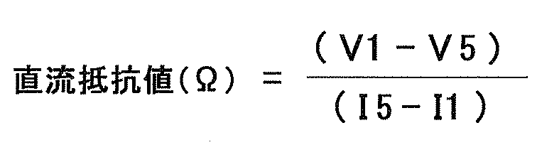
(曲げ試験)
実施例1~6および比較例1~4を試験片として、JIS K 5600-5-1に準拠して、円筒型マンドレル試験器(コーテック社製)を用いて曲げ試験を実施した。実施例1の試験片は、心棒の直径が1cmでも該試験片における電極活物質層に割れが生じず、また、集電体と電極活物質層の間にはがれも生じなかった。このことから、実施例1について、はがれ抵抗性を示す心棒の直径は、1cm未満であった。実施例2~6および比較例1~4の曲げ試験の結果を表2に示す。
実施例1~6および比較例1~4を試験片として、JIS K 5600-5-1に準拠して、円筒型マンドレル試験器(コーテック社製)を用いて曲げ試験を実施した。実施例1の試験片は、心棒の直径が1cmでも該試験片における電極活物質層に割れが生じず、また、集電体と電極活物質層の間にはがれも生じなかった。このことから、実施例1について、はがれ抵抗性を示す心棒の直径は、1cm未満であった。実施例2~6および比較例1~4の曲げ試験の結果を表2に示す。
(参照用電極板の調製)
次に、実施例1の曲げ特性の向上を確認するために、実施例1の参照用電極板を次に示すように調製した。
まず、シランカップリング剤を添加しなかったほかは実施例1における電極活物層形成液と同様に参照用電極板の電極活物質層液(以下、「参照用液」ともいう)を調整した。この参照用液を用いたこと以外は実施例1と同様に、非水電解液二次電池用電極板を作製し、これを参照用電極板とした。そして、上記参照用電極板を試験片として、実施例1を試験片とした場合と同様に円筒型マンドレル試験器を用いて曲げ試験を実施した。結果、はがれ抵抗性を示す心棒の直径は1cmであり、参照用電極板に比べて実施例1の曲げ特性が優れることが確認された。また、実施例1は、曲げ特性の向上により、電極活物質層が集電体から剥離し難くなっていることより、電極活物質層自体の密着性および集電体に対する電極活物質層の密着性が向上していることが確認された。
次に、実施例1の曲げ特性の向上を確認するために、実施例1の参照用電極板を次に示すように調製した。
まず、シランカップリング剤を添加しなかったほかは実施例1における電極活物層形成液と同様に参照用電極板の電極活物質層液(以下、「参照用液」ともいう)を調整した。この参照用液を用いたこと以外は実施例1と同様に、非水電解液二次電池用電極板を作製し、これを参照用電極板とした。そして、上記参照用電極板を試験片として、実施例1を試験片とした場合と同様に円筒型マンドレル試験器を用いて曲げ試験を実施した。結果、はがれ抵抗性を示す心棒の直径は1cmであり、参照用電極板に比べて実施例1の曲げ特性が優れることが確認された。また、実施例1は、曲げ特性の向上により、電極活物質層が集電体から剥離し難くなっていることより、電極活物質層自体の密着性および集電体に対する電極活物質層の密着性が向上していることが確認された。
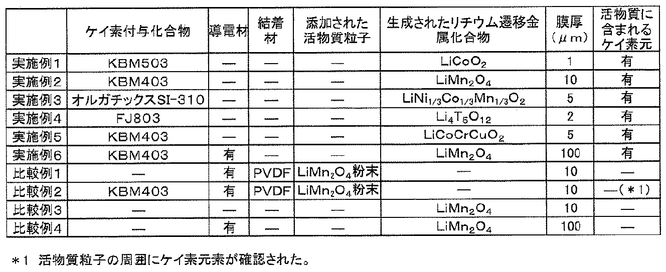
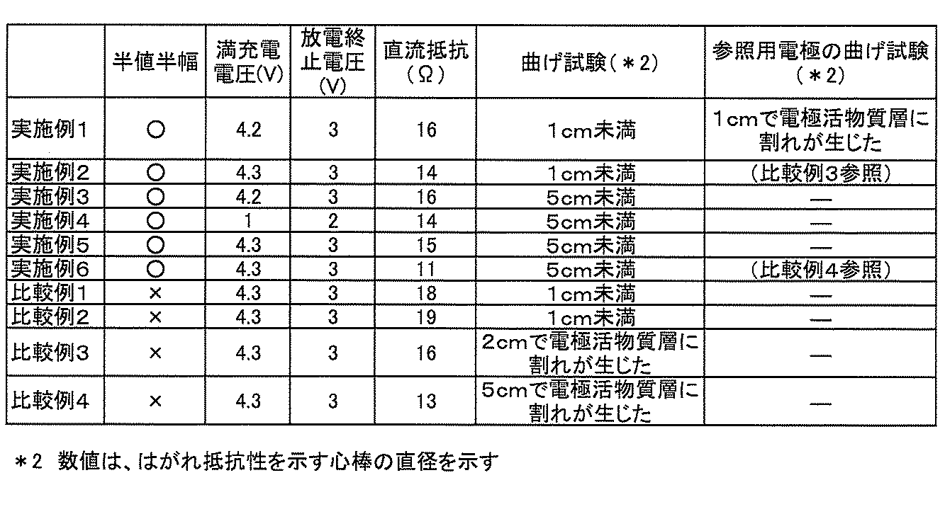
1、11 集電体
2、12 電極活物質層
3、13、16 活物質
4、14 空隙
10、20 非水電解液二次電池用電極板
17 緻密層
21 負極板
22 集電体
23 電極活物質層
24 セパレータ
25、26 外装
27 非水電解液
28 非水電解液二次電池
30 電池パック
31 リチウムイオン二次電池
32 正極端子
33 負極端子
34 保護回路基板
35 外部接続コネクタ
36a、36b 樹脂容器
37 端部ケース
38a、38b 外部接続用窓
2、12 電極活物質層
3、13、16 活物質
4、14 空隙
10、20 非水電解液二次電池用電極板
17 緻密層
21 負極板
22 集電体
23 電極活物質層
24 セパレータ
25、26 外装
27 非水電解液
28 非水電解液二次電池
30 電池パック
31 リチウムイオン二次電池
32 正極端子
33 負極端子
34 保護回路基板
35 外部接続コネクタ
36a、36b 樹脂容器
37 端部ケース
38a、38b 外部接続用窓
Claims (8)
- 集電体と、前記集電体に形成された電極活物質層とを備える非水電解液二次電池用電極板であって、
前記電極活物質層は、活物質同士が少なくとも部分的に接合することにより前記活物質が連続的に存在してなる層構造によって形成され、且つ、電解液が浸透可能な空隙を有する多孔質の空隙形成層を含み、
前記電極活物質層を構成する前記活物質が、リチウム挿入脱離反応可能なリチウム遷移金属複合酸化物、およびケイ素を含むことを特徴とする非水電解液二次電池用電極板。 - 集電体と、前記集電体に形成された電極活物質層とを備える非水電解液二次電池用電極板であって、
前記電極活物質層は、活物質同士が少なくとも部分的に接合することにより前記活物質が連続的に存在してなる層構造によって形成され、且つ、電解液が浸透可能な空隙を有する多孔質の空隙形成層を含み、
前記電極活物質層を構成する前記活物質は、リチウム挿入脱離反応可能なリチウム遷移金属複合酸化物を含み、
前記電極活物質層の赤外吸収スペクトルを測定したときに得られるSi-O結合の1000cm-1以上1100cm-1以下に現れるピークの半値半幅が、30cm-1以上90cm-1以下であることを特徴とする非水電解液二次電池用電極板。 - 正極板と、負極板と、前記正極板と前記負極板との間に設けられるセパレータと、非水溶媒を含む電解液とを少なくとも備えた非水電解液二次電池において、
前記正極板および前記負極板の少なくともいずれか一方が、請求項1または2に記載の非水電解液二次電池用電極板であることを特徴とする非水電解液二次電池。 - 収納ケースと、正極端子および負極端子を備える非水電解液二次電池と、過充電および過放電保護機能を有する保護回路とを少なくとも備え、前記収納ケースに前記非水電解液二次電池および前記保護回路が収納されて構成される電池パックにおいて、
前記非水電解液二次電池が、電極活物質を含む正極板と、負極板と、前記正極板と前記負極板との間に設けられるセパレータと、非水溶媒を含む電解液とを少なくとも備えた非水電解液二次電池であり、
前記正極板および前記負極板の少なくともいずれか一方が、請求項1または2に記載の非水電解液二次電池用電極板であることを特徴とする電池パック。 - リチウム元素含有化合物と、遷移金属元素含有化合物とが溶媒に溶解され、ケイ素元素含有化合物を含有する電極活物質層形成液を調製し、
前記電極活物質層形成液を集電体に塗布して塗膜を形成し、
前記塗膜が形成された集電体を、前記リチウム元素含有化合物、前記遷移金属元素含有化合物、および前記ケイ素元素含化合物の熱分解温度以上で加熱し、
リチウム挿入脱離反応可能なリチウム遷移金属複合酸化物を含む活物質で構成される電極活物質層を前記集電体に形成することを特徴とする非水電解液二次電池用電極板の製造方法。 - 前記ケイ素元素含有化合物が、有機系ケイ素含有化合物であることを特徴とする請求項5に記載の非水電解液二次電池用電極板の製造方法。
- 前記ケイ素元素含有化合物が、加水分解性基を有することを特徴とする請求項6に記載の非水電解液二次電池用電極板の製造方法。
- 前記ケイ素元素含有化合物がシランカップリング剤であることを特徴とする請求項7に記載の非水電解液二次電池用電極板の製造方法。
Applications Claiming Priority (4)
| Application Number | Priority Date | Filing Date | Title |
|---|---|---|---|
| JP2010080310 | 2010-03-31 | ||
| JP2010-080310 | 2010-03-31 | ||
| JP2011-067199 | 2011-03-25 | ||
| JP2011067199A JP5168525B2 (ja) | 2010-03-31 | 2011-03-25 | 非水電解液二次電池用電極板、非水電解液二次電池、電池パック、および非水電解液二次電池用電極板の製造方法 |
Publications (1)
| Publication Number | Publication Date |
|---|---|
| WO2011125734A1 true WO2011125734A1 (ja) | 2011-10-13 |
Family
ID=44762676
Family Applications (1)
| Application Number | Title | Priority Date | Filing Date |
|---|---|---|---|
| PCT/JP2011/058002 Ceased WO2011125734A1 (ja) | 2010-03-31 | 2011-03-30 | 非水電解液二次電池用電極板、非水電解液二次電池、電池パック、および非水電解液二次電池用電極板の製造方法 |
Country Status (2)
| Country | Link |
|---|---|
| JP (1) | JP5168525B2 (ja) |
| WO (1) | WO2011125734A1 (ja) |
Families Citing this family (4)
| Publication number | Priority date | Publication date | Assignee | Title |
|---|---|---|---|---|
| JP6074914B2 (ja) * | 2012-05-16 | 2017-02-08 | 大日本印刷株式会社 | 非水電解液二次電池用電極板、非水電解液二次電池、電池パック、及び非水電解液二次電池用電極板の製造方法 |
| JP6379655B2 (ja) * | 2014-05-15 | 2018-08-29 | Tdk株式会社 | リチウムイオン二次電池用負極活物質及びそれを有するリチウムイオン二次電池 |
| WO2020152119A1 (en) | 2019-01-25 | 2020-07-30 | Shell Internationale Research Maatschappij B.V. | An electric energy storage device |
| WO2023229299A1 (ko) * | 2022-05-24 | 2023-11-30 | 주식회사 엘지화학 | 리튬 이차 전지용 전극, 이의 제조 방법 및 이를 포함하는 리튬 이차 전지 |
Citations (5)
| Publication number | Priority date | Publication date | Assignee | Title |
|---|---|---|---|---|
| JPH0275158A (ja) * | 1988-09-08 | 1990-03-14 | Toyota Central Res & Dev Lab Inc | リチウム二次電池用複合正極およびその製造法 |
| JP2002319405A (ja) * | 2001-04-23 | 2002-10-31 | Toyota Motor Corp | リチウム二次電池 |
| JP2005078991A (ja) * | 2003-09-02 | 2005-03-24 | Nissan Motor Co Ltd | 非水電解質二次電池 |
| JP2007280830A (ja) * | 2006-04-10 | 2007-10-25 | Matsushita Electric Ind Co Ltd | 非水電解質二次電池用正極とその製造方法およびそれらを用いた非水電解質二次電池 |
| JP2010086712A (ja) * | 2008-09-30 | 2010-04-15 | Dainippon Printing Co Ltd | 非水電解液二次電池用電極板、非水電解液二次電池用電極板の製造方法、および非水電解液二次電池 |
Family Cites Families (1)
| Publication number | Priority date | Publication date | Assignee | Title |
|---|---|---|---|---|
| JP4852824B2 (ja) * | 2004-03-31 | 2012-01-11 | 日本電気株式会社 | リチウム二次電池用負極、その製造方法及びリチウム二次電池 |
-
2011
- 2011-03-25 JP JP2011067199A patent/JP5168525B2/ja not_active Expired - Fee Related
- 2011-03-30 WO PCT/JP2011/058002 patent/WO2011125734A1/ja not_active Ceased
Patent Citations (5)
| Publication number | Priority date | Publication date | Assignee | Title |
|---|---|---|---|---|
| JPH0275158A (ja) * | 1988-09-08 | 1990-03-14 | Toyota Central Res & Dev Lab Inc | リチウム二次電池用複合正極およびその製造法 |
| JP2002319405A (ja) * | 2001-04-23 | 2002-10-31 | Toyota Motor Corp | リチウム二次電池 |
| JP2005078991A (ja) * | 2003-09-02 | 2005-03-24 | Nissan Motor Co Ltd | 非水電解質二次電池 |
| JP2007280830A (ja) * | 2006-04-10 | 2007-10-25 | Matsushita Electric Ind Co Ltd | 非水電解質二次電池用正極とその製造方法およびそれらを用いた非水電解質二次電池 |
| JP2010086712A (ja) * | 2008-09-30 | 2010-04-15 | Dainippon Printing Co Ltd | 非水電解液二次電池用電極板、非水電解液二次電池用電極板の製造方法、および非水電解液二次電池 |
Also Published As
| Publication number | Publication date |
|---|---|
| JP5168525B2 (ja) | 2013-03-21 |
| JP2011228282A (ja) | 2011-11-10 |
Similar Documents
| Publication | Publication Date | Title |
|---|---|---|
| KR101762519B1 (ko) | 리튬 이차 전지 및 그 제조 방법 | |
| JP7029676B2 (ja) | 非水電解質二次電池用負極、非水電解質二次電池及び非水電解質二次電池用負極の製造方法 | |
| JP5999457B2 (ja) | リチウム二次電池およびその製造方法 | |
| JP5168525B2 (ja) | 非水電解液二次電池用電極板、非水電解液二次電池、電池パック、および非水電解液二次電池用電極板の製造方法 | |
| JP2012248436A (ja) | アルカリ金属イオン二次電池用電極板、アルカリ金属イオン二次電池、および電池パック | |
| JP2012109246A (ja) | 非水電解液二次電池用電極板、非水電解液二次電池、及び電池パック | |
| JP4972199B2 (ja) | 非水電解液二次電池用電極板、非水電解液二次電池用電極板の製造方法、非水電解液二次電池、および電池パック | |
| JP2012079651A (ja) | 非水電解液二次電池用電極板、非水電解液二次電池、および電池パック | |
| JP5168399B2 (ja) | 非水電解液二次電池用電極板、非水電解液二次電池、電池パック、及び非水電解液二次電池用電極板の製造方法 | |
| JP2012089249A (ja) | 非水電解液二次電池用電極板、非水電解液二次電池および電池パック | |
| JP2012190726A (ja) | 非水電解液二次電池用負極板、非水電解液二次電池、および電池パック | |
| JP2012094410A (ja) | 全固体二次電池、および全固体二次電池の製造方法 | |
| JP4695718B2 (ja) | 非水電解液二次電池 | |
| JP2012094351A (ja) | 非水電解液二次電池用正極板、非水電解液二次電池、および非水電解液二次電池用正極板の製造方法、並びに電池パック | |
| JP2012094409A (ja) | 非水電解液二次電池用電極板、その製造方法、非水電解液二次電池、および電池パック | |
| JP2012190727A (ja) | 非水電解液二次電池用電極板、非水電解液二次電池、および電池パック | |
| JP2012094408A (ja) | 非水電解液二次電池用電極板、非水電解液二次電池、および電池パック、並びに非水電解液二次電池用電極板の製造方法 | |
| JP2012079448A (ja) | 非水電解液二次電池用電極板、非水電解液二次電池用電極板の製造方法、非水電解液二次電池、および電池パック | |
| JP2011204488A (ja) | 非水電解液二次電池用正極板、非水電解液二次電池用正極板の製造方法、および非水電解液二次電池 | |
| JP2012089247A (ja) | 非水電解液二次電池用電極板、非水電解液二次電池および電池パック | |
| JP2011204489A (ja) | 非水電解液二次電池用正極板、非水電解液二次電池用正極板の製造方法、および非水電解液二次電池 | |
| JP2011204490A (ja) | 非水電解液二次電池用正極板、非水電解液二次電池用正極板の製造方法、および非水電解液二次電池 | |
| JP2012094338A (ja) | 非水電解液二次電池用電極板、非水電解液二次電池、及び電池パック | |
| JP2012094352A (ja) | 非水電解液二次電池用正極板、非水電解液二次電池、および非水電解液二次電池用正極板の製造方法、並びに電池パック | |
| JP2012089245A (ja) | 非水電解液二次電池用電極板、非水電解液二次電池および電池パック |
Legal Events
| Date | Code | Title | Description |
|---|---|---|---|
| 121 | Ep: the epo has been informed by wipo that ep was designated in this application |
Ref document number: 11765634 Country of ref document: EP Kind code of ref document: A1 |
|
| NENP | Non-entry into the national phase |
Ref country code: DE |
|
| 122 | Ep: pct application non-entry in european phase |
Ref document number: 11765634 Country of ref document: EP Kind code of ref document: A1 |