WO2011125528A1 - 放射線撮像装置 - Google Patents
放射線撮像装置 Download PDFInfo
- Publication number
- WO2011125528A1 WO2011125528A1 PCT/JP2011/057259 JP2011057259W WO2011125528A1 WO 2011125528 A1 WO2011125528 A1 WO 2011125528A1 JP 2011057259 W JP2011057259 W JP 2011057259W WO 2011125528 A1 WO2011125528 A1 WO 2011125528A1
- Authority
- WO
- WIPO (PCT)
- Prior art keywords
- detection unit
- radiation
- radiation detection
- unit
- housing
- Prior art date
- Legal status (The legal status is an assumption and is not a legal conclusion. Google has not performed a legal analysis and makes no representation as to the accuracy of the status listed.)
- Ceased
Links
Images








Classifications
-
- A—HUMAN NECESSITIES
- A61—MEDICAL OR VETERINARY SCIENCE; HYGIENE
- A61B—DIAGNOSIS; SURGERY; IDENTIFICATION
- A61B6/00—Apparatus or devices for radiation diagnosis; Apparatus or devices for radiation diagnosis combined with radiation therapy equipment
- A61B6/42—Arrangements for detecting radiation specially adapted for radiation diagnosis
- A61B6/4283—Arrangements for detecting radiation specially adapted for radiation diagnosis characterised by a detector unit being housed in a cassette
-
- A—HUMAN NECESSITIES
- A61—MEDICAL OR VETERINARY SCIENCE; HYGIENE
- A61B—DIAGNOSIS; SURGERY; IDENTIFICATION
- A61B6/00—Apparatus or devices for radiation diagnosis; Apparatus or devices for radiation diagnosis combined with radiation therapy equipment
- A61B6/42—Arrangements for detecting radiation specially adapted for radiation diagnosis
- A61B6/4208—Arrangements for detecting radiation specially adapted for radiation diagnosis characterised by using a particular type of detector
- A61B6/4233—Arrangements for detecting radiation specially adapted for radiation diagnosis characterised by using a particular type of detector using matrix detectors
-
- A—HUMAN NECESSITIES
- A61—MEDICAL OR VETERINARY SCIENCE; HYGIENE
- A61B—DIAGNOSIS; SURGERY; IDENTIFICATION
- A61B6/00—Apparatus or devices for radiation diagnosis; Apparatus or devices for radiation diagnosis combined with radiation therapy equipment
- A61B6/44—Constructional features of apparatus for radiation diagnosis
- A61B6/4429—Constructional features of apparatus for radiation diagnosis related to the mounting of source units and detector units
- A61B6/4452—Constructional features of apparatus for radiation diagnosis related to the mounting of source units and detector units the source unit and the detector unit being able to move relative to each other
-
- A—HUMAN NECESSITIES
- A61—MEDICAL OR VETERINARY SCIENCE; HYGIENE
- A61B—DIAGNOSIS; SURGERY; IDENTIFICATION
- A61B6/00—Apparatus or devices for radiation diagnosis; Apparatus or devices for radiation diagnosis combined with radiation therapy equipment
- A61B6/54—Control of apparatus or devices for radiation diagnosis
- A61B6/547—Control of apparatus or devices for radiation diagnosis involving tracking of position of the device or parts of the device
-
- A—HUMAN NECESSITIES
- A61—MEDICAL OR VETERINARY SCIENCE; HYGIENE
- A61B—DIAGNOSIS; SURGERY; IDENTIFICATION
- A61B6/00—Apparatus or devices for radiation diagnosis; Apparatus or devices for radiation diagnosis combined with radiation therapy equipment
- A61B6/54—Control of apparatus or devices for radiation diagnosis
- A61B6/548—Remote control of the apparatus or devices
Definitions
- the present invention relates to a radiation imaging apparatus, and more particularly to a radiation imaging apparatus provided with a flexible radiation detecting unit.
- photography was performed using the film or electronic cassette from which a magnitude
- electronic cassettes are expensive, it has been difficult in some cases to arrange a plurality of electronic cassettes of different sizes.
- an electronic cassette has been proposed in which the imaging area can be made variable according to the imaging site using a single flexible substrate as disclosed in JP 2009-205155 A. ing.
- Electronic cassettes can be used repeatedly, but they deteriorate with each use as they receive radiation. Specifically, the characteristics of the semiconductor deteriorate due to the radiation, and there is a concern that the detection sensitivity of the detector or the switching characteristics of the switching element may be deteriorated. Particularly in the electronic cassette as disclosed in Patent Document 1, the area near the outlet is used many times, and the degree of deterioration is different depending on the area even in one radiation detection unit. If there is a difference in the degree of deterioration depending on the area in one radiation detection unit, for example, when photographing a subject with a size that maximizes the radiation detection unit, the image quality difference in one image Was likely to occur.
- the present invention has been made in view of the above circumstances, and the size of the radiation detection unit and the area used are variable, and deterioration of the radiation detection unit due to repeated use does not concentrate on one area, and long-term use Aims to provide an electronic cassette that can
- a radiation imaging apparatus accommodates a flexible radiation detection unit, a first housing, a second housing, and a front radiation detection unit in the first housing, Alternatively, it has a first drive mechanism that is pulled out from the inside of the first housing, and a second drive mechanism that accommodates the radiation detection unit in the second housing or that is pulled out from the inside of the second housing.
- One end of the radiation detection unit is attached to the first drive mechanism, and the other end of the radiation detection unit is attached to the second drive mechanism.
- an automatic drive mechanism for automatically driving the first drive mechanism or the second drive mechanism to at least one of the first case and the second case, and the automatic drive mechanism are controlled.
- a control unit is provided.
- the radiation detection apparatus further includes a position detection unit that detects the position of the first casing and / or the position of the second casing with respect to the radiation detection unit.
- FIG. 1 is a perspective view of an electronic cassette according to Embodiment 1;
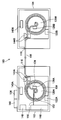
- FIG. 1 is a cross-sectional view of an electronic cassette according to Embodiment 1; It is a top view of a radiation detection part.
- It is a circuit block diagram of an electronic cassette.
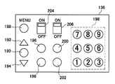
- It is a schematic diagram of an input part.
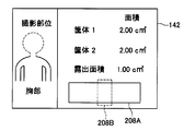
- It is a schematic diagram of a display part.
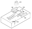
- 5 is a usage example of the electronic cassette according to the first embodiment.
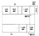
- These are a control example in which the radiation detection unit is used in one imaging direction, and a control example in which the radiation detection unit is used in the other imaging direction. It is an example of control which uses the same field of a radiation detection part in multiple times. This is an example of control in which the use area of the radiation detection unit is different each time.
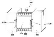
- FIG. 6 is a perspective view of an electronic cassette according to Embodiment 2;
- FIG. 10 is a diagram showing a state in which the electronic cassette according to the second embodiment is accommodated.
- FIG. 6 is a perspective view of an electronic cassette according to Embodiment 2; It is a figure showing the structure of a support stick. It is a figure showing the structure of a support stick.
- FIG. 5 is a diagram of a structure in which a motor drives a support bar. It is a cross-sectional schematic diagram shown to schematic structure of the radiation detection part of an indirect conversion system. It is sectional drawing which shows the schematic structure of a signal output part.
- FIG. 6 is a cross-sectional view showing a state in which the radiation detection unit is wound up by the winding unit so that the TFT substrate is on the inner side.
- It is sectional drawing which shows an example of a structure in the case of forming the scintillator of a radiation detection part by a columnar crystal.
- It is a top view which shows an example of a structure in the case of forming the scintillator of a radiation detection part with a columnar crystal.
- It is a graph which shows the relationship between the cumulative exposure dose of CsI, and a sensitivity.
- It is a top view which shows the structure of the radiation detection part which formed the drive circuit.
- FIG. 1 is an external perspective view of an electronic cassette 100 according to the present embodiment.
- the schematic configuration of the electronic cassette 100 will be described with reference to FIG.
- the diagonal lines in FIG. 1 represent the cross section of the housing.
- the electronic cassette 100 is housed in a housing 102 and a housing 104 having a substantially rectangular external shape, and is housed in the housing 102 or the housing 104, and detects radiation from a radiation source transmitted through an object, and a radiation image And a flexible radiation detection unit 106 for converting information into information.
- the radiation detection unit 106 is formed in a rectangular sheet shape having a sufficient length such that the imaging position can be changed and imaging can be performed a plurality of times. Specifically, the radiation detection unit 106 has a long side of about 5 meters and a short side of about 1 meter.
- a cylindrical winding portion 108 rotatably accommodated in the housing 102 is provided in the housing 102.
- a rotating shaft 112 is provided inside the winding unit 108 along the central axis of the winding unit 108.
- the rotating shaft 112 is longer than the central axis of the winding unit 108.
- Both ends of the rotating shaft 112 are exposed from the upper and lower surfaces of the cylindrical winding section 108 and are rotatably attached to the inner wall in the housing 102.
- the winding unit 108 rotates around the rotating shaft 112.
- the housing 104 there is a cylindrical winding portion 110 rotatably accommodated in the housing 104.
- the housing 102 has an opening 116
- the housing 104 has an opening 118.
- One end of the radiation detection unit 106 is fixed to the rotating shaft 112 through the opening 116 and the winding unit 108, and the other end is fixed to the rotating shaft 114 through the opening 118 and the winding unit 110.
- the electronic cassette 100 can accommodate the radiation detection unit 106 in the housing 102 or the housing 104 by winding the radiation detection unit 106 around the winding unit 108 or the winding unit 110. ing.
- the area of the radiation detection unit 106 exposed to the outside (hereinafter referred to as the exposed area) can be freely changed within the range of the area of the radiation detection unit 106.
- the position of the exposed area in the whole (hereinafter referred to as the exposed position) can also be changed.
- the user can freely determine the area of the radiation detection unit 106 used for imaging.
- both ends of the radiation detection unit 106 specifically, the area from the both ends to the opening 116 to the rotation axis 112 or the area from the opening 118 to the rotation axis 114 are exposed from the housing 102 or the housing 104 I can not let it go.
- a scale 166 is attached to the surface of the radiation detection unit 106. Thereby, the quantity which pulled out the radiation detection part 106 can be confirmed visually.
- FIG. 2 is a cross-sectional view of the housing 102.
- the configuration of the housing 102 will be described in detail with reference to FIG.
- the housing 102 is attached to a cylindrical take-up portion 108 having a hollow portion 120 inside, a rotation shaft 112 penetrating the take-up portion 108 along the central axis of the take-up portion 108, and a rotation shaft 112 Do not have a spring.
- the rotating shaft 112 is connected to the winding unit 108 via a circular member (not shown) provided on the upper and lower surfaces of the cylindrical winding unit 108. Both ends of the rotating shaft 112 are rotatably attached to the inner wall of the housing 102 via bearings.
- the winding unit 108 rotates around the rotation shaft 112 while providing a hollow portion inside.
- a motor 122A for controlling the rotation of the rotation shaft is attached to the rotation shaft 112.
- the rotation of the motor 122A causes the rotation shaft 112 to rotate, and the winding unit 108 is rotationally driven.
- the winding unit 108 has an opening 124 in the longitudinal direction.
- the radiation detection unit 106 is accommodated in the hollow portion 120 inside the winding unit 108 through the opening 124 and is fixed by being wound around the rotation shaft 112.
- An electronic circuit 126A is mounted at one end 106A of the radiation detection unit 106.
- the electronic circuit 126A is housed in the hollow portion 120.
- a display unit 142 and an input unit 136 are provided on the housing 102, and a winding amount detection sensor 140A for detecting the winding amount of the radiation detection unit 106 is provided in the housing 102.
- the input unit 136 receives, from the user, a winding instruction of the radiation detection unit 106, a withdrawal instruction of the radiation detection unit 106, an input of patient information, designation of an imaging region, and an input operation of an area exposed by the radiation detection unit 106.
- a known sensor can be used as the winding amount detection sensor 140A.
- the take-up amount detection sensor 140A calculates the extraction amount of the radiation detection unit 106 from the length of the radius of the take-up unit 108 and the rotation angle of the take-up unit 108, and outputs the calculated amount to the display unit 142.
- the display unit 142 receives the output from the winding amount detection sensor 140A, and displays the exposed area of the radiation detection unit 106.
- a stopper 144A for controlling the amount of extraction of the radiation detection unit 106 is provided near the opening 116 of the housing 102.
- the stopper 144 ⁇ / b> A sandwiches the radiation detection unit 106 from the upper surface and the lower surface to disable winding and drawing.
- the stopper 144 ⁇ / b> A can switch between the OFF state where the radiation detection unit 106 can be wound and pulled out and the ON state where winding and drawing can not be carried out.
- a removable battery 146 and an input / output interface 148 are accommodated.
- the battery 146 has an external terminal 150 extending to one end of the rotating shaft 112, and a brush 152 which is always in contact with the rotating shaft 112 is provided at the tip of the external terminal 150.
- the brush 152, the rotation shaft 112, the radiation detection unit 106, the electronic circuit 126A, the motor 122A, the input unit 136, the winding amount detection sensor 140A, the display unit 142, and the stopper 144A are electrically connected.
- the power from the battery 146 is supplied to the radiation detection unit 106, the electronic circuit 126A, the motor 122A, the input unit 136, the winding amount detection sensor 140A, the display unit 142 and the stopper 144A through the brush 152 and the rotating shaft 112. .
- a lead or copper plate (not shown) is disposed on the inner wall of the housing 102.
- the lead plate prevents damage to the radiation detection unit 106, the electronic circuit 126A, and the like housed in the housing 102 due to the radiation being applied to the housing 102.
- the configuration of the case 104 is substantially the same as the case 102.
- the motor 122 B, the electronic circuit 126 B, the winding amount detection sensor 140 B, and the stopper 144 B in the housing 104 are electrically connected to the electronic circuit 126 A and the battery 146 via the radiation detection unit 106.
- the battery 146 inside the housing 102 can supply power to the inside of the housing 104, and it is not necessary to provide the battery in the housing 104.
- FIG. 3 is a plan view of the radiation detection unit 106.
- the configuration of the radiation detection unit 106 will be described with reference to FIG.
- the radiation detection unit 106 has flexibility.
- the radiation detection unit 106 includes a radiation conversion unit 156 in which a large number of pixels 154 are formed, and a first flexible wiring unit 160 in which a large number of gate lines 158 wired to the large number of pixels 154 are formed. And a second flexible wiring portion 164 in which a large number of signal lines 162 wired to a large number of pixels 154 are formed.
- FIG. 4 is a block diagram of a circuit configuration of the radiation detection unit 106 and its peripheral configuration. The detailed configuration of the radiation detection unit 106 will be described with reference to FIG.
- the radiation detection unit 106 has an electronic circuit 126A at its end.
- the electronic circuit 126A includes a cassette control unit 128, a reading circuit 130, a transmitting / receiving unit 132, an image memory 134, an input unit 136, an image storage unit 137, a photographing area storage unit 138, and a use status storage unit 139.
- the cassette control unit 128 drives the circuit of the radiation detection unit 106, drives the electronic circuit 126A, drives the rotary drive electronic circuit 126B, drives the motor 122A, drives the motor 122B, controls the ON / OFF of the stopper 144A, and the stopper 144B. Control the ON / OFF of the.
- the readout circuit 130 reads out the radiation image information converted by the radiation detection unit 106.
- the transmitting and receiving unit 132 transmits and receives a signal including the radiation image information read by the reading circuit 130.
- the image memory 134 stores the radiation image information read by the reading circuit 130.
- the image storage unit 137 is a memory capable of writing and reading.
- the image storage unit 137 stores the radiographed radiograph, information on the radiographed patient, and the like.
- the imaging area storage unit 138 stores the operation program of the electronic cassette 100 and the value of the exposure area of the radiation detection unit 106 corresponding to each imaging site specified by the input unit 136.
- the usage status storage unit 139 stores the usage status of the radiation detection unit 106. Specifically, the use status storage unit 139 stores the number of times of imaging of the region of the radiation detection unit 106 used in the previous imaging and the plurality of regions into which the radiation detection unit 106 is divided. Based on the use status of the radiation detection unit 106 stored in the use status storage unit 139, the cassette control unit 128 controls so that only the same area is not used repeatedly for imaging.
- the image storage unit 137, the photographing area storage unit 138, and the use status storage unit 139 can use known storage devices such as a hard disk.
- the input / output interface 148 exchanges signals including radiation image information with the transmission / reception unit 132.
- the exchange of signals between the transmission / reception unit 132 and the input / output interface 148 can be performed using radio waves with a frequency of 3 kHz to 3 T (tera) Hz or less, or infrared light.
- signal exchange can be realized by providing transmitting / receiving antennas in the transmitting / receiving unit 132 and the input / output interface 148, respectively.
- the photoelectric conversion layer 168 is made of a material such as amorphous selenium (a-Se) that senses radiation and generates charge.
- the photoelectric conversion layer 168 is disposed on an array of thin film transistors (TFTs) 170 arranged in a matrix.
- TFTs thin film transistors
- the photoelectric conversion layer 168 stores the generated charges in the storage capacitor 172, and then turns on the TFTs 170 sequentially through the gate line 158 for each row to read out the charges as an image signal.
- FIG. 4 only the connection relationship between one pixel 154 including the photoelectric conversion layer 168 and the storage capacitor 172 and one TFT 170 is shown in detail, and the configuration of the other pixels is omitted.
- gate lines 158 extending in parallel to the row direction and signal lines 162 extending in parallel to the column direction are connected.
- Each gate line 158 is connected to the line scan drive unit 174 of the readout circuit 130 via the first flexible wiring unit 160.
- Each signal line 162 is connected to the multiplexer 176 of the readout circuit 130 via the second flexible wiring portion 164.
- Control signals Von and Voff for on / off controlling the TFTs 170 arranged in the row direction are supplied from the line scan drive unit 174 to the gate line 158.
- the line scan driver 174 includes a plurality of switches SW1 for switching the gate line 158 and a first address decoder 178 for outputting a selection signal for selecting one of the switches SW1.
- An address signal is supplied from the cassette control unit 128 to the first address decoder 178. Further, the charge held in the storage capacitor 172 of each pixel 154 flows out to the signal line 162 through the TFTs 170 arranged in the column direction. This charge is amplified by the amplifier 180 of the read circuit 130.
- the multiplexer 180 is connected to the amplifier 180 via the sample and hold circuit 182 of the read circuit 130.
- the multiplexer 176 includes a plurality of switches SW2 for switching the signal line 162 and a second address decoder 184 which outputs a selection signal for selecting one of the switches SW2.
- An address signal is supplied from the cassette control unit 128 to the second address decoder 184.
- the multiplexer 176 is connected to the A / D converter 186 of the read circuit 130.
- the radiation image information is converted into a digital signal by the A / D converter 186 and stored in the image memory 134 via the cassette control unit 128.
- the radiation image information stored in the image memory 134 is transmitted to a portable information terminal (not shown) or the like via the transmission / reception unit 132 and the input / output interface 148.
- the radiation image information can also be stored in the image storage unit 137.
- the radiation image information is data compressed as needed.
- FIG. 5 is a schematic view of the input unit 136.
- the input unit includes a menu button 188, a determination button 190, an upper button 192, a lower button 194, a take-up button 196 for winding the radiation detection unit 106 to the housing 102, and for extracting the radiation detection unit 106 from the housing 102.
- the menu button 188 is a button for displaying a shooting menu.
- a shooting menu is displayed on the display unit 142.
- the imaging menu includes an imaging area specification mode based on an imaging region, a direct imaging area specification mode, an imaging area specification mode from a display view, and a patient information input mode. Selection of the photographing menu is performed using the upper button 192, the lower button 194 and the determination button 190.
- the user can designate a site to be imaged from among the chest, head, abdomen, arms, legs, legs and the like.
- the cassette control unit 128 reads out the imaging area corresponding to each site stored in advance in the imaging area storage unit 138.
- the user can input a numerical value and input the area using the ten key 198.
- the direct specification mode of the imaging area is used when it is desired to select an imaging area of a size that can not be handled only by the specification of a part.
- the exposure area and the exposure position are manually adjusted from the whole area view of the radiation detection unit 106 displayed on the display unit 142, the exposure area and the exposure position.
- the user can freely designate the exposure area and the exposure position of the radiation detection unit 106.
- the user can use the ten keys 198 to input patient information.
- the drawing button 200 for drawing out the radiation detection unit 106 from the case 200 and the case 104 can specify the winding operation and the drawing operation of the radiation detection unit 106 with respect to the case 102 or the case 104.
- the size of the exposed area can be adjusted by using it when it is desired to increase or decrease the exposed area.
- the ON / OFF switching switch 204 for the stopper 144A of the housing 102 and the ON / OFF switching switch 206 for the stopper 144B of the housing 104 manually turn ON / OFF the stoppers 144A and 144B provided on the housing 102 and the housing 104 It can be switched by. By turning off the changeover switch 204 or the changeover switch 206, the radiation detection unit 106 can be manually pulled out from the housing 102 or the housing 104.
- FIG. 6 is a display example of the display unit 142.
- the display unit 142 displays the designated imaging region, the housing area of the radiation detection unit 106 in the housing 102 and the housing 104, the entire area 208A of the radiation detection unit 106, the exposure area, and the exposure position 208B.
- the numerical value of the area wound in each case is displayed on the display unit 142.
- the display of the display unit 142 can also be used to indicate how many times the area is wound, in consideration of the imaging region, such as the chest x times and the foot y times. Specifically, by dividing the area wound in each case by the area corresponding to each part, it is calculated how many areas of the area corresponding to each imaging part are wound. be able to. As described above, when the display corresponds to each imaging site, the user can easily grasp the area wound in each housing intuitively.
- the radiation detection unit 106 When the user does not use the electronic cassette 100, the radiation detection unit 106 is wound around the housing 102 or the housing 104, and the electronic cassette 100 is stored in a state where the exposed area of the radiation detection unit 106 becomes 0 Called).
- the user turns on the power and inputs patient information at the input unit 136. Specifically, the patient's name or ID to be measured is input. Subsequently, the exposed area of the radiation detection unit 106 is set by the input unit 136. For example, when the imaging region is designated by the input unit 136, the cassette control unit 128 reads the exposure area corresponding to the designated imaging region from the imaging area storage unit 138. The cassette control unit 128 has an exposed area corresponding to the imaging region read from the imaging area storage unit 138, an area of the radiation detection unit 106 wound around the winding unit 108, and a radiation wound around the winding unit 110.
- the angle at which the winding unit 110 and the winding unit 108 should rotate is calculated.
- the exposure position of the radiation detection unit 106 is changed by winding up and pulling out the radiation detection unit 106 in one pulling direction.
- the angle at which the winding unit 108 or the winding unit 110 rotates is calculated based on the exposed area corresponding to the imaging region and the radius of the winding unit 108 or the winding unit 110.
- the cassette control unit 128 gives a command to turn off the stopper, and gives a rotation command to the motor by the calculated angle.
- the cassette control unit After rotation of the motor is completed, the cassette control unit gives a command to turn on the stopper to disable the winding and drawing of the radiation detection unit 106. In this manner, the cassette control unit 128 rotates the winding unit 108 to adjust the exposed area of the radiation detection unit 106 to be the same as the exposed area read from the imaging area storage unit 138.
- FIG. 7 is a schematic view of the electronic cassette 100 in use.
- FIG. 7 shows the patient 210 lying on the bed 214 and taking the chest of the patient 210.
- the electronic cassette 100 is placed between the patient 210 and the bed 214.
- the electronic cassette 100 is placed so that the radiation detection unit 106 is located between the chest of the patient 210 and the bed 214. Radiation is irradiated from the radiation irradiating unit 212 on the upper side of the patient to the radiation detecting unit 106 through the patient 210 to perform imaging.
- the radiation transmitted through the patient 210 is converted into an electrical signal by the photoelectric conversion layer 168 of each of the pixels 154 constituting the exposed radiation detection unit 106, and the electrical signal is held as charge in the storage capacitor 172.
- charge information which is radiation image information of the patient 210 held in each storage capacitor 172 is read out according to the address signal supplied from the cassette control unit 128 to the line scan drive unit 174 and the multiplexer 176.
- the first address decoder 178 of the line scan drive unit 174 outputs a selection signal according to the address signal supplied from the cassette control unit 128 to select one of the switches SW 1 and select one of the TFTs 170 connected to the corresponding gate line 158.
- the control signal Von is supplied to the gate.
- the second address decoder 184 of the multiplexer 118 outputs a selection signal according to the address signal supplied from the cassette control unit 128 to sequentially switch the switch SW2, and is connected to the gate line 158 selected by the line scan drive unit 174.
- the radiation image information which is the charge information held in the storage capacitance 172 of each pixel 154 is sequentially read out via the signal line 162.
- the radiation image information read out from the storage capacitance 172 of each pixel 154 connected to the selected gate line 158 is amplified by each amplifier 180, then sampled by each sample and hold circuit 182, and is transmitted via the multiplexer 176.
- the signal is supplied to an A / D converter 186 and converted into a digital signal.
- the radiation image information converted into the digital signal is temporarily stored in the image memory 134 of the cassette control unit 128.
- the first address decoder 178 of the line scan drive unit 174 sequentially switches the switch SW1 in accordance with the address signal supplied from the cassette control unit 128, and is held in the storage capacitance 172 of each pixel 154 connected to each gate line 158.
- Radiation image information which is charge information is read out via the signal line 162.
- the read radiation image information is stored in the image memory 134 via the multiplexer 176, the A / D converter 186 and the cassette control unit 134.
- the cassette control unit 128 specifies the position of the radiation detection unit 106 used for imaging. Specifically, the exposed area and the exposed position of the radiation detection unit 106 are specified from the values of the winding amount detection sensors of the housing 102 and the housing 104.
- the cassette control unit 128 stores the identified exposure area and exposure position in the usage status storage unit 139.
- the cassette control unit 128 stores the number of times of use for each exposure position of the radiation detection unit 106 in the use status storage unit 139. Specifically, the entire area of the radiation detection unit 106 is divided in 1 cm steps in the direction in which the radiation detection unit 106 is pulled out, and the area used from the values of the winding amount detection sensors of the case 102 and the case 104 is Identify and store the number of times of use of the identified area by one. In this manner, the radiation detection unit 106 can store the number of times of use in 1 cm increments in the pull-out direction.
- the radiation image information stored in the image memory 134 is subjected to compression processing, and then transmitted to the image storage unit 137 via wireless communication via the storage or transmission / reception unit 132 and the input / output interface 148 to the portable information terminal.
- the cassette control unit 128 controls the winding unit 108 and the winding unit 110 so that an area different from the area used in the previous imaging, which is stored in the use status storage unit 139, is exposed. Control the rotation.
- the motor 122A and the motor 122B are rotationally driven at the same speed, and only the area used in the previous imaging is wound Alternatively, by pulling out, only the exposure position is changed without changing the exposed area.
- the exposure area used in the previous imaging differs from the exposure area used in the next imaging, the exposure area is made different by differentiating the speed or rotational speed of the rotational drive of the motor 122A and the motor 122B.
- the cassette control unit 128 reduces the amount of rotation of the motor on the pullout side to less than the amount of rotation of the motor on the windup side. Control is performed such that the stopper on the withdrawal side is turned ON when it has become.
- the user presses a winding button 196 for winding the radiation detection unit 106 in the housing 102 or a winding button 198 for winding the radiation detection unit 106 in the housing 104.
- the cassette control unit 128 issues an instruction to turn off the stopper and then issues a winding instruction to the motor in the housing 102 or the housing 104, and the radiation detection unit
- the winding unit 106 is wound around the winding unit 108 or the winding unit 110 to be in an accommodated state.
- the electronic cassette 100 performs radiation detection using radiation because the exposure area and the exposure position of the radiation detection unit 106 are variable and controlled to use an exposure position different from the previous exposure position. Deterioration of parts does not concentrate on the same area.
- FIG. 8 is a schematic view of the radiation detection unit 106.
- the electronic cassette 100 stores the exposure area of the radiation detection unit 106, the exposure position, and the number of times of use for each exposure position in the use status storage unit 139 for each imaging, and ends the imaging.
- the electronic cassette 100 receives an input operation of patient information and an exposure area from the user every time imaging is completed.
- the cassette control unit 128, which has received designation of patient information and exposed area from the user, has the radiation detection unit 106 wound around only one winding unit (referred to as winding unit A) at first. Pull out and use in order to pull out. In this case, the area used in the previous shooting is controlled so as not to be exposed to the outside in the next shooting. If the area designated by the user is larger than the area wound on the winding unit A (in the case of the n-th time in FIG. 8), the cassette control unit 128 pulls out all from the winding unit A, and the other The take-up unit (referred to as take-up unit B) is wound or pulled out to make the exposed area of the radiation detection unit 106 equal to the designated exposed area (FIG. 8).
- take-up unit B The take-up unit
- the exposed area designated by the user is exposed.
- the radiation detection unit 106 is used sequentially from the end, it is possible to cope with cases where imaging is desired with different areas for each imaging, and the usage status of the radiation detection unit 106 can be averaged.
- the exposure area and the exposure position of the radiation detection unit 106 can be changed. is there. Since the electronic cassette 100 stores the area of the radiation detection unit 106 used for imaging and controls to expose the exposure position different from the exposure position used immediately before, the deterioration due to radiation concentrates on the same exposure position There is no longer. In addition, since the electronic cassette 100 winds up the radiation detection unit 106 when not in use and puts it in the storage state, the electronic cassette 100 can be made compact and convenient to carry.
- the exposure area and the exposure position of the radiation detection unit 106 can be automatically adjusted.
- the two motors can be quickly wound up to be changed to the storage state quickly.
- the radiation detection unit 106 is a rectangular sheet as in the present embodiment
- the length of the short side is constant, and therefore, the area can be calculated by considering only the change in length in the winding direction. Therefore, the calculation of the area is simplified, and the control of the rotation of the motor is easy.
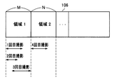
- FIG. 9 is a diagram schematically depicting the radiation detection unit.
- the cassette control unit 128 controls the rotation of the winding unit 108 and the winding unit 110 so as to start use from the region 1 shown in FIG. 9, adjusts the exposed area and position, and turns on the stopper.
- the arrows in the figure represent the width used in each shooting.
- the cassette control unit 128 rotates the winding unit 108 and the winding unit 110 so that the area 1 of width M corresponding to the input exposed area is exposed to the outside. .
- the cassette control unit 128 turns off the stopper. Then, the input of the exposed area from the user is accepted.
- the cassette control unit 128 turns the stopper ON by controlling the rotation of the winding unit 108 and the winding unit 110 such that the region 2 having the width N corresponding to the exposure area input by the user is exposed to the outside. If imaging is performed three times in area 2, area 3 is used.
- the electronic cassette 100 is stored in a case where the stopper is OFF or not provided, and only one stopper is ON. By controlling so as not to change the currently used position. By controlling in this manner, the exposure position of the radiation detection unit 106 can be stored without being changed. Therefore, even when it is desired to carry or store suddenly during shooting, the used area can be kept in a fixed state while being fixed.
- the use of 3 times was mentioned as an example here, this is not restricted to 3 times.
- the present invention is not limited to changing the area based on the number of times of imaging.
- a function of measuring the cumulative dose may be provided at a plurality of locations of the radiation detection unit 106, and the region to be used may be changed based on the cumulative dose.
- the cumulative radiation dose the same exposure position is used multiple times, and when the exposure position reaches a preset dose, a command is issued from the cassette control unit 128, the stopper is turned off, and the radiation detection unit 106 is It is controlled to be able to change the position.
- the use area can be changed when the cumulative radiation dose reaches a predetermined value, and the cumulative radiation dose of the radiation detection unit 106 can be used so as to be substantially equal overall.
- the cumulative radiation dose may not necessarily be measured by the function of detecting the cumulative dose.
- the cassette control unit 128 may communicate with the X-ray source to obtain an approximate value of the accumulated dose in correspondence with the exposure region of the radiation detection unit 106.
- FIG. 10 is a diagram schematically depicting the radiation detection unit.
- the hatched and dotted area in FIG. 10 represents the area used for imaging.
- the radiation detection unit 106 is equally divided by the width L, and the exposure area in each imaging is equal.
- the area immediately to the right is used for each shooting regardless of how much area is used in one shooting. It is assumed that the use is started from the area at the left end shown in FIG. 10, and that the shaded portion in FIG. 10 is used in the first shooting.
- the cassette control unit 128 drives the winding unit 108 and the winding unit 110 so that the region on the right side set in advance is exposed. Even after the second shooting, as in the case of the first shooting, the region next to the right is exposed regardless of whether the entire region is used or not. If this is repeated and the area at the right end is used at the n + 1-th time, the area used at the n-th time is used in the next photographing. In the next shooting, the area used in the n-1st shooting is used. As described above, when the radiation detection unit 106 is used, the previously used area is not used in the next imaging, and the use status can be dispersed. In addition, since the exposed area is equal for each photographing, the control of the rotation of the motor and the winding unit by the cassette control unit 128 is the same control each time, and the processing speed is improved.
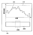
- FIG. 11 is a display example of the display unit 142.
- a graph in which the horizontal axis represents the area of the radiation detection unit 106 and the vertical axis represents the number of times of use of the radiation detection unit 106 in the upper part of the entire area 208A of the radiation detection unit 106 and the exposed area and exposure position 208B is displayed.
- 216 is displayed on the display unit 142. The graph 216 displays the results of storing the number of times of use of the radiation detection unit 106 in 1 cm increments in a graph.
- the dotted line 218 represents the upper limit of the recommended number of times of use of the radiation detection unit 106.
- the user can look at the graph 216 and select an exposure position that is used less frequently. In particular, when the user used last time and the user used this time are different, it is memorized which area the user used last time used, so by looking at the graph 216, the usage status of the radiation detection unit 106 can be grasped at a glance can do. Furthermore, when the display unit 142 displays the usage status of each user in a color-coded manner, it is possible to grasp which area each user is using preferentially.
- the user designates the imaging site or the area to be used for imaging
- the electronic cassette 100 automatically determines the optimum exposure position for the imaging site or the area to be used for imaging, exposing the radiation detection unit 106 to the outside. It may be controlled to Specifically, from the exposed area determined in accordance with the designated imaging region or area, and the number of times of use stored for each area of the radiation detection unit 106 by the cassette control unit 128, An area where the total number of times of use when the exposure area is used is the smallest is determined as an exposure position. For example, when imaging is performed with a drawing width of 10 cm in the drawing direction, the cassette control unit 128 sums and stores the number of uses for 10 cm from the left end of the entire region of the radiation detection unit 106.
- the cassette control unit 128 shifts the calculated area to the right by 1 cm, adds up the number of times of use, and stores it.
- the cassette control unit 128 performs this operation in order, and sums up and stores the number of times of use for each area up to the right end.
- the cassette control unit 128 determines an area where the total number of times of use is the smallest as the exposure position.
- the cassette control unit 128 controls the rotation of the winding unit 108 and the winding unit 110 so that the determined exposure position is exposed. As described above, when the cassette control unit 128 automatically determines the exposure position where the number of times of use is small, it is possible to average the number of times of use of the radiation detection unit 106 for each area without particular awareness of the user.
- the cassette control unit 128 may determine that the area exceeding the upper limit of the recommended number of times of use is unusable, and may control so as not to be exposed to the outside. This control prevents the user from using an area that may cause degradation in image quality.
- the cassette control unit 128 strictly grasps the use condition of the radiation detection unit 106, and controls to use the area with the least number of times of use. Also in the radiation detection unit 106 in which the bias of the situation has occurred, the usage situation can be averaged. As a result, even in the radiation detection unit 106 in which the image quality is different for each area, the image quality can be made substantially the same.
- the radiation detection unit 106 is a so-called direct conversion type that uses a solid-state detection element that converts radiation into an electrical signal, but the radiation detection unit 106 is not necessarily required if radiation image information is obtained. It is not limited to the direct conversion type.
- an indirect conversion type using a scintillator that once converts radiation into visible light and a solid detection element that converts visible light into an electrical signal may be used.
- a scintillator a phosphor having GOS (Gd2O2S: Tb) or CsI: Tl as a base can be used.
- a plastic cinch may be used as the scintillator.
- CMOS complementary metal-oxide-semiconductor
- the configuration in the case where the radiation detection unit 106 is an indirect conversion system will be described.
- the portions corresponding to the configurations (FIGS. 1 to 4) of the electronic cassette 100 and the radiation detection unit 106 of the first embodiment will be described with the same reference numerals.
- FIG. 17 is a schematic cross-sectional view schematically showing the configuration of three pixels 154 of the indirect conversion type radiation detection unit 106. As shown in FIG.
- a signal output unit 402, a sensor unit 403, and a scintillator 404 are sequentially stacked on a flexible insulating substrate 400.
- the signal output unit 402 and the sensor unit 403 constitute a pixel 154.
- a plurality of pixels 154 are arrayed on the substrate 400, and the signal output unit 402 and the sensor unit 403 in each pixel 154 are configured to have an overlap.
- the scintillator 404 is formed on the sensor unit 403 via the transparent insulating film 406, and is formed by depositing a phosphor that converts incident radiation into light and emits light. By providing such a scintillator 404, the radiation transmitted through the subject is absorbed and emitted.
- the wavelength range of light emitted by the scintillator 404 is preferably a visible light range (wavelengths of 360 nm to 830 nm). Furthermore, in order to enable monochrome imaging by the radiation detection unit 106, it is more preferable to include a green wavelength range.
- the phosphor used for the scintillator 404 preferably contains cesium iodide (CsI), and the emission spectrum at X-ray irradiation is in the range of 420 nm to 700 nm It is particularly preferred to use CsI (Tl).
- CsI cesium iodide
- Tl The emission peak wavelength of CsI (Tl) in the visible light range is 565 nm.
- the scintillator 404 may be formed by vapor deposition on a vapor deposition substrate, for example, in the case of forming a columnar crystal such as CsI (Tl).
- a columnar crystal such as CsI (Tl)
- an Al plate is often used in terms of X-ray transmittance and cost, but is not limited thereto.
- GOS is used as the scintillator 404
- the scintillator 404 may be formed by applying GOS without using a deposition substrate.
- the sensor unit 403 includes an upper electrode 410, a lower electrode 412, and a photoelectric conversion film 414 disposed between the upper and lower electrodes.
- the upper electrode 410 is preferably made of a conductive material that is transparent to at least the emission wavelength of the scintillator 404. Specifically, for the upper electrode 410, it is preferable to use a transparent conductive oxide (TCO; Transparent Conducting Oxide) which has a high transmittance to visible light and a small resistance value. Although a metal thin film of Au or the like can be used as the upper electrode 410, TCO is preferable because the resistance value tends to increase if it is intended to obtain a transmittance of 90% or more.
- TCO transparent Conducting Oxide
- the upper electrode 410 may have a single-plate configuration common to all the pixels 154 or may be divided for each pixel 154.
- the photoelectric conversion film 414 absorbs the light emitted from the scintillator 404 and generates a charge according to the absorbed light.
- the photoelectric conversion film 414 may be formed of a material which generates a charge by being irradiated with light, and can be formed of, for example, amorphous silicon, an organic photoelectric conversion material, or the like.
- the photoelectric conversion film 414 containing amorphous silicon can have a broad absorption spectrum and can absorb light emitted by the scintillator 404.
- the photoelectric conversion film 414 containing an organic photoelectric conversion material has a sharp absorption spectrum in the visible region, and electromagnetic waves other than light emitted by the scintillator 404 are hardly absorbed by the photoelectric conversion film 414. Therefore, noise generated by absorption of radiation such as X-rays by the photoelectric conversion film 414 can be effectively suppressed.
- the absorption peak wavelength of the organic photoelectric conversion material constituting the photoelectric conversion film 414 be closer to the emission peak wavelength of the scintillator 404 in order to absorb the light emitted by the scintillator 404 most efficiently.
- the absorption peak wavelength of the organic photoelectric conversion material matches the emission peak wavelength of the scintillator 404, but if the difference between the two is small, it is possible to sufficiently absorb the light emitted from the scintillator 404.
- the difference between the absorption peak wavelength of the organic photoelectric conversion material and the emission peak wavelength for radiation of the scintillator 404 is preferably 10 nm or less, and more preferably 5 nm or less.
- Examples of the organic photoelectric conversion material capable of satisfying such conditions include quinacridone organic compounds and phthalocyanine organic compounds.
- quinacridone organic compounds since the absorption peak wavelength of quinacridone in the visible region is 560 nm, the difference between the peak wavelengths can be made within 5 nm by using quinacridone as the organic photoelectric conversion material and CsI (Tl) as the material of the scintillator 404 It becomes. Therefore, the amount of charge generated in the photoelectric conversion film 414 can be almost maximized.
- the electromagnetic wave absorption / photoelectric conversion site in the indirect conversion type radiation detection unit 106 includes an organic photoelectric conversion film 414 sandwiched between a pair of lower electrode 412 and upper electrode 410 and the lower electrode 412 and upper electrode 410. It can be configured by layers. More specifically, this organic layer is a site that absorbs electromagnetic waves, a photoelectric conversion site, an electron transport site, a hole transport site, an electron blocking site, a hole blocking site, a crystallization prevention site, an electrode, and an interlayer contact improvement It can be formed by stacking or mixing parts or the like.
- the organic layer preferably contains an organic p-type compound or an organic n-type compound.
- the organic p-type semiconductor is a donor type organic semiconductor (compound) mainly represented by a hole transporting organic compound, and refers to an organic compound having a property of easily giving an electron. More specifically, an organic p-type semiconductor (compound) refers to an organic compound having a smaller ionization potential when used in contact with two organic materials. Therefore, as the donor organic compound, any organic compound having an electron donating property can be used.
- the organic n-type semiconductor (compound) is an acceptor-type organic semiconductor (compound) mainly represented by an electron transporting organic compound, and refers to an organic compound having a property of easily accepting an electron. More specifically, the organic n-type semiconductor (compound) refers to an organic compound having a larger electron affinity when used in contact with two organic compounds. Therefore, as the acceptor type organic compound, any organic compound can be used as long as it is an electron-accepting organic compound.
- the materials applicable as the organic p-type semiconductor and the organic n-type semiconductor, and the configuration of the photoelectric conversion film 414 are described in detail in JP 2009-32854 A, and thus the description thereof is omitted.
- the photoelectric conversion film 414 may further be formed by containing a fullerene or a carbon nanotube.
- the thickness of the photoelectric conversion film 414 is preferably as large as possible in terms of absorbing the light from the scintillator 404. However, if the thickness of the photoelectric conversion film 414 is increased to a certain extent or more, the intensity of the electric field generated in the photoelectric conversion film 414 is reduced by the bias voltage applied from both ends of the photoelectric conversion film 414 and the charge can not be collected.
- the thickness of the conversion film 414 is preferably 30 nm or more and 300 nm or less.
- the thickness of the photoelectric conversion film 414 is more preferably 50 nm or more and 250 nm or less, and particularly preferably 80 nm or more and 200 nm or less.
- the photoelectric conversion film 414 has a single-plate configuration common to all the pixels 154, but the photoelectric conversion film 414 may be divided for each pixel 154.
- the lower electrode 412 is a thin film divided for each pixel 154.
- the lower electrode 412 can be made of a transparent or opaque conductive material, and aluminum, silver or the like can be suitably used for the lower electrode 412.
- the thickness of the lower electrode 412 can be, for example, 30 nm or more and 300 nm or less.
- one of charges (holes and electrons) generated in the photoelectric conversion film 414 is moved to the upper electrode 410 by applying a predetermined bias voltage between the upper electrode 410 and the lower electrode 412.
- the other can be moved to the lower electrode 412.
- a wire is connected to the upper electrode 410, and a bias voltage is applied to the upper electrode 410 through the wire. Further, it is assumed that the polarity of the bias voltage is determined such that the electrons generated in the photoelectric conversion film 414 move to the upper electrode 410 and the holes move to the lower electrode 412, but the polarity is opposite. It is good.
- the sensor unit 403 constituting each pixel 154 may include at least the lower electrode 412, the photoelectric conversion film 414, and the upper electrode 410. In order to suppress an increase in dark current, it is preferable to provide at least one of the electron blocking film 416 and the hole blocking film 418 in the sensor unit 403, and it is more preferable to provide both.
- the electron blocking film 416 can be provided between the lower electrode 412 and the photoelectric conversion film 414. Accordingly, when a bias voltage is applied between the lower electrode 412 and the upper electrode 410, it is possible to suppress an increase in dark current due to the injection of electrons from the lower electrode 412 to the photoelectric conversion film 414.
- an electron donating organic material can be used.
- the material used for the electron blocking film 416 may be selected according to the material of the adjacent electrode, the material of the adjacent photoelectric conversion film 414, etc., and the work function (Wf) of the material of the adjacent electrode is 1.3 eV or more It is preferable that the electron affinity (Ea) is large and that the Ip is equal to or smaller than the ionization potential (Ip) of the material of the adjacent photoelectric conversion film 414.
- the material applicable as the electron donating organic material is described in detail in JP-A-2009-32854, and thus the description thereof is omitted.
- the thickness of the electron blocking film 416 is preferably 10 nm or more and 200 nm or less in order to reliably exhibit the dark current suppression effect and to prevent the decrease in the photoelectric conversion efficiency of the sensor unit 403.
- the thickness of the electron blocking film 416 is more preferably 30 nm or more and 150 nm or less, and particularly preferably 50 nm or more and 100 nm or less.
- the hole blocking film 418 can be provided between the photoelectric conversion film 414 and the upper electrode 410. Accordingly, when a bias voltage is applied between the lower electrode 412 and the upper electrode 410, it is possible to suppress an increase in dark current due to the injection of holes from the upper electrode 410 to the photoelectric conversion film 414.
- an electron accepting organic material can be used.
- the thickness of the hole blocking film 418 is preferably 10 nm or more and 200 nm or less in order to reliably exhibit the dark current suppression effect and prevent the decrease in the photoelectric conversion efficiency of the sensor unit 403.
- the thickness of the hole blocking film 418 is more preferably 30 nm or more and 150 nm or less, and particularly preferably 50 nm or more and 100 nm or less.
- the material used for the hole blocking film 418 may be selected according to the material of the adjacent electrode, the material of the adjacent photoelectric conversion film 414, and the like.
- the material used for the hole blocking film 418 has an ionization potential (Ip) larger than the work function (Wf) of the material of the adjacent electrode by 1.3 eV or more, and the electron affinity (Ea) of the material of the adjacent photoelectric conversion film 414 Preferred is one having an Ea equal to or greater than Ea.
- Ip ionization potential
- Wf work function
- Ea electron affinity
- the materials applicable as the electron-accepting organic material are described in detail in JP-A-2009-32854, and the description thereof is omitted.
- the electron blocking film 416 and the hole blocking film 418 may not be provided, and if either is provided, it is possible to obtain a certain dark current suppression effect.
- a signal output unit 402 is formed on the surface of the substrate 400 below the lower electrode 412 of each pixel 154.
- the configuration of the signal output unit 402 is schematically shown in FIG.
- the signal output portion 402 is formed with a storage capacitor 172 for storing the charge transferred to the lower electrode 412 and a TFT 170 for converting the charge stored in the storage capacitor 172 into an electric signal and outputting the signal corresponding to the lower electrode 412. It is done.
- the region where the storage capacitor 172 and the TFT 170 are formed has a portion overlapping the lower electrode 412 in plan view, and with such a configuration, the signal output portion 402 and the sensor portion 403 in each pixel 154 It will have an overlap in the thickness direction. In order to reduce the planar area of the pixel 154 of the radiation detection unit 106, it is desirable that the region where the storage capacitor 172 and the TFT 170 are formed be completely covered by the lower electrode 412.
- the storage capacitor 172 is electrically connected to the corresponding lower electrode 412 through a wire of a conductive material formed through the insulating film 419 provided between the substrate 400 and the lower electrode 412. Thereby, the charge collected by the lower electrode 412 can be moved to the storage capacitor 172.
- a gate electrode 420, a gate insulating film 422, and an active layer (channel layer) 424 are stacked, and further, a source electrode 426 and a drain electrode 428 are formed on the active layer 424 at a predetermined interval.
- the active layer 424 can be formed of, for example, amorphous silicon, amorphous oxide, organic semiconductor material, carbon nanotube, or the like. In addition, the material which comprises the active layer 424 is not limited to these.
- an oxide containing at least one of In, Ga and Zn (for example, In—O-based) is preferable, and at least two of In, Ga and Zn can be used.
- Oxides containing one (for example, In-Zn-O-based, In-Ga-O-based, Ga-Zn-O-based) are more preferable, and oxides containing In, Ga and Zn are particularly preferable.
- an amorphous oxide whose composition in the crystalline state is represented by InGaO 3 (ZnO) m (m is a natural number less than 6) is preferable, and in particular, InGaZnO 4 is more preferable.
- the amorphous oxide that can form the active layer 424 is not limited to these.
- Examples of the organic semiconductor material capable of forming the active layer 424 include phthalocyanine compounds and dioxaanthanthrene-based compounds such as pentacene, vanadyl phthalocyanine, and peri-Xanthenoxanthene derivatives, but are not limited thereto. It is not something to be done.
- the configuration of the phthalocyanine compound is described in detail in JP-A-2009-212389, and thus the description thereof is omitted.
- the configuration of the dioxaanthanthrene-based compound is described in detail in JP-A-2010-6794, and thus the description thereof is omitted.
- the active layer 424 of the TFT 170 is formed of an amorphous oxide, an organic semiconductor material, or a carbon nanotube, it does not absorb radiation such as X-rays, or even if absorbed, it remains in a very small amount. Therefore, the generation of noise in the signal output unit 402 can be effectively suppressed.
- the switching speed of the TFT 170 can be increased, and the TFT 170 with a low degree of light absorption in the visible light region can be formed.
- the performance of the TFT 170 is significantly reduced only by the mixing of a very small amount of metallic impurities into the active layer 424. Therefore, it is necessary to separate and extract carbon nanotubes of extremely high purity by centrifugation or the like.
- a flexible substrate such as plastic, aramid, or bio-nanofiber can also be used.
- a flexible substrate such as plastic, aramid, or bio-nanofiber
- polyethylene terephthalate, polybutylene phthalate, polyester such as polyethylene naphthalate, polystyrene, polycarbonate, polyether sulfone, polyarylate, polyimide, polycycloolefin, norbornene resin, poly (chlorotrifluoroethylene), etc.
- Substrate can be used. If such a plastic flexible substrate is used, weight reduction can be achieved, which is advantageous, for example, for portability.
- the substrate 400 is provided with an insulating layer for securing insulation, a gas barrier layer for preventing permeation of moisture or oxygen, an undercoat layer for improving flatness or adhesion with an electrode, and the like. May be
- the transparent electrode material can be cured at high temperature to reduce resistance, and aramid can cope with automatic mounting of a driver IC including a solder reflow process. Further, since aramid has a thermal expansion coefficient close to that of ITO (indium tin oxide) or a glass substrate, warpage after manufacturing is small and it is difficult to be broken. In addition, aramid can form a substrate thinner than a glass substrate or the like. Note that the substrate 400 may be formed by stacking an ultrathin glass substrate and aramid.
- the bio-nanofiber is a composite of a cellulose microfibril bundle (bacterial cellulose) produced by bacteria (Acetobacter, Acetobacter Xylinum) and a transparent resin.
- Cellulose microfibril bundles are 50 nm in width and 1/10 in size with respect to visible light wavelength, and have high strength, high elasticity, and low thermal expansion.
- a transparent resin such as an acrylic resin or an epoxy resin
- Bionanofibers have a thermal expansion coefficient (3-7 ppm) comparable to that of silicon crystals, and have strength comparable to steel (460 MPa), high elasticity (30 GPa), and are flexible compared to glass substrates etc.
- a thin substrate 400 can be formed.
- a signal output portion 402, a sensor portion 403, and a transparent insulating film 406 are sequentially formed on a substrate 400, and a scintillator 404 is attached to the substrate 400 using an adhesive resin or the like with low light absorption.
- the radiation detection unit 106 is formed.
- the substrate 400 on which the transparent insulating film 406 is formed is referred to as a TFT active matrix substrate (hereinafter also referred to as “TFT substrate”) 450.
- the above-described sensor unit 403 and the pixel 154 configured to include the storage capacitance 172 have a fixed direction (row direction in FIG. 3) and a fixed direction.
- a plurality of elements are provided in a two-dimensional manner in the crossing direction (column direction in FIG. 3).
- the indirect conversion type radiation detection unit 106 is extended in a predetermined direction (row direction) and extended in a crossing direction (column direction) with a plurality of gate lines 158 for turning on / off each TFT 170.
- a plurality of signal lines 162 for reading out charges via the TFT 170 in the on state is provided.
- Each gate line 158 is connected to the electronic circuit 126 A via the first flexible wiring portion 160 at one end side in the width direction of the radiation detection portion 106, and each signal line 162 is connected to the second one at the longitudinal end side of the radiation detection portion 106. It is connected to the electronic circuit 126 A via the flexible wiring portion 164.
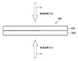
- this indirect conversion type radiation detection unit 106 As shown in FIG. 19, radiation is irradiated from the side on which the scintillator 404 is formed, and a radiation image is formed by the TFT substrate 450 provided on the back surface side of the radiation incident surface.
- the so-called back side reading method so-called PSS (Penetration Side Sampling) method
- PSS Pulsion Side Sampling
- the radiation detection unit 106 of the indirect conversion system is a so-called surface reading system (so-called ISS (so-called ISS), in which radiation is irradiated from the TFT substrate 450 side, and a radiation image is read by the TFT substrate 450 provided on the surface side
- ISS surface reading system
- the Irradiation Side Sampling method is used, radiation transmitted through the TFT substrate 450 enters the scintillator 404, and the TFT substrate 450 side of the scintillator 404 emits light more strongly.
- the radiation detection unit 106 has a resolution of a radiation image obtained by imaging because the light emission position of the scintillator 404 with respect to the TFT substrate 450 is closer to the front side reading method than to the back side reading method. high.
- the radiation detection unit 106 hardly absorbs the radiation, and the radiation is transmitted through the TFT substrate 450 by the surface reading method. Less radiation absorption. Therefore, the decrease in sensitivity to the radiation X can be suppressed.
- the photoelectric conversion film 414 of the TFT substrate 450 is made of an organic photoelectric conversion material, the absorption of radiation by the photoelectric conversion film 414 is hardly present and attenuation of the radiation can be suppressed to a low level. ing.
- the substrate 400 can be formed of a plastic resin, aramid, or bio-nanofiber, which absorbs less radiation. Since the substrate 400 formed in this manner has a small amount of absorption of radiation, the decrease in sensitivity to the radiation X can be suppressed even when the radiation passes through the TFT substrate 450 by the surface reading method.
- the photoelectric conversion film 414 of the indirect conversion type radiation detection unit 106 is made of an organic photoelectric conversion material
- the active layer 424 of the TFT 170 is made of an amorphous oxide
- the substrate 400 is formed of a flexible substrate such as plastic resin, aramid, bio-nanofiber, or the like which has low absorption of radiation.
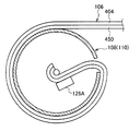
- the radiation detection unit 106 is wound around the winding units 108 and 110 so that the TFT substrate 450 is inside the radiation detection unit 106.
- the casing 102 and the casing 104 are separated and the radiation detection unit 106 is pulled out during imaging, and the patient 210 is disposed on the pulled out radiation detection unit 106.
- the irradiation unit 212 emits radiation.
- imaging is performed by the surface reading method.
- the scintillator 404 may be formed of a columnar crystal of CsI: Tl.
- the columnar crystals of CsI: Tl are hard and fragile, and therefore, the scintillator 404 can not be wound around the winding units 108 and 110 as it is. Therefore, for example, as shown in FIG. 21, a non-columnar crystal region 404A is formed as a scintillator 404 on a TFT substrate 450, and a columnar crystal region 404B is formed thereon. Then, for example, as shown in FIGS.
- the cuts 452 are formed by cutting the columnar crystal region 404B of the scintillator 404 in parallel at a predetermined depth and a predetermined distance that the columnar crystals in the columnar crystal region 404B do not break.
- the surface on the columnar crystal region 404B side of the scintillator 404 is sealed with a protective sheet 454 having elasticity.
- the radiation detection unit 106 in which such a scintillator 404 is formed is wound on the winding units 108 and 110 so that the TFT substrate 450 is inside the radiation detection unit 106 as shown in FIG.
- the CsI: Tl columnar crystals of the columnar crystal region 404B are prevented from coming apart, and it is possible to suppress the loss of an image at the incision 452 when photographing.
- the provision of the cut 452 in the columnar crystal region 404B of the scintillator 404 allows the radiation detection unit 106 to be wound around the winding units 108 and 110.
- the radiation detection unit 106 is taken up by the take-up unit 108 as shown in FIG.
- the heat from the electronic circuit 126A housed in the portion 120 can be recovered quickly.
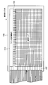
- the electronic circuit 126A in which the line scan drive unit 174 and the readout circuit 130 are incorporated is provided at the end of the radiation detection unit 106 in the longitudinal direction.
- the respective gate lines 158 are connected to the electronic circuit 126A through the first flexible wiring portion 160, and the signal lines 162 of the radiation detection portion 106 are connected to the electronic circuit 126A through the second flexible wiring portion 164.
- drive circuits such as the line scan drive unit 174 and the read circuit 130 are configured by a hard silicon driver IC.
- the active layer 424 of the TFT 170 is formed of, for example, amorphous silicon, amorphous oxide, organic semiconductor material, carbon nanotube or the like, the switch element such as the TFT 170 can be flexibly formed on the substrate. .
- a line scan drive unit 174 is formed on one end side in the width direction of the radiation detection unit 106 using, for example, a switch element such as an organic TFT to drive each gate line 158. It is also good. Thereby, even when drive circuits such as the line scanning drive unit 174 and the readout circuit 130 are formed in the radiation detection unit 106, the flexibility of the radiation detection unit 106 can be maintained.
- the radiation detection unit 106 is accommodated in the housing 102 and the housing 104 by winding the radiation detection unit 106 around the winding unit 108 and the winding unit 110, but the radiation detection unit 106 is
- the housing 102 and the housing 104 may be freely accommodated and retracted from the housing 102 and the housing 104.
- the radiation detection unit 106 may be accommodated in the housing 102 or the housing 104 by folding it.
- a drive mechanism for housing the radiation detection unit 106 and a drive mechanism for folding the radiation detection unit 106 may be provided in the housing 102 or the housing 104.
- the mechanism for containing may be a bellows structure or the like.
- the motor is provided in both the housing 102 and the housing 104 in this embodiment, the motor may be omitted.
- the user manually turns off the stopper and manually pulls out the radiation detection unit 106 from the housing 102 or the housing 104 while grasping the exposed area by looking at the display unit 142.
- the housing 102 and the housing 104 be configured to sound an alarm or automatically turn on the stopper when the exposed area reaches the area designated by the input unit 136.
- the motor is not provided in the housing 102 and the housing 104, it is desirable that the automatic winding and drawing mechanism of the radiation detection unit 106 described in the first embodiment can be added.
- the cost can be reduced because there is no automatic winding and drawing out mechanism, and when the user wants to provide automatic winding and drawing out after purchasing the electronic cassette, the automatic winding and drawing out mechanism is newly added. It can respond by expanding.
- a motor it is desirable to provide a winding unit drive lever capable of manually winding the radiation detection unit 106.
- the cost can be reduced by the amount of the motor, and the power consumption is also reduced.
- only one motor may be provided in either the housing 102 or the housing 104. Even if there is only one motor, the electronic cassette can automatically perform the control other than the control of housing the radiation detection unit 106 in the case where the motor is not provided. For example, when a certain area is used for imaging and it is desired to change the exposure position for the next imaging, the electronic cassette winds up the radiation detection unit 106 by the same area as the previously used area in a housing provided with a motor. Thus, the exposure position of the radiation detection unit 106 can be changed.
- the electronic cassette can be made to have a larger exposed area than the area of the previously used area by slightly pulling it out after taking up more than the area used in the previous time.
- the electronic cassette can be realized by winding up the radiation detection unit 106 more than the area of the previously used area.
- the electronic cassette can automatically change the exposure area and the exposure position.
- the user manually moves the winding unit drive lever to wind up or pull out the radiation detection unit 106 to adjust the exposed area I do.
- the electronic cassette When the motor is provided only inside one of the housings in this manner, the electronic cassette has an exposed area and a photographing area when the electronic cassette shoots in a direction in which winding is performed in the housing where the motor is provided. Position control can be performed automatically. In addition, the electronic cassette 100 can automatically put the radiation detection unit 106 in the accommodation state. In the case where the motor is provided only in one of the housings, it is desirable that a mechanism capable of generating power by turning the take-up unit driving lever is provided in the housing without the motor and the battery can be charged by turning the lever.
- the electronic cassette automatically adjusts the exposure area and the exposure position in shooting in the direction that can be automatically adjusted by the motor, and in shooting in the direction that can not be adjusted by the motor automatically, the user can
- the take-up unit drive lever is rotated to adjust the exposure area and the exposure position, and at the same time, the electronic cassette can charge the battery.
- the battery 146 is provided only in the housing 102 in this embodiment, a removable battery may be provided in both the housing 102 and the housing 104.
- a removable battery may be provided in both the housing 102 and the housing 104.
- hot swap can be performed, in which a new battery is replaced without turning off the power, even when one of the battery capacities is lost.
- batteries are provided in both the housing 102 and the housing 104, the difference in mass between the housing 102 and the housing 104 is reduced, and the weight balance of the entire electronic cassette 100 is improved.
- stoppers are provided on both the housing 102 and the housing 104 in this embodiment, the stoppers may be provided on only one of them. In this case, only one stopper controls whether or not the radiation detection unit 106 is wound and pulled out.
- the cassette control unit 128 stores the exposure area and the exposure position of the radiation detection unit 106 in the use status storage unit 139 for each imaging.
- any method may be used as long as the use state of each area of the radiation detection unit 106 and the area used immediately before can be grasped.
- the storage of the exposed area and the exposed position does not necessarily have to be performed automatically by the device. For example, the user may look at the exposed area and the exposed position displayed on the display unit 142, make a note, and input the result to the electronic cassette 100 later. Also, it does not have to be done for each use.
- the electronic cassette 100 can grasp the exposed area and the exposed position of the radiation detection unit 106, the exposed area or the exposed position of the radiation detection unit 106 is obtained from the radiographic image information obtained by imaging. Information to be specified may be linked as metadata and stored in the image storage unit 137. In this way, when the user looks at the captured image and finds a problem with the radiation detection unit 106, it is possible to identify in which region of the radiation detection unit 106 the problem has occurred. In this case, it is desirable for the user to be able to input to the electronic cassette 100 a region where a problem occurs in the radiation detection unit 106 as a region where degradation due to radiation has occurred (hereinafter referred to as a degraded region).
- a degraded region a region where a problem occurs in the radiation detection unit 106 as a region where degradation due to radiation has occurred
- the electronic cassette 100 that has received the input of the deteriorated area from the user and specified the deteriorated area to control the exposure position of the radiation detection unit so that the deteriorated area is not used. This control prevents the area in which the occurrence of deterioration has been confirmed from being used again, and can prevent the occurrence of a problem in the image quality. Further, it is desirable that the electronic cassette 100 that has received the input of the deteriorated area from the user displays the area where the deterioration has occurred on the display unit 142. For example, in 208A of FIG. 6, the display unit 142 performs display such as painting out the area where deterioration has occurred. Such display allows the user to grasp the degraded area of the radiation detection unit 106 at a glance.
- the electronic cassette 100 it is desirable for the electronic cassette 100 to cause the display unit 142 to display a message prompting the user to repair as the deteriorated area increases.
- the electronic cassette 100 emphasizes the display to be repaired every time the deterioration area increases and displays the display on the display unit 142.
- the identification of the degraded area may be automatically performed by the electronic cassette 100 and stored in the use status storage unit 139 or the like.
- the degraded area can be calculated, for example, from how fixed pattern noise occurs.
- the electronic cassette 100 performs correction using, for example, peripheral pixel values without using the abnormal value.
- the electronic cassette 100 reads out the pixel value at an arbitrary time when imaging is not performed such as a standby time to detect a pixel having an abnormal value, and a pixel having an abnormal value is deteriorated. You may judge that. Even when the degraded area is automatically identified in this manner, it is desirable that the electronic cassette 100 render the degraded area unusable.
- the electronic cassette 100 may associate the radiation image information with an ID or the like for specifying the electronic cassette 100 or the radiation detection unit 106 as metadata. In this way, when there are multiple electronic cassettes, it can be specified which electronic cassette has a problem.
- the winding amount detection sensors 140A and 140B calculate the rotation angle of the winding unit 108 or the winding unit 110 based on the length of the radius of the winding unit 108 or the winding unit 110.
- the position of the case 102 and the case 104 with respect to the radiation detection unit 106 is specified by obtaining the area in which the radiation detection unit 106 is taken up in the case 102 and the case 104.
- the winding amount detection sensor may read the scale of the radiation detection unit 106 and determine the position of the housing 102 or the radiation detection unit 106 of the housing 104.
- the winding amount detection sensor does not necessarily have to be provided in the housing.
- the standard for adjusting the exposure area and the exposure position of the radiation detection unit 106 is the housing for the radiation detection unit 106. Position of the body 102 and the housing 104. If the cassette control unit 128 specifies which position on the radiation detection unit 106 the housing 102 and the housing 104 should be moved to next, the exposure area and the exposure position of the radiation detection unit 106 are adjusted. it can. With such a configuration, the housing 102 and the housing 104 can adjust the exposure area and the exposure position only by grasping the one-dimensional position on the radiation detection unit 106.
- the whole area of the radiation detection unit 106 may be read out, and an area in which data having a value not considered as noise can be read out may be specified as the used area.
- a bar code or the like may be provided to the radiation detection unit 106, and the amount of winding may be determined by reading the bar code.
- the winding amount detection sensor grasps the position on the radiation detection unit of one casing. Then, the electronic cassette 100 brings the casing 102 and the casing 104 close to each other, sets the exposed area of the radiation detection unit 106 to zero, and then withdraws the radiation detection unit 106. By this, the exposed area can be adjusted by the change of the value of one winding amount detection sensor.
- the cassette control unit 128 adds the thickness of the radiation detection unit 106 to the radius of the winding unit 108 or the winding unit 110 depending on how many layers of the radiation detection unit 106 are wound. good. With this configuration, the exposed area of the radiation detection unit 106 can be adjusted more accurately.
- the radiation detection unit 106 is accommodated in the housing 102 or the housing 104 by using the winding button 196 or the winding button 198 at the end of imaging.
- the cassette control unit 128 is automatically wound on the housing 102 or the housing 104 until the radiation detection unit 106 is accommodated. Control may be performed.
- a detachable cooling member inside the winding unit 108 or the winding unit 110.
- a cooling member inside the winding unit 108 or the winding unit 110, heat transfer from the radiation detection unit 106 wound up to the winding unit 108 or the winding unit 110 or heat generation from the radiation detection unit 106 Can be prevented. If the radiation detection unit 106 is photographed while having a temperature higher than the normal temperature, the amount of noise on the radiation image increases. Particularly in the state where the radiation detection unit 106 is wound in multiple layers as in the present embodiment, the heat is transmitted over the wide range of the radiation detection unit 106, so the winding unit 108 or the winding unit It is effective to provide a cooling member inside 110.
- the cooling member for example, a cylindrical member concentric with the rotation shaft 112 can be considered.
- an acceleration sensor and an alarm in the housing 102 or the housing 104.
- the casing 102 or the casing 104 is moved while the radiation detection unit 106 is being wound up or pulled out, the radiation detection unit 106 is wound in the wrong direction, and the radiation detection unit 106 is broken. There is a case. Therefore, an acceleration sensor is provided in the housing 102 or the housing 104.
- the cassette control unit 128 detects the housing 102 or the housing 104 based on the detection result of the acceleration sensor.
- the cassette control unit 128 When it is detected that the radiation detection unit 106 has been moved in a direction different from the winding or drawing-out direction, it is desirable that the user rings by an alarm to notify the user. In that case, it is more desirable for the cassette control unit 128 to simultaneously stop winding and drawing of the radiation detection unit 106. When the cassette control unit 128 stops the winding and drawing of the radiation detection unit 106, the radiation detection unit 106 can be prevented from being wound in the wrong direction.
- the input unit 136 and the display unit 142 are provided on the housing 102, but the input unit 136 and the display unit 142 may be provided on the housing 104. Alternatively, the input unit 136 may be a remote controller that is separated from the housing.
- the imaging area storage unit 138 may be an external memory that is removable.
- the imaging area storage unit 138 is an external memory, the value of the exposure area corresponding to the imaging region stored in the imaging area storage unit 138 can be replaced with one having another value.
- the imaging area storage unit 138 is replaced for each patient.
- the image storage unit 137 may be a removable external memory. Assuming that the image storage unit 137 is an external memory, for example, by replacing the memory for each imaging, it is not confused with a radiographic image obtained by imaging another person.
- the housing 102 or the housing 104 may be provided with a handle.
- the handle By providing the handle, the user can carry the electronic cassette 100 by holding the handle when the radiation detection unit 106 is in the storage state.
- the power of the electronic cassette 100 is turned on by turning on the power with the power button 187, but the method of turning on the power is not limited to this.
- control may be considered in which the power is turned on when the user pulls the housing 102 or the housing 104 and exposes the radiation detection unit to the outside.
- control may be considered in which the user manually winds up the radiation detection unit 106 and automatically turns off the power when the radiation detection unit 106 is accommodated.
- the winding amount detection sensor is always energized, the power is turned on when the exposed area is not zero, and the power is turned off when the exposed area is zero.
- an acceleration sensor is provided in the winding unit 108 or the winding unit 110, and based on the detection result of the acceleration sensor, the rotation of the winding unit 108 or the winding unit 110 is detected to turn on the power. Control etc. can be considered.
- the battery can be charged if an interface is provided so that the power outlet can be detachably connected and the power outlet is connected to the power source. If a power outlet is used, the power from the power source may drive the electronic cassette 100.
- the power can not be turned on or the housing 102 and the housing 104 can not be separated.
- the power can not be turned on when the battery 146 is not sufficiently charged and the power is not sufficient during use, or the temperature of the radiation detection unit 106 is higher than the allowable range, or Control is performed such that the housing 102 and the housing 104 can not be separated.
- a known structure can be used as a structure in which the housing 102 and the housing 104 can not be separated.
- a stopper that maintains the contact between the housing 102 and the housing 104 can be provided, and the stopper can be electrically controlled.
- a mechanism for winding and drawing the radiation detection unit 106 may be separately provided near the opening 116 and the opening 118.
- the radiation detection unit 106 may slacken in the housing 102 or the housing 104.
- the radiation detection unit 106 can be used as the radiation detection unit 106 without slack in the housing 102 or the housing 104. It can be exposed to the outside.
- the shape of the radiation detection unit 106 is not limited to a rectangle as long as the radiation detection unit 106 has such an area that radiation imaging can be performed a plurality of times.
- the radiation detection unit 106 may have any shape as long as the rotation shaft 112 and the rotation shaft 114 can be connected and can be accommodated in the housing 102 and the housing 104.
- the length of the radiation detection unit 106 in the direction perpendicular to the winding direction of the radiation detection unit 106 can be changed according to the winding of the winding unit.
- the shape of the radiation detection unit 106 is not limited to a neat shape such as a rectangle or a trapezoid, and may be a more complicated shape, for example, a shape according to the patient's body.
- the display unit 142 can display the shape of the radiation detection unit 106 based on the stored shape of the radiation detection unit 106.
- the user can select a desired imaging region based on the display of the shape of the radiation detection unit 106 by the display unit 142. According to this configuration, the user can easily find and use a desired shape, even using the radiation detection unit 106 having a more complicated shape.
- the radiation detection unit 106 be detachable from the rotation shaft 112 or the rotation shaft 114. If the radiation detection unit 106 is detachable, it is possible to remove the radiation detection unit 106 from the rotation shaft, for example, when the radiation detection unit 106 is desired to be under the patient 210 sleeping as shown in FIG. Become. It is possible to make only the radiation detector on the removed side under the patient 210 and then connect the housing. Thus, imaging can be performed without putting a burden on the sleeping patient 210 to float the body more than necessary. In addition, if the radiation detection unit 106 is detachable from both the rotation shaft 112 and the rotation shaft 114, the radiation detection unit 106 can be replaced when the radiation detection unit 106 is entirely deteriorated.
- portions other than the radiation detection unit 106 of the electronic cassette 100 can be reused, and even if the radiation detection unit 106 is entirely degraded, it is not necessary to newly purchase the entire electronic cassette 100. .
- the radiation detection unit 106 can be replaced by replacement.
- an electronic cassette having radiation detectors of various shapes may be configured by additionally purchasing the radiation detectors 106 having different shapes and replacing the radiation detectors 106 according to the purpose of use. it can.
- the electronic cassette 100 automatically read the information of the newly connected radiation detection unit 106.
- it is conceivable to embed an IC tag in the radiation detection unit 106 communicate with the electronic cassette 100, and read the usage state of the radiation detection unit 106 newly connected and the shape of the radiation detection unit 106.
- the housing 102 and the housing 104 automatically approach each other in the operation of housing the radiation detection unit 106. This eliminates the need for the user to hold the case by himself and place the radiation detection unit 106 in the accommodated state.
- FIG. 12 is an external perspective view of the electronic cassette 300 according to the present embodiment.
- the electronic cassette 300 has an expandable support rod 308 and a support rod 310 parallel to the winding and extracting direction of the radiation detection unit 306 at the upper and lower portions of the radiation detection unit 306, and the housing 302
- This embodiment differs from the first embodiment in that a handle 312A is provided on the outer surface and a handle 312B is provided on the outer surface of the housing 304.
- FIG. 13 is an external perspective view of the electronic cassette 300 according to the present embodiment in a state in which the radiation detection unit 306 is accommodated.
- the housing 302 and the housing 304 are in close contact, and the handle 312A and the handle 312B are in close contact to configure one handle 314.
- the handle 314 facilitates transport of the electronic cassette 300 when the electronic cassette 300 is in the storage state.
- FIG. 14 is an external perspective view of the electronic cassette 300. Descriptions of parts similar to those in the first embodiment are omitted.
- the motor in the housing 302 extends and retracts the support rod 308 and the support rod 310 in addition to the winding unit. Specifically, in response to the change in the exposed area, the motor telescopically drives the support rods 308 and 310 to adjust the lengths of the support rods 308 and 310. More specifically, the support rod 308 and the support rod 310 extend until the radiation detection unit 306 is in a stretched state.
- the winding unit 316 or the winding unit 318 is rotated by the motor, but when only one winding unit is wound to perform the extraction operation, the radiation detection unit 306 Is in a slack state.
- extension of the support rods 308 and the support rods 310 stretches the radiation detection unit 306 without slack.
- the expansion / contraction stopper acts on the support member 308 or the support member 310 so that the expansion / contraction can not be performed. The stopper is turned off in accordance with the change in the exposure position of the radiation detection unit 306.
- the support rod 308 or the support rod 310 expands and contracts in accordance with the change in the exposed area of the radiation detection unit 306, thereby enhancing the stability of the electronic cassette 300 when the housing 302 and the housing 304 are separated.
- the control of the other parts is the same as that of the first embodiment, and therefore, is omitted.
- FIG. 15A is a schematic view of the support bar 310.
- the specific structure of the support rod 310 will be described using FIG. 15A.
- the support rods 310 are formed by connecting a plurality of cylindrical members having different radii and having a top surface radius smaller than the bottom surface radius in multiple stages.
- the cylindrical member 310A has the largest radius and the outermost side, and the cylindrical member 310B has a slightly smaller radius than the cylindrical member 310A, and is stacked inside the cylindrical member 310A.
- the cylindrical member 310C has a smaller radius than the cylindrical member 310B, and is stacked inside the cylindrical member 310B.
- the support rod 310 is configured by sequentially overlapping inward the cylindrical members having a slightly smaller radius as described above.
- the support rod 310 has a length corresponding to one cylindrical member as shown in FIG. 15B when it is shortened, and when it is extended, it has a length that is a constant multiple of the cylindrical member.
- the support bar 308 also has the same configuration as the support bar 310. It is desirable that the support rods 308 and the support rods 310 have such rigidity that they do not bend even in an extended state.
- the cylindrical member is driven by the motor 320 to expand and contract.
- the telescopic drive by a motor can use a known structure. For example, as shown in FIG. 16, a structure may be used in which the rotational drive of the motor 320 is converted to the vertical movement of the rod 324 via the gear 322.
- the rod 324 is accommodated inside the support rod 308 or the support rod 310, and by connecting with the support rod 308 or the support rod 310, the up and down movement of the rod 324 can expand and contract the support rod 308 or the support rod 310.
- the support rods 308 and 310 expand and contract according to the change of the exposed area of the radiation detection unit 306, so that the radiation detection unit 306 is not loosened and photographed. It can be performed. Further, by providing the support rod 308 or the support rod 310, it is possible to eliminate the unstable state in which the housing 302 and the housing 304 are connected only by the radiation detection unit 306, and the rigidity of the entire apparatus is improved. Do. In particular, when the support rod 308 or the support rod 310 is rigid, it is possible to prevent the radiation detection unit 306 from being twisted and damaged when either the housing 302 or the housing 304 falls.
- the area of the radiation detection unit 306 may be used next by turning off only the stoppers in the casing from which the radiation detection unit 306 is pulled out and extending the support rods 308 and the support rods 310.
- the unused area may be wound by a motor or wound manually. As a result, it is possible to reduce the power consumption of the motor when the radiation detection unit 306 is pulled out.
- the support rods 308 and the support rods 310 are hollow, cables and the like can be passed therethrough.
- the power supply line exiting from the battery is passed through the support rod 308 or the support rod 310. Is considered. According to this configuration, since the battery supply line does not pass through the radiation detection unit 306, noise can be reduced without affecting each pixel of the radiation detection unit 306.
- a support rod is not restricted to what was demonstrated here, What is necessary is just a structure which can be expanded-contracted.
- a bellows structure can be used.
- the exposure area and the exposure position of the radiation detection unit can be made variable.
- the electronic cassette is provided with an automatic drive mechanism that automatically takes up and withdraws the radiation detection unit from the housing, stores the usage status of the radiation detection unit, and Control is performed to expose an area different from the area.
- an automatic drive mechanism that automatically takes up and withdraws the radiation detection unit from the housing, stores the usage status of the radiation detection unit, and Control is performed to expose an area different from the area.
- the electronic cassette stores the use state of each region of the radiation detection unit, and performs imaging using the least used region of the radiation detection unit. By this, it is possible to average the use condition of the radiation detection unit, and to average the deterioration degree of the radiation detection unit.
- the present invention can be used in a radiation imaging apparatus.
Landscapes
- Health & Medical Sciences (AREA)
- Life Sciences & Earth Sciences (AREA)
- Medical Informatics (AREA)
- Engineering & Computer Science (AREA)
- Physics & Mathematics (AREA)
- Radiology & Medical Imaging (AREA)
- Surgery (AREA)
- Nuclear Medicine, Radiotherapy & Molecular Imaging (AREA)
- Optics & Photonics (AREA)
- Pathology (AREA)
- Biophysics (AREA)
- Biomedical Technology (AREA)
- Heart & Thoracic Surgery (AREA)
- Molecular Biology (AREA)
- High Energy & Nuclear Physics (AREA)
- Animal Behavior & Ethology (AREA)
- General Health & Medical Sciences (AREA)
- Public Health (AREA)
- Veterinary Medicine (AREA)
- Mathematical Physics (AREA)
- Apparatus For Radiation Diagnosis (AREA)
- Measurement Of Radiation (AREA)
- Radiography Using Non-Light Waves (AREA)
Abstract
Description
図1は、本実施の形態に係る電子カセッテ100の外観斜視図である。図1を用いて電子カセッテ100の概略構成について説明する。図1の斜線は筐体の断面を表す。電子カセッテ100は、外形がほぼ直方体状の形状を有する筐体102および筐体104と、筐体102または筐体104内に収容され、被写体を透過した放射線源からの放射線を検出し、放射線画像情報に変換する可撓性の放射線検出部106とを有する。放射線検出部106は、撮影位置を変えて複数回の撮影ができるような十分な長さを持った矩形のシート状に形成されている。放射線検出部106は、具体的には、長辺が約5メートル、短辺が約1メートルである。
図12は、本実施の形態に係る電子カセッテ300の外観斜視図である。電子カセッテ300の外観は、放射線検出部306の上部および下部に、放射線検出部306の巻取り引き出し方向と平行で、伸縮自在な支持棒308および支持棒310を設けた点と、筐体302の外面に取っ手312A、筐体304の外面に取っ手312Bを設けた点とが実施の形態1と異なる。
Claims (28)
- 可撓性を有する放射線検出部と、
第1の筐体と、
第2の筐体と、
前記放射線検出部を、前記第1の筐体内に収容し、または前記第1の筐体内から引出す第1の駆動機構と、
前記放射線検出部を、前記第2の筐体内に収容し、または前記第2の筐体内から引出す第2の駆動機構と、を有し、
前記第1の駆動機構に前記放射線検出部の一端部が取り付けられ、
前記第2の駆動機構に前記放射線検出部の他端部が取り付けられた、
放射線撮像装置。 - 前記第1の筐体または前記第2の筐体の少なくとも一方に、
前記第1の駆動機構または前記第2の駆動機構を自動で駆動させる自動駆動機構と、
該自動駆動機構を制御する制御部と、
を設けた請求項1の放射線撮像装置。 - 前記放射線検出部に対する前記第1の筐体の位置および/または第2の筐体の位置を検出する位置検出部をさらに有する
請求項2の放射線撮像装置。 - 前記第1の筐体または前記第2の筐体の少なくとも一方に、前記放射線検出部の使用状況を記憶する記憶部をさらに有し、
前記制御部は、
前記位置検出部の検出結果に基づいて、撮影に使用した前記放射線検出部の領域を特定し、
特定した前記放射線検出部の領域を、前記放射線検出部の使用状況として前記記憶部に記憶するように制御する
請求項2の放射線撮像装置。 - 前記制御部は、
撮影に使用した前記放射線検出部の領域を撮影毎に前記記憶部へ記憶させることで前記放射線検出部の使用状況を記憶し、
直前の撮影で使用した前記放射線検出部の領域と異なる領域が外部へ露出するように前記自動駆動機構を制御する請求項4の放射線撮像装置。 - 前記制御部は、前記記憶部に記憶した前記放射線検出部の使用状況に基づいて、前記放射線検出部の領域毎の使用状況が略等しくなるように前記自動駆動機構を制御する請求項5の放射線撮像装置。
- 前記制御部は、
撮影毎に、前記第1の筐体または前記第2の筐体のどちらか一方から前記放射線検出部を引き出して、前記放射線検出部の領域を使用するように前記自動駆動機構を制御し、
前記方向に引き出して使用する前記放射線検出部の領域が不足する場合は、
前記放射線検出部の端部から前記方向と逆の方向における前記放射線検出部の領域を使用するように前記自動駆動機構を制御する請求項6の放射線撮像装置。 - 前記制御部は、
前記記憶部に記憶した前記放射線検出部の使用回数が、予め定められた回数を超えると、前記放射線検出部の露出する領域を変更可能とする請求項7の放射線撮像装置。 - 前記放射線検出部の累積放射線量を検出する累積放射線検出機能をさらに有し、
前記累積放射線量検出機能で検出された累積放射線量が、予め設定された閾値を超えると、前記制御部は前記放射線検出部の露出領域を変更可能とする請求項8の放射線撮像装置。 - 前記制御部は、
前記放射線検出部を所定の間隔で分割した領域毎の使用状況を前記記憶部に記憶するように制御する請求項5の放射線撮像装置。 - 前記制御部は、
前記記憶部に記憶した、前記放射線検出部の所定の間隔毎に分割した領域毎の使用状況に基づいて、前記放射線検出部の使用状況が最も少ない領域が外部に露出するように前記自動駆動機構を制御する請求項10の放射線撮像装置。 - 前記第1の筐体または前記第2の筐体の少なくとも一方に設けられた入力部をさらに有し、
前記記憶部は、複数種類の撮影面積を記憶し、
前記入力部は、前記記憶部に記憶されている複数種類の撮影面積のうちのいずれか1つの撮影面積を設定する
請求項5乃至11のいずれか1項記載の放射線撮像装置。 - 前記制御部は、前記位置検出部の検出結果に基づいて、外部へ露出している前記放射線検出部の領域の面積を特定し、
前記入力部によって設定された撮影面積と、外部へ露出している前記放射線検出部の領域の面積とが、略同一となるように前記自動駆動機構を制御する請求項12の放射線撮像装置。 - 前記位置検出部は、前記第1の筐体内へ収容されている前記放射線検出部の領域の面積と、前記第2の筐体内へ収容されている前記放射線検出部の領域の面積と、前記放射線検出部の領域全体の面積とに基づいて、前記放射線検出部に対する前記第1の筐体または前記第2の筐体の位置を検出することを特徴とする請求項3乃至13のいずれか1項記載の放射線撮像装置。
- 前記制御部は、
放射線撮像によって得られた放射線画像情報に、前記位置検出部の検出結果に基づいて特定した、放射線撮像に使用した前記放射線検出部の領域を関連付けて、前記放射線画像情報を前記記憶部に保存する
請求項4乃至14のいずれか1項記載の放射線撮像装置。 - 前記第1の駆動機構は、前記第1の筐体内に回転自在に設けられた第1の巻取部であり、
前記第2の駆動機構は、前記第2の筐体内に回転自在に設けられた第2の巻取部である、請求項1乃至15のいずれか1項記載の放射線撮像装置。 - 前記第1の巻取部または前記第2の巻取部が前記放射線検出部を巻き取る方向に回転する巻取操作によって、前記放射線検出部が前記第1の筐体または前記第2の筐体内に巻回されて収容され、
前記第1の巻取軸または前記第2の巻取軸に巻き取られた前記放射線検出部を、前記第1の筐体または前記第2の筐体内から引き出す方向へ引く引出操作によって、前記放射線検出部が前記第1の筐体または前記第2の筐体から引き出される
請求項16の放射線撮像装置。 - 前記第1の筐体または前記第2の筐体の少なくとも一方に、表示部を設けた請求項1乃至17のいずれか1項記載の放射線撮像装置。
- 前記第1の筐体または前記第2の筐体の少なくとも一方に、前記放射線検出部の巻取りおよび引出しの可否を制御するストッパが設けられた請求項1乃至18のいずれか1項記載の放射線撮像装置。
- 前記第1の駆動機構または前記第2の駆動機構の少なくとも一方が中空構造を持ち、前記中空構造に前記制御部が収容されている請求項2乃至19のいずれか1項記載の放射線撮像装置。
- 前記中空構造に着脱可能な冷却部材を有する請求項1乃至20のいずれか1項記載の放射線撮像装置。
- 前記第1の筐体は第1の保持部をさらに有し、
前記第2の筐体は第2の保持部をさらに有し、
前記第1の筐体および前記第2の筐体が重なった場合、
前記第1の保持部および前記第2の保持部が重なり、1つの保持部を形成する請求項1乃至21のいずれか1項記載の放射線撮像装置。 - 前記第1の筐体または前記第2の筐体は、加速度センサをさらに有し、
前記位置検出部によって、前記第1の筐体または第2の筐体の、前記放射線検出部の収容方向の位置の変化または引出し方向の位置の変化が検出されている状態で、
前記加速度センサの検出結果に基づいて、前記第1の筐体または前記第2の筐体が、前記放射線検出部の収容方向または巻取り方向と異なる方向に移動したことを検出すると、警告を行う警告部をさらに有する
請求項3乃至22のいずれか1項記載の放射線撮像装置。 - 前記第1の筐体または前記第2の筐体の少なくとも一方に、バッテリが着脱自在である請求項2乃至23のいずれか1項記載の放射線撮像装置。
- 前記放射線検出部は、放射線が照射されることにより発光する蛍光体の柱状結晶を含んで構成されたシンチレータ、及び当該シンチレータで発生した光を電気信号に変換して電荷を蓄積する固体検出素子を積層させて形成された
請求項1乃至24のいずれか1項記載の放射線撮像装置。 - 前記蛍光体を、CsIとした
請求項25項記載の放射線撮像装置。 - 前記放射線検出部は、前記固体検出素子側が内側となるように巻き取られて収容され、
前記シンチレータに、巻き取り方向に対して垂直方向に所定の間隔で切目が設けられた
請求項25又は請求項26項記載の放射線撮像装置。 - 前記固体検出素子は、有機光電変換材料を用いて形成され、
前記放射線検出部に、非晶質酸化物、有機半導体材料、カーボンナノチューブの何れかにより活性層が形成され、前記固体検出素子から電荷を読み出す薄膜トランジスタが形成された
請求項25~請求項27の何れか1項項記載の放射線撮像装置。
Priority Applications (2)
| Application Number | Priority Date | Filing Date | Title |
|---|---|---|---|
| CN201180016192.XA CN102821692B (zh) | 2010-03-31 | 2011-03-24 | 放射线摄像装置 |
| US13/636,698 US8939640B2 (en) | 2010-03-31 | 2011-03-24 | Radiographic imaging device |
Applications Claiming Priority (4)
| Application Number | Priority Date | Filing Date | Title |
|---|---|---|---|
| JP2010-084581 | 2010-03-31 | ||
| JP2010084581 | 2010-03-31 | ||
| JP2010258225A JP5666259B2 (ja) | 2010-03-31 | 2010-11-18 | 放射線撮像装置 |
| JP2010-258225 | 2010-11-18 |
Publications (1)
| Publication Number | Publication Date |
|---|---|
| WO2011125528A1 true WO2011125528A1 (ja) | 2011-10-13 |
Family
ID=44762482
Family Applications (1)
| Application Number | Title | Priority Date | Filing Date |
|---|---|---|---|
| PCT/JP2011/057259 Ceased WO2011125528A1 (ja) | 2010-03-31 | 2011-03-24 | 放射線撮像装置 |
Country Status (4)
| Country | Link |
|---|---|
| US (1) | US8939640B2 (ja) |
| JP (1) | JP5666259B2 (ja) |
| CN (1) | CN102821692B (ja) |
| WO (1) | WO2011125528A1 (ja) |
Families Citing this family (10)
| Publication number | Priority date | Publication date | Assignee | Title |
|---|---|---|---|---|
| JP5577862B2 (ja) * | 2010-06-07 | 2014-08-27 | トヨタ自動車株式会社 | 放射線撮像方法および放射線撮像システム |
| JP5995482B2 (ja) * | 2012-03-29 | 2016-09-21 | キヤノン株式会社 | 放射線画像撮影装置及びそのシステム |
| JP6137794B2 (ja) * | 2012-08-06 | 2017-05-31 | キヤノン株式会社 | 放射線撮影装置、その制御方法およびプログラム |
| ITVI20130216A1 (it) * | 2013-08-26 | 2015-02-27 | Next Sight Srl | Apparato e metodo di acquisizione di dati medici |
| CN104780609B (zh) * | 2014-01-15 | 2020-10-02 | 索尼公司 | 终端到终端资源分配方法、用户设备、基站和通信系统 |
| JP6611449B2 (ja) * | 2015-03-31 | 2019-11-27 | キヤノン株式会社 | 放射線撮像システム及び放射線撮影システム |
| JP6735215B2 (ja) * | 2016-11-21 | 2020-08-05 | 株式会社東芝 | 放射線検出器 |
| US10302782B1 (en) * | 2017-11-15 | 2019-05-28 | Varex Imaging Corporation | Flexible detector for x-ray imaging |
| JP2023127002A (ja) * | 2020-08-06 | 2023-09-13 | パナソニックIpマネジメント株式会社 | 電離放射線変換デバイスおよび電離放射線の検出方法 |
| WO2026006285A1 (en) * | 2024-06-28 | 2026-01-02 | Baker Hughes Holdings Llc | Mounting a non-destructive testing device |
Citations (5)
| Publication number | Priority date | Publication date | Assignee | Title |
|---|---|---|---|---|
| JPS6252537A (ja) * | 1985-09-02 | 1987-03-07 | Minolta Camera Co Ltd | ロ−ルフイルムの終端検出方法 |
| JPH01140139A (ja) * | 1987-11-27 | 1989-06-01 | Hitachi Medical Corp | X線間接撮影装置 |
| JP2009130209A (ja) * | 2007-11-26 | 2009-06-11 | Fujifilm Corp | 放射線撮像素子 |
| JP2009205155A (ja) * | 2008-01-31 | 2009-09-10 | Fujifilm Corp | 放射線検出装置 |
| JP2010075439A (ja) * | 2008-09-26 | 2010-04-08 | Fujifilm Corp | 放射線検出装置及び放射線画像撮影システム |
Family Cites Families (2)
| Publication number | Priority date | Publication date | Assignee | Title |
|---|---|---|---|---|
| JP2009212389A (ja) | 2008-03-05 | 2009-09-17 | Fujifilm Corp | 透明有機薄膜トランジスタ |
| JP5470935B2 (ja) | 2008-05-26 | 2014-04-16 | ソニー株式会社 | ジオキサアンタントレン系化合物及び半導体装置 |
-
2010
- 2010-11-18 JP JP2010258225A patent/JP5666259B2/ja not_active Expired - Fee Related
-
2011
- 2011-03-24 US US13/636,698 patent/US8939640B2/en not_active Expired - Fee Related
- 2011-03-24 CN CN201180016192.XA patent/CN102821692B/zh not_active Expired - Fee Related
- 2011-03-24 WO PCT/JP2011/057259 patent/WO2011125528A1/ja not_active Ceased
Patent Citations (5)
| Publication number | Priority date | Publication date | Assignee | Title |
|---|---|---|---|---|
| JPS6252537A (ja) * | 1985-09-02 | 1987-03-07 | Minolta Camera Co Ltd | ロ−ルフイルムの終端検出方法 |
| JPH01140139A (ja) * | 1987-11-27 | 1989-06-01 | Hitachi Medical Corp | X線間接撮影装置 |
| JP2009130209A (ja) * | 2007-11-26 | 2009-06-11 | Fujifilm Corp | 放射線撮像素子 |
| JP2009205155A (ja) * | 2008-01-31 | 2009-09-10 | Fujifilm Corp | 放射線検出装置 |
| JP2010075439A (ja) * | 2008-09-26 | 2010-04-08 | Fujifilm Corp | 放射線検出装置及び放射線画像撮影システム |
Also Published As
| Publication number | Publication date |
|---|---|
| CN102821692A (zh) | 2012-12-12 |
| JP2011227045A (ja) | 2011-11-10 |
| CN102821692B (zh) | 2015-11-25 |
| US8939640B2 (en) | 2015-01-27 |
| US20130010930A1 (en) | 2013-01-10 |
| JP5666259B2 (ja) | 2015-02-12 |
Similar Documents
| Publication | Publication Date | Title |
|---|---|---|
| JP5666259B2 (ja) | 放射線撮像装置 | |
| JP5676632B2 (ja) | 放射線画像撮影装置、当該装置によって実行されるプログラム、放射線画像撮影方法 | |
| CN103180757B (zh) | 放射线图像拍摄装置 | |
| US8735829B2 (en) | Radiographic image capturing system, program storage medium, and method | |
| JP6033363B2 (ja) | 放射線検出パネル | |
| JP5620249B2 (ja) | 放射線画像撮影システム | |
| JP5676405B2 (ja) | 放射線画像撮影装置、放射線画像撮影システム、プログラムおよび放射線画像撮影方法 | |
| JP2013078068A (ja) | 放射線画像検出装置、放射線画像検出方法およびプログラム | |
| JP2013076679A (ja) | 放射線画像検出装置、放射線画像検出方法およびプログラム | |
| JP2012047723A (ja) | 放射線検出パネル | |
| JP5485078B2 (ja) | 可搬型放射線撮影装置 | |
| JP5490026B2 (ja) | 放射線画像撮影装置 | |
| JP5595940B2 (ja) | 放射線画像撮影装置 | |
| JP5539109B2 (ja) | 可搬型放射線撮影装置 | |
| JP2012145541A (ja) | 放射線画像撮影装置 | |
| JP2012063343A (ja) | 放射線検出パネル | |
| JP5616238B2 (ja) | 放射線画像撮影装置 | |
| WO2012056950A1 (ja) | 放射線検出器および放射線画像撮影装置 | |
| WO2013062052A1 (ja) | 放射線画像表示システム、放射線画像表示装置、放射線画像撮影装置、プログラム、放射線画像表示方法、及び記憶媒体 | |
| JP2011194214A (ja) | 放射線画像撮影装置 | |
| JP2013066602A (ja) | 放射線画像撮影システム、放射線画像撮影装置、放射線画像撮影方法およびプログラム | |
| JP2015034823A (ja) | 放射線画像撮影装置 | |
| JP2012145542A (ja) | 放射線画像撮影装置 |
Legal Events
| Date | Code | Title | Description |
|---|---|---|---|
| WWE | Wipo information: entry into national phase |
Ref document number: 201180016192.X Country of ref document: CN |
|
| 121 | Ep: the epo has been informed by wipo that ep was designated in this application |
Ref document number: 11765429 Country of ref document: EP Kind code of ref document: A1 |
|
| WWE | Wipo information: entry into national phase |
Ref document number: 13636698 Country of ref document: US |
|
| NENP | Non-entry into the national phase |
Ref country code: DE |
|
| 122 | Ep: pct application non-entry in european phase |
Ref document number: 11765429 Country of ref document: EP Kind code of ref document: A1 |