WO2011125217A1 - 伝送装置及び方法 - Google Patents
伝送装置及び方法 Download PDFInfo
- Publication number
- WO2011125217A1 WO2011125217A1 PCT/JP2010/056430 JP2010056430W WO2011125217A1 WO 2011125217 A1 WO2011125217 A1 WO 2011125217A1 JP 2010056430 W JP2010056430 W JP 2010056430W WO 2011125217 A1 WO2011125217 A1 WO 2011125217A1
- Authority
- WO
- WIPO (PCT)
- Prior art keywords
- transmission
- switching
- priority
- transmission apparatus
- path
- Prior art date
- Legal status (The legal status is an assumption and is not a legal conclusion. Google has not performed a legal analysis and makes no representation as to the accuracy of the status listed.)
- Ceased
Links
Images







Classifications
-
- H—ELECTRICITY
- H04—ELECTRIC COMMUNICATION TECHNIQUE
- H04J—MULTIPLEX COMMUNICATION
- H04J3/00—Time-division multiplex systems
- H04J3/16—Time-division multiplex systems in which the time allocation to individual channels within a transmission cycle is variable, e.g. to accommodate varying complexity of signals, to vary number of channels transmitted
- H04J3/1605—Fixed allocated frame structures
- H04J3/1652—Optical Transport Network [OTN]
-
- H—ELECTRICITY
- H04—ELECTRIC COMMUNICATION TECHNIQUE
- H04J—MULTIPLEX COMMUNICATION
- H04J3/00—Time-division multiplex systems
- H04J3/02—Details
- H04J3/14—Monitoring arrangements
Definitions
- the present invention relates to a transmission apparatus and method for transmitting and receiving a signal, for example, and more specifically to a transmission apparatus and method for transmitting and receiving a signal on a backbone line as a backbone transmission line.
- OTN Optical Transport Network
- ITU-T International Telecommunication Union Telecommunication Standardization Sector
- a plurality of lines for example, a working line and a protection line
- As a method of switching a plurality of lines there are 1 + 1 switching, 1: n switching, and the like. Switching between a plurality of lines is performed by each transmission device referring to an APS (Automatic Protection Switching) byte (or APS channel) included in the OTN frame.
- APS Automatic Protection Switching
- TCM Transmission Monitoring
- SDH Serial Digital Hierarchy
- SONET Synchronous Optical Network
- Tandem Connection Monitoring
- the TCM can be freely set for a segment at an arbitrary position on the transmission path or an arbitrary length. That is, by introducing TCM, a unique segment can be set for each network provider or user. For this reason, it is possible to monitor the failure occurrence status, the line quality, and the like for a segment unique to each network provider or user.
- MFAS Multi Frame Alignment Signal
- APS bytes can be individually transmitted to each of a plurality of types of segments. Therefore, the 1 + 1 switching and 1: n switching described above are performed in units of paths, sections, and TCMs according to the MFAS and APS bytes.
- line switching for a single segment called a path is only considered. For this reason, when a line switching request is generated for different types of segments, the time until the completion of switching (in other words, the remedy of the faulted line) may be relatively long. Therefore, there arises a technical problem that optimal switching may not be performed or unnecessary switching may occur.
- the first and second transmission apparatuses are intermediated.
- a request to switch from a protection line to an active line by FS Forced-Switch
- switching from the working line to the protection line is performed in the path between the first transmission apparatus and the second transmission apparatus.
- the TCM including the first and second transmission apparatuses as intermediate nodes switching from the protection line to the working line is performed.
- a failure has occurred in the working line in the path between the first transmission apparatus and the second transmission apparatus normal transmission of signals thereafter becomes difficult by switching to the working line in TCM. turn into. Therefore, optimal switching is not necessarily performed.
- An object of the present invention is to provide a transmission apparatus and method capable of appropriately switching transmission paths even when, for example, a switching request for different types of transmission sections occurs.
- a transmission apparatus including an acquisition unit, a selection unit, and a switching unit.
- the acquisition means acquires a transmission path switching request for a signal for a plurality of types of transmission sections in which at least some sections overlap.
- the selecting means selects a plurality of switching requests (for example, a switching request for a plurality of types of transmission sections) based on priority information indicating a priority (for example, a priority corresponding to each of a plurality of types of transmission sections). Select one of these.
- the switching means switches the transmission path according to one switching request selected by the selection means.
- a transmission method including an acquisition process, a selection process, and a switching process.
- acquisition process an operation similar to the operation performed by the acquisition unit described above is performed.
- selection process an operation similar to the operation performed by the selection means described above is performed.
- switching step an operation similar to the operation performed by the switching means described above is performed.
- the transmission path corresponding to any one switching request is based on the priority information indicating the priority. Switching takes place. For this reason, even when a switching request for a plurality of types of transmission sections (that is, a plurality of switching requests) occurs, the priority of the transmission sections does not depend on the order of executing the plurality of switching requests.
- An appropriate transmission path is switched according to the degree. In other words, according to the transmission apparatus described above, the time until the completion of switching of the transmission path (in other words, the remedy of the faulty line) becomes relatively long, or optimal switching cannot be performed. Inconveniences that may cause technical problems that may occur or unnecessary switching may occur are preferably eliminated or suppressed.
- a first switching request from a working line to a protection line due to a failure occurring in a first transmission section (for example, a path) between the first transmission apparatus and the second transmission apparatus also, consider a case where a second switching request from the protection line to the working line by FS is generated for the second transmission section (for example, TCM) including the first and second transmission apparatuses as intermediate nodes.
- the priority information indicates that the priority of the first transmission section is higher than the priority of the second transmission section.
- switching from the working line to the protection line is performed in the first transmission section between the first transmission apparatus and the second transmission apparatus.
- the second switching request is a switching request for the second transmission section whose priority is relatively lower than that of the first switching request. For this reason, in the second transmission section including the first and second transmission apparatuses as intermediate nodes, switching from the protection line to the working line is not performed. For this reason, when a failure occurs in the first transmission section, switching to the working line in the second transmission section is performed, so that the first transmission apparatus and the second transmission apparatus There will be no inconvenience that normal transmission of the signal becomes difficult.
- FIG. 1 is a block diagram illustrating an example of the configuration of the transmission system 1 of the present embodiment.
- the transmission system 1 includes a plurality of transmission apparatuses 10 and a liner transmission path 20.
- the configuration of the transmission system 1 illustrated in FIG. 1 is an example, and a transmission system having other configurations (for example, a transmission system in which a plurality of transmission apparatuses are connected via a ring transmission path) will be described below.
- the transmission device 10 may be applied.
- the plurality of transmission apparatuses 10 are connected to each other via the liner transmission path 20.
- Each of the plurality of transmission apparatuses 10 can transmit and receive a predetermined signal (for example, an OTN frame 40 to be described later: see FIG. 4) with the other transmission apparatuses 10 using the liner transmission path 20.
- a predetermined signal for example, an OTN frame 40 to be described later: see FIG. 4
- transmission apparatus (# 1) transmission apparatus
- transmission apparatus (# 2) 10 transmission apparatus (# 3) 10
- the number of transmission apparatuses 10 illustrated in FIG. 1 is an example.
- the transmission system 1 may include an arbitrary number of transmission apparatuses 10.
- the liner transmission path 20 is a transmission path for transmitting and receiving signals between the plurality of transmission apparatuses 10.
- the liner transmission path 20 includes, for example, an optical fiber.
- the example shown in FIG. 1 shows an example including an optical fiber used for signal transmission and an optical fiber used for signal reception when viewed from one transmission apparatus 10.
- the liner transmission line 20 uses part of the band as the working line 21 or 23 and uses the other part of the band as the protection line 22 or 24.
- a part of the optical fiber band used for signal transmission (or reception) is used as the working line 21, and the other of the optical fiber bands is used. 2 shows an example in which the part is used as the protection line 22.
- FIG. 1 as viewed from one transmission device 10, a part of the optical fiber band used for signal reception (or transmission) is used as the working line 23, and the optical fiber band of the optical fiber is used.
- An example in which the other part is used as the protection line 24 is shown.
- the transmission system 1 adopts a layered concept for the transmission path of a signal to be transmitted.
- the transmission system 1 employs three types of hierarchized segments (transmission sections): paths, TCMs (Tandem Connection Monitoring: OTN up to six TCMs), and sections.
- the hierarchized segments shown in FIG. 1 are merely examples, and the concept of other segments may be adopted, or the concept of more types or fewer types of segments may be adopted.
- FIG. 2 is a block diagram illustrating an example of the configuration of the transmission apparatus 10 according to the present embodiment.
- the transmission apparatus 10 includes a control system unit 11 that controls or manages the operation of the transmission apparatus 10, and an outside of the transmission apparatus 10 via the liner transmission path 20 under the control of the control system unit 11. And an interface card 12 for transmitting and receiving signals between them.
- FIG. 2 discloses an example including the interface card 12 for the working lines 21 and 23 and the interface card 12 for the protection lines 22 and 24. That is, FIG. 2 discloses an example of the transmission apparatus 10 that performs 1 + 1 switching for switching between one working line 21 (or 23) and one protection line 22 (or 24).
- Each of the control system unit 11 and the interface card 12 is mounted on, for example, a bookshelf-type casing on which a back wiring board (Back Wiring Board) is mounted.
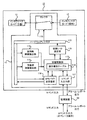
- the control system unit 11 is an example of a hardware register 110, a working side failure detection unit 111, a backup side failure detection unit 112, a switching control unit 113 which is an example of “selection means”, and “priority information”.
- the hardware register 110 stores a signal transferred from the interface card 12 when receiving a signal.
- the hardware register 110 sends the stored signal to the working side failure detection unit 111, the backup side failure detection unit 112.
- the data is output to the APS byte transmitting / receiving unit 116.
- the hardware register 110 stores therein a selector control signal transferred from the switching I / O setting unit 115 when transmitting a signal.
- the hardware register 110 outputs the stored selector control signal to the selector 118.
- the working side failure detection unit 111 detects the presence or absence of a failure occurring in the working line 21 or 23 based on a signal or the like transferred from the interface card 12.
- the backup side failure detection unit 112 detects the presence or absence of a failure that occurs in the backup line 22 or 24 based on a signal or the like transferred from the interface card 12.
- the switching control unit 113 detects the failure detection result in the active side failure detection unit 111 and the backup side failure detection unit 112, the APS byte 411 (see FIG. 4) received by the APS byte transmission / reception unit 116, and the command input from the monitoring device 30. Based on the above, switching of signal transmission paths in the transmission system 1 is controlled. For example, the switching control unit 113 switches from the working line 21 to the protection line 22 (or switching from the working line 23 to the protection line 24), and switches from the protection line 22 to the working line 21 (or from the protection line 24). Switching to the working line 23) is determined.
- the switching control unit 113 selects which of the working line 21 and the protection line 22 is used as a signal transmission path (or which of the work line 23 and the protection line 24 is used as a signal transmission path). To do.
- the switching control unit 113 instructs the switching I / O setting unit 115 to output an appropriate selector control signal so that the input / output of the selector 118 is appropriately switched.
- the priority table 114 is used for switching from the working line 21 to the protection line 22 (or switching from the working line 23 to the protection line 24) and switching from the protection line 22 to the working line 21 (or from the protection line 24 to the working line 24). It is a table showing a priority order (in other words, a determination condition) when determining whether or not to switch to the line 23).
- the priority table 114 may be stored in a memory (not shown) or the like in the switching control unit 113, or may be stored in a memory or the like arranged at another position.
- the switching I / O setting unit 115 outputs a selector control signal for switching input / output of the selector 118 to the hardware register 110 under the control of the switching control unit 113.
- the APS byte transmission / reception unit 116 acquires the APS byte 411 (see FIG. 4) included in the signal transferred from the interface card 12 and transfers the acquired APS byte 411 to the switching control unit 113. Further, the APS byte transmission / reception unit 116 is transmitted to the interface card 12 in response to the transmission instruction of the APS byte 411 output from the switching control unit 113 (that is, transmitted to the outside of the transmission device 10). APS byte 411 is added to signal).
- the command input unit 117 receives an input of a command (specifically, for example, a command related to a line switching request) input to the transmission apparatus 10 from an external operator or the like via the external monitoring apparatus 30, for example.
- the command input unit 117 outputs the input command to the switching control unit 113. Further, the command input unit 117 outputs a report including an alarm generated in the transmission device 10 and other various logs to the monitoring device 30.
- the selector 118 performs 1 + 1 switching by appropriately reading the selector control signal stored in the hardware register 110. That is, the selector 118 switches from the working line 21 to the protection line 22 (or switching from the working line 23 to the protection line 24), or switches from the protection line 22 to the working line 21 (or from the protection line 24 to the working line 24). Switching to the line 23).
- FIG. 2 illustrates the transmission apparatus 10 that performs 1 + 1 switching.
- the transmission apparatus 10 that performs 1: n switching may be applied to the transmission system 1 of the present embodiment.
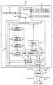
- the transmission apparatus 10 includes a plurality of working failure detection units 111_1 to 111_n corresponding to the number n of working lines and a working number corresponding to the number n of working lines. 2 is different from the transmission apparatus 10 shown in FIG. 2 in that a plurality of interface cards 12 for lines are provided.
- Other configurations of the transmission apparatus 10 that performs 1: n switching may be the same as those of the transmission apparatus 10 that performs 1 + 1 switching.
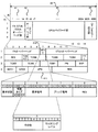
- FIG. 4 is a data structure diagram showing the data structure of the OTN frame 40.
- FIG. 5 is a data structure diagram showing the data structure of the APS byte 411 included in the OTN frame 40.
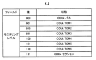
- FIG. 6 is a data structure diagram showing the data structure of the MFAS 412 included in the OTN frame 40.
- the OTN frame 40 includes an FA / OTUk / ODUk overhead part (Frame (Alignment / Optical channel Transport Unit k / Optical channel Data Unit k Overhead) 41 and an OPUk overhead part (Optical channel Payload Unit k Overhead). 42, an OPUk payload portion (OPUk Payload) 43, and an OTUk FEC: OTUk Forward Error Correction.
- the data structure of the OTN frame 40 is ITU-T G. 709.
- the FA / OTUk / ODUk overhead unit 41 has a frame size of 14 bytes ⁇ 4 rows corresponding to fields from the first column to the fourteenth column.
- the FA / OTUk / ODUk overhead unit 41 is used for transmission of the OTN frame 40, transmission quality management, and the like.
- the FA / OTUk / ODUk overhead unit 41 includes, for example, an FA overhead unit, MFAS (Multi Frame Alignment Signal) 412, OTUk overhead unit, and TCM 1 to TCM 6 (Tandem Connection Monitoring: Tandem connection monitoring).
- FTFL Fault Type & Fault Location reporting channel
- PM Path Monitoring
- EXP Experimental
- GCC1 to GCC2 General Communication Channel: General communication channel
- APS byte 411 APS byte 411
- RES Reserved
- the OPUk overhead unit 42 has a frame size of 2 bytes ⁇ 4 rows corresponding to the fields in the 15th and 16th columns.
- the OPUk overhead part 42 includes various information for controlling and managing the OPUk payload part 43.
- the OPUk overhead section 42 includes, for example, a PSI (Payload Structure Identifier), a mapping / concatenation section (Mapping & Concat. Specific), and the like.
- the OPUk payload section 43 has a frame size of 3808 bytes ⁇ 4 rows corresponding to the fields from the 17th column to the 3824th column.
- the OPUk payload section 43 includes a client signal that provides one or more services.
- the OTUk error correction unit 44 has a frame size of 256 bytes ⁇ 4 rows corresponding to the fields from the 3825th column to the 4080th column.
- the OTUk error correction unit 44 includes various types of information for correcting errors that occur during transmission of the OTN frame 40.
- the APS byte 411 and the MFAS 412 which are examples of information related to the switching of the transmission path in the present embodiment will be further described.
- the APS byte 411 includes a request state (Request / State) having a size of 4 bits, which is an example of “request state information”, a protection type (Protection Type) having a size of 4 bits, It includes a request signal (Requested Signal) having a size of 8 bits, a bridge signal (Bridged Signal) having a size of 8 bits, and a RES area having a size of 8 bits.
- the data structure of the APS byte 411 is ITU-T G. 873.1 etc.
- the request state indicates “LockoutLockof Protection (LO)”.
- the request state indicates “Forced Switch (FS)”.
- the request state indicates “Signal ⁇ Fail (SF)”.
- the request state indicates “1010” when the value is “Signal Degrade (SD)”.
- the request state indicates “Manual Switch (MS)”.
- the request state indicates “Wait-to-Restore (WTR)” when the value is “0110”.
- the request state indicates “Exercise (EXER)”.
- the request state indicates “Reverse request (RR)” when the value is “0010”.
- the request state indicates “Do ⁇ Not Revert (DNR) ”when the value is“ 0001 ”.
- the request state indicates “No ⁇ Request (NR)”.
- the protection type indicates “No APS Channel” when the value of the A field is “0”.
- the protection type indicates “APS Channel” when the value of the A field is “1”.
- the protection type indicates “1 + 1 switching” when the value of the B field is “0”.
- the protection type indicates “1: n switching” when the value of the B field is “1”.
- the protection type indicates “Unidirectional Switching” when the value of the C field is “0”.
- the protection type indicates “Bidirectional Switching” when the value of the C field is “1”.
- the protection type indicates “Non-revertive Operation” when the value of the D field is “0”.
- the protection type indicates “Revertive Operation” when the value of the D field is “1”.
- the request signal indicates a signal that another adjacent transmission device 10 (for example, near-end: NEND transmission device 10) requests to transmit by switching the transmission path.
- the bridge signal indicates a signal that is bridged by switching the transmission path. In any case, when the value is “0”, “Null Signal” is indicated, and when the value is “1” to “254”, “Normal Traffic Signal” is indicated, and the value is “255”. In this case, “Extra Traffic Signal” is indicated.
- the MFAS 412 includes a monitoring level (Monitoring Level) having a size of 3 bits and other information having a size of 5 bits.
- the monitoring level corresponds to a specific example of “section type information”. Which segment the APS byte 411 corresponds to which APS byte 411 (in other words, which of the OTN frames 40 including the APS byte 411 is It is the OTN frame 40 corresponding to the segment).
- the monitoring level indicates that the APS byte 411 is the APS byte 411 corresponding to the path.
- the value of the monitoring level is “001”, it indicates that the APS byte 411 is the APS byte 411 corresponding to TCM1.
- the monitoring level indicates that the APS byte 411 is the APS byte 411 corresponding to TCM2.
- the monitoring level indicates that the APS byte 411 is the APS byte 411 corresponding to TCM3.
- the monitoring level indicates that the APS byte 411 is the APS byte 411 corresponding to the TCM4.
- the monitoring level indicates that the APS byte 411 is the APS byte 411 corresponding to TCM5.
- the monitoring level indicates that the APS byte 411 is the APS byte 411 corresponding to TCM6.
- the monitoring level indicates that the APS byte 411 is the APS byte 411 corresponding to the section. That is, the segment to which the APS byte 411 corresponds can be changed for each OTN frame 40 by changing the value of the MFAS 412. In other words, the APS byte 411 can be transmitted in multiple frames by changing the value of the MFAS 412.
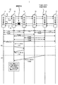
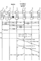
- FIG. 7 is a sequence diagram illustrating an example of the operation of the transmission apparatus 10 corresponding to the first operation example.
- FIG. 8 is a table showing an example of the priority order table 114 used in the first operation example.
- transmission device (# 1) 10, transmission device (# 2) 10, transmission device (# 3) 10, transmission device (# 4) 10 transmission
- the first operation example will be described by taking the operation on the transmission system 1 in which the device (# 5) 10 and the transmission device (# 6) 10) are connected to each other via the liner transmission line 20 as an example. More specifically, the transmission device (# 1) 10 and the transmission device (# 2) 10 are connected via the liner transmission path 20, and the transmission device (# 2) 10 and the transmission device (# 3) 10 are connected. The transmission device (# 3) 10 and the transmission device (# 4) 10 are connected via the liner transmission line 20, and the transmission device (# 4) 10 and the transmission device (# 5) are connected via the liner transmission line 20. ) 10 is connected via the liner transmission line 20, and the operation on the transmission system 1 in which the transmission device (# 5) 10 and the transmission device (# 6) 10 are connected via the liner transmission line 20 is an example. First, the first operation example will be described.
- the TCM is set as follows.
- the TCM 1 is set between the transmission device (# 1) 10 and the transmission device (# 3) 10 and between the transmission device (# 4) 10 and the transmission device (# 6) 10.
- the TCM 2 is set between the transmission device (# 1) 10 and the transmission device (# 4) 10.
- the TCM 3 is set between the transmission device (# 2) 10 and the transmission device (# 6) 10.
- the TCM 4 is set between the transmission device (# 3) 10 and the transmission device (# 5) 10.
- the TCM 6 is set between the transmission apparatus (# 2) 10 and the transmission apparatus (# 5) 10.
- the paths are between the transmission device (# 1) 10 and the transmission device (# 2) 10, between the transmission device (# 2) 10 and the transmission device (# 3) 10, and between the transmission device (# 3) 10 and the transmission device (# 3) 10.
- the section corresponds to a segment between the transmission apparatus (# 1) 10 and the transmission apparatus (# 6) 10.
- the APS byte transmission / reception unit 116 of the transmission apparatus (# 2) 10 In response to the failure that occurred in the working line 23 on the side from the transmission apparatus (# 3) 10 to the transmission apparatus (# 2) 10, the APS byte transmission / reception unit 116 of the transmission apparatus (# 2) 10 At this point, for the transmission apparatus (# 3) 10, the request state is “SF”, the request signal is “0 (standby)”, and the bridge signal is “1 (working)”. Send. At this time, in order to indicate that the APS byte 411 corresponds to a path, the MFAS 412 of the OTN frame 40 including the APS byte 411 is set to a value “000” indicating a path.
- the APS byte 411 including the request state, the request signal and the bridge signal and the MFAS 412 including the monitoring level are collectively referred to as “(request state) / (request signal) / (bridge “Signal) / (monitoring level)”. Therefore, the APS byte 411 transmitted from the transmission apparatus (# 2) 10 to the transmission apparatus (# 3) 10 is described by the notation “SF / 0/1 / path”.
- transmission apparatus (# 4) 10 receives transmission apparatus (# 3) 10 accommodated in TCM2 at time t11. In response to this, an APS byte 411 of “FS / 1/0 / TCM2” is transmitted.
- the transmission device (# 4) 10 sends an APS “FS / 1/0 / TCM2” to the other transmission devices (# 1) 10 and the transmission device (# 2) 10 accommodated in the TCM 2. Byte 411 may be transmitted.
- Both the APS byte 411 “SF / 0/1 / path” and the APS byte 411 “FS / 1/0 / TCM2” are transmitted to the transmission apparatus (# 3) 10. That is, the transmission apparatus (# 3) 10 has a plurality of switching requests (that is, transmission of a plurality of APS bytes 411) for a plurality of partially overlapping segments.
- the switching control unit 113 included in the transmission apparatus (# 3) 10 targets a plurality of partially overlapping segments based on the priority order table 114 that considers the priority of each of the plurality of segments. Any one of the plurality of switching requests is selected as a switching request for actually switching the transmission path.
- the switching control unit 113 included in the transmission device (# 3) 10 selects any one of the plurality of APS bytes 411 based on the priority table 114 that considers the priority of each of the plurality of segments.
- the APS byte 411 to be referred to is actually selected to switch the transmission path.
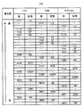
- FIG. 8 shows an example of the priority order table 114 that considers the priorities of the plurality of segments.
- the priority order table 114 sets the priorities of the plurality of segments so that the priorities become lower in the order of path, TCM, and section for the same request state.
- the priority table 114 includes a path switching request based on LO, a TCM switching request based on LO, a section switching request based on LO, a path switching request based on FS, and a path switching request based on SF.
- Path switching request based on SD TCM switching request based on FS, TCM switching request based on SF, TCM switching request based on SD, section switching request based on FS, section switching request based on SF, SD Section switching request based on MS, path switching request based on MS, TCM switching request based on MS, section switching request based on MS, path switching request based on WTR, TCM switching request based on WTR, based on WTR Section switching request, EXER-based path switching request, EXER-based TCM switching request, EX Section switching request based on R, path switching request based on RR, TCM switching request based on RR, section switching request based on RR, path switching request based on DNR, TCM switching request based on DNR, DNR
- the priority of each of the plurality of segments is set so that the priority becomes lower in the order of the section switching request based on NR, the path switching request based on NR, the TCM switching request based on NR, the TCM switching request
- the priority setting mode shown in FIG. 8 is an example, and the priority of each segment may be set to have an arbitrary priority. Further, considering that a maximum of six TCMs (that is, TCM1 to TCM6) are set in OTN, the priority order table 114 may further set the respective priority orders of TCM1 to TCM6.
- the priority of the APS byte 411 “SF / 0/1 / path” is higher than the priority of the APS byte 411 “FS / 1/0 / TCM2”.
- the switching control unit 113 included in the transmission apparatus (# 3) 10 switches the transmission path for the failure that has occurred in the working line 23 on the side from the transmission apparatus (# 3) 10 to the transmission apparatus (# 2) 10. Do. In other words, the switching control unit 113 included in the transmission apparatus (# 3) 10 does not respond to the transmission path switching request in the TCM 2 based on the FS from the transmission apparatus (# 4) 10.
- the APS byte transmission / reception unit 116 included in the transmission device (# 3) 10 transmits the APS byte 411 “RR / 1/1 / path” as a response to the transmission device (# 2) 10.
- the signal transmission path from the transmission device (# 3) 10 toward the transmission device (# 2) 10 is switched from the working line 23 to the protection line 24.
- the switching control unit 113 of the transmission apparatus (# 4) 10 that has made a transmission path switching request in the TCM2 based on the FS is within a certain time after the transmission of the APS byte 411 (specifically, for example, time When there is no response APS byte 411 transmitted (by t12), it is preferable to determine that the transmission path cannot be switched.
- the transmission apparatus 10 Based on the priority table 114 that considers the priority of each segment, the transmission path can be switched in response to any one switching request.
- the priority of the request state “SF” may be lower than the priority of the request state “FS”. Therefore, in the example shown in FIG. 7, the priority of the APS byte 411 “SF / 0/1 / path” is lower than the priority of the APS byte 411 “FS / 1/0 / TCM2”. It might be. Therefore, switching to the working line in TCM2 is performed. However, since a failure has occurred in the working line 23 of the path between the transmission apparatus (# 2) 10 and the transmission apparatus (# 3) 10 that partially overlaps with the TCM 2, switching to the working line in the TCM 2 Later signal transmission will not be performed properly. For this reason, in order to perform appropriate transmission in TCM2, the transmission apparatus 10 needs to switch the transmission path again. Accordingly, it is assumed that not only the optimal switching is not performed, but also an unnecessary switching request is repeatedly performed in order to perform the optimal switching.
- the transmission apparatus (# 3) 10 receives both the APS byte 411 “SF / 0/1 / path” and the APS byte 411 “FS / 0/1 / TCM2” simultaneously.
- both the APS byte 411 “SF / 0/1 / path” and the APS byte 411 “FS / 0/1 / TCM2” are not received at the same time (that is, when they are received before and after). Also, the effects described above can be enjoyed.
- FIG. 9 is a data structure diagram showing the data structure of the APS byte 411a used in the second operation example.
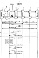
- FIG. 10 is a sequence diagram illustrating an example of the operation of the transmission apparatus 10 corresponding to the second operation example.
- FIG. 11 is a table showing an example of the priority order table 114a used in the second operation example.
- FIG. 12 is a sequence diagram illustrating another example of the operation of the transmission apparatus 10 corresponding to the second operation example.
- the APS byte 411a includes a source device ID 4111 for identifying the transmission device 10 that transmits the APS byte 411a in a partial field thereof.
- the source device ID 4111 is an example of “position information” and “identification information”.
- the source device ID 4111 may be included in the APS byte 411a regardless of whether the APS byte 411a corresponds to a path, the APS byte 411a corresponds to a TCM, or the APS byte 411a corresponds to a section. preferable. However, the source device ID 4111 may be included in any field in the OTN frame 40 other than the APS byte 411a.
- the source device ID 4111 included in the APS byte 411a is obtained from, for example, the transmission device 10 that has received the APS byte 411a from the transmission device 10 to which the received APS byte 411a is adjacent (that is, the transmission device 10 of NEND (Near END)). Used to determine whether it is being transmitted.
- the source device ID 4111 included in the APS byte 411a is, for example, that the transmission device 10 that has received the APS byte 411a has received the remote transmission device 10 that is not adjacent to the received APS byte 411a (that is, FEND (Far END ) Is used to determine whether or not it is transmitted from the transmission device 10).
- the transmission apparatus 10 considers the priority according to whether or not the APS byte 411a is transmitted from the FEND transmission apparatus 10 in addition to the priorities of the plurality of segments described above. Then, any one of the plurality of APS bytes 411a to be received is selected as the APS byte 411a to be referred to in order to actually switch the transmission path. In other words, the transmission apparatus 10 considers the priority according to whether or not the switching request is made from the FEND transmission apparatus 10 in addition to the priority of each of the plurality of segments described above, and thereby the plurality of switching requests. Is selected as a switching request for actually switching the transmission path.
- the second operation example will be described with specific examples.
- the second operation example will be described by taking the operation on the same transmission system 1 as the transmission system 1 shown in FIG. 7 as an example.
- the request status, the request signal, the bridge signal, the APS byte 411a including the source device ID 4111 and the MFAS 412 including the monitoring level are collectively expressed as “(request status) / (request signal ) / (Bridge signal) / (source device ID 4111) / (monitoring level) ”.
- the switching control unit 113 included in the transmission device (# 3) 10 When the APS byte 411 a including the source device ID 4111 is received, the switching control unit 113 included in the transmission device (# 3) 10 has the device ID of the transmission device 10 adjacent to the transmission device (# 3) 10 as “2”. Recognize that there is. The switching control unit 113 included in the transmission apparatus (# 3) 10 switches the transmission path for a failure that has occurred in the working line 23 on the side from the transmission apparatus (# 3) 10 to the transmission apparatus (# 2) 10. Do. That is, the signal transmission path from the transmission apparatus (# 3) 10 toward the transmission apparatus (# 2) 10 is switched from the working line 23 to the protection line 24.
- the APS byte 411a is transmitted.
- the switching control unit 113 included in the transmission device (# 2) 10 receives the APS byte 411a including the source device ID 4111 and the device ID of the transmission device 10 adjacent to the transmission device (# 2) 10 is “ 3 ”.
- An APS byte 411a “TCM6” may be transmitted.
- the switching control unit 113 included in the transmission device (# 2) 10 performs priority according to the priority of each of the plurality of segments and whether the APS byte 411a is transmitted from the FEND transmission device 10. Based on the priority order table 114a in consideration of the degree, any one of a plurality of switching requests targeting a plurality of partially overlapping segments is selected as a switching request for actually switching the transmission path.
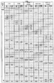
- FIG. 11 shows an example of the priority table 114a in which the priority of each of the plurality of segments and the priority according to whether the APS byte 411a is transmitted from the FEND transmission apparatus 10 are taken into account.
- the priority order table 114a employs the priority order table shown in FIG. 8 for the priority order of request states alone.
- the priority order table 114a has a transmission device 10 in which the APS byte 411a is FEND so that the priority becomes lower in the order of path, TCM, TCM (FEND), section, and section (FEND). The priority is set according to whether or not the message is transmitted from.
- the priority table 114a sets the priority when the APS byte 411a is transmitted from the FEND transmission apparatus 10 to be lower than the priority when the APS byte 411a is transmitted from the NEND transmission apparatus 10. ing.
- the priority table 114a includes a path switching request, a TCM switching request from the NEND transmission apparatus 10, a TCM switching request from the FEND transmission apparatus 10, and a section switching request from the NEND transmission apparatus 10. The priority according to whether or not the APS byte 411a is transmitted from the FEND transmission apparatus 10 is set so that the priority becomes lower in the order of section switching requests from the FEND transmission apparatus 10.
- the priority setting mode shown in FIG. 11 is an example, and the priority of each segment and whether or not the APS byte 411a is transmitted from the FEND transmission apparatus 10 so as to have an arbitrary priority order.
- a priority may be set.
- the transmission device (# 5) 10 is replaced with a command for switching the transmission path to the working line in the TCM 6 based on FS (Forced-Switch).
- # 3 A case where a command for switching the transmission path to the working line in the TCM 6 based on LO (Lockout of Protection) is input to 10 will be described.
- the transmission system 1 shown in FIG. 12 is different from the transmission system 1 shown in FIG. 10 in that the TCM 6 is set between the transmission device (# 2) 10 and the transmission device (# 3) 10. Different.
- the transmission apparatus ( # 3) As shown in FIG. 12, for a failure occurring in the working line 23 on the side from the transmission apparatus (# 3) 10 to the transmission apparatus (# 2) 10, the transmission apparatus ( # 3) The transmission path of the signal on the side from 10 to the transmission apparatus (# 2) 10 is switched from the working line 23 to the protection line 24.
- the transmission apparatus 10 similarly to the first operation example, the transmission apparatus 10 generates a plurality of switching requests for a plurality of types of segments (that is, paths, TCMs, and sections).
- the transmission path can be switched in response to any one switching request on the basis of the priority order table 114 considering the priorities of the plurality of types of segments.
- the transmission device 10 (for example, the transmission device 10 that terminates the TCM, such as the transmission device (# 2) 10 in FIG. 10 and FIG. 12) requests the switching (or the APS byte 411a). Can be selected from among a plurality of switching requests, depending on whether or not the transmission is performed by the FEND transmission apparatus 10. Therefore, when the transmission apparatus 10 switches the transmission path in the path with high priority, the transmission apparatus 10 switches the transmission path in the TCM or section requested from the FEND transmission apparatus 10 with low priority. You do n’t have to. Alternatively, the transmission apparatus 10 is requested by the FEND transmission apparatus 10 having a low priority when switching the transmission path in the TCM or section requested by the NEND transmission apparatus 10 having a high priority.
- the transmission apparatus 10 that terminates a TCM or a section that crosses a plurality of paths does not adversely affect the switching of the transmission path that is performed in an intermediate path that partially overlaps the TCM or section. No more. Therefore, the transmission apparatus 10 can switch the transmission path more preferably.
- FIG. 13 is a data structure diagram showing the data structure of the APS byte 411b used in the third operation example.
- FIG. 14 is a sequence diagram illustrating an example of the operation of the transmission apparatus 10 corresponding to the third operation example.
- FIG. 15 is a sequence diagram illustrating another example of the operation of the transmission apparatus 10 corresponding to the third operation example.
- the APS byte 411b is switched in a part of the field between the source device ID 4111 for identifying the transmission device 10 that transmits the APS byte 411b and the APS byte 411b. It includes transfer information 4112 for identifying whether the request itself is indicated or a notification to another transmission apparatus 10 indicating that switching is being performed.
- the APS byte 411b includes the source device ID 4111 from the first bit to the sixth bit in the eighth column, and the transfer information 4112 in the seventh bit of the eighth column. ing. That is, in the example shown in FIG. 9, the transfer information 4112 is disclosed as an example of a 1-bit flag.
- the APS byte 411b indicates a switching request (that is, the transmission path is switched to the transmission apparatus 10 that receives the APS byte 411b). Requesting).
- the transfer information 4112 is “1 (FEND)”
- the APS byte 411b notifies the other transmission apparatus 10 that the switching indicated by the APS byte 411 is being performed. .
- the transmission device 10 that has received the APS byte 411b transmits the received APS byte 411b from the transmission device 10 of NEND or FEND. It is used to determine whether The source device ID 4111 included in the APS byte 411b may be used by the transmission device 10 that has received the APS byte 411b to determine from which transmission device 10 the received APS byte 411b is transmitted. Good.
- the transfer information 4112 included in the APS byte 411b indicates that the transmission apparatus 10 that has received the APS byte 411b switches the transmission path according to the received APS byte 411b, or the transmission path according to the received APS byte 411b. This is used to determine whether to recognize that the switching is performed by another transmission apparatus 10. For example, if the transfer information 4112 is “0”, the transmission apparatus 10 performs switching of the transmission path according to the received APS byte 411b (for example, switching based on the first and second operation examples described above). To decide. On the other hand, for example, if the transfer information 4112 is “1”, the transmission apparatus 10 only recognizes that another transmission apparatus 10 is switching the transmission path according to the received APS byte 411b. Decide that.
- the transmission apparatus 10 can also newly switch the transmission path performed by another transmission apparatus 10 recognized by referring to the transfer information 4112 by referring to the priority table 114 or 114a described above. It is preferable to compare the priority with the APS byte 411 to be transmitted or received and a switching request by a command or the like. In other words, the transmission apparatus 10 switches the transmission path to be newly transmitted or to be performed by the switching request by the received APS byte 411 or the command or the like with respect to the transmission path switching performed by another transmission apparatus 10. It is preferable to determine whether to give priority.
- the transmission of the APS byte 411b with the transfer information 4112 set to “1” is performed by the transmission apparatus 10 corresponding to the intermediate node of the TCM or section (in other words, a node that is not a terminal node or a node at both ends). It is preferable.
- the transmission of the APS byte 411b with the transfer information 4112 set to “1” is a transmission performed by the transmission apparatus 10 corresponding to the intermediate node of the TCM or section and switching the transmission path in the path. Preferably performed by the apparatus 10.
- any transmission device 10 that actually switches the transmission path may transmit the APS byte 411b after setting the transfer information 4112 to “1”.
- the third operation example will be described by taking the operation on the same transmission system 1 as the transmission system 1 illustrated in FIG. 12 as an example.
- a request state, a request signal, a bridge signal, an APS byte 411a including a source device ID 4111 and transfer information 4112, and an MFAS 412 including a monitoring level are collectively expressed as “(request state)”. / (Request signal) / (Bridge signal) / (Source device ID 4111) / (Transfer information 4112) / (Monitoring level) ”.
- the switching control unit 113 included in the transmission apparatus (# 2) 10 receives the APS byte 411b including the source apparatus ID 4111, and the apparatus ID of the transmission apparatus 10 adjacent to the transmission apparatus (# 2) 10 is “3”. Recognize that there is. In addition, the switching control unit 113 included in the transmission apparatus (# 2) 10 determines to switch the transmission path according to the received APS byte 411b by receiving the APS byte 411b in which the transfer information 4112 is “0”. To do. That is, the switching control unit 113 included in the transmission device (# 2) 10 switches the transmission path for a failure that has occurred in the working line 23 on the side from the transmission device (# 2) 10 to the transmission device (# 3) 10. Do. Therefore, the signal transmission path from the transmission apparatus (# 3) 10 toward the transmission apparatus (# 2) 10 is switched from the working line 23 to the protection line 24.
- the switching control unit 113 included in the transmission device (# 3) 10 receives the APS byte 411b including the source device ID 4111 and the device ID of the transmission device 10 adjacent to the transmission device (# 3) 10 is “ 2 ”.
- the transmission device (# 2) 10 indicates that the transmission path is switched at the time t32, and the TCM or section accommodating the transmission device (# 2) 10 as an intermediate node. Is notified to another transmission apparatus 10 accommodated in the network. This notification is performed by transmitting the APS byte 411b in which the transfer information 4112 is “1”. Specifically, in the example illustrated in FIG. 14, the transmission apparatus (# 2) 10 is accommodated as an intermediate node in TCM1, TCM2, and the section.
- the transmission apparatus (# 1) 10 recognizes that the transmission path is switched based on the SF in at least some sections (for example, paths) of the TCM1, the TCM2, and the section. Can do. That is, the transmission apparatus (# 1) 10 recognizes whether or not the transmission path is switched in at least some sections (for example, paths) of the TCM1, TCM2 and sections that cannot be directly recognized by the transmission apparatus (# 1). can do. Accordingly, the transmission apparatus (# 1) 10 has an adverse effect on the switching of the transmission path or when the transmission path can be switched while considering whether the transmission path is switched in a path overlapping with TCM1, TCM2, and the section. If not, transmission paths can be selectively switched between TCM1, TCM2 and sections. Therefore, appropriate transmission path switching can be performed.
- the fact that the transmission device (# 3) 10 is switching the transmission path at the time t32 indicates that the transmission device (# 3) 10 is accommodated as an intermediate node. Notification is given to the other transmission apparatuses 10 accommodated in the section. This notification is performed by transmission of the APS byte 411b in which the transfer information 4112 is “1” by the APS byte transmission / reception unit 116. Specifically, in the example illustrated in FIG. 14, the transmission apparatus (# 3) 10 is accommodated as an intermediate node in TCM2, TCM3, and the section.
- the transmission apparatus (# 4) 10 recognizes that the transmission path switching based on the SF is performed in at least some sections (for example, paths) of the TCM2, the TCM3, and the section. Can do. Therefore, the transmission apparatus (# 4) 10 has an adverse effect on the switching of the transmission path or when the transmission path can be switched while considering whether the transmission path is switched in a path overlapping with TCM2, TCM3, and the section. If not, transmission paths can be selectively switched between TCM2, TCM3 and sections. Therefore, appropriate transmission path switching can be performed.
- the transmission path is switched based on the SF in at least a part of the TCM 3 and the section (for example, a path). I can recognize that. Therefore, the transmission device (# 5) 10 and the transmission device (# 6) 10 are used when the transmission path can be switched while considering whether the transmission path is switched in a path overlapping with the TCM 3 and the section, or when transmission is possible. When the path switching does not have an adverse effect, the transmission path can be selectively switched between the TCM 3 and the section. Therefore, appropriate transmission path switching can be performed.
- the transmission apparatus 10 uses the APS byte 411b including the transfer information 4112 set to “1” when the transmission path is switched according to a request state having a relatively low priority. It is not necessary to notify other transmission apparatuses 10 that the transmission path is switched. In other words, the transmission apparatus 10 is set to “1” when the transmission path is switched according to a part of the request state having relatively high priority (for example, LO, FS, SF, SD). The other transmission apparatus 10 may be notified that the transmission path is switched using the APS byte 411b including the transfer information 4112 that has been transferred. If the notification is made in this way, a notification that the transmission path is switched according to a request state having a low priority is not transmitted, so that the communication load on the liner transmission path 20 can be reduced.
- a part of the request state having relatively high priority for example, LO, FS, SF, SD
- the transmission apparatus 10 switches the transmission path according to a request state having a relatively low priority
- the APS byte having a relatively high priority notified from the other transmission apparatus 10 411b may be transferred to another transmission apparatus 10 as it is.
- the operation on the transmission system 1 shown in FIG. 15 will be described as an example.
- the transmission apparatus (# 4) 10 is based on MS (Manual Switch). A case will be described in which a command for switching the transmission path to the working line in the path between the transmission apparatus (# 4) 10 and the transmission apparatus (# 5) 10 is input.
- the transmission apparatus (# 4) 10 in response to the input of the transmission path switching command in the path based on the MS, the transmission apparatus (# 4) 10 sends the transmission apparatus (# 5) 10 to the transmission apparatus (# 5) 10 at time t33.
- the APS byte 411b “MS / 0/1 / ID 4 / NEND (0) / path” is transmitted.
- the switching control unit 113 included in the transmission device (# 5) 10 receives the APS byte 411b including the source device ID 4111, and the device ID of the transmission device 10 adjacent to the transmission device (# 5) 10 is “4”. Recognize that there is. In addition, the switching control unit 113 included in the transmission apparatus (# 5) 10 determines to switch the transmission path according to the received APS byte 411b by receiving the APS byte 411b in which the transfer information 4112 is “0”. To do. That is, the switching control unit 113 included in the transmission device (# 5) 10 switches the transmission path in the path between the transmission device (# 4) 10 and the transmission device (# 5) 10.
- the switching control unit 113 included in the transmission device (# 4) 10 receives the APS byte 411b including the source device ID 4111 and the device ID of the transmission device 10 adjacent to the transmission device (# 4) 10 is “ 5 ”.
- APS byte 411b (refer to dotted line arrow in FIG. 15)
- APS byte 411b (refer to dotted line arrow in FIG. 15)
- MS / 1/1 / ID 4 / FEND (1) / section” It is not necessary to transfer to the transmission apparatus 10.
- the transmission apparatus (# 4) 10 is accommodated as an intermediate node in the TCM 4 in addition to the TCM 3 and the section.
- the transmission apparatus (# 5) 10 is accommodated in the TCM 1 as an intermediate node in addition to the TCM 3 and the section.
- FIG. 16 is a sequence diagram illustrating an example of the operation of the transmission apparatus 10 corresponding to the fourth operation example.
- the transmission apparatus 10 that switches the transmission path in the TCM or section notifies the path that the transmission path is switched by transmitting the APS byte 411b to the path.
- the fourth operation example will be described using the operation on the same transmission system 1 as the transmission system 1 illustrated in FIG. 12 as an example.
- a transmission path switching command in TCM 3 based on FS is input to the transmission apparatus (# 2) 10.
- the transmission apparatus 10 accommodated in the TCM 3 (in other words, the path in which each transmission apparatus 10 is accommodated (in other words, For example, it notifies other transmission apparatuses 10 adjacent to each other via a path that the transmission path is switched in the TCM 3 described above.
- the transmission device (# 2) 10, the transmission device (# 3) 10, the transmission device (# 4) 10, the transmission device (# 5) 10, and the transmission device (# 6) 10 are accommodated in the TCM 3. Has been.
- the transmission apparatus 10 can switch the transmission path described above by simpler processing.
Landscapes
- Engineering & Computer Science (AREA)
- Computer Networks & Wireless Communication (AREA)
- Signal Processing (AREA)
- Time-Division Multiplex Systems (AREA)
- Data Exchanges In Wide-Area Networks (AREA)
- Maintenance And Management Of Digital Transmission (AREA)
Abstract
伝送装置(10)は、少なくとも一部の区間が重複する複数種類の伝送区間を対象とした切替要求を取得する取得手段(116、117)と、複数種類の伝送区間の夫々に対応する優先度を示す優先度情報(114)に基づいて、複数種類の伝送区間を対象とした切替要求のうちのいずれか一つを選択する選択手段(113)と、選択された切替要求に応じた伝送経路の切り替えを行う切替手段(115、118)とを備える。
Description
本発明は、例えば信号の送信や受信を行う伝送装置及び方法に関し、より具体的には例えば基幹伝送路としてのバックボーン回線上での信号の送信や受信を行う伝送装置及び方法に関する。
バックボーン回線等の基幹伝送路又はその他の伝送路等に採用される通信規格として、ITU-T(International Telecommunication Union Telecommunication Standardization Sector)勧告のOTN(Optical Transport Network)が提案されている。OTNでは、伝送路の信頼性や運用性の向上のために、伝送路に対して設定された複数の回線(例えば、現用回線及び予備回線)の切り替えが行われる。複数の回線の切り替えの方式として、1+1切替や1:n切替等が存在する。複数の回線の切り替えは、OTNフレーム中に含まれるAPS(Automatic Protection Switching)バイト(或いは、APSチャネル)を各伝送装置が参照することによって行われる。
一方で、OTNでは、伝送路の階層化概念として、SDH(Synchronous Digital Hierarchy)やSONET(Synchronous Optical Network)等で採用されていたパス及びセクションというセグメント(伝送区間)の概念に加えて、TCM(Tandem Connection Monitoring)という新たなセグメントの概念が導入されている。TCMは、伝送路上の任意の位置の又は任意の長さのセグメントに対して自由に設定することができる。つまり、TCMを導入することによって、ネットワークプロバイダやユーザごとに固有のセグメントを設定することができる。このため、ネットワークプロバイダやユーザごとに固有のセグメントに対して、障害の発生状況や回線品質等のモニタリングを行うことができる。
OTNでは、MFAS(Multi Frame Alignment Signal)を用いることで、複数種類のセグメントの夫々に対して個別にAPSバイトを送信することができる。従って、上述した1+1切替や1:n切替は、MFAS及びAPSバイトに応じて、パスの単位やセクションの単位やTCMの単位で行われる。しかしながら、現状の1+1切替や1:n切替では、パスという単一のセグメントに対する回線の切り替えが考慮されているに過ぎない。このため、異なる複数種類のセグメントに対して回線の切替要求が生じた場合には、切り替えの完了(言い換えれば、障害が生じている回線の救済)までの時間が相対的に長くなってしまったり、最適な切り替えが行われなくなってしまったり、或いは不要な切り替えが発生してしまいかねないという技術的な問題点が生じてしまう。
例えば、第1の伝送装置と第2の伝送装置との間のパスに生じた障害に起因した現用回線から予備回線への切替要求が発生した後に、当該第1及び第2の伝送装置を中間ノードとして含むTCMに対してFS(Forced Switch)による予備回線から現用回線への切替要求が発生した場合について検討する。この場合、第1の伝送装置と第2の伝送装置との間のパスでは、現用回線から予備回線への切り替えが行われる。一方で、第1及び第2の伝送装置を中間ノードとして含むTCMでは、予備回線から現用回線への切り替えが行われる。しかしながら、第1の伝送装置と第2の伝送装置との間のパスでは現用回線に障害が発生しているため、TCMでの現用回線への切り替えによって、その後の信号の正常な伝送が困難になってしまう。従って、必ずしも最適な切り替えが行われなくなってしまう。
加えて、TCMという新たなセグメントの導入に限らず、複数種類のセグメントが導入されている場合には、上述した技術的な問題点が生じ得る。つまり、パス及びセクションという概念を採用しているSDHやSONETにおいても、パスに対する切替要求とセクションに対する切替要求とが生じた場合には、同様の技術的な問題点が生じかねない。
本発明が解決しようとする課題には上記のようなものが一例として挙げられる。本発明は、例えば異なる種類の伝送区間に対する切替要求が生じた場合にも、伝送経路の切り替えを適切に行うことが可能な伝送装置及び方法を提供することを目的とする。
上記課題は、取得手段と選択手段と切替手段とを備える伝送装置によって解決される。取得手段は、少なくとも一部の区間が重複する複数種類の伝送区間を対象とした信号の伝送経路の切替要求を取得する。選択手段は、優先度(例えば、複数種類の伝送区間の夫々に対応する優先度)を示す優先度情報に基づいて、複数の切替要求(例えば、複数種類の伝送区間を対象とした切替要求)のうちのいずれか一つを選択する。切替手段は、選択手段によって選択された一つの切替要求に応じた伝送経路の切り替えを行う。
上記課題は、取得工程と選択工程と切替工程とを備える伝送方法によって解決される。取得工程では、上述した取得手段が行う動作と同様の動作が行われる。選択工程では、上述した選択手段が行う動作と同様の動作が行われる。切替工程では、上述した切替手段が行う動作と同様の動作が行われる。
以上説明した伝送装置によれば、複数種類の伝送区間を対象とした切替要求が生じた場合には、優先度を示す優先度情報に基づいて、いずれか一つの切替要求に応じた伝送経路の切り替えが行われる。このため、複数種類の伝送区間を対象とした切替要求(つまり、複数の切替要求)が生じた場合であっても、複数の切替要求を実行する順番等に依存することなく、伝送区間の優先度に応じた適切な伝送経路の切り替えが行われる。言い換えれば、上述の伝送装置によれば、伝送経路の切り替えの完了(言い換えれば、障害が生じている回線の救済)までの時間が相対的に長くなってしまったり、最適な切り替えが行われなくなってしまったり、或いは不要な切り替えが発生してしまいかねないという技術的な問題点が生ずる不都合を好適になくすないしは抑制することができる。
一例として、例えば、第1の伝送装置と第2の伝送装置との間の第1の伝送区間(例えば、パス)に生じた障害に起因した現用回線から予備回線への第1の切替要求、並びに当該第1及び第2の伝送装置を中間ノードとして含む第2の伝送区間(例えば、TCM)に対してFSによる予備回線から現用回線への第2の切替要求が発生した場合について検討する。また、優先度情報は、第1の伝送区間の優先度が第2の伝送区間の優先度よりも高いことを示しているものとする。この場合、第1の切替要求に応じて、第1の伝送装置と第2の伝送装置との間の第1の伝送区間では、現用回線から予備回線への切り替えが行われる。一方で、第2の切替要求は、第1の切替要求と比較して優先度が相対的に低い第2の伝送区間に対する切替要求である。このため、第1及び第2の伝送装置を中間ノードとして含む第2の伝送区間では、予備回線から現用回線への切り替えが行われない。このため、第1の伝送区間で障害が発生している状態で第2の伝送区間での現用回線への切り替えが行われてしまうことによって、第1の伝送装置と第2の伝送装置との間の信号の正常な伝送が困難になってしまうという不都合が生ずることはなくなる。
以上説明した伝送方法によれば、上述した伝送装置が享受する効果と同様の効果を享受することができる。
以下、本発明を実施するための最良の形態を、図面に基づいて説明する。尚、以下の説明では、ITU-T(International Telecommunication Union Telecommunication Standardization Sector)勧告のOTN(Optical Transport Network)に準拠している伝送装置を例にあげて説明を進める。
(1)伝送システムの構成
図1を参照して、本実施形態の伝送装置10を備える伝送システム1の構成について説明する。図1は、本実施形態の伝送システム1の構成の一例を示すブロック図である。
図1を参照して、本実施形態の伝送装置10を備える伝送システム1の構成について説明する。図1は、本実施形態の伝送システム1の構成の一例を示すブロック図である。
図1に示すように、伝送システム1は、複数の伝送装置10と、ライナー伝送路20とを備えている。図1に示す伝送システム1の構成は一例であり、その他の構成を有する伝送システム(例えば、リング伝送路を介して複数の伝送装置が接続されている伝送システム等)に対して、以下に説明する伝送装置10を適用してもよい。
複数の伝送装置10は、ライナー伝送路20を介して相互に接続されている。複数の伝送装置10の夫々は、ライナー伝送路20を用いて、他の伝送装置10との間での所定の信号(例えば、後述するOTNフレーム40:図4参照)の送受信を行うことができる。図1では、5つの伝送装置10(具体的には、伝送装置(#1)10、伝送装置(#2)10、伝送装置(#3)10、伝送装置(#4)10及び伝送装置(#5)10)を備える例が開示されているが、図1に示す伝送装置10の数は一例である。伝送システム1は、任意の数の伝送装置10を備えていてもよい。
ライナー伝送路20は、複数の伝送装置10間での信号の送受信を行うための伝送路である。ライナー伝送路20は、例えば光ファイバ等を含んでいる。図1に示す例では、1つの伝送装置10から見て、信号の送信に用いられる光ファイバ及び信号の受信に用いられる光ファイバを含む例を示している。ライナー伝送路20は、その帯域のうちの一部が現用回線21又は23として利用され、その帯域のうちの他部が予備回線22又は24として使用される。図1では、1つの伝送装置10から見て、信号の送信(又は、受信)に用いられる光ファイバの帯域のうちの一部が現用回線21として利用され、当該光ファイバの帯域のうちの他部が予備回線22として使用される例を示している。同様に、図1では、1つの伝送装置10から見て、信号の受信(又は、送信)に用いられる光ファイバの帯域のうちの一部が現用回線23として利用され、当該光ファイバの帯域のうちの他部が予備回線24として使用される例を示している。
伝送システム1は、伝送すべき信号の伝送経路に対する階層化概念を採用している。本実施形態では、伝送システム1は、パス、TCM(Tandem Connection Monitoring:OTNでは、最大6つのTCM)及びセクションという3種類の階層化されたセグメント(伝送区間)を採用している。尚、図1に示す階層化されたセグメントは一例であり、他のセグメントの概念を採用してもよいし、より多くの種類の若しくはより少ない種類のセグメントの概念を採用してもよい。
(2)伝送装置の構成
図2を参照して、本実施形態の伝送装置10の構成について説明する。図2は、本実施形態の伝送装置10の構成の一例を示すブロック図である。
図2を参照して、本実施形態の伝送装置10の構成について説明する。図2は、本実施形態の伝送装置10の構成の一例を示すブロック図である。
図2に示すように、伝送装置10は、伝送装置10の動作を制御又は管理する制御系ユニット11と、制御系ユニット11の制御下でライナー伝送路20を介して伝送装置10の外部との間で信号を送受信するインタフェースカード12とを備えている。図2では、現用回線21及び23用のインタフェースカード12並びに予備回線22及び24用のインタフェースカード12を備える例が開示されている。つまり、図2では、1本の現用回線21(或いは、23)と1本の予備回線22(或いは、24)とを切り替える1+1切替を行う伝送装置10の例が開示されている。制御系ユニット11及びインタフェースカード12の夫々は、例えば、バックワイヤリングボード(Back Wiring Board)を背面に搭載しているブックシェルフ型の筐体に対して実装される。
制御系ユニット11は、ハードウェアレジスタ110と、現用側障害検出部111と、予備側障害検出部112と、「選択手段」の一例である切替制御部113と、「優先度情報」の一例である優先順位テーブル114と、「切替手段」の一例である切替I/O(Input / Output)設定部115と、「取得手段」、「送信手段」及び「受信手段」の一例であるAPS(Automatic Protection Switching:自動保護切替)バイト送受信部116と、「取得手段」の一例であるコマンド入力部117と、セレクタ118とを備えている。
ハードウェアレジスタ110は、信号の受信時には、インタフェースカード12から転送される信号を内部に格納する。ハードウェアレジスタ110は、現用側障害検出部111、予備側障害検出部又はAPSバイト送受信部116からの読み取り要求に応じて、当該格納した信号を現用側障害検出部111、予備側障害検出部112又はAPSバイト送受信部116に対して出力する。ハードウェアレジスタ110は、信号の送信時には、切替I/O設定部115から転送されるセレクタ制御信号を内部に格納する。ハードウェアレジスタ110は、当該格納したセレクタ制御信号をセレクタ118に対して出力する。
現用側障害検出部111は、インタフェースカード12から転送される信号等に基づいて、現用回線21又は23に生ずる障害の有無を検出する。
予備側障害検出部112は、インタフェースカード12から転送される信号等に基づいて、予備回線22又は24に生ずる障害の有無を検出する。
切替制御部113は、現用側障害検出部111及び予備側障害検出部112における障害の検出結果やAPSバイト送受信部116が受信するAPSバイト411(図4参照)や監視装置30から入力されるコマンドに基づいて、伝送システム1における信号の伝送経路の切り替えを制御する。例えば、切替制御部113は、現用回線21から予備回線22への切り替え(或いは、現用回線23から予備回線24への切り替え)や、予備回線22から現用回線21への切り替え(或いは、予備回線24から現用回線23への切り替え)を行うか否かを決定する。或いは、例えば、切替制御部113は、現用回線21及び予備回線22のいずれを信号の伝送経路として用いるか(或いは、現用回線23及び予備回線24のいずれを信号の伝送経路として用いるか)を選択する。切替制御部113は、伝送経路の切り替えを行う場合には、セレクタ118の入出力を適切に切り替えるよう、切替I/O設定部115に対して適切なセレクタ制御信号を出力するよう指示する。
優先順位テーブル114は、現用回線21から予備回線22への切り替え(或いは、現用回線23から予備回線24への切り替え)や、予備回線22から現用回線21への切り替え(或いは、予備回線24から現用回線23への切り替え)を行うか否かを決定する際の優先順位(言い換えれば、決定条件)を示すテーブルである。優先順位テーブル114は、切替制御部113内の不図示のメモリ等に格納されていてもよいし、その他の位置に配置されるメモリ等に格納されてもよい。
切替I/O設定部115は、切替制御部113の制御の下に、セレクタ118の入出力を切り替えるためのセレクタ制御信号をハードウェアレジスタ110に対して出力する。
APSバイト送受信部116は、インタフェースカード12から転送される信号に含まれるAPSバイト411(図4参照)を取得すると共に、取得したAPSバイト411を切替制御部113に対して転送する。また、APSバイト送受信部116は、切替制御部113から出力されるAPSバイト411の送信指示に応答して、インタフェースカード12に対して転送される信号(つまり、伝送装置10の外部に送信される信号)に対してAPSバイト411を付加する。
コマンド入力部117は、例えば外部の監視装置30を介して外部のオペレータ等から伝送装置10に対して入力されるコマンド(具体的には、例えば、回線の切替要求に関するコマンド)の入力を受け付ける。コマンド入力部117は、入力されたコマンドを切替制御部113に対して出力する。また、コマンド入力部117は、伝送装置10に発生したアラームやそのほか各種ログを含むレポートを監視装置30に対して出力する。
セレクタ118は、ハードウェアレジスタ110に格納されたセレクタ制御信号を適宜読み取ることで、1+1切替を行う。つまり、セレクタ118は、現用回線21から予備回線22への切り替え(或いは、現用回線23から予備回線24への切り替え)や、予備回線22から現用回線21への切り替え(或いは、予備回線24から現用回線23への切り替え)を行う。
図2では、1+1切替を行う伝送装置10について説明している。しかしながら、1:n切替を行う伝送装置10を本実施形態の伝送システム1に対して適用してもよい。1:n切替を行う場合には、図3に示すように、伝送装置10は、現用回線の数nに応じた複数の現用障害検出部111_1から111_nと、現用回線の数nに応じた現用回線用の複数のインタフェースカード12を備えるという点で、図2に示す伝送装置10とは異なっている。1:n切替を行う伝送装置10のその他の構成については、1+1切替を行う伝送装置10と同様であってもよい。
(3)OTNフレームのデータ構造
図4から図6を参照して、本実施形態の伝送システム1上で送受信される信号であるOTNフレーム40のデータ構造について説明する。図4は、OTNフレーム40のデータ構造を示すデータ構造図である。図5は、OTNフレーム40中に含まれるAPSバイト411のデータ構造を示すデータ構造図である。図6は、OTNフレーム40中に含まれるMFAS412のデータ構造を示すデータ構造図である。
図4から図6を参照して、本実施形態の伝送システム1上で送受信される信号であるOTNフレーム40のデータ構造について説明する。図4は、OTNフレーム40のデータ構造を示すデータ構造図である。図5は、OTNフレーム40中に含まれるAPSバイト411のデータ構造を示すデータ構造図である。図6は、OTNフレーム40中に含まれるMFAS412のデータ構造を示すデータ構造図である。
図4に示すように、OTNフレーム40は、FA/OTUk/ODUkオーバーヘッド部(Frame Alignment / Optical channel Transport Unit k /Optical channel Data Unit k Overhead)41と、OPUkオーバーヘッド部(Optical channel Payload Unit k Overhead)42と、OPUkペイロード部(OPUk Payload)43と、OTUkエラー訂正部(OTUk FEC : OTUk Forward Error Correction)44を含んでいる。OTNフレーム40のデータ構造は、ITU-T G.709によって定義されている。
FA/OTUk/ODUkオーバーヘッド部41は、第1列目から第14列目までのフィールドに相当する14バイト×4行のフレームサイズを有している。FA/OTUk/ODUkオーバーヘッド部41は、OTNフレーム40の伝送及び伝送品質の管理等に用いられる。FA/OTUk/ODUkオーバーヘッド部41には、例えば、FAオーバーヘッド部や、MFAS(Multi Frame Alignment Signal:マルチフレームアライメント信号)412や、OTUkオーバーヘッド部や、TCM1からTCM6(Tandem Connection Monitoring:タンデムコネクションモニタリング)や、FTFL(Fault Type & Fault Location reporting channel:フォールトタイプ&フォールト位置報告チャネル)や、PM(Path Monitoring:パスモニタリング)や、EXP(Experimental:エクスペリメンタル)や、GCC1からGCC2(General Communication Channel:ジェネラルコミュニケーションチャネル)や、APSバイト411や、RES(Reserved:リザーブド)エリアが含まれている。
OPUkオーバーヘッド部42は、第15列目及び第16列目のフィールドに相当する2バイト×4行のフレームサイズを有している。OPUkオーバーヘッド部42は、OPUkペイロード部43を制御及び管理するための各種情報が含まれている。具体的には、OPUkオーバーヘッド部42には、例えば、PSI(Payload Structure Identifier:ペイロード構造識別子)や、マッピング・連結部(Mapping & Concat. specific)等が含まれている。
OPUkペイロード部43は、第17列目から第3824列目までのフィールドに相当する3808バイト×4行のフレームサイズを有している。OPUkペイロード部43には、1以上のサービスを提供するクライアントの信号が含まれる。
OTUkエラー訂正部44は、第3825列目から第4080列目までのフィールドに相当する256バイト×4行のフレームサイズを有している。OTUkエラー訂正部44は、OTNフレーム40の伝送中に生じた誤りを訂正するための各種情報が含まれている。
ここで、本実施形態における伝送経路の切り替えに関係する情報の一例であるAPSバイト411及びMFAS412について、更に説明を加える。
図4に示すように、APSバイト411は、「要求状態情報」の一例である4ビットのサイズを有する要求状態(Request / State)と、4ビットのサイズを有する保護タイプ(Protection Type)と、8ビットのサイズを有する要求信号(Requested Signal)と、8ビットのサイズを有するブリッジ信号(Bridged Signal)と、8ビットのサイズを有するRESエリアとを含んでいる。APSバイト411のデータ構造は、ITU-T G.873.1等によって定義されている。
図5に示すように、要求状態は、その値が「1111」となる場合には、「Lockout of Protection(LO)」を示している。要求状態は、その値が「1110」となる場合には、「Forced Switch(FS)」を示している。要求状態は、その値が「1100」となる場合には、「Signal Fail(SF)」を示している。要求状態は、その値が「1010」となる場合には、「Signal Degrade(SD)」を示している。要求状態は、その値が「1000」となる場合には、「Manual Switch(MS)」を示している。要求状態は、その値が「0110」となる場合には、「Wait-to-Restore(WTR)」を示している。要求状態は、その値が「0100」となる場合には、「Exercise(EXER)」を示している。要求状態は、その値が「0010」となる場合には、「Reverse Request(RR)」を示している。要求状態は、その値が「0001」となる場合には、「Do Not Revert(DNR)」を示している。要求状態は、その値が「0000」となる場合には、「No Request(NR)」を示している。
保護タイプは、Aフィールドの値が「0」となる場合には、「No APS Channel」を示している。保護タイプは、Aフィールドの値が「1」となる場合には、「APS Channel」を示している。保護タイプは、Bフィールドの値が「0」となる場合には、「1+1切替」を示している。保護タイプは、Bフィールドの値が「1」となる場合には、「1:n切替」を示している。保護タイプは、Cフィールドの値が「0」となる場合には、「Unidirectional Switching」を示している。保護タイプは、Cフィールドの値が「1」となる場合には、「Bidirectional Switching」を示している。保護タイプは、Dフィールドの値が「0」となる場合には、「Non-revertive Operation」を示している。保護タイプは、Dフィールドの値が「1」となる場合には、「Revertive Operation」を示している。
要求信号は、隣接する他の伝送装置10(例えば、ニアエンド:NENDの伝送装置10)が、伝送経路の切り替えによって伝送するべきであると要求している信号を示す。一方で、ブリッジ信号は、伝送経路の切り替えによってブリッジされる信号を示す。いずれも、その値が「0」となる場合には「Null Signal」を示し、その値が「1」から「254」となる場合には「Normal Traffic Signal」を示し、その値が「255」となる場合には「Extra Traffic Signal」を示す。
図4に示すように、MFAS412は、3ビットのサイズを有するモニタリングレベル(Monitoring Level)と、5ビットのサイズを有するその他の情報とを含んでいる。モニタリングレベルは、「区間種類情報」の一具体例に相当しており、APSバイト411がいずれのセグメントに対応するAPSバイト411であるか(言い換えれば、APSバイト411を含むOTNフレーム40が、いずれのセグメントに対応するOTNフレーム40であるか)を示している。
具体的には、図6に示すように、モニタリングレベルは、その値が「000」となる場合には、APSバイト411がパスに対応するAPSバイト411であることを示している。モニタリングレベルは、その値が「001」となる場合には、APSバイト411がTCM1に対応するAPSバイト411であることを示している。モニタリングレベルは、その値が「010」となる場合には、APSバイト411がTCM2に対応するAPSバイト411であることを示している。モニタリングレベルは、その値が「011」となる場合には、APSバイト411がTCM3に対応するAPSバイト411であることを示している。モニタリングレベルは、その値が「100」となる場合には、APSバイト411がTCM4に対応するAPSバイト411であることを示している。モニタリングレベルは、その値が「101」となる場合には、APSバイト411がTCM5に対応するAPSバイト411であることを示している。モニタリングレベルは、その値が「110」となる場合には、APSバイト411がTCM6に対応するAPSバイト411であることを示している。モニタリングレベルは、その値が「111」となる場合には、APSバイト411がセクションに対応するAPSバイト411であることを示している。つまり、MFAS412の値を変えることによって、OTNフレーム40毎に、APSバイト411が対応するセグメントを変更することができる。言い換えれば、MFAS412の値を変えることによって、マルチフレームでAPSバイト411を伝送することができる。
(4)第1動作例
図7及び図8を参照して、伝送装置10の第1動作例(伝送システム1の第1動作例)について説明する。図7は、第1動作例に対応する伝送装置10の動作の一例を示すシーケンス図である。図8は、第1動作例において用いられる優先順位テーブル114の一例を示すテーブル図である。
図7及び図8を参照して、伝送装置10の第1動作例(伝送システム1の第1動作例)について説明する。図7は、第1動作例に対応する伝送装置10の動作の一例を示すシーケンス図である。図8は、第1動作例において用いられる優先順位テーブル114の一例を示すテーブル図である。
図7に示すように、6つの伝送装置(具体的には、伝送装置(#1)10、伝送装置(#2)10、伝送装置(#3)10、伝送装置(#4)10、伝送装置(#5)10及び伝送装置(#6)10)が、ライナー伝送路20を介して相互に接続される伝送システム1上での動作を例にあげて、第1動作例について説明する。より具体的には、伝送装置(#1)10と伝送装置(#2)10とがライナー伝送路20を介して接続され、伝送装置(#2)10と伝送装置(#3)10とがライナー伝送路20を介して接続され、伝送装置(#3)10と伝送装置(#4)10とがライナー伝送路20を介して接続され、伝送装置(#4)10と伝送装置(#5)10とがライナー伝送路20を介して接続され、伝送装置(#5)10と伝送装置(#6)10とがライナー伝送路20を介して接続される伝送システム1上での動作を例にあげて、第1動作例について説明する。
図7に示す伝送システム1では、TCMは、以下のように設定されている。TCM1は、伝送装置(#1)10と伝送装置(#3)10との間及び伝送装置(#4)10と伝送装置(#6)10との間の夫々に設定される。TCM2は、伝送装置(#1)10と伝送装置(#4)10との間に設定される。TCM3は、伝送装置(#2)10と伝送装置(#6)10との間に設定される。TCM4は、伝送装置(#3)10と伝送装置(#5)10との間に設定される。TCM6は、伝送装置(#2)10と伝送装置(#5)10との間に設定される。尚、パスは、伝送装置(#1)10と伝送装置(#2)10との間、伝送装置(#2)10と伝送装置(#3)10との間、伝送装置(#3)10と伝送装置(#4)10との間、伝送装置(#4)10と伝送装置(#5)10との間及び伝送装置(#5)10と伝送装置(#6)10との間の夫々のセグメントに相当する。セクションは、伝送装置(#1)10と伝送装置(#6)10との間のセグメントに相当する。
図7に示すように、例えば、伝送装置(#3)10から伝送装置(#2)10へと向かう側のパスの現用回線23に障害が発生したとする。この障害は、例えば、伝送装置(#2)10の現用側障害検出部111により検出される。加えて、例えば、伝送装置(#4)10に対して、コマンド入力部117を介して、FS(Forced Switch)に基づくTCM2(言い換えれば、上述の障害が発生するパスと一部が重複するTCM2)での伝送経路の現用回線への切替コマンドが入力されたとする。また、伝送経路の切り替えは、双方向(Bidirectional)の1+1切替によって行われるものとする。但し、その他の方法での切り替え(例えば、1:n切替)であって、同様の動作が行われる。
伝送装置(#3)10から伝送装置(#2)10へと向かう側の現用回線23に発生した障害に応答して、伝送装置(#2)10のAPSバイト送受信部116は、時刻t11の時点で、伝送装置(#3)10に対して、要求状態が「SF」であり、要求信号が「0(予備)」であり、且つブリッジ信号が「1(現用)」となるAPSバイト411を送信する。このとき、当該APSバイト411がパスに対応していることを示すため、当該APSバイト411が含まれるOTNフレーム40のMFAS412は、パスであることを示す値「000」に設定される。尚、以下の説明では、説明の簡略化のため、要求状態、要求信号及びブリッジ信号を含むAPSバイト411並びにモニタリングレベルを含むMFAS412をまとめて、「(要求状態)/(要求信号)/(ブリッジ信号)/(モニタリングレベル)」という表記で説明する。従って、伝送装置(#2)10から伝送装置(#3)10に対して送信されるAPSバイト411は、「SF/0/1/パス」という表記で説明される。
一方で、FSに基づくTCM2での伝送経路の切替コマンドの入力に応答して、伝送装置(#4)10からは、時刻t11の時点で、TCM2に収容されている伝送装置(#3)10に対して、「FS/1/0/TCM2」というAPSバイト411が送信される。尚、伝送装置(#4)10からは、TCM2に収容されているその他の伝送装置(#1)10及び伝送装置(#2)10に対して、「FS/1/0/TCM2」というAPSバイト411が送信されてもよい。
伝送装置(#3)10には、「SF/0/1/パス」というAPSバイト411と「FS/1/0/TCM2」というAPSバイト411の双方が送信される。つまり、伝送装置(#3)10には、一部が重複する複数のセグメントを対象とした複数の切替要求(つまり、複数のAPSバイト411の送信)がなされている。第1動作例では、伝送装置(#3)10が備える切替制御部113は、複数のセグメントの夫々の優先度を考慮した優先順位テーブル114に基づいて、一部が重複する複数のセグメントを対象とした複数の切替要求のうちのいずれか一つを、実際に伝送経路を切り替える切替要求として選択する。言い換えれば、伝送装置(#3)10が備える切替制御部113は、複数のセグメントの夫々の優先度を考慮した優先順位テーブル114に基づいて、複数のAPSバイト411のうちのいずれか一つを、実際に伝送経路を切り替えるために参照するAPSバイト411として選択する。
複数のセグメントの夫々の優先度を考慮した優先順位テーブル114の一例は、図8に示されている。図8に示すように、優先順位テーブル114は、同一の要求状態に対してパス、TCM及びセクションの順に優先度が低くなるように、複数のセグメントの夫々の優先度を設定している。具体的には、優先順位テーブル114は、LOに基づくパスの切替要求、LOに基づくTCMの切替要求、LOに基づくセクションの切替要求、FSに基づくパスの切替要求、SFに基づくパスの切替要求、SDに基づくパスの切替要求、FSに基づくTCMの切替要求、SFに基づくTCMの切替要求、SDに基づくTCMの切替要求、FSに基づくセクションの切替要求、SFに基づくセクションの切替要求、SDに基づくセクションの切替要求、MSに基づくパスの切替要求、MSに基づくTCMの切替要求、MSに基づくセクションの切替要求、WTRに基づくパスの切替要求、WTRに基づくTCMの切替要求、WTRに基づくセクションの切替要求、EXERに基づくパスの切替要求、EXERに基づくTCMの切替要求、EXERに基づくセクションの切替要求、RRに基づくパスの切替要求、RRに基づくTCMの切替要求、RRに基づくセクションの切替要求、DNRに基づくパスの切替要求、DNRに基づくTCMの切替要求、DNRに基づくセクションの切替要求、NRに基づくパスの切替要求、NRに基づくTCMの切替要求及びNRに基づくセクションの切替要求の順に優先度が低くなるように、複数のセグメントの夫々の優先度を設定している。
尚、図8に示す優先度の設定態様は一例であって、任意の優先順位となるように各セグメントの優先度を設定してもよい。また、OTNでは最大6つのTCM(つまり、TCM1からTCM6)が設定されることを考慮すれば、優先順位テーブル114は、TCM1からTCM6の夫々の優先順位を更に設定してもよい。
図8に示す優先順位テーブル114によれば、「SF/0/1/パス」というAPSバイト411の優先度は、「FS/1/0/TCM2」というAPSバイト411の優先度よりも高いことが判明する。従って、伝送装置(#3)10が備える切替制御部113は、伝送装置(#3)10から伝送装置(#2)10へと向かう側の現用回線23に発生した障害に対する伝送経路の切り替えを行う。言い換えれば、伝送装置(#3)10が備える切替制御部113は、伝送装置(#4)10からのFSに基づくTCM2での伝送経路の切替要求には応答しない。このため、伝送装置(#3)10が備えるAPSバイト送受信部116は、伝送装置(#2)10への応答として、「RR/1/1/パス」というAPSバイト411を送信する。その結果、伝送装置(#3)10から伝送装置(#2)10へと向かう側の信号の伝送経路は、現用回線23から予備回線24へと切り替えられる。
一方で、FSに基づくTCM2での伝送経路の切替要求を行った伝送装置(#4)10の切替制御部113は、APSバイト411の送信後一定時間以内に(具体的には、例えば、時刻t12までに)応答のAPSバイト411の送信がない場合には、伝送経路の切り替えを行うことができないと判定することが好ましい。
以上説明したように、第1動作例によれば、伝送装置10は、複数種類のセグメント(つまり、パス、TCM及びセクション)を対象とした複数の切替要求が生じた場合には、複数種類のセグメントの夫々の優先度を考慮した優先順位テーブル114に基づいて、いずれか一つの切替要求に応じた伝送経路の切り替えを行うことができる。
仮に複数種類のセグメントの夫々の優先度を考慮した優先順位テーブル114を参照しなければ、「SF」という要求状態の優先度が「FS」という要求状態の優先度よりも低くなりかねない。このため、図7に示す例では、「SF/0/1/パス」というAPSバイト411の優先度が、「FS/1/0/TCM2」というAPSバイト411の優先度よりも低くなってしまいかねない。従って、TCM2での現用回線への切り替えが行われてしまう。しかしながら、TCM2と一部が重複する伝送装置(#2)10と伝送装置(#3)10との間のパスの現用回線23に障害が発生しているため、TCM2での現用回線への切り替え後の信号の伝送が適切に行われなくなってしまう。このため、TCM2での適切な伝送を行うために、伝送装置10は、再度伝送経路の切り替えを行う必要がある。従って、最適な切り替えが行われないばかりか、最適な切り替えを行うためには不要な切替要求を繰り返し行うことが想定される。
しかるに、本実施形態によれば、複数種類のセグメントを対象とした複数の切替要求が生じた場合であっても、各セグメントの優先度に応じた適切な伝送経路の切り替えが行われる。言い換えれば、上述の伝送装置10によれば、複数の切替要求を実行する順番等に依存して、伝送経路の切り替えの完了(言い換えれば、障害が生じている回線の救済)までの時間が相対的に長くなってしまったり、最適な切り替えが行われなくなってしまったり、或いは不要な切り替えが発生してしまいかねないという技術的な問題点が生ずる不都合を好適になくすないしは抑制することができる。
尚、図7では、伝送装置(#3)10が、「SF/0/1/パス」というAPSバイト411と「FS/0/1/TCM2」というAPSバイト411の双方を同時に受信する例について説明している。しかしながら、「SF/0/1/パス」というAPSバイト411と「FS/0/1/TCM2」というAPSバイト411の双方を同時に受信しない場合(つまり、相前後して受信する場合)であっても、上述した効果を享受することができる。具体的には、一部が重複する複数のセグメントを対象とした複数の切替要求が相前後して1台の伝送装置10に対して行われた場合であっても、新たに受信した切替要求の優先度とそれまでに受信していた切替要求の優先度とを比較することで、上述した効果を享受することができる。
(5)第2動作例
図9から図12を参照して、伝送装置10の第2動作例(伝送システム1の第2動作例)について説明する。図9は、第2動作例で用いられるAPSバイト411aのデータ構造を示すデータ構造図である。図10は、第2動作例に対応する伝送装置10の動作の一例を示すシーケンス図である。図11は、第2動作例において用いられる優先順位テーブル114aの一例を示すテーブル図である。図12は、第2動作例に対応する伝送装置10の動作の他の一例を示すシーケンス図である。
図9から図12を参照して、伝送装置10の第2動作例(伝送システム1の第2動作例)について説明する。図9は、第2動作例で用いられるAPSバイト411aのデータ構造を示すデータ構造図である。図10は、第2動作例に対応する伝送装置10の動作の一例を示すシーケンス図である。図11は、第2動作例において用いられる優先順位テーブル114aの一例を示すテーブル図である。図12は、第2動作例に対応する伝送装置10の動作の他の一例を示すシーケンス図である。
図9に示すように、第2動作例では、APSバイト411aは、その一部のフィールドに、当該APSバイト411aを送信する伝送装置10を識別するためのソース装置ID4111を含んでいる。ソース装置ID4111は、「位置情報」及び「識別情報」の一例である。図9に示す例では、APSバイト411aは、第8列目の第1ビットから第6ビットにソース装置ID4111を含む例が開示されている。つまり、図9に示す例では、2^6=64個の伝送装置を個別に識別することが可能なソース装置ID4111をAPSバイト411aに含める例が開示されている。
ソース装置ID4111は、APSバイト411aがパスに対応する場合、APSバイト411aがTCMに対応する場合、及びAPSバイト411aがセクションに対応する場合のいずれの場合にも、APSバイト411aに含められることが好ましい。但し、ソース装置ID4111は、APSバイト411a以外のOTNフレーム40中の任意のフィールドに含められていてもよい。
APSバイト411aに含められるソース装置ID4111は、例えば、当該APSバイト411aを受信した伝送装置10が、受信したAPSバイト411aが隣接する伝送装置10(つまり、NEND(Near END)の伝送装置10)から送信されているか否かを判定するために用いられる。言い換えれば、APSバイト411aに含められるソース装置ID4111は、例えば、当該APSバイト411aを受信した伝送装置10が、受信したAPSバイト411aが隣接していない遠方の伝送装置10(つまり、FEND(Far END)の伝送装置10)から送信されているか否かを判定するために用いられる。第2動作例では、伝送装置10は、上述した複数のセグメントの夫々の優先度に加えて、APSバイト411aがFENDの伝送装置10から送信されているか否かに応じた優先度を考慮して、受信する複数のAPSバイト411aのうちのいずれか一つを、実際に伝送経路を切り替えるために参照するAPSバイト411aとして選択する。言い換えれば、伝送装置10は、上述した複数のセグメントの夫々の優先度に加えて、切替要求がFENDの伝送装置10からなされているか否かに応じた優先度を考慮して、複数の切り替え要求のうちのいずれか一つを、実際に伝送経路を切り替える切替要求として選択する。以下、具体例を交えながら、第2動作例について説明を進める。
図10に示すように、図7に示す伝送システム1と同一の伝送システム1上での動作を例に挙げて、第2動作例について説明する。図10中の「伝送装置(#X(X=1~6))」が示す「X」は、各伝送装置10の装置IDを示す。
図10に示すように、例えば、伝送装置(#3)10から伝送装置(#2)10へと向かう側のパスの現用回線23に障害が発生したとする。この障害は、例えば、伝送装置(#2)10の現用側障害検出部111により検出される。加えて、例えば、伝送装置(#5)10に対して、コマンド入力部117を介して、FS(Forced Switch)に基づくTCM6(言い換えれば、上述の障害が発生するパスと一部が重複するTCM6)での伝送経路の現用回線への切替コマンドが入力されたとする。
伝送装置(#3)10から伝送装置(#2)10へと向かう側の現用回線23に発生した障害に応答して、伝送装置(#2)10のAPSバイト送受信部116は、時刻t21の時点で、伝送装置(#3)10に対して、「SF/1/1/ID=2/パス」というAPSバイト411aを送信する。尚、以下の説明では、説明の簡略化のため、要求状態、要求信号、ブリッジ信号及びソース装置ID4111を含むAPSバイト411a並びにモニタリングレベルを含むMFAS412をまとめて、「(要求状態)/(要求信号)/(ブリッジ信号)/(ソース装置ID4111)/(モニタリングレベル)」という表記で説明する。
伝送装置(#3)10が備える切替制御部113は、ソース装置ID4111を含むAPSバイト411aの受信により、伝送装置(#3)10に隣接している伝送装置10の装置IDが「2」であることを認識する。また、伝送装置(#3)10が備える切替制御部113は、伝送装置(#3)10から伝送装置(#2)10へと向かう側の現用回線23に発生した障害に対する伝送経路の切り替えを行う。つまり、伝送装置(#3)10から伝送装置(#2)10へと向かう側の信号の伝送経路は、現用回線23から予備回線24へと切り替えられる。
伝送経路の切り替えに伴って、伝送装置(#3)10が備えるAPSバイト送受信部116は、伝送装置(#2)10への応答として、「RR/1/1/ID=3/パス」というAPSバイト411aを送信する。その結果、伝送装置(#2)10が備える切替制御部113は、ソース装置ID4111を含むAPSバイト411aの受信により、伝送装置(#2)10に隣接している伝送装置10の装置IDが「3」であることを認識する。
一方で、FSに基づくTCM6での伝送経路の切替コマンドの入力に応答して、伝送装置(#5)10からは、時刻t22の時点で、TCM6に収容されており且つTCM6の終端ノード(つまり、中間ノード以外の両端のノード)となる伝送装置(#2)10に対して、「FS/0/1/ID=5/TCM6」というAPSバイト411aが送信される。尚、伝送装置(#5)10からは、TCM6に収容されているその他の伝送装置(#3)10及び伝送装置(#4)10に対して、「FS/0/1/ID=5/TCM6」というAPSバイト411aが送信されてもよい。
その結果、伝送装置(#2)10には、それまでに送信していた「SF/1/1/ID=2/パス」というAPSバイト411aに基づく切替要求に加えて、新たに受信した「FS/0/1/ID=5/TCM6」というAPSバイト411aに基づく切替要求が発生することになる。第2動作例では、伝送装置(#2)10が備える切替制御部113は、複数のセグメントの夫々の優先度及びAPSバイト411aがFENDの伝送装置10から送信されているか否かに応じた優先度を考慮した優先順位テーブル114aに基づいて、一部が重複する複数のセグメントを対象とした複数の切替要求のうちのいずれか一つを、実際に伝送経路を切り替える切替要求として選択する。
複数のセグメントの夫々の優先度及びAPSバイト411aがFENDの伝送装置10から送信されているか否かに応じた優先度を考慮した優先順位テーブル114aの一例は、図11に示されている。図11に示すように、優先順位テーブル114aは、要求状態単体の優先度の順位については図8に示す優先順位テーブルの順位を採用している。一方で、図11に示すように、優先順位テーブル114aは、パス、TCM、TCM(FEND)、セクション及びセクション(FEND)の順に優先度が低くなるように、APSバイト411aがFENDの伝送装置10から送信されているか否かに応じた優先度を設定している。つまり、優先順位テーブル114aは、APSバイト411aがFENDの伝送装置10から送信されている場合の優先度を、APSバイト411aがNENDの伝送装置10から送信されている場合の優先度よりも低くしている。言い換えれば、優先順位テーブル114aは、パスの切替要求、NENDの伝送装置10からのTCMの切替要求、FENDの伝送装置10からのTCMの切替要求、NENDの伝送装置10からのセクションの切替要求及びFENDの伝送装置10からのセクションの切替要求の順に優先度が低くなるように、APSバイト411aがFENDの伝送装置10から送信されているか否かに応じた優先度を設定している。
尚、図11に示す優先度の設定態様は一例であって、任意の優先順位となるように各セグメントの優先度及びAPSバイト411aがFENDの伝送装置10から送信されているか否かに応じた優先度を設定してもよい。
伝送装置(#2)10の切替制御部113は、「FS/0/1/ID=5/TCM6」というAPSバイト411aに含まれるソース装置ID4111を参照することで、当該APSバイト411aが、FENDの伝送装置(#5)10から送信されていることを認識する。図11に示す優先順位テーブル114aによれば、「SF/1/1/ID=2/パス」というAPSバイト411の優先度は、「FS/0/1/ID=5/TCM6(FEND)」というAPSバイト411の優先度よりも高いことが判明する。従って、伝送装置(#2)10が備える切替制御部113は、伝送装置(#5)10からのFSに基づくTCM6での伝送経路の切替要求には応答しない。
或いは、図12に示すように、伝送装置(#5)10に対してFS(Forced Switch)に基づくTCM6での伝送経路の現用回線への切替コマンドが入力されることに代えて、伝送装置(#3)10に対してLO(Lockout of Protection)に基づくTCM6での伝送経路の現用回線への切替コマンドが入力された場合について説明する。尚、図12に示す伝送システム1は、TCM6が、伝送装置(#2)10と伝送装置(#3)10との間に設定されているという点で、図10に示す伝送システム1とは異なる。
図12に示すように、伝送装置(#3)10から伝送装置(#2)10へと向かう側の現用回線23に発生した障害に対しては、図10と同様の態様で、伝送装置(#3)10から伝送装置(#2)10へと向かう側の信号の伝送経路は、現用回線23から予備回線24へと切り替えられる。
一方で、LOに基づくTCM6での伝送経路の切替コマンドの入力に応答して、伝送装置(#3)10からは、時刻t22の時点で、TCM6に収容されており且つTCM6の終端ノード(つまり、中間ノード以外の両端のノード)となる伝送装置(#2)10に対して、「LO/0/1/ID=3/TCM6」というAPSバイト411aが送信される。
その結果、伝送装置(#2)10には、それまでに送信していた「SF/1/1/ID=2/パス」というAPSバイト411aに基づく切替要求に加えて、新たに受信した「LO/0/1/ID=3/TCM6」というAPSバイト411aに基づく切替要求が発生することになる。伝送装置(#2)10の切替制御部113は、「LO/0/1/ID=3/TCM6」というAPSバイト411aに含まれるソース装置ID4111を参照することで、当該APSバイト411aが、NENDの伝送装置(#2)10から送信されていることを認識する。図11に示す優先順位テーブル114aによれば、「SF/1/1/ID=2/パス」というAPSバイト411の優先度は、「LO/0/1/ID=3/TCM6(FEND)」というAPSバイト411の優先度よりも低いことが判明する。従って、伝送装置(#2)10が備える切替制御部113は、伝送装置(#3)10からのLOに基づくTCM6での伝送経路の切替要求に応答する。従って、伝送装置(#2)10が備えるAPSバイト送受信部116は、伝送装置(#3)への応答として、「RR/0/0/ID=2/TCM6」というAPSバイト411aを送信する。
一方で、それまでの伝送経路の切り替えを行っていたパスでは、切り替えが行われなくなる。このため、伝送装置(#2)10が備えるAPSバイト送受信部116は、パスでの伝送装置(#3)10への応答として、「SF/1/0/ID=2/パス」というAPSバイト411aを送信する。このAPSバイト411aを受信した伝送装置(#3)10が備えるAPSバイト送受信部116は、パスでの切り替えが行われなくなったため、パスでの伝送装置(#2)10への応答として、「NR/0/0/ID=3/パス」というAPSバイト411aを送信する。
以上説明したように、第2動作例によれば、第1動作例と同様に、伝送装置10は、複数種類のセグメント(つまり、パス、TCM及びセクション)を対象とした複数の切替要求が生じた場合には、複数種類のセグメントの夫々の優先度を考慮した優先順位テーブル114に基づいて、いずれか一つの切替要求に応じた伝送経路の切り替えを行うことができる。
第2動作例によれば、伝送装置10(例えば、TCMを終端する伝送装置10であり、図10及び図12における伝送装置(#2)10等)は、切替要求が(或いは、APSバイト411aの送信)がFENDの伝送装置10によって行われているか否かに応じて、複数の切替要求のうちのいずれか一つの切替要求を選択することができる。従って、伝送装置10は、優先度の高いパスにおける伝送経路の切り替えを行っている場合には、優先度の低いFENDの伝送装置10から要求されているTCM又はセクションでの伝送経路の切り替えを行わなくともよくなる。或いは、伝送装置10は、優先度の高いNENDの伝送装置10から要求されているTCM又はセクションにおける伝送経路の切り替えを行っている場合には、優先度の低いFENDの伝送装置10から要求されているTCM又はセクションでの伝送経路の切り替えを行わなくともよくなる。このため、複数のパスをまたぐTCM又はセクションでの切替要求が、当該TCM又はセクションと一部重複するパスでの切替要求に対して悪影響を及ぼす事態をなくす又は減らすことができる。言い換えれば、複数のパスをまたぐTCM又はセクションを終端する伝送装置10は、当該TCM又はセクションと一部重複する中間のパスで行われている伝送経路の切り替えに対して悪影響を及ぼす不必要な切り替えを行わなくなる。従って、伝送装置10は、より好適に、伝送経路の切り替えを行うことができる。
(6)第3動作例
図13から図15を参照して、伝送装置10の第3動作例(伝送システム1の第3動作例)について説明する。図13は、第3動作例で用いられるAPSバイト411bのデータ構造を示すデータ構造図である。図14は、第3動作例に対応する伝送装置10の動作の一例を示すシーケンス図である。図15は、第3動作例に対応する伝送装置10の動作の他の一例を示すシーケンス図である。
図13から図15を参照して、伝送装置10の第3動作例(伝送システム1の第3動作例)について説明する。図13は、第3動作例で用いられるAPSバイト411bのデータ構造を示すデータ構造図である。図14は、第3動作例に対応する伝送装置10の動作の一例を示すシーケンス図である。図15は、第3動作例に対応する伝送装置10の動作の他の一例を示すシーケンス図である。
図13に示すように、第3動作例では、APSバイト411bは、その一部のフィールドに、当該APSバイト411bを送信する伝送装置10を識別するためのソース装置ID4111及び当該APSバイト411bが切替要求そのものを示しているのか又は切り替えを行っている旨の他の伝送装置10に対する通知を示しているのかを識別する転送情報4112を含んでいる。図9に示す例では、APSバイト411bは、第8列目の第1ビットから第6ビットにソース装置ID4111を含み、且つ第8列目の第7ビットに転送情報4112を含む例が開示されている。つまり、図9に示す例では、転送情報4112は、1ビットのフラグとなる例が開示されている。例えば、転送情報4112が「0(NEND)」となる場合には、APSバイト411bは、切替要求を示している(つまり、当該APSバイト411bを受信する伝送装置10に対して、伝送経路の切り替えを要求している)。一方で、転送情報4112が「1(FEND)」となる場合には、APSバイト411bは、APSバイト411によって示される切り替えを行っている旨を、他の伝送装置10に対して通知している。
APSバイト411bに含められるソース装置ID4111については、第2動作例と同様に、当該APSバイト411bを受信した伝送装置10が、受信したAPSバイト411bがNEND又はFENDの伝送装置10から送信されているのかを判定するために用いられる。また、APSバイト411bに含められるソース装置ID4111は、当該APSバイト411bを受信した伝送装置10が、受信したAPSバイト411bがどの伝送装置10から送信されているのかを判定するために用いられてもよい。
APSバイト411bに含められる転送情報4112は、当該APSバイト411bを受信した伝送装置10が、受信したAPSバイト411bに応じた伝送経路の切り替えを行うのか又は受信したAPSバイト411bに応じた伝送経路の切り替えが他の伝送装置10によって行われている旨を認識するにとどめるのかを決定するために用いられる。例えば、転送情報4112が「0」であれば、伝送装置10は、受信したAPSバイト411bに応じた伝送経路の切り替え(例えば、上述した第1及び第2動作例に基づく切り替え等)を行うことを決定する。一方で、例えば、転送情報4112が「1」であれば、伝送装置10は、受信したAPSバイト411bに応じた伝送経路の切り替えが他の伝送装置10によって行われている旨を認識するにとどめることを決定する。尚、伝送装置10は、転送情報4112を参照することで認識した他の伝送装置10によって行われている伝送経路の切り替えについても、上述した優先順位テーブル114又は114aを参照することで、新たに送信するべき又は受信したAPSバイト411やコマンド等による切替要求との間での優先度の比較を行うことが好ましい。つまり、伝送装置10は、新たに送信するべき又は受信したAPSバイト411やコマンド等による切替要求によって行うべき伝送経路の切り替えを、他の伝送装置10によって行われている伝送経路の切り替えに対して優先して行うのか否かを決定することが好ましい。
尚、転送情報4112を「1」に設定した上でのAPSバイト411bの送信は、TCM又はセクションの中間ノード(言い換えれば、終端ノードないしは両端ノードではないノード)に相当する伝送装置10によって行われることが好ましい。また、転送情報4112を「1」に設定した上でのAPSバイト411bの送信は、TCM又はセクションの中間ノードに相当する伝送装置10であって且つパスでの伝送経路の切り替えを行っている伝送装置10によって行われることが好ましい。もちろん、伝送経路の切り替えを実際に行っている任意の伝送装置10が、転送情報4112を「1」に設定した上でのAPSバイト411bの送信を行ってもよい。
図14に示すように、図12に示す伝送システム1と同一の伝送システム1上での動作を例に挙げて、第3動作例について説明する。図14中の「伝送装置(#X(X=1~6))」が示す「X」は、各伝送装置10の装置IDを示す。
図14に示すように、例えば、伝送装置(#3)10から伝送装置(#2)10へと向かう側のパスの現用回線23に障害が発生したとする。この障害は、例えば、伝送装置(#3)10の現用側障害検出部111によって検出される。伝送装置(#3)10から伝送装置(#2)10へと向かう側の現用回線23に発生した障害に応答して、伝送装置(#3)10のAPSバイト送受信部116は、時刻t31の時点で、伝送装置(#2)10に対して、「SF/1/1/ID=3/NEND(0)/パス」というAPSバイト411bを送信する。尚、以下の説明では、説明の簡略化のため、要求状態、要求信号、ブリッジ信号,ソース装置ID4111及び転送情報4112を含むAPSバイト411a並びにモニタリングレベルを含むMFAS412をまとめて、「(要求状態)/(要求信号)/(ブリッジ信号)/(ソース装置ID4111)/(転送情報4112)/(モニタリングレベル)」という表記で説明する。
伝送装置(#2)10が備える切替制御部113は、ソース装置ID4111を含むAPSバイト411bの受信により、伝送装置(#2)10に隣接している伝送装置10の装置IDが「3」であることを認識する。また、伝送装置(#2)10が備える切替制御部113は、転送情報4112が「0」となるAPSバイト411bの受信により、受信したAPSバイト411bに応じた伝送経路の切り替えを行うことを決定する。つまり、伝送装置(#2)10が備える切替制御部113は、伝送装置(#2)10から伝送装置(#3)10へと向かう側の現用回線23に発生した障害に対する伝送経路の切り替えを行う。従って、伝送装置(#3)10から伝送装置(#2)10へと向かう側の信号の伝送経路は、現用回線23から予備回線24へと切り替えられる。
伝送経路の切り替えに伴って、伝送装置(#2)10が備えるAPSバイト送受信部116は、伝送装置(#3)10への応答として、「RR/1/1/ID=2/NEND(0)/パス」というAPSバイト411bを送信する。その結果、伝送装置(#3)10が備える切替制御部113は、ソース装置ID4111を含むAPSバイト411bの受信により、伝送装置(#3)10に隣接している伝送装置10の装置IDが「2」であることを認識する。
その後、伝送装置(#2)10は、時刻t32の時点で、パスでの伝送経路の切り替えを行っている旨を、当該伝送装置(#2)10を中間ノードとして収容しているTCM又はセクションに収容されている他の伝送装置10に対して通知する。この通知は、転送情報4112が「1」となるAPSバイト411bの送信によって行われる。具体的には、図14に示す例では、伝送装置(#2)10は、TCM1、TCM2及びセクションに中間ノードとして収容されている。従って、伝送装置(#2)10が備えるAPSバイト送受信部116は、「SF/1/1/ID=2/FEND(1)/TCM1」というAPSバイト411bを、TCM1に収容されている他の伝送装置10(例えば、伝送装置(#1)10)に送信する。伝送装置(#2)10が備えるAPSバイト送受信部116は、「SF/1/1/ID=2/FEND(1)/TCM2」というAPSバイト411bを、TCM2に収容されている他の伝送装置10(例えば、伝送装置(#1)10)に送信する。伝送装置(#2)10が備えるAPSバイト送受信部116は、「SF/1/1/ID=2/FEND(1)/セクション」というAPSバイト411bを、セクションに収容されている他の伝送装置10(例えば、伝送装置(#1)10)に送信する。
この結果、例えば伝送装置(#1)10は、TCM1、TCM2及びセクションのうちの少なくとも一部の区間(例えば、パス)で、SFに基づく伝送経路の切り替えが行われていることを認識することができる。つまり、伝送装置(#1)10は、自身が直接認識することができない又は困難なTCM1、TCM2及びセクションのうちの少なくとも一部の区間(例えば、パス)での伝送経路の切り替えの有無を認識することができる。従って、伝送装置(#1)10は、TCM1、TCM2及びセクションと重複するパスでの伝送経路の切り替えの有無を考慮しながら、伝送経路の切り替えが可能な場合に又は伝送経路の切り替えが悪影響を及ぼさない場合に、選択的にTCM1、TCM2及びセクションでの伝送経路の切り替えを行うことができる。従って、適切な伝送経路の切り替えを行うことができる。
同様に、伝送装置(#3)10は、時刻t32の時点で、パスでの伝送経路の切り替えを行っている旨を、当該伝送装置(#3)10を中間ノードとして収容しているTCM又はセクションに収容されている他の伝送装置10に対して通知する。この通知は、APSバイト送受信部116による転送情報4112が「1」となるAPSバイト411bの送信によって行われる。具体的には、図14に示す例では、伝送装置(#3)10は、TCM2、TCM3及びセクションに中間ノードとして収容されている。従って、伝送装置(#3)10が備えるAPSバイト送受信部116は、「SF/1/1/ID=3/FEND(1)/TCM2」というAPSバイト411bを、TCM2に収容されている他の伝送装置10(例えば、伝送装置(#4)10)に送信する。伝送装置(#3)10が備えるAPSバイト送受信部116は、「SF/1/1/ID=3/FEND(1)/TCM3」というAPSバイト411bを、TCM3に収容されている他の伝送装置10(例えば、伝送装置(#4)10、伝送装置(#5)10及び伝送装置(#6)10)に送信する。伝送装置(#3)10が備えるAPSバイト送受信部116は、「SF/1/1/ID=3/FEND(1)/セクション」というAPSバイト411bを、セクションに収容されている他の伝送装置10(例えば、伝送装置(#4)10、伝送装置(#5)10及び伝送装置(#6)10)に送信する。
この結果、例えば伝送装置(#4)10は、TCM2、TCM3及びセクションのうちの少なくとも一部の区間(例えば、パス)で、SFに基づく伝送経路の切り替えが行われていることを認識することができる。従って、伝送装置(#4)10は、TCM2、TCM3及びセクションと重複するパスでの伝送経路の切り替えの有無を考慮しながら、伝送経路の切り替えが可能な場合に又は伝送経路の切り替えが悪影響を及ぼさない場合に、選択的にTCM2、TCM3及びセクションでの伝送経路の切り替えを行うことができる。従って、適切な伝送経路の切り替えを行うことができる。
同様に、例えば伝送装置(#5)10及び伝送装置(#6)10は、TCM3及びセクションのうちの少なくとも一部の区間(例えば、パス)で、SFに基づく伝送経路の切り替えが行われていることを認識することができる。従って、伝送装置(#5)10及び伝送装置(#6)10は、TCM3及びセクションと重複するパスでの伝送経路の切り替えの有無を考慮しながら、伝送経路の切り替えが可能な場合に又は伝送経路の切り替えが悪影響を及ぼさない場合に、選択的にTCM3及びセクションでの伝送経路の切り替えを行うことができる。従って、適切な伝送経路の切り替えを行うことができる。
尚、伝送装置10は、相対的に優先度の低い要求状態に応じて伝送経路の切り替えを行っている場合には、「1」に設定されている転送情報4112を含むAPSバイト411bを用いて伝送経路の切り替えを行っている旨を他の伝送装置10に通知しなくともよい。言い換えれば、伝送装置10は、相対的に優先度の高い一部の要求状態(例えば、LOやFSやSFやSD)に応じて伝送経路の切り替えを行っている場合に、「1」に設定されている転送情報4112を含むAPSバイト411bを用いて伝送経路の切り替えを行っている旨を他の伝送装置10に通知してもよい。このように通知すれば、優先度が低い要求状態に応じて伝送経路の切り替えを行っている通知が送信されてないため、ライナー伝送路20上の通信負荷を低減させることができる。
また、伝送装置10は、相対的に優先度の低い要求状態に応じて伝送経路の切り替えを行っている場合には、他の伝送装置10から通知されている相対的に優先度の高いAPSバイト411bをそのまま他の伝送装置10に対して転送してもよい。具体的に、図15に示す伝送システム1上での動作を例にあげて説明する。
図15に示すように、図14に示す伝送経路の切り替え及び伝送経路の切り替えを行っている旨の通知が行われた後、伝送装置(#4)10に対してMS(Manual Switch)に基づく伝送装置(#4)10と伝送装置(#5)10との間のパスでの伝送経路の現用回線への切替コマンドが入力された場合について説明する。
図15に示すように、MSに基づくパスでの伝送経路の切替コマンドの入力に応答して、伝送装置(#4)10からは、時刻t33の時点で、伝送装置(#5)10に対して、「MS/0/1/ID=4/NEND(0)/パス」というAPSバイト411bが送信される。
伝送装置(#5)10が備える切替制御部113は、ソース装置ID4111を含むAPSバイト411bの受信により、伝送装置(#5)10に隣接している伝送装置10の装置IDが「4」であることを認識する。また、伝送装置(#5)10が備える切替制御部113は、転送情報4112が「0」となるAPSバイト411bの受信により、受信したAPSバイト411bに応じた伝送経路の切り替えを行うことを決定する。つまり、伝送装置(#5)10が備える切替制御部113は、伝送装置(#4)10と伝送装置(#5)10との間のパスでの伝送経路の切り替えを行う。
伝送経路の切り替えに伴って、伝送装置(#5)10が備えるAPSバイト送受信部116は、伝送装置(#4)10への応答として、「RR/1/1/ID=5/NEND(0)/パス」というAPSバイト411bを送信する。その結果、伝送装置(#4)10が備える切替制御部113は、ソース装置ID4111を含むAPSバイト411bの受信により、伝送装置(#4)10に隣接している伝送装置10の装置IDが「5」であることを認識する。
伝送装置(#4)10及び伝送装置(#5)10の夫々は、伝送経路の切り替えを行っている間にも、伝送装置(#3)10から、「SF/1/1/ID=3/FEND(1)/TCM3」というAPSバイト411b及び「SF/1/1/ID=3/FEND(1)/セクション」というAPSバイト411bを受信している。ここで、伝送装置(#4)10及び伝送装置(#5)10の夫々は、図8に示す優先順位テーブル114によれば、「SF/1/1/ID=3/FEND(1)/TCM3」というAPSバイト411b及び「SF/1/1/ID=3/FEND(1)/セクション」というAPSバイト411bの優先度は、「MS/0/1/ID=4/NEND(0)/パス」というAPSバイト411bの優先度よりも高いと判定する。従って、伝送装置(#4)10及び伝送装置(#5)10の夫々は、伝送装置(#3)10から送信されている「SF/1/1/ID=3/FEND(1)/TCM3」というAPSバイト411b及び「SF/1/1/ID=3/FEND(1)/セクション」というAPSバイト411bを他の伝送装置10に対して転送する。言い換えれば、伝送装置(#4)は、MSに基づくパスでの伝送経路の切り替えを他の伝送装置10に対して通知するための「MS/1/1/ID=4/FEND(1)/TCM3」というAPSバイト411b(図15中の点線矢印参照)及び「MS/1/1/ID=4/FEND(1)/セクション」というAPSバイト411b(図15中の点線矢印参照)を他の伝送装置10に転送しなくともよい。同様に、伝送装置(#5)は、MSに基づくパスでの伝送経路の切り替えを他の伝送装置10に対して通知するための「MS/1/1/ID=5/FEND(1)/TCM3」というAPSバイト411b及び「MS/1/1/ID=5/FEND(1)/セクション」というAPSバイト411bを他の伝送装置10に転送しなくともよい。
尚、伝送装置(#4)10は、TCM3及びセクションに加えて、TCM4にも中間ノードとして収容されている。一方で、TCM4では、伝送装置(#3)10から優先度の高いAPSバイト411bは送信されていない。従って、伝送装置(#4)10が備えるAPSバイト送受信部116は、「MS/1/1/ID=4/FEND(1)/TCM4」というAPSバイト411bを、TCM4に収容されている他の伝送装置10(例えば、伝送装置(#3)10)に送信してもよい。同様に、伝送装置(#5)10は、TCM3及びセクションに加えて、TCM1にも中間ノードとして収容されている。一方で、TCM1では、伝送装置(#3)10から優先度の高いAPSバイト411bは送信されていない。従って、伝送装置(#5)10が備えるAPSバイト送受信部116は、「MS/1/1/ID=5/FEND(1)/TCM1」というAPSバイト411bを、TCM4に収容されている他の伝送装置10(例えば、伝送装置(#6)10)に送信してもよい。
(7)第4動作例
図16を参照して、伝送装置10の第4動作例(伝送システム1の第4動作例)について説明する。図16は、第4動作例に対応する伝送装置10の動作の一例を示すシーケンス図である。
図16を参照して、伝送装置10の第4動作例(伝送システム1の第4動作例)について説明する。図16は、第4動作例に対応する伝送装置10の動作の一例を示すシーケンス図である。
第4動作例では、TCM又はセクションでの伝送経路の切り替えを行っている伝送装置10は、APSバイト411bをパスに送信することで、当該伝送経路の切り替えを行っている旨をパスに通知する。以下、図16に示すように、図12に示す伝送システム1と同一の伝送システム1上での動作を例に挙げて、第4動作例について説明する。
図16に示すように、伝送装置(#2)10に対してFS(Forced Switch)に基づくTCM3での伝送経路の切替コマンドが入力されたとする。FSに基づくTCM3での伝送経路の切替コマンドの入力に応答して、伝送装置(#2)10からは、時刻t41の時点で、TCM3を終端する伝送装置(#6)10に対して(或いは、TCM3に対して)、「FS/1/1/ID=2/NEND(0)/TCM3」というAPSバイト411bが送信される。伝送装置(#6)10が備える切替制御部113は、転送情報4112が「0」となるAPSバイト411bの受信により、受信したAPSバイト411bに応じた伝送経路の切り替えを行うことを決定する。つまり、伝送装置(#6)10が備える切替制御部113は、TCM3での伝送経路の切り替えを行う。伝送経路の切り替えに伴って、伝送装置(#6)10が備えるAPSバイト送受信部116は、伝送装置(#2)10への応答として、「RR/1/1/ID=6/NEND(0)/TCM3」というAPSバイト411bを送信する。
上述した伝送経路の切り替えは、TCM3の階層で行われているが、第4動作例では、TCM3に収容されている伝送装置10は、各伝送装置10が収容されているパスに対して(言い換えれば、パスを介して隣接する他の伝送装置10に対して)、上述したTCM3での伝送経路の切り替えが行われている旨を通知する。具体的には、TCM3には、伝送装置(#2)10、伝送装置(#3)10、伝送装置(#4)10、伝送装置(#5)10及び伝送装置(#6)10が収容されている。従って、伝送装置(#2)10が備えるAPSバイト送受信部116は、「FS/1/1/ID=2/FEND(1)/パス」というAPSバイト411bを、伝送装置(#3)10に対して送信する。伝送装置(#3)10が備えるAPSバイト送受信部116は、「FS/1/1/ID=3/FEND(1)/パス」というAPSバイト411bを、伝送装置(#2)10及び伝送装置(#4)10に対して送信する。伝送装置(#4)10が備えるAPSバイト送受信部116は、「FS/1/1/ID=4/FEND(1)/パス」というAPSバイト411bを、伝送装置(#3)10及び伝送装置(#5)10に対して送信する。伝送装置(#5)10が備えるAPSバイト送受信部116は、「FS/1/1/ID=5/FEND(1)/パス」というAPSバイト411bを、伝送装置(#4)10及び伝送装置(#6)10に対して送信する。伝送装置(#6)10が備えるAPSバイト送受信部116は、「FS/1/1/ID=6/FEND(1)/パス」というAPSバイト411bを、伝送装置(#5)10に対して送信する。
これにより、TCM又はセクションの階層での伝送経路の切り替えが行われている場合であっても、当該伝送経路の切り替えの有無をパスの階層のレベルで認識することができる。従って、パスでの伝送経路の切替要求やTCMでの伝送経路の切替要求やセクションでの伝送経路の切替要求が新たに発生した場合には、パスの階層のレベルで認識されている伝送経路の切り替えの有無に応じて、伝送経路の切り替えを行うか否かの判定(言い換えれば、切替要求の優先度の判定)を行うことができる。従って、伝送装置10は、より簡易な処理によって上述した伝送経路の切り替えを行うことができる。
10 伝送装置
11 制御系ユニット
111 現用側障害検出部
112 予備側障害検出部
113 切替制御部
114 優先順位テーブル
115 切替I/O設定部
116 APSバイト送受信部
117 コマンド入力部
12 インタフェースカード
20 ライナー伝送路
40 OTNフレーム
41 FA/OTUk/ODUkオーバーヘッド部
411 APSバイト
4111 ソース装置ID
4112 転送情報
412 MFAS
11 制御系ユニット
111 現用側障害検出部
112 予備側障害検出部
113 切替制御部
114 優先順位テーブル
115 切替I/O設定部
116 APSバイト送受信部
117 コマンド入力部
12 インタフェースカード
20 ライナー伝送路
40 OTNフレーム
41 FA/OTUk/ODUkオーバーヘッド部
411 APSバイト
4111 ソース装置ID
4112 転送情報
412 MFAS
Claims (10)
- 少なくとも一部の区間が重複する複数種類の伝送区間を対象とした信号の伝送経路の切替要求を取得する取得手段と、
優先度を示す優先度情報に基づいて、前記切替要求のうちのいずれか一つを選択する選択手段と、
選択された前記切替要求に応じた前記伝送経路の切り替えを行う切替手段と
を備えることを特徴とする伝送装置。 - 前記切替要求は、当該切替要求の発生原因を示す要求状態情報及び当該切替要求が対象とする前記伝送区間の種類を示す区間種類情報を含んでおり、
前記優先度情報は、前記切替要求の発生原因に対応する優先度及び前記伝送区間の種類に対応する優先度の夫々を示し、
前記選択手段は、前記切替要求の発生原因及び前記伝送区間の種類の夫々に対応する優先度を示す前記優先度情報に基づいて、前記複数種類の伝送区間を対象とした前記切替要求のうちのいずれか一つを選択することを特徴とする請求項1に記載の伝送装置。 - 前記切替要求は、当該切替要求を送信する伝送装置の位置を示す位置情報を含んでおり、
前記優先度情報は、前記伝送区間の種類に対応する優先度及び前記切替要求を受信する伝送装置に対する前記切替要求を送信する伝送装置の位置に対応する優先度の夫々を示し、
前記選択手段は、前記伝送区間の種類に対応する優先度及び前記切替要求を受信する伝送装置に対する前記切替要求を送信する伝送装置の位置に対応する優先度を示す前記優先度情報に基づいて、前記複数種類の伝送区間を対象とした前記切替要求のうちのいずれか一つを選択することを特徴とする請求項1に記載の伝送装置。 - 前記位置情報は、前記伝送装置を識別する識別情報であることを特徴とする請求項3に記載の伝送装置。
- 前記優先度情報は、前記切替要求を送信する伝送装置が、前記切替要求を受信する伝送装置に隣接しているか否かによって区別される優先度を示し、
前記選択手段は、前記切替要求を送信する伝送装置が前記切替要求を受信する伝送装置に隣接しているか否かによって区別される優先度を示す前記優先度情報に基づいて、前記複数種類の伝送区間を対象とした前記切替要求のうちのいずれか一つを選択することを特徴とする請求項3に記載の伝送装置。 - 前記優先度情報は、前記切替要求を送信する伝送装置が前記切替要求を受信する伝送装置に隣接している場合の優先度が、前記切替要求を送信する伝送装置が前記切替要求を受信する伝送装置に隣接していない場合の優先度よりも高いことを示すことを特徴とする請求項1に記載の伝送装置。
- 選択された前記切替要求に応じた前記伝送経路の切り替えを行っていることを示す切替実行情報を、前記複数種類の伝送区間のうち当該伝送装置が属する伝送区間上に位置する他の伝送装置に対して送信する送信手段を更に備えることを特徴とする請求項1に記載の伝送装置。
- 前記切替実行情報を受信する受信手段を更に備え、
前記送信手段は、(i)新たに受信した若しくは送信すべき前記切替実行情報の優先度がそれまでに受信していた若しくは送信していた前記切替実行情報の優先度よりも低い場合に、それまでに受信していた若しくは送信していた前記切替情報を前記他の伝送装置に対して送信し、(ii)新たに受信した若しくは送信すべき前記切替実行情報の優先度がそれまでに受信していた若しくは送信していた前記切替実行情報の優先度よりも高い場合に、新たに受信した若しくは送信すべき前記切替実行情報を前記他の伝送装置に対して送信することを特徴とする請求項7に記載の伝送装置。 - 前記複数種類の伝送区間は、ITU-T(International Telecommunication Union Telecommunication Standardization Sector)勧告のOTN(Optical Transport Network)に準拠したパス、セクション及びTCM(Tandem Connection Monitoring)の少なくとも一つを含むことを特徴とする請求項1に記載の伝送装置。
- 少なくとも一部の区間が重複する複数種類の伝送区間を対象とした信号の伝送経路の切替要求を取得する取得工程と、
優先度を示す優先度情報に基づいて、前記切替要求のうちのいずれか一つを選択する選択工程と、
選択された前記切替要求に応じた前記伝送経路の切り替えを行う切替工程と
を備えることを特徴とする伝送方法。
Priority Applications (3)
| Application Number | Priority Date | Filing Date | Title |
|---|---|---|---|
| PCT/JP2010/056430 WO2011125217A1 (ja) | 2010-04-09 | 2010-04-09 | 伝送装置及び方法 |
| JP2012509258A JP5354093B2 (ja) | 2010-04-09 | 2010-04-09 | 伝送装置及び方法 |
| US13/644,923 US9385827B2 (en) | 2010-04-09 | 2012-10-04 | Transmission apparatus and method |
Applications Claiming Priority (1)
| Application Number | Priority Date | Filing Date | Title |
|---|---|---|---|
| PCT/JP2010/056430 WO2011125217A1 (ja) | 2010-04-09 | 2010-04-09 | 伝送装置及び方法 |
Related Child Applications (1)
| Application Number | Title | Priority Date | Filing Date |
|---|---|---|---|
| US13/644,923 Continuation US9385827B2 (en) | 2010-04-09 | 2012-10-04 | Transmission apparatus and method |
Publications (1)
| Publication Number | Publication Date |
|---|---|
| WO2011125217A1 true WO2011125217A1 (ja) | 2011-10-13 |
Family
ID=44762202
Family Applications (1)
| Application Number | Title | Priority Date | Filing Date |
|---|---|---|---|
| PCT/JP2010/056430 Ceased WO2011125217A1 (ja) | 2010-04-09 | 2010-04-09 | 伝送装置及び方法 |
Country Status (3)
| Country | Link |
|---|---|
| US (1) | US9385827B2 (ja) |
| JP (1) | JP5354093B2 (ja) |
| WO (1) | WO2011125217A1 (ja) |
Cited By (1)
| Publication number | Priority date | Publication date | Assignee | Title |
|---|---|---|---|---|
| JP2013017118A (ja) * | 2011-07-06 | 2013-01-24 | Mitsubishi Electric Corp | 光伝送ノード、光伝送システムおよびプロテクション方法 |
Citations (2)
| Publication number | Priority date | Publication date | Assignee | Title |
|---|---|---|---|---|
| JPH0936824A (ja) * | 1995-07-21 | 1997-02-07 | Fujitsu Ltd | 光伝送システム及び伝送路切替制御方法 |
| JP2003188919A (ja) * | 2001-12-19 | 2003-07-04 | Nec Corp | ネットワーク、スイッチ装置及びそれに用いるotnフレーム処理方法並びにその回路及び集積回路 |
Family Cites Families (8)
| Publication number | Priority date | Publication date | Assignee | Title |
|---|---|---|---|---|
| US6144633A (en) * | 1996-04-23 | 2000-11-07 | Hitachi, Ltd. | Self-healing network, method for transmission line switching thereof, and transmission equipment thereof |
| DE69938481T2 (de) | 1998-07-01 | 2009-04-09 | Kabushiki Kaisha Toshiba | Steuerungsverfahren und -vorrichtung für Ringnetzwerksystem |
| JP3776638B2 (ja) * | 1998-09-16 | 2006-05-17 | 株式会社東芝 | 情報通信システム、この情報通信システムで使用される監視制御装置、伝送装置およびパス設定方法 |
| JP2003069521A (ja) | 2001-08-29 | 2003-03-07 | Nippon Telegraph & Telephone West Corp | パス切替装置、パス切替システム及びパス切替方法 |
| JP3774137B2 (ja) * | 2001-10-22 | 2006-05-10 | 富士通株式会社 | 伝送路切替異常回避方法及び伝送路切替異常回避システム |
| CA2420842C (en) * | 2002-03-06 | 2010-05-11 | Nippon Telegraph And Telephone Corporation | Upper layer node, lower layer node, and node control method |
| JP4003704B2 (ja) * | 2003-06-11 | 2007-11-07 | 日本電信電話株式会社 | 二重化伝送路切替装置及び方法 |
| CN1870480B (zh) * | 2005-05-29 | 2011-02-16 | 华为技术有限公司 | 一种光传送网的环网保护方法 |
-
2010
- 2010-04-09 WO PCT/JP2010/056430 patent/WO2011125217A1/ja not_active Ceased
- 2010-04-09 JP JP2012509258A patent/JP5354093B2/ja not_active Expired - Fee Related
-
2012
- 2012-10-04 US US13/644,923 patent/US9385827B2/en not_active Expired - Fee Related
Patent Citations (2)
| Publication number | Priority date | Publication date | Assignee | Title |
|---|---|---|---|---|
| JPH0936824A (ja) * | 1995-07-21 | 1997-02-07 | Fujitsu Ltd | 光伝送システム及び伝送路切替制御方法 |
| JP2003188919A (ja) * | 2001-12-19 | 2003-07-04 | Nec Corp | ネットワーク、スイッチ装置及びそれに用いるotnフレーム処理方法並びにその回路及び集積回路 |
Cited By (1)
| Publication number | Priority date | Publication date | Assignee | Title |
|---|---|---|---|---|
| JP2013017118A (ja) * | 2011-07-06 | 2013-01-24 | Mitsubishi Electric Corp | 光伝送ノード、光伝送システムおよびプロテクション方法 |
Also Published As
| Publication number | Publication date |
|---|---|
| JP5354093B2 (ja) | 2013-11-27 |
| JPWO2011125217A1 (ja) | 2013-07-08 |
| US9385827B2 (en) | 2016-07-05 |
| US20130028077A1 (en) | 2013-01-31 |
Similar Documents
| Publication | Publication Date | Title |
|---|---|---|
| US11870487B2 (en) | Method for supporting SNCP over packet network | |
| JPH0637781A (ja) | リング・ノードと通信回路転送方法 | |
| US10979138B2 (en) | Protection group superposition switching method, control apparatus, and optical communication device | |
| JP2016111470A (ja) | 伝送システム、伝送システムにおける伝送時間差測定方法、及び、ノード | |
| US9160453B2 (en) | Ring network setup method | |
| US8279762B2 (en) | Interface switching method and device | |
| EP2827506B1 (en) | Method for changing overhead and preventing subnets from switching simultaneously, device, network element, and network | |
| US20030235152A1 (en) | Network system incorporating protection paths in the transmission bandwidth of a virtual concatenation signal | |
| JP5354093B2 (ja) | 伝送装置及び方法 | |
| JP5482102B2 (ja) | 信号伝送方法、伝送装置 | |
| US9755748B2 (en) | Transmission apparatus and method for controlling the transmission apparatus | |
| US8855497B2 (en) | Optical transmission system | |
| KR20160106913A (ko) | OTN(Optical Transport Network)에서 자동 보호 절체(APS)를 위한 소스 노드 및 중간 노드의 동작 방법, 그 소스 노드 및 중간 노드 | |
| WO2011114537A1 (ja) | 伝送装置、障害復旧方法及びネットワークシステム | |
| JP2007251827A (ja) | リングネットワークシステム、ノード装置及びリングネットワークシステムのプロテクション帯域試験方法 | |
| JP2017055208A (ja) | 通信システム、通信システムの監視方法、およびプログラム | |
| JP2008004993A (ja) | 通信装置、ラインプロテクション制御システムおよびラインプロテクション制御方法 |
Legal Events
| Date | Code | Title | Description |
|---|---|---|---|
| 121 | Ep: the epo has been informed by wipo that ep was designated in this application |
Ref document number: 10849459 Country of ref document: EP Kind code of ref document: A1 |
|
| WWE | Wipo information: entry into national phase |
Ref document number: 2012509258 Country of ref document: JP |
|
| NENP | Non-entry into the national phase |
Ref country code: DE |
|
| 122 | Ep: pct application non-entry in european phase |
Ref document number: 10849459 Country of ref document: EP Kind code of ref document: A1 |