WO2011125094A1 - 燃料電池 - Google Patents
燃料電池 Download PDFInfo
- Publication number
- WO2011125094A1 WO2011125094A1 PCT/JP2010/002441 JP2010002441W WO2011125094A1 WO 2011125094 A1 WO2011125094 A1 WO 2011125094A1 JP 2010002441 W JP2010002441 W JP 2010002441W WO 2011125094 A1 WO2011125094 A1 WO 2011125094A1
- Authority
- WO
- WIPO (PCT)
- Prior art keywords
- gas diffusion
- diffusion layer
- cathode
- anode
- cathode gas
- Prior art date
- Legal status (The legal status is an assumption and is not a legal conclusion. Google has not performed a legal analysis and makes no representation as to the accuracy of the status listed.)
- Ceased
Links
Images




Classifications
-
- H—ELECTRICITY
- H01—ELECTRIC ELEMENTS
- H01M—PROCESSES OR MEANS, e.g. BATTERIES, FOR THE DIRECT CONVERSION OF CHEMICAL ENERGY INTO ELECTRICAL ENERGY
- H01M4/00—Electrodes
- H01M4/86—Inert electrodes with catalytic activity, e.g. for fuel cells
- H01M4/8636—Inert electrodes with catalytic activity, e.g. for fuel cells with a gradient in another property than porosity
- H01M4/8642—Gradient in composition
-
- H—ELECTRICITY
- H01—ELECTRIC ELEMENTS
- H01M—PROCESSES OR MEANS, e.g. BATTERIES, FOR THE DIRECT CONVERSION OF CHEMICAL ENERGY INTO ELECTRICAL ENERGY
- H01M4/00—Electrodes
- H01M4/86—Inert electrodes with catalytic activity, e.g. for fuel cells
- H01M4/8647—Inert electrodes with catalytic activity, e.g. for fuel cells consisting of more than one material, e.g. consisting of composites
- H01M4/8657—Inert electrodes with catalytic activity, e.g. for fuel cells consisting of more than one material, e.g. consisting of composites layered
-
- H—ELECTRICITY
- H01—ELECTRIC ELEMENTS
- H01M—PROCESSES OR MEANS, e.g. BATTERIES, FOR THE DIRECT CONVERSION OF CHEMICAL ENERGY INTO ELECTRICAL ENERGY
- H01M8/00—Fuel cells; Manufacture thereof
- H01M8/02—Details
- H01M8/0202—Collectors; Separators, e.g. bipolar separators; Interconnectors
- H01M8/0204—Non-porous and characterised by the material
- H01M8/0223—Composites
- H01M8/0228—Composites in the form of layered or coated products
-
- H—ELECTRICITY
- H01—ELECTRIC ELEMENTS
- H01M—PROCESSES OR MEANS, e.g. BATTERIES, FOR THE DIRECT CONVERSION OF CHEMICAL ENERGY INTO ELECTRICAL ENERGY
- H01M8/00—Fuel cells; Manufacture thereof
- H01M8/04—Auxiliary arrangements, e.g. for control of pressure or for circulation of fluids
- H01M8/04007—Auxiliary arrangements, e.g. for control of pressure or for circulation of fluids related to heat exchange
- H01M8/04067—Heat exchange or temperature measuring elements, thermal insulation, e.g. heat pipes, heat pumps, fins
- H01M8/04074—Heat exchange unit structures specially adapted for fuel cell
-
- H—ELECTRICITY
- H01—ELECTRIC ELEMENTS
- H01M—PROCESSES OR MEANS, e.g. BATTERIES, FOR THE DIRECT CONVERSION OF CHEMICAL ENERGY INTO ELECTRICAL ENERGY
- H01M8/00—Fuel cells; Manufacture thereof
- H01M8/10—Fuel cells with solid electrolytes
- H01M8/1009—Fuel cells with solid electrolytes with one of the reactants being liquid, solid or liquid-charged
- H01M8/1011—Direct alcohol fuel cells [DAFC], e.g. direct methanol fuel cells [DMFC]
-
- H—ELECTRICITY
- H01—ELECTRIC ELEMENTS
- H01M—PROCESSES OR MEANS, e.g. BATTERIES, FOR THE DIRECT CONVERSION OF CHEMICAL ENERGY INTO ELECTRICAL ENERGY
- H01M8/00—Fuel cells; Manufacture thereof
- H01M8/10—Fuel cells with solid electrolytes
- H01M2008/1095—Fuel cells with polymeric electrolytes
-
- Y—GENERAL TAGGING OF NEW TECHNOLOGICAL DEVELOPMENTS; GENERAL TAGGING OF CROSS-SECTIONAL TECHNOLOGIES SPANNING OVER SEVERAL SECTIONS OF THE IPC; TECHNICAL SUBJECTS COVERED BY FORMER USPC CROSS-REFERENCE ART COLLECTIONS [XRACs] AND DIGESTS
- Y02—TECHNOLOGIES OR APPLICATIONS FOR MITIGATION OR ADAPTATION AGAINST CLIMATE CHANGE
- Y02E—REDUCTION OF GREENHOUSE GAS [GHG] EMISSIONS, RELATED TO ENERGY GENERATION, TRANSMISSION OR DISTRIBUTION
- Y02E60/00—Enabling technologies; Technologies with a potential or indirect contribution to GHG emissions mitigation
- Y02E60/30—Hydrogen technology
- Y02E60/50—Fuel cells
Definitions
- the present invention relates to a fuel cell.
- a fuel cell in which battery characteristics such as power density are improved by supplying water generated in a cathode catalyst layer to an anode catalyst layer through a proton conductive membrane (for example, Patent Documents). 1).
- vaporized fuel obtained by vaporizing liquid fuel is supplied to the anode, and in order to ensure water that reacts with the vaporized fuel in the anode catalyst layer, the cathode is interposed between the surface layer having an air inlet and the cathode.
- a moisturizing layer that impregnates water generated in the catalyst layer to suppress transpiration is provided.
- the present invention provides a fuel cell that suppresses deterioration of output density and has sufficient reliability.
- a fuel cell includes a cathode catalyst layer, a cathode that is laminated on the cathode catalyst layer, and includes a first cathode gas diffusion layer containing a fluororesin, to which an oxidant gas is supplied, and an anode catalyst And an anode gas diffusion layer laminated on the anode catalyst layer, and the proton conductivity sandwiched between the anode supplied with fuel, the cathode catalyst layer of the cathode, and the anode catalyst layer of the anode A film, a second cathode gas diffusion layer having a fluorine resin content less than that of the first cathode gas diffusion layer, and a second cathode gas diffusion layer; A third cathode gas diffusion layer impregnated with the generated water and a heat radiating member in contact with the third cathode gas diffusion layer are provided.
- Sectional drawing which shows the fuel cell which concerns on Example 1 of this invention.
- the flowchart which shows the manufacturing process of a fuel cell.
- the top view which shows the heat sink of a fuel cell.
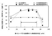
- the figure which shows the relationship between the characteristic of a fuel cell, and the fluororesin content of a 1st cathode gas diffusion layer The figure which shows the relationship between the characteristic of a fuel cell, and the fluororesin content of a 2nd cathode gas diffusion layer.
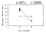
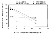
- the figure which shows the relationship between the characteristic of a fuel cell, and the fluororesin content of a 2nd anode gas diffusion layer The figure which shows the relationship between the characteristic of a fuel cell, and the thickness of a 2nd anode gas diffusion layer. The figure which shows the relationship between the characteristic of a fuel cell, and the presence or absence of a 2nd cathode gas diffusion layer. The figure which shows the relationship between the characteristic of a fuel cell, and the presence or absence of a 2nd anode gas diffusion layer. Sectional drawing which shows the principal part of the fuel cell which concerns on Example 2 of this invention. The figure which shows the relationship between the characteristic of a fuel cell, and the fluororesin content of a 4th cathode gas diffusion layer. The figure which shows the relationship between the characteristic of a fuel cell, and various parameters collectively.
- the proton conductive membrane 11 has an oxidant electrode (hereinafter referred to as a cathode) 12 to which an oxidant gas is supplied and a fuel electrode (hereinafter referred to as a cathode) to which fuel is supplied. , Referred to as an anode) 13.
- a cathode 12 oxidant electrode
- a cathode fuel electrode
- anode 13 This configuration is also called a membrane electrode assembly 14.
- the cathode 12 has a structure in which a first cathode gas diffusion layer 15 having a first porous base material containing a fluororesin and a cathode catalyst layer 16 are laminated, and the cathode catalyst layer 16 is a proton conductive membrane 11. Touching.
- the anode 13 has a structure in which a first anode gas diffusion layer 17 having a second porous substrate and an anode catalyst layer 18 are laminated, and the anode catalyst layer 18 is in contact with the proton conductive membrane 11. .
- the first cathode gas diffusion layer 15 has porous carbon paper (first porous substrate) containing, for example, about 30 to 70 wt% of a fluororesin, and is supplied from an oxidant gas supply means (not shown).
- the oxidant gas is supplied to the cathode catalyst layer 16 and functions as a current collector.
- the cathode catalyst layer 16 is a porous layer containing a catalytically active material, a conductive material, and a proton conductive material, such as a porous layer in which carbon particles carrying a Pt catalyst and an ion exchange resin are mixed. It functions to promote the reaction of protons, electrons, and oxygen to produce water.
- the first anode gas diffusion layer 17 has, for example, porous carbon paper (second porous substrate), and supplies fuel supplied from a fuel supply means described later to the anode catalyst layer 18 as a current collector. Plays the function.
- the Anato catalyst layer 18 is a porous layer containing a catalytically active material, a conductive material, and a proton conductive material, such as a porous layer in which carbon particles carrying a Pt—Ru alloy catalyst are mixed with an ion exchange resin. It functions to promote the reaction in which methanol, which is a fuel, reacts with water to produce protons, electrons, and carbon dioxide.
- the proton conductive membrane 11 is a thin film made of a cation exchange resin, for example, a perfluorocarbon sulfonic acid polymer, and functions as a transport path through which protons generated in the anode catalyst layer 18 move to the cathode catalyst layer 16.
- a cation exchange resin for example, a perfluorocarbon sulfonic acid polymer
- a diffusion layer 20 is laminated.
- a third cathode gas diffusion layer 21 having a fourth porous base material with adjusted air permeability and moisture permeability is laminated.
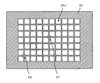
- a heat radiating plate (heat radiating member) 22 having a plurality of through holes 22a is disposed on the third cathode gas diffusion layer 21.
- the cathode conductive layer 19 is, for example, a metal mesh, and evenly contacts the first cathode gas diffusion layer 15 and functions to electrically connect the cathode 12 to the outside.
- the second cathode gas diffusion layer 20 has porous carbon paper (third porous substrate) containing, for example, 5 to 20 wt% fluororesin, and the oxidant gas supplied from the oxidant gas supply means is supplied to the second cathode gas diffusion layer 20. While supplying to 1 cathode gas diffusion layer 15, the discharge
- the third cathode gas diffusion layer 21 is, for example, a polyethylene porous film having a thickness of 0.75 mm, an air permeability of 1.7 seconds / 100 cm 3 , a moisture permeability of 3000 g / m 2 ⁇ 24H, and a Shore hardness of D44. (Fourth porous substrate) functions as a moisture retaining layer impregnated with water produced in the cathode catalyst layer 16.
- the air permeability is measured according to the measuring method specified in JIS P-8117, and the moisture permeability is measured according to the measuring method specified in JIS L-1099A-1.
- Shore hardness is rebound hardness, and is calculated by using a hammer with a diamond hemisphere attached to the tip as an indenter and dividing the bounce height when the hammer is dropped by the original height.
- the heat radiating plate 22 is a metal plate having a high thermal conductivity, for example, a copper plate, takes in the oxidant gas supplied from the oxidant gas supply means through the through hole 22a, and reacts protons, electrons and oxygen in the cathode catalyst layer 16. Thus, the heat of reaction when water is generated is quickly released to the outside.
- a second anode gas diffusion layer 23 having a fifth porous substrate containing a fluororesin is laminated on the first anode gas diffusion layer 17.
- An anode conductive layer 24 is stacked on the second anode gas diffusion layer 23.
- the second anode gas diffusion layer 23 has porous carbon paper (fifth porous substrate) containing, for example, 5 to 20 wt% fluororesin, and is the anode catalyst layer 18 out of the water supplied from the cathode 12.
- porous carbon paper fifth porous substrate
- the water that has passed through the anode catalyst layer 18 without being consumed is stored and held, and the fuel supplied from the fuel supply means described later is uniformly distributed to the anode 13.
- the anode conductive layer 24 is, for example, a metal mesh, and evenly contacts the second anode gas diffusion layer 23 and functions to electrically connect the anode 13 to the outside.
- a rubber O-ring 26 is disposed between the proton conductive membrane 11 and the cathode conductive layer 19, and a seal material is provided between the proton conductive membrane 11 and the anode conductive layer 24.
- the membrane electrode assembly 14 is sealed by disposing a rubber O-ring 27.
- a fuel supply means 30 for supplying fuel (methanol) with the anode conductive layer 24 interposed is disposed.
- the fuel supply means 30 communicates the fuel storage unit 31 that stores liquid fuel, the fuel supply unit 32 that vaporizes the liquid fuel and supplies vaporized fuel to the anode 13, and the fuel storage unit 31 and the fuel supply unit 32. And a flow path 33.
- a pump 34 is provided in the middle of the flow path 33 and delivers liquid fuel from the fuel storage unit 31 to the fuel supply unit 32, and the vaporized fuel vaporized in the fuel supply unit 32 is uniformly supplied to the second anode gas.
- a fuel distribution layer 35 for supplying to the diffusion layer 23.
- the fuel distribution layer 35 is made of a material that does not allow liquid fuel or vaporized fuel to permeate, such as polyethylene terephthalate (PET) resin, polyethylene naphthalate (PEN) resin, or polyimide resin, and has a plurality of through holes 35a for allowing vaporized fuel to pass therethrough.
- PET polyethylene terephthalate
- PEN polyethylene naphthalate
- polyimide resin polyimide resin
- the fuel distribution layer 35 may be, for example, a gas-liquid separation membrane that separates the vaporized component of the liquid fuel from the liquid fuel and transmits the vaporized component to the second anode gas diffusion layer 23 side.
- gas-liquid separation membrane examples include silicone rubber, low density polyethylene (LDPE) thin film, polyvinyl chloride (PVC) thin film, polyethylene terephthalate (PET) thin film, fluororesin (for example, polytetrafluoroethylene (PTFE), tetrafluoroethylene). -Perfluoroalkyl vinyl ether copolymer (PFA) etc.) A microporous film etc. are used.
- the mixed fuel of methanol and water is a methanol aqueous solution or pure methanol having a concentration of 80 Wt% or more.
- pure methanol is used as the fuel, the energy density of the fuel is high, so that the fuel storage unit 31 can be downsized.
- the methanol concentration of the aqueous methanol solution is preferably 80 wt% or more.
- Methanol that has reached the cathode 12 due to the methanol crossover phenomenon directly undergoes a combustion reaction with oxygen in the air at the cathode catalyst layer 16 to generate water and reaction heat.
- reaction heat generated by the methanol crossover phenomenon is effectively utilized to improve the catalytic activity of the cathode 12 and the anode 13 and the proton conductivity of the proton conductive membrane 11.
- the catalytic activity of the cathode 12 and the anode 13 and the proton conductivity of the proton conductive membrane 11 are temperature dependent. By increasing the temperature of the membrane electrode assembly 14, the catalytic activity and proton conductivity can be increased. As a result, the output of the fuel cell 10 can be increased.
- the first anode gas diffusion layer 17 is configured to control the methanol crossover phenomenon within an appropriate range.
- the second cathode gas diffusion layer 20 is configured to have a sufficient water holding capacity.
- the heat radiating plate 22 is configured so that heat radiation from the membrane electrode assembly 14 can be controlled within an appropriate range.
- the fuel cell 10 appropriately maintains the heat radiation from the membrane electrode assembly 14, the amount of water retained in the cathode 12 constituting the membrane electrode assembly 14, and the cathode 12.
- the amount of water supplied to the anode 13 is maintained in an appropriate range within the surface of the membrane electrode assembly 14.
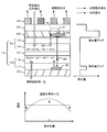
- FIG. 2 is a diagram for explaining the function and effect of each layer of the fuel cell 10.
- the second cathode gas diffusion layer 20 has a lower fluororesin content than the first cathode gas diffusion layer 15. Therefore, the first cathode gas diffusion layer 15 has high water repellency, and the second cathode gas diffusion layer 20 has low water repellency.
- the water vapor 40 generated in the cathode catalyst layer 16 hardly stays in the first cathode gas diffusion layer 15 and is smoothly discharged to the second cathode gas diffusion layer 20.
- the first cathode gas diffusion layer 15 having a high fluororesin content has an effect of suppressing so-called flooding in which water vapor is aggregated in the cathode catalyst layer 16 to inhibit air intake.
- the third cathode gas diffusion layer 21 is capable of holding the water vapor 40 discharged from the cathode catalyst layer 16 while smoothly taking in air by selecting one having adjusted air permeability and moisture permeability. . Most of the water vapor 41 held in the third cathode gas diffusion layer 21 is stored in the second cathode gas diffusion layer 20.
- the second cathode gas diffusion layer 20 functions as a reservoir for the water vapor 41 that is discharged from the first cathode gas diffusion layer 15 and cannot pass through the third cathode gas diffusion layer 21. Since the second cathode gas diffusion layer 20 exhibits high water retention, the water 42 can be smoothly supplied to the anode catalyst layer 18.
- the heat radiating plate 22 by selecting a member having a high thermal conductivity, the heat radiating property is improved, the condensation of the water vapor 41 is promoted, and the temperature distribution can be made uniform in the plane of the membrane electrode assembly 14.
- the temperature distribution is made uniform, the amount of water 43 retained in the second cathode gas diffusion layer 20 increases, and the amount of water 42 supplied to the anode catalyst layer 18 can also increase.
- the second anode gas diffusion layer 23 distributes the fuel flowing in from the fuel distribution layer 35 more uniformly to the first anode gas diffusion layer 17. By uniformly distributing the fuel within the surface of the anode catalyst layer 18, it is possible to prevent a factor in which the temperature distribution in the surface of the membrane electrode assembly 14 becomes uneven.
- the second anode gas diffusion layer 23 can temporarily store the water 44 that could not be consumed by the anode catalyst layer 18 and can return the stored water 44 to the anode catalyst layer 18 again. Can be prepared when there is a shortage of water.
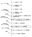
- FIG. 3 is a flowchart showing the manufacturing process of the fuel cell 10. As shown in FIG. 3, first, a membrane electrode assembly 14 in which the proton conductive membrane 11 is sandwiched between the cathode 12 and the anode 13 is formed.
- porous carbon paper 200 mm ⁇ 100 mm, thickness 360 ⁇ m
- the anode catalyst layer paste is applied onto the first anode gas diffusion layer 17 by the doctor blade method and dried to form the anode catalyst layer 18 having a thickness of 150 ⁇ m.
- the doctor blade method is one of methods for processing a powder of a certain material into a plate having a uniform and constant thickness.
- the viscous slurry produced by mixing the raw material powder with solvent, antifoaming agent, resin, etc. is poured into the doctor blade receptacle and extruded through the gap between the flat surface on both edges and the apex of the central ridge.
- a coating film having a constant thickness equal to the step is obtained.
- carbon carrying a cathode catalyst particle (Pt) is obtained by adding a perfluorocarbon sulfonic acid polymer solution as a proton conductive resin and water and methoxypropanol as a dispersion medium to carbon black carrying a cathode catalyst particle (Pt).
- a cathode catalyst layer paste in which black is dispersed is prepared.
- porous carbon paper 200 mm ⁇ 100 mm, thickness 270 ⁇ m, fluororesin content 50 wt%) containing a fluororesin is prepared.
- a cathode catalyst layer paste is applied onto the first cathode gas diffusion layer 15 by a doctor blade method and dried to form a cathode catalyst layer 16 having a thickness of 150 ⁇ m.
- the porous carbon paper In order to contain the fluorocarbon resin in the porous carbon paper, the porous carbon paper is immersed in a solution in which the fluorocarbon resin is dispersed or dissolved, and after natural drying, the fluorocarbon resin is baked at 380 ° C. in an inert atmosphere. By doing. Polytetrafluoroethylene (PTFE) was used as the fluororesin.
- PTFE Polytetrafluoroethylene
- the first anode gas diffusion layer 17 on which the anode catalyst layer 18 is formed and the first cathode gas diffusion layer 15 on which the cathode catalyst layer 16 is formed are cut into rectangles having a length of 40 mm and a width of 30 mm, respectively.
- a perfluorocarbon sulfonic acid polymer membrane (trade name: nafion membrane, manufactured by DuPont) having a thickness of 30 ⁇ m and a water content of 10 to 20 wt% is prepared as the proton conductive membrane 11.
- the proton conductive membrane 11 is sandwiched between the anode catalyst layer 18 and the cathode catalyst layer 16 and hot-pressed, whereby the membrane electrode assembly 14 is obtained.
- porous carbon paper (thickness: 180 ⁇ m, fluorine content: 10 wt%) containing a fluororesin is prepared.
- a second anode gas diffusion layer 23 is laminated on the first anode gas diffusion layer 17.
- a gold foil having a plurality of through holes is prepared as a conductive layer.
- the cathode conductive layer 19 and the anode conductive layer 24 are formed.
- a rubber O-ring 26 is sandwiched between the proton conductive membrane 11 and the cathode conductive layer 19, and a rubber O-ring 27 is sandwiched between the proton conductive membrane 11 and the anode conductive layer 24. Then, a seal is applied around the membrane electrode assembly 14.
- porous carbon paper (thickness: 360 ⁇ m, fluorine resin content: 10 wt%) containing a fluororesin is prepared and laminated on the cathode conductive layer 19.
- the third cathode gas diffusion layer 21 for example, length 44 mm, width 34 mm, thickness 0.75 mm, porosity 26%, air permeability 1.7 seconds / 100 cm 3 , moisture permeability 3000 g / m 2 ⁇ 24 h.
- a polyethylene porous film is prepared and laminated on the second cathode gas diffusion layer 20.
- a 1 mm thick copper plate (thermal conductivity at 370 W / mK at 20 ° C.) in which 70 square through holes 22a each having a side length of 3 mm are uniformly formed is prepared, and the third cathode It is laminated on the gas diffusion layer 21.
- the fluororesin As the first cathode gas diffusion layer 15, the second cathode gas diffusion layer 20, and the second anode gas diffusion layer 23, if porous carbon paper previously containing a target concentration of fluororesin is used, the fluororesin is immersed. The number of processes can be reduced.
- the power generation of the fuel cell 10 was performed by connecting a constant voltage power source to the fuel cell 10 and controlling the current flowing through the fuel cell 10 so that the output voltage of the fuel cell 10 was constant at 0.3V.
- the initial power density P0 when the fuel cell 10 started power generation and the power density P1 after 1000 hours of power generation were measured. From the ratio between the output density P1 and the initial output density P0, the 1000H residual ratio of the output density was determined.
- FIG. 4 is a diagram showing the measurement position of the surface temperature of the third cathode gas diffusion layer 21.
- thermocouple is inserted between the third cathode gas diffusion layer 21 and the second cathode gas diffusion layer 20 through the through hole 22 a of the heat radiating plate 22, and the center of the third cathode gas diffusion layer 21 is inserted.
- the surface temperatures of the part 51 and the peripheral part 52 were measured.
- the output density (mW / cm 2 ) of the fuel cell is obtained by multiplying the current density flowing through the fuel cell (current value per 1 cm 2 area of the power generation unit (mA / cm 2 )) by the output voltage of the fuel cell. It is.
- the area of the power generation unit is an area of a portion where the anode catalyst layer 18 and the cathode catalyst layer 16 are opposed to each other. Here, since the areas of the anode catalyst layer 18 and the cathode catalyst layer 16 are equal and completely opposed to each other, the area of the power generation unit is equal to the areas of these catalyst layers.
- the 1000H remaining rate (hereinafter also simply referred to as the remaining rate) is 95%, and high long-term reliability was obtained.
- the surface temperature Tc of the central part 51 of the third cathode gas diffusion layer 21 and the surface temperature Te of the peripheral part 52 were both 55 ° C., and the temperature distribution of the membrane electrode assembly 14 was uniform.
- the heat dissipation from the membrane electrode assembly 14 is appropriately maintained, the amount of water held in the cathode 12 constituting the membrane electrode assembly 14, and the water supplied from the cathode 12 to the anode 13.
- various parameters of the fuel cell are changed, and the characteristics of the fuel cell (initial value of output density, 1000 H residual rate, membrane The results of examining the temperature of the electrode assembly will be described.
- the parameters of the fuel cell include the thermal conductivity of the heat sink 22, the fluorine resin content of the first cathode gas diffusion layer 15, the fluorine resin content of the second cathode gas diffusion layer 20, and the thickness of the first anode gas diffusion layer 17.
- the fluororesin content of the second anode gas diffusion layer 23 and the thickness of the second anode gas diffusion layer 23 were selected.
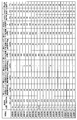
- FIG. 15 collectively shows a series of test conditions and test results obtained by changing various parameters of the fuel cell.
- the series of tests includes 21 examples of Test Examples 1 to 9 and Comparative Examples 1 to 13.
- a test that satisfies the requirements of the fuel cell of this example is referred to as a test example, and a test that does not satisfy the requirement is referred to as a comparative example.
- Test Example 1 This is the test described above.
- the thermal conductivity of the heat sink 22 (copper) is 370 W / mK
- the fluorine resin content of the second cathode gas diffusion layer 20 is 50 wt%
- the fluorine resin content of the second cathode gas diffusion layer 20 is 10 wt%
- the thickness of the anode gas diffusion layer 17 is 360 ⁇ m
- the fluorine resin content of the second anode gas diffusion layer 23 is 10 wt%
- the thickness of the second anode gas diffusion layer 23 is 180 ⁇ m.
- the initial power density P0 was 100%, and the remaining rate was 95%.
- the surface temperature Tc of the central portion 51 of the third cathode gas diffusion layer 21 was 55 ° C.
- the surface temperature Te of the peripheral portion 52 was 55 ° C.
- Test Example 2 The material of the heat radiating plate 22 was changed from copper to aluminum (thermal conductivity 204 W / mK at 20 ° C.). Other conditions are the same as in Test Example 1.
- the initial output density P0 was 95%, and the residual rate was 90%.
- the surface temperature Tc of the central portion 51 of the third cathode gas diffusion layer 21 was 55 ° C., and the surface temperature Te of the peripheral portion 52 was 55 ° C.
- Test Example 3 The fluorine resin content of the first cathode gas diffusion layer 15 was changed from 50 wt% to 70 wt%, and the fluorine resin content of the second cathode gas diffusion layer 20 was changed from 10 wt% to 20 wt%. Other conditions are the same as in Test Example 1.
- the initial power density P0 was 95%, and the remaining rate was 85%.
- the surface temperature Tc of the central portion 51 of the third cathode gas diffusion layer 21 was 55 ° C.
- the surface temperature Te of the peripheral portion 52 was 55 ° C.
- Test Example 4 The fluorine resin content of the first cathode gas diffusion layer 15 was changed from 50 wt% to 30 wt%, and the fluorine resin content of the second cathode gas diffusion layer 20 was changed from 10 wt% to 5 wt%. Other conditions are the same as in Test Example 1.
- the initial power density P0 was 90%, and the residual rate was 95%.
- the surface temperature Tc of the central portion 51 of the third cathode gas diffusion layer 21 was 55 ° C.
- the surface temperature Te of the peripheral portion 52 was 55 ° C.
- Test Example 5 Between the second cathode gas diffusion layer 20 and the third cathode gas diffusion layer 21, a fourth cathode gas diffusion layer 61 having a fluororesin content of 5 wt% described later was disposed. Other conditions are the same as in Test Example 1.
- the initial output density P0 was 102%, and the remaining rate was 96%.
- the surface temperature Tc of the central portion 51 of the third cathode gas diffusion layer 21 was 55 ° C.
- the surface temperature Te of the peripheral portion 52 was 55 ° C.
- Test Example 6 Between the second cathode gas diffusion layer 20 and the cathode conductive layer 19, a fourth cathode gas diffusion layer 61 having a fluorine resin content of 5 wt% was disposed. Other conditions are the same as in Test Example 1.
- the initial output density P0 was 102%, and the remaining rate was 96%.
- the surface temperature Tc of the central portion 51 of the third cathode gas diffusion layer 21 was 55 ° C.
- the surface temperature Te of the peripheral portion 52 was 55 ° C.
- Test Example 7 The fluorine resin content of the first cathode gas diffusion layer 15 is changed from 50 wt% to 60 wt%, the fluorine resin content of the second cathode gas diffusion layer 20 is changed from 10 wt% to 15 wt%, and the fluorine resin of the fourth cathode gas diffusion layer 61 The content was changed from 5 wt% to 10 wt%. Other conditions are the same as in Test Example 1.
- the initial power density P0 was 100%, and the remaining rate was 95%.
- the surface temperature Tc of the central portion 51 of the third cathode gas diffusion layer 21 was 55 ° C.
- the surface temperature Te of the peripheral portion 52 was 55 ° C.
- Test Example 8 The fluororesin content of the second anode gas diffusion layer 23 was changed from 10 wt% to 20 wt%. Other conditions are the same as in Test Example 1.
- the initial output density P0 was 94%, and the residual rate was 93%.
- the surface temperature Tc of the central portion 51 of the third cathode gas diffusion layer 21 was 55 ° C.
- the surface temperature Te of the peripheral portion 52 was 55 ° C.
- Test Example 9 The fluororesin content of the second anode gas diffusion layer 23 was changed from 10 wt% to 5 wt%. Other conditions are the same as in Test Example 1.
- the initial power density P0 was 96%, and the residual rate was 91%.
- the surface temperature Tc of the central portion 51 of the third cathode gas diffusion layer 21 was 55 ° C., and the surface temperature Te of the peripheral portion 52 was 55 ° C.
- the initial power density P0 was 40% and the remaining rate was 40%.
- the surface temperature Tc of the central portion 51 of the third cathode gas diffusion layer 21 was 60 ° C.
- the surface temperature Te of the peripheral portion 52 was 50 ° C.
- the initial power density P0 was 30% and the remaining rate was 10%.
- the surface temperature Tc of the central portion 51 of the third cathode gas diffusion layer 21 was 50 ° C.
- the surface temperature Te of the peripheral portion 52 was 44 ° C.
- the initial power density P0 was 60%, and the remaining rate was 30%.
- the surface temperature Tc of the central portion 51 of the third cathode gas diffusion layer 21 was 53 ° C., and the surface temperature Te of the peripheral portion 52 was 50 ° C.
- the initial power density P0 was 35%, and the remaining rate was 20%.
- the surface temperature Tc of the central portion 51 of the third cathode gas diffusion layer 21 was 50 ° C., and the surface temperature Te of the peripheral portion 52 was 45 ° C.
- the initial power density P0 was 35%, and the remaining rate was 20%.
- the surface temperature Tc of the central portion 51 of the third cathode gas diffusion layer 21 was 51 ° C., and the surface temperature Te of the peripheral portion 52 was 45 ° C.
- the initial power density P0 was 50%, and the remaining rate was 50%.
- the surface temperature Tc of the central portion 51 of the third cathode gas diffusion layer 21 was 60 ° C.
- the surface temperature Te of the peripheral portion 52 was 60 ° C.
- the initial power density P0 was 20% and the remaining rate was 10%.
- the surface temperature Tc of the central portion 51 of the third cathode gas diffusion layer 21 was 56 ° C.
- the surface temperature Te of the peripheral portion 52 was 50 ° C.
- the initial power density P0 was 70%, and the remaining rate was 60%.
- the surface temperature Tc of the central portion 51 of the third cathode gas diffusion layer 21 was 50 ° C., and the surface temperature Te of the peripheral portion 52 was 45 ° C.
- This fuel cell had an initial output density P0 of 70% and a residual rate P1 of 60%.
- the surface temperature Tc of the central portion 51 of the third cathode gas diffusion layer 21 was 55 ° C.
- the surface temperature Te of the peripheral portion 52 was 50 ° C.
- the initial power density P0 was 60%, and the remaining rate P1 was 70%.
- the surface temperature Tc of the central portion 51 of the third cathode gas diffusion layer 21 was 55 ° C., and the surface temperature Te of the peripheral portion 52 was 53 ° C.
- the initial power density P0 was 50%, and the remaining rate was 60%.
- the surface temperature Tc of the central portion 51 of the third cathode gas diffusion layer 21 was 53 ° C.
- the surface temperature Te of the peripheral portion 52 was 51 ° C.
- FIG. 5 to FIG. 12 show the relationship between the parameters of the fuel cell and the characteristics of the fuel cell (initial value of output density, 1000H residual rate, temperature of the membrane electrode assembly) based on each example described above and the result. It explains using.
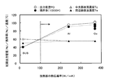
- FIG. 5 is a graph showing the relationship between the thermal conductivity of the heat radiating plate 22 and the characteristics of the fuel cell, in which the results of Test Example 1 to Test Example 9 and Comparative Example 1 are plotted.
- the thermal conductivity was changed by changing the material of the heat radiating plate 22 to copper (Cu), aluminum (Al), or SUS while keeping the shape of the heat radiating plate 22 constant.
- the initial output density P0 is 90 to 102% with respect to the thermal conductivity of the heat sink 22 of 370 W / mK (Cu) and 204 W / mK (Al).
- the residual ratio was as high as 85 to 96%.
- Both the surface temperature Tc of the central portion 51 and the surface temperature Te of the peripheral portion 52 of the third cathode gas diffusion layer 21 were 55 ° C. and were uniform in the plane.
- the heat conductivity of the heat radiating plate 22 is 15 W / mK (SUS)
- the initial output density P0 is 40%
- the residual rate is 40, which are all compared to Test Examples 1 to 9. It decreased to 1/2 or less.
- the surface temperature Tc of the central portion 51 of the third cathode gas diffusion layer 21 was 60 ° C.
- the surface temperature Te of the peripheral portion 52 was 50 ° C., and in-plane nonuniformity occurred.
- the heat conductivity of the heat radiating plate 22 is 100 W / mK or more.
- the cathode 12 is cooled by improving the heat dissipation of the heat radiating plate 22, and the condensation of the water vapor 41 generated by the power generation is promoted accordingly, and the water 42 supplied from the cathode 12 to the anode 13 is increased. It is shown that.
- the upper limit of the thermal conductivity of the heat sink 22 is not particularly defined, but if the thermal conductivity is excessive, the porous material will be clogged by excessively condensed water, so it should be 500 W / mK or less. Is appropriate.
- FIG. 6 is a diagram showing the relationship between the fluorine resin content of the first cathode gas diffusion layer 15 and the characteristics of the fuel cell, in which the results of Test Examples 1 to 9, Comparative Example 2 and Comparative Example 3 are plotted. It is.
- the initial output density P0 is 90 to 102% and the residual ratio is 85 to 96% with respect to the fluororesin content of 30 to 70 wt%. Obtained.
- Both the surface temperature Tc of the central portion 51 and the surface temperature Te of the peripheral portion 52 of the third cathode gas diffusion layer 21 were 55 ° C. and were uniform in the plane.
- the fluororesin content was 85 wt%
- the initial output density P0 was 30%
- the residual rate was 10, both of which were significantly reduced.
- the surface temperature Tc of the central portion 51 of the third cathode gas diffusion layer 21 was 50 ° C.
- the surface temperature Te of the peripheral portion 52 was 44 ° C., resulting in a decrease in surface temperature and in-plane nonuniformity.
- the fluororesin content was 5 wt%
- the initial output density P0 was 60%
- the residual rate was 30%.
- the surface temperature Tc of the central portion 51 of the third cathode gas diffusion layer 21 was 53 ° C.
- the surface temperature Te of the peripheral portion 52 was 50 ° C., resulting in a decrease in surface temperature and in-plane nonuniformity.
- FIG. 7 is a graph showing the relationship between the fluorine resin content of the second cathode gas diffusion layer 20 and the characteristics of the fuel cell, in which the results of Test Example 1 to Test Example 9 and Comparative Example 4 are plotted.
- the initial power density P0 is 90 to 102% and the residual rate is 5% to 20% by weight of the fluorine resin content of the second cathode gas diffusion layer 20.
- a high value of 85 to 96% was obtained.
- Both the surface temperature Tc of the central portion 51 and the surface temperature Te of the peripheral portion 52 of the third cathode gas diffusion layer 21 were 55 ° C. and were uniform in the plane.
- Comparative Example 4 the content of the fluorine resin in the second cathode gas diffusion layer 20 was 70 wt%, the initial output density P0 was 35%, and the remaining rate was significantly reduced to 20%.
- the surface temperature Tc of the central portion 51 of the third cathode gas diffusion layer 21 was 50 ° C., and the surface temperature Te of the peripheral portion 52 was 45 ° C., resulting in a decrease in surface temperature and in-plane nonuniformity.
- FIG. 7 shows that the fluororesin content of the second cathode gas diffusion layer 20 has an appropriate range.
- the content of the fluororesin in the second cathode gas diffusion layer 20 is 5 to 25 wt%.
- FIG. 8 is a diagram showing the relationship between the thickness of the first anode gas diffusion layer 17 and the characteristics of the fuel cell, and plots the results of Test Examples 1 to 9, Comparative Example 6, and Comparative Example 7, respectively.
- the thickness of the first anode gas diffusion layer 17 is 360 ⁇ m
- the initial output density P0 is 90 to 102%
- the remaining rate is as high as 85 to 96%. A value was obtained.
- Both the surface temperature Tc of the central portion 51 and the surface temperature Te of the peripheral portion 52 of the third cathode gas diffusion layer 21 were 55 ° C. and were uniform in the plane.
- the thickness of the first anode gas diffusion layer 17 was 180 ⁇ m, the initial output density P0 was 50%, and the remaining rate was significantly reduced.
- the surface temperature Tc of the central portion 51 of the third cathode gas diffusion layer 21 and the surface temperature Te of the peripheral portion 52 were both 60 ° C., and the temperature increased but no in-plane nonuniformity occurred.
- the thickness of the first anode gas diffusion layer 17 was 540 ⁇ m, the initial output density P0 was 20%, and the remaining rate was significantly reduced to 10%.
- the surface temperature Tc of the central portion 51 of the third cathode gas diffusion layer 21 was 56 ° C., the surface temperature Te of the peripheral portion 52 was 50 ° C., the temperature of the peripheral portion was lowered, and in-plane nonuniformity occurred.
- FIG. 8 shows that the thickness of the first anode gas diffusion layer 17 has an appropriate range. For example, in order to ensure an initial output density of 80% or more and a remaining rate, it is appropriate that the thickness of the first anode gas diffusion layer 17 is 300 to 400 ⁇ m.
- the first anode gas diffusion layer 17 is able to hold the water supplied from the cathode 12 in part by the anode catalyst layer 18 and the water passing through the anode catalyst layer 18 without excess or deficiency. ing. Furthermore, it shows that the amount of methanol crossover can be controlled appropriately.
- FIG. 9 is a diagram showing the relationship between the fluorine resin content of the second anode gas diffusion layer 23 and the characteristics of the fuel cell, and plots the results of Test Examples 1 to 9, Comparative Example 8, and Comparative Example 9, respectively. It is.
- the fluorine resin content of the second anode gas diffusion layer 23 is 5 to 20%
- the initial output density P0 is 90 to 102%
- the residual rate is 85.
- a high value of -96% was obtained.
- Both the surface temperature Tc of the central portion 51 and the surface temperature Te of the peripheral portion 52 of the third cathode gas diffusion layer 21 were 55 ° C. and were uniform in the plane.
- the content of the fluororesin in the second anode gas diffusion layer 23 was 50%, the initial output density P0 was 70%, and the remaining ratio was significantly reduced.
- the surface temperature Tc of the central part 51 of the third cathode gas diffusion layer 21 was 50 ° C., the surface temperature Te of the peripheral part 52 was 45 ° C., the surface temperature was lowered, and in-plane nonuniformity occurred.
- the content of the fluororesin in the second anode gas diffusion layer 23 was 5%, the initial output density P0 was 70%, and the remaining rate was greatly reduced to 60%.
- the surface temperature Tc of the central part 51 of the third cathode gas diffusion layer 21 was 55 ° C.
- the surface temperature Te of the peripheral part 52 was 50 ° C.
- the surface temperature of the peripheral part was lowered, and in-plane nonuniformity occurred.
- the fluororesin content of the second anode gas diffusion layer 23 has an appropriate range. For example, in order to ensure an initial output density and remaining rate of 80% or more, it is appropriate that the content of the fluororesin in the second anode gas diffusion layer 23 is 5 to 20 wt%.
- the second anode gas diffusion layer 23 distributes the fuel flowing in from the fuel distribution layer 35 more uniformly to the first anode gas diffusion layer 17. This shows that the temperature distribution generated in the membrane electrode assembly 14 is made uniform by uniformly distributing the fuel in the plane of the anode catalyst layer 18.
- FIG. 10 is a diagram showing the relationship between the thickness of the second anode gas diffusion layer 23 and the characteristics of the fuel cell, and plots the results of Test Examples 1 to 9, Comparative Example 10, and Comparative Example 11, respectively.
- the initial output density P0 is as high as 90 to 102% and the residual rate is as high as 85 to 96%. A value was obtained.
- Both the surface temperature Tc of the central portion 51 and the surface temperature Te of the peripheral portion 52 of the third cathode gas diffusion layer 21 were 55 ° C. and were uniform in the plane.
- the thickness of the second anode gas diffusion layer 23 was 100 ⁇ m
- the initial output density P0 was 60%
- the remaining rate was 70%.
- the surface temperature Tc of the central portion 51 of the third cathode gas diffusion layer 21 was 55 ° C.
- the surface temperature Te of the peripheral portion 52 was 53 ° C.
- the surface temperature and in-plane uniformity of the peripheral portion 52 were slightly lowered.
- the thickness of the second anode gas diffusion layer 23 was 270 ⁇ m, the initial output density P0 was 50%, and the remaining rate was significantly reduced.
- the surface temperature Tc of the central portion 51 of the third cathode gas diffusion layer 21 was 53 ° C., the surface temperature Te of the peripheral portion 52 was 51 ° C., the surface temperature was lowered, and in-plane nonuniformity occurred.
- FIG. 10 shows that the thickness of the second anode gas diffusion layer 23 has an appropriate range. For example, in order to ensure an initial output density of 60% or more and a remaining rate, it is appropriate that the thickness of the second anode gas diffusion layer 23 is 100 to 200 ⁇ m.
- the second anode gas diffusion layer 23 distributes the fuel flowing from the fuel distribution layer 35 more uniformly to the first anode gas diffusion layer 17, and the temperature distribution generated in the membrane electrode assembly 14 is made uniform. It has been shown.
- FIG. 11 is a diagram showing the relationship between the presence / absence of the second cathode gas diffusion layer 20 and the characteristics of the fuel cell, and plots the results of Test Examples 1 to 9 and Comparative Example 12, respectively.
- the second cathode gas diffusion layer 20 was provided, and the initial output density P0 was 90 to 102%, and the residual ratio was as high as 85 to 96%.
- Both the surface temperature Tc of the central portion 51 and the surface temperature Te of the peripheral portion 52 of the third cathode gas diffusion layer 21 were 55 ° C. and were uniform in the plane.
- the second cathode gas diffusion layer 20 was not provided, the initial output density P0 was 60%, and the residual rate was 70%.
- the surface temperature Tc of the central portion 51 of the third cathode gas diffusion layer 21 was 55 ° C., the surface temperature Te of the peripheral portion 52 was 53 ° C., and the surface temperature and the in-plane uniformity were substantially equal.
- FIG. 12 is a diagram showing the relationship between the presence / absence of the second anode gas diffusion layer 23 and the characteristics of the fuel cell, in which the results of Test Example 1 to Test Example 9 and Comparative Example 13 are plotted.
- the second anode gas diffusion layer 23 is provided, and an initial output density P0 of 90 to 102% and a residual rate of 85 to 96% are obtained. It was. Both the surface temperature Tc of the central portion 51 and the surface temperature Te of the peripheral portion 52 of the third cathode gas diffusion layer 21 were 55 ° C. and were uniform in the plane.
- the second anode gas diffusion layer 23 was not provided, the initial output density P0 was 30%, and the remaining rate was significantly reduced to 20%.
- the surface temperature Tc of the central portion 51 of the third cathode gas diffusion layer 21 is 60 ° C.
- the surface temperature Te of the peripheral portion 52 is 50 ° C.
- the surface temperature of the central portion increases, and the surface temperature of the peripheral portion decreases, In-plane uniformity occurred.
- the fuel cell 10 includes the heat radiating plate 22 having high thermal conductivity and the second cathode gas diffusion layer 20 having a fluorine resin content less than that of the first cathode gas diffusion layer 15. is doing. Further, a second anode gas diffusion layer 23 containing a fluororesin is laminated on the first anode gas diffusion layer 17.
- the fuel cell 10 of this embodiment controls the methanol crossover phenomenon to an appropriate range, thereby effectively utilizing the water generated by the methanol crossover phenomenon to increase the water retention amount, and the methanol crossover phenomenon.
- the catalytic heat and proton conductivity are improved by effectively utilizing the reaction heat generated by the above.
- the heat dissipation from the membrane electrode assembly 14 is appropriately maintained, the amount of water held in the cathode 2 constituting the membrane electrode assembly 14, and the amount of water supplied from the cathode 12 to the anode 13. Can be maintained in an appropriate range in the plane. Therefore, it is possible to obtain a fuel cell that suppresses deterioration of output density and has sufficient reliability.
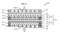
- FIG. 13 is a cross-sectional view showing the main part of the fuel cell.
- the same components as those in the first embodiment are denoted by the same reference numerals, description thereof will be omitted, and different portions will be described.
- This embodiment is different from the first embodiment in that a fourth cathode gas diffusion layer is formed between the second cathode gas diffusion layer and the third cathode gas diffusion layer.
- the fluorine resin content is between the second cathode gas diffusion layer 20 and the third cathode gas diffusion layer 21.
- a fourth cathode gas diffusion layer 61 having a content less than that of the fluororesin is formed.
- the fourth cathode gas diffusion layer 61 is a porous layer having particulate carbon and a fluororesin.
- the fluorine resin content of the fourth cathode gas diffusion layer 61 is smaller than the fluorine resin content ( ⁇ 20 wt%) of the second cathode gas diffusion layer 20, and is set to 5 wt%, for example.
- the fourth cathode gas diffusion layer 61 is a layer that has a fine mesh and is easy to contain water and has a low water repellency because it has a low fluororesin content.
- the fourth cathode gas diffusion layer 61 is provided to further increase the water retention amount on the cathode 12 side.
- FIG. 14 is a graph showing the relationship between the fluorine resin content of the fourth cathode gas diffusion layer 61 and the characteristics of the fuel cell, and plots the results of Test Example 5 to Test Example 7 and Comparative Example 5, respectively.
- the initial output density P0 was significantly reduced to 35% and the residual rate 20%.
- the surface temperature Tc of the central portion 51 of the third cathode gas diffusion layer 21 was 51 ° C.
- the surface temperature Te of the peripheral portion 52 was 45 ° C., resulting in a decrease in surface temperature and nonuniformity.
- FIG. 14 shows that the fluororesin content of the fourth cathode gas diffusion layer 61 has an appropriate range. For example, in order to ensure an initial output density and a remaining rate of 80% or more, it is appropriate that the fluorine resin content of the fourth cathode gas diffusion layer 61 is smaller than the fluorine resin content of the second cathode gas diffusion layer 20. It is.
- a method for forming the fourth cathode gas diffusion layer 61 will be described. First, a paste in which particulate carbon is dispersed in a solution in which a fluororesin is dispersed or dissolved is prepared. Next, this paste is applied onto the second cathode gas diffusion layer 20 and dried. Thereafter, the fluororesin is baked under an inert atmosphere.
- the fourth cathode gas diffusion layer 61 having the particulate carbon and the fluororesin is laminated on the second cathode gas diffusion layer 20.
- the particulate carbon is, for example, carbon black
- the fluororesin is, for example, polytetrafluoroethylene (PTFE), tetrafluoroethylene-hexafluoropropylene copolymer resin (FEP), tetrafluoroethylene perfluoroalkyl vinyl ether copolymer. Resin (PFA).
- the present invention is not limited to this, and any material having sufficient conductivity and stability can be used.
- the fourth cathode gas diffusion layer 61 having a fine mesh and low water repellency is provided between the second cathode gas diffusion layer 20 and the third cathode gas diffusion layer 21. Is formed.
- the cathode conductive layer 19 and the second cathode gas diffusion layer 20 are described. You may form between.
- the second cathode gas diffusion layer 20 on which the fourth cathode gas diffusion layer 61 is laminated may be reversed to bring the fourth cathode gas diffusion layer 61 into contact with the cathode conductive layer 19. In either case, equivalent characteristics are obtained.
Landscapes
- Chemical & Material Sciences (AREA)
- Chemical Kinetics & Catalysis (AREA)
- Electrochemistry (AREA)
- General Chemical & Material Sciences (AREA)
- Life Sciences & Earth Sciences (AREA)
- Engineering & Computer Science (AREA)
- Manufacturing & Machinery (AREA)
- Sustainable Development (AREA)
- Sustainable Energy (AREA)
- Composite Materials (AREA)
- Fuel Cell (AREA)
- Inert Electrodes (AREA)
Abstract
セル電圧の劣化を抑制し、十分な信頼性を有する燃料電池を提供する。 カソード触媒層16と、カソード触媒層16に積層され、フッ素樹脂を含有する第1カソードガス拡散層15とを備え、酸化剤ガスが供給されるカソード12と、アノード触媒層18と、アノード触媒層18に積層されたアノードガス拡散層17、23とを備え、燃料が供給されるアノード13と、カソード12のカソード触媒層16とアノード13のアノード触媒層18とに挟持されたプロトン伝導性膜11と、第1カソードガス拡散層15に積層され、フッ素樹脂含有量が第1カソードガス拡散層15より少ない第2カソードガス拡散層20と、第2カソードガス拡散層20に積層され、カソード12で生成した水を含浸する第3カソードガス拡散層21と、第3カソードガス拡散層21に接触した放熱部材22と、を具備する。
Description
本発明は、燃料電池に関する。
従来、燃料電池として、カソード触媒層において生成した水を、プロトン伝導性膜を通してアノード触媒層に供給することによって、出力密度などの電池特性を向上させたものが知られている(例えば、特許文献1参照。)。
この燃料電池では、液体燃料を気化させた気化燃料をアノードに供給し、アノード触媒層において気化燃料と反応する水を確保するために、空気導入口を有する表面層とカソードとの間に、カソード触媒層において生成した水を含浸して蒸散を抑制する保湿層が設けられている。
これにより、カソード触媒層の水分保持量がアノード触媒層の水分保持量よりも多い状態を作り出し、カソード触媒層において生成した水がプロトン伝導性膜を通してアノード触媒層へ拡散するのを促進して、出力密度の向上を図っている。
然しながら、この燃料電池では、保湿層の保水能力および保水量に限界があり、カソードからアノードに水を安定して供給するのが難しいので、初期特性においては高い出力密度が得られても、長期特性においては十分な信頼性が得られないという問題がある。
出力密度を長期間にわたって維持するためには、カソードからの放熱を適切に確保し、カソードに保持される水の量とカソードからアノードに供給される水の量とのバランスを適切に維持していくことが求められる。然し、この点に関しては何らの開示も、示唆も見られない。
本発明は、出力密度の劣化を抑制し、十分な信頼性を有する燃料電池を提供する。
本発明の一態様の燃料電池は、カソード触媒層と、前記カソード触媒層に積層され、フッ素樹脂を含有する第1カソードガス拡散層とを備え、酸化剤ガスが供給されるカソードと、アノード触媒層と、前記アノード触媒層に積層されたアノードガス拡散層とを備え、燃料が供給されるアノードと、前記カソードの前記カソード触媒層と前記アノードの前記アノード触媒層とに挟持されたプロトン伝導性膜と、前記第1カソードガス拡散層に積層され、フッ素樹脂含有量が前記第1カソードガス拡散層より少ない第2カソードガス拡散層と、前記第2カソードガス拡散層に積層され、前記カソードで生成した水を含浸する第3カソードガス拡散層と、前記第3カソードガス拡散層に接触した放熱部材と、を具備することを特徴としている。
本発明によれば、出力密度の劣化を抑制し、十分な信頼性を有する燃料電池が得られる。
以下、本発明の実施例について図面を参照しながら説明する。
図1に示すように、本実施例の燃料電池10は、プロトン伝導性膜11を酸化剤ガスが供給される酸化剤極(以下、カソードという)12と、燃料が供給される燃料極(以下、アノードという)13とで挟持した構成となっている。この構成は、膜電極接合体14とも呼ばれている。
カソード12は、フッ素樹脂を含有する第1多孔質基材を有する第1カソードガス拡散層15と、カソード触媒層16とが積層された構造を有し、カソード触媒層16がプロトン伝導性膜11に接触している。
アノード13は、第2多孔質基材を有する第1アノードガス拡散層17と、アノード触媒層18とが積層された構造を有し、アノード触媒層18がプロトン伝導性膜11に接触している。
第1カソードガス拡散層15は、例えば30~70wt%程度のフッ素樹脂を含有する多孔質カーボンペーパ(第1多孔質基材)を有し、酸化剤ガス供給手段(図示せず)から供給された酸化剤ガスをカソード触媒層16へ供給するとともに、集電体としての機能を果たしている。
カソード触媒層16は、触媒活性物質と、導電性物質と、プロトン伝導物質とを含有する多孔質層、例えばPt触媒が担持されたカーボン粒子とイオン交換樹脂とを混合した多孔質層であり、プロトン、電子および酸素が反応して水が生成される反応を促進する機能を果たしている。
第1アノードガス拡散層17は、例えば多孔質カーボンペーパ(第2多孔質基材)を有し、後述する燃料供給手段から供給された燃料をアノード触媒層18へ供給するとともに、集電体としての機能を果たしている。
アノート触媒層18は、触媒活性物質と、導電性物質と、プロトン伝導物質とを含有する多孔質層、例えばPt-Ru合金触媒が担持されたカーボン粒子とイオン交換樹脂とを混合した多孔質層であり、燃料であるメタノールと水が反応してプロトン、電子および二酸化炭素が生成される反応を促進する機能を果たしている。
プロトン伝導性膜11は、陽イオン交換樹脂、例えばパーフルオロカーボンスルホン酸ポリマーからなる薄膜で、アノード触媒層18で生成したプロトンがカソード触媒層16へ移動する輸送路としての機能を果たしている。
更に、カソード12側には、第1カソードガス拡散層15上にカソード導電層19を挟んで第1カソードガス拡散層15よりフッ素樹脂含有量が少ない第3多孔質基材を有する第2カソードガス拡散層20が積層されている。
第2カソードガス拡散層20上には、透気度および透湿度が調整された第4多孔質基材を有する第3カソードガス拡散層21が積層されている。第3カソードガス拡散層21上には、複数の貫通孔22aを有する放熱板(放熱部材)22が配置されている。
カソード導電層19は、例えば金属メッシュで、第1カソードガス拡散層15とむらなく接触してカソード12を外部に電気的に接続する機能を果たしている。
第2カソードガス拡散層20は、例えば5~20wt%のフッ素樹脂を含有する多孔質カーボンペーパ(第3多孔質基材)を有し、酸化剤ガス供給手段から供給された酸化剤ガスを第1カソードガス拡散層15へ供給するとともに、カソード触媒層16で生成した水の排出を促進し、第1カソードガス拡散層15に水が滞留しにくくする機能を果たしている。
第3カソードガス拡散層21は、例えば厚さが0.75mm、透気度が1.7秒/100cm3、透湿度が3000g/m2・24H、およびショア硬度がD44のポリエチレン製多孔質フィルム(第4多孔質基材)で、カソード触媒層16で生成した水を含浸する保湿層としての機能を果たしている。
なお、透気度はJIS P-8117に規定の測定方法、透湿度はJIS L-1099 A-1に規定の測定方法によるものである。ショア硬度とは反発硬さであり、圧子として先端にダイヤモンド半球を取り付けたハンマーを用い、ハンマーを落とした時の跳ね返り高さを元の高さで割って算出される。
放熱板22は、熱伝導率の高い金属板、例えば銅板であり、貫通孔22aを通して酸化剤ガス供給手段から供給された酸化剤ガスを取り込むとともに、カソード触媒層16でプロトン、電子および酸素が反応して水が生成する際の反応熱を外部に速やかに放熱する機能を果たしている。
一方、アノード13側には、第1アノードガス拡散層17上にフッ素樹脂を含有する第5多孔質基材を有する第2アノードガス拡散層23が積層されている。第2アノードガス拡散層23上には、アノード導電層24が積層されている。
第2アノードガス拡散層23は、例えば5~20wt%のフッ素樹脂を含有する多孔質カーボンペーパ(第5多孔質基材)を有し、カソード12から供給された水のうちアノード触媒層18で消費されずにアノード触媒層18を通過した水を貯留して保持するとともに、後述する燃料供給手段から供給された燃料を均一にアノード13に分配する機能を果たしている。
アノード導電層24は、例えば金属メッシュで、第2アノードガス拡散層23とむらなく接触してアノード13を外部に電気的に接続する機能を果たしている。
なお、プロトン伝導性膜11とカソード導電層19との間にはシール材として、例えばゴム製のOリング26を配置し、プロトン伝導性膜11とアノード導電層24との間にはシール材として、例えばゴム製のOリング27を配置することにより、膜電極接合体14にシールが施されている。
第2アノードガス拡散層23上には、アノード導電層24を挟んで燃料(メタノール)を供給する燃料供給手段30が配置されている。
燃料供給手段30は、液体燃料を貯留する燃料収容部31と、液体燃料を気化させてアノード13に気化燃料を供給する燃料供給部32と、燃料収容部31と燃料供給部32とを連通する流路33とを有している。
更に、流路33の途中に介在し、燃料収容部31から燃料供給部32に液体燃料を送出するポンプ34と、燃料供給部32内で液体燃料が気化した気化燃料を均一に第2アノードガス拡散層23に供給するための燃料分配層35とを有している。
燃料分配層35は、液体燃料や気化燃料を透過させない材料、例えばポリエチレンテレフタレート(PET)樹脂、ポリエチレンナフタレート(PEN)樹脂、ポリイミド系樹脂で、気化燃料を通過させるための複数の貫通孔35aを有している。
また、燃料分配層35は、例えば、液体燃料の気化成分と液体燃料とを分離し、その気化成分を第2アノードガス拡散層23側へ透過させる気液分離膜であってもよい。気液分離膜には、例えば、シリコーンゴム、低密度ポリエチレン(LDPE)薄膜、ポリ塩化ビニル(PVC)薄膜、ポリエチレンテレフタレート(PET)薄膜、フッ素樹脂(たとえばポリテトラフルオロエチレン(PTFE)、テトラフルオロエチレン・パーフルオロアルキルビニルエーテル共重合体(PFA)など)微多孔膜などが用いられる。
燃料電池10は、アノード13に燃料供給手段30から、メタノールと水の混合燃料が供給され、カソード12に酸化剤ガス供給手段から空気(酸素)が供給されると、触媒により次式に示す反応が促進される。アノード13とカソード12とを配線で接続することにより、外部に電力が取り出せるため、ダイレクトメタノール型燃料電池(DMFC)とも呼ばれる。
アノード:CH3OH+H2O → CO2+6H++6e- (1)
カソード:6H++(3/2)O2+6e- → 3H2O (2)
メタノールと水の混合燃料とは、濃度80Wt%以上のメタノール水溶液または純メタノールのことである。燃料に純メタノールを用いると、燃料のエネルギー密度が高いので、燃料収容部31を小型化することができる。
カソード:6H++(3/2)O2+6e- → 3H2O (2)
メタノールと水の混合燃料とは、濃度80Wt%以上のメタノール水溶液または純メタノールのことである。燃料に純メタノールを用いると、燃料のエネルギー密度が高いので、燃料収容部31を小型化することができる。
一方、燃料にメタノール水溶液を用いると、燃料と共に供給される水も式1の反応に使用される。その結果、アノードに供給される水が十分に確保されるので、安定した発電を長期に渡って行うことができる。
但し、メタノール水溶液は、水の含有量が多過ぎると、気化しづらくなるので、アノードに供給されるメタノールが減少し、発電特性が低下する。また、燃料収納部31が大型化する。従って、メタノール水溶液のメタノール濃度は、80wt%以上とすることが好ましい。
メタノール水溶液のメタノール濃度が高くなると、アノード13で消費されなかったメタノールの一部がプロトン伝導性膜11を通過してカソード12に至るメタノールクロスオーバー現象が顕著に生じるようになる。
メタノールクロスオーバー現象により、カソード12に到達したメタノールは、カソード触媒層16で空気中の酸素と直接燃焼反応し、水および反応熱が生じる。
本実施例では、メタノールクロスオーバー現象を適正な範囲に制御することで、メタノールクロスオーバー現象により生じる水を有効に活用して保水量の増加を図っている。
更に本実施例では、メタノールクロスオーバー現象により生じる反応熱を有効に活用してカソード12およびアノード13の触媒活性およびプロトン伝導性膜11のプロトン伝導性の向上を図っている。
カソード12およびアノード13の触媒活性およびプロトン伝導性膜11のプロトン伝導性は温度依存性を有している。膜電極接合体14の温度を高めることにより、触媒活性およびプロトン伝導性を高くすることができる。その結果、燃料電池10の出力を高めることが可能である。
そのために、第1アノードガス拡散層17は、メタノールクロスオーバー現象を適正な範囲に制御できるように構成されている。第2カソードガス拡散層20は、十分な保水能力を有するように構成されている。放熱板22は、膜電極接合体14からの放熱を適正な範囲に制御できるように構成されている。
これにより、本実施例の燃料電池10は、膜電極接合体14からの放熱が適切に維持されるとともに、膜電極接合体14を構成するカソード12中に保持される水の量と、カソード12からアノード13に供給される水の量とが、膜電極接合体14の面内で適切な範囲に維持されるように構成されている。
図2は燃料電池10の各層の作用効果を説明するための図である。図2に示すように、第2カソードガス拡散層20は、第1カソードガス拡散層15よりフッ素樹脂含有量が少ない。そのため、第1カソードガス拡散層15は撥水性が高く、第2カソードガス拡散層20は撥水性が低くなる。その結果、カソード触媒層16で生成した水蒸気40は、第1カソードガス拡散層15に留まりにくく、第2カソードガス拡散層20へ円滑に排出される。
フッ素樹脂含有量の多い第1カソードガス拡散層15は、カソード触媒層16で水蒸気が凝集し、空気の取り込みを阻害する、いわゆるフラッディングを抑制する効果がある。
第3カソードガス拡散層21は、透気度、透湿度を調整したものを選択することにより、空気の取り込みを円滑に行いながら、カソード触媒層16から排出される水蒸気40を保持することができる。第3カソードガス拡散層21で保持された水蒸気41の多くは、第2カソードガス拡散層20にて貯留されることになる。
すなわち、第2カソードガス拡散層20は、第1カソードガス拡散層15から排出され、第3カソードガス拡散層21を通過できなかった水蒸気41の溜り場としての機能がある。第2カソードガス拡散層20が高い保水性を発揮することで、アノード触媒層18へ水42を円滑に供給できる。
放熱板22は、熱伝導率が高い部材を選択することで、放熱性が向上し、水蒸気41の凝縮が促進され、膜電極接合体14の面内で温度分布を均一化することができる。温度分布が均一化されると、第2カソードガス拡散層20において保持される水43の量も多くなり、アノード触媒層18に供給される水42の量も増量することができる。
第2アノードガス拡散層23は、燃料分配層35より流入する燃料をさらに均一に第1アノードガス拡散層17へ分配する。アノード触媒層18の面内で燃料を均一に分配することで膜電極接合体14の面内の温度分布が不均一化する要因を未然に防止することができる。
第2アノードガス拡散層23は、アノード触媒層18で消費しきれなかった水44を一時貯留し、貯留された水44を再びアノード触媒層18に戻すことができるので、アノード触媒層18に必要な水が不足した場合に備えることができる。
上記構成の燃料電池10では、膜電極接合体14からの放熱が適切に維持されるとともに、膜電極接合体14を構成するカソード12中に保持される水の量と、カソード12からアノード13に供給される水の量とが、膜電極接合体14の面内で適切な範囲に維持されるので、長時間にわたって高い出力を安定して維持することができる。
図3は燃料電池10の製造工程を示すフローチャートである。図3に示すように、始に、カソード12、アノード13でプロトン伝導性膜11を挟持した膜電極接合体14を形成する。
アノード用触媒粒子(Pt:Ru=1:1、原子比組成)を担持したカーボンブラックに、プロトン伝導性樹脂としてパーフルオロカーボンスルホン酸ポリマー溶液と、分散媒として水およびメトキシプロパノールを添加して、アノード用触媒粒子を担持したカーボンブラックを分散させたアノード触媒層用ペーストを調製する。
第1アノードガス拡散層17として、多孔質カーボンペーパ(200mm×100mm、厚さ360μm)を用意する。第1アノードガス拡散層17上にアノード触媒層用ペーストをドクターブレード法により塗布し、乾燥させることにより、厚さ150μmのアノード触媒層18を形成する。
ドクターブレード法とは、ある材料の粉を均質で一定の厚みを有する板に加工する方法の一つである。原料粉末と溶媒、消泡剤、樹脂などを混合して生成した粘り気のあるスラリーをドクターブレードの受け口に流し込み、両縁の平坦面と中央の山型の凸部の頂点との隙間から押出すと、段差に等しい一定の厚みを有する塗膜が得られるものである。
同様に、カソード用触媒粒子(Pt)を担持したカーボンブラックに、プロトン伝導性樹脂としてパーフルオロカーボンスルホン酸ポリマー溶液と、分散媒として水およびメトキシプロパノールを添加して、カソード用触媒粒子を担持したカーボンブラックを分散させたカソード触媒層用ペーストを調製する。
第1カソードガス拡散層15として、フッ素樹脂を含有する多孔質カーボンペーパ(200mm×100mm、厚さ270μm、フッ素樹脂含有量50wt%)を用意する。第1カソードガス拡散層15上にカソード触媒層用ペーストをドクターブレード法により塗布し、乾燥させることにより、厚さ150μmのカソード触媒層16を形成する。
なお、多孔質カーボンペーパにフッ素樹脂を含有させるには、フッ素樹脂が分散または溶解した溶液に多孔質カーボンペーパを浸漬し、自然乾燥の後、不活性雰囲気下、380℃でフッ素樹脂を焼付けることにより行う。フッ素樹脂には、ポリテトラフルオロエチレン(PTFE)を使用した。
アノード触媒層18を形成した第1アノードガス拡散層17、およびカソード触媒層16を形成した第1カソードガス拡散層15は、それぞれ長さ40mm、幅30mmの長方形に切り出す。
次に、プロトン伝導性膜11として、厚さ30μm、含水率が10~20wt%のパーフルオロカーボンスルホン酸ポリマー膜(商品名:nafion膜、デュポン社製)を用意する。プロトン伝導性膜11をアノード触媒層18とカソード触媒層16とで挟み、ホットプレスを施すことにより、膜電極接合体14が得られる。
次に、第2アノードガス拡散層23として、フッ素樹脂を含有する多孔質カーボンペーパ(厚さ180μm、フッ素含有量10wt%)を用意する。第1アノードガス拡散層17に第2アノードガス拡散層23を積層する。
次に、導電層として、複数の貫通孔を有する金箔を用意する。この金箔をそれぞれ第1カソードガス拡散層15および第2アノードガス拡散層23に積層することにより、カソード導電層19およびアノード導電層24を形成する。
次に、プロトン伝導性膜11とカソード導電層19との間にゴム製のOリング26を挟持し、プロトン伝導性膜11とアノード導電層24との間にゴム製のOリング27を挟持し、膜電極接合体14の周りにシールを施す。
次に、第2カソードガス拡散層20として、フッ素樹脂を含有する多孔質カーボンペーパ(厚さ360μm、フッ素樹脂含有量10wt%)を用意し、カソード導電層19に積層する。
次に、第3カソードガス拡散層21として、例えば長さ44mm、幅34mm、厚さ0.75mm、気孔率26%、透気度1.7秒/100cm3、透湿度3000g/m2・24hのポリエチレン製多孔質フィルムを用意し、第2カソードガス拡散層20に積層する。
次に、放熱板22として、一辺の長さが3mmの正方形の貫通孔22aを均等に70個形成した厚さ1mmの銅板(20℃における熱伝導率370W/mK)を用意し、第3カソードガス拡散層21に積層する。
第3カソードガス拡散層21と放熱板22との間に隙間があると、第3カソードガス拡散層21から放熱板22への熱伝導が円滑に行なわれなくなるため、第3カソードガス拡散層21と放熱板22とは出来るだけ密着させることが望ましい。
第1カソードガス拡散層15、第2カソードガス拡散層20、第2アノードガス拡散層23として、それぞれ予め目的の濃度のフッ素樹脂を含有させた多孔質カーボンペーパを用いれば、フッ素樹脂を浸漬する工程を削減することができる。
次に、上述した燃料電池10に、室温25℃、相対湿度50%の環境下で、純度99.9%wtの純メタノールを供給して、燃料電池10の発電特性を調べた結果について説明する。
燃料電池10の発電は、燃料電池10に定電圧電源を接続して、燃料電池10の出力電圧が0.3Vで一定になるように、燃料電池10に流れる電流を制御しながら行った。
燃料電池10の発電特性として、燃料電池10が発電を開始した時の初期出力密度P0および1000時間発電を行なった後の出力密度P1を測定した。出力密度P1と初期出力密度P0との比から、出力密度の1000H残存率を求めた。
同時に、燃料電池10が発電を行なっているときの第3カソードガス拡散層21の表面温度を測定し、温度分布の面内均一性を調べた。図4は第3カソードガス拡散層21の表面温度の測定位置を示す図である。
図4に示すように、放熱板22の貫通孔22aを通して、第3カソードガス拡散層21と第2カソードガス拡散層20との間に熱電対を挿入し、第3カソードガス拡散層21の中央部51および周辺部52の表面温度を測定した。
なお、燃料電池の出力密度(mW/cm2)とは、燃料電池に流れる電流密度(発電部の面積1cm2当りの電流値(mA/cm2))に燃料電池の出力電圧を乗じたものである。発電部の面積とは、アノード触媒層18とカソード触媒層16とが対向している部分の面積である。ここでは、アノード触媒層18とカソード触媒層16の面積が等しく、かつ完全に対向しているので、発電部の面積はこれらの触媒層の面積に等しい。
測定の結果、燃料電池10の初期出力密度P0を100%として、1000H残存率(以後、単に残存率ともいう)は95%であり、高い長期信頼性が得られた。第3カソードガス拡散層21の中央部51の表面温度Tc、および周辺部52の表面温度Teは、いずれも55℃であり、膜電極接合体14の温度分布は均一であった。
次に、膜電極接合体14からの放熱が適切に維持されるとともに、膜電極接合体14を構成するカソード12中に保持される水の量と、カソード12からアノード13に供給される水の量とが、膜電極接合体14の面内で適切に維持される範囲を確かめるために、燃料電池のパラメータを種々変更して、燃料電池の特性(出力密度の初期値、1000H残存率、膜電極接合体の温度)を調べた結果について説明する。
燃料電池のパラメータとしては、放熱板22の熱伝導率、第1カソードガス拡散層15のフッ素樹脂含有量、第2カソードガス拡散層20のフッ素樹脂含有量、第1アノードガス拡散層17の厚さ、第2アノードガス拡散層23のフッ素樹脂含有量、第2アノードガス拡散層23の厚さを選択した。
図15は、燃料電池のパラメータを種々変更した一連の試験条件および試験結果をまとめて示したものである。一連の試験には、試験例1乃至試験例9と、比較例1乃至比較例13との21例が含まれている。ここでは、本実施例の燃料電池の要件を満たす試験を試験例と称し、満たさない試験を比較例と称している。各例およびその結果について説明する。
(試験例1)
上述した試験である。放熱板22(銅)の熱伝導率質が370W/mK、第2カソードガス拡散層20のフッ素樹脂含有量が50wt%、第2カソードガス拡散層20のフッ素樹脂含有量が10wt%、第1アノードガス拡散層17の厚さが360μm、第2アノードガス拡散層23のフッ素樹脂含有量が10wt%、第2アノードガス拡散層23の厚さが180μmである。
上述した試験である。放熱板22(銅)の熱伝導率質が370W/mK、第2カソードガス拡散層20のフッ素樹脂含有量が50wt%、第2カソードガス拡散層20のフッ素樹脂含有量が10wt%、第1アノードガス拡散層17の厚さが360μm、第2アノードガス拡散層23のフッ素樹脂含有量が10wt%、第2アノードガス拡散層23の厚さが180μmである。
この燃料電池では、初期出力密度P0が100%、残存率が95%であった。第3カソードガス拡散層21の中央部51の表面温度Tcが55℃、周辺部52の表面温度Teが55℃であった。
(試験例2)
放熱板22の材質を銅からアルミニウム(20℃における熱伝導率204W/mK)に変更した。その他の条件は試験例1と同様である。
放熱板22の材質を銅からアルミニウム(20℃における熱伝導率204W/mK)に変更した。その他の条件は試験例1と同様である。
この燃料電池では、初期出力密度P0が95%、残存率が90%であった。第3カソードガス拡散層21の中央部51の表面温度Tcが55℃、周辺部52の表面温度Teが55℃であった。
(試験例3)
第1カソードガス拡散層15のフッ素樹脂含有量を50wt%から70wt%に、第2カソードガス拡散層20のフッ素樹脂含有量を10wt%から20wt%に変更した。その他の条件は試験例1と同様である。
第1カソードガス拡散層15のフッ素樹脂含有量を50wt%から70wt%に、第2カソードガス拡散層20のフッ素樹脂含有量を10wt%から20wt%に変更した。その他の条件は試験例1と同様である。
この燃料電池では、初期出力密度P0が95%、残存率が85%であった。第3カソードガス拡散層21の中央部51の表面温度Tcが55℃、周辺部52の表面温度Teが55℃であった。
(試験例4)
第1カソードガス拡散層15のフッ素樹脂含有量を50wt%から30wt%に、第2カソードガス拡散層20のフッ素樹脂含有量を10wt%から5wt%に変更した。その他の条件は試験例1と同様である。
第1カソードガス拡散層15のフッ素樹脂含有量を50wt%から30wt%に、第2カソードガス拡散層20のフッ素樹脂含有量を10wt%から5wt%に変更した。その他の条件は試験例1と同様である。
この燃料電池では、初期出力密度P0が90%、残存率が95%であった。第3カソードガス拡散層21の中央部51の表面温度Tcが55℃、周辺部52の表面温度Teが55℃であった。
(試験例5)
第2カソードガス拡散層20と第3カソードガス拡散層21との間に、後述するフッ素樹脂含有量が5wt%の第4カソードガス拡散層61を配置した。その他の条件は試験例1と同様である。
第2カソードガス拡散層20と第3カソードガス拡散層21との間に、後述するフッ素樹脂含有量が5wt%の第4カソードガス拡散層61を配置した。その他の条件は試験例1と同様である。
この燃料電池では、初期出力密度P0が102%、残存率が96%であった。第3カソードガス拡散層21の中央部51の表面温度Tcが55℃、周辺部52の表面温度Teが55℃であった。
(試験例6)
第2カソードガス拡散層20とカソード導電層19との間に、フッ素樹脂含有量が5wt%の第4カソードガス拡散層61を配置した。その他の条件は試験例1と同様である。
第2カソードガス拡散層20とカソード導電層19との間に、フッ素樹脂含有量が5wt%の第4カソードガス拡散層61を配置した。その他の条件は試験例1と同様である。
この燃料電池では、初期出力密度P0が102%、残存率が96%であった。第3カソードガス拡散層21の中央部51の表面温度Tcが55℃、周辺部52の表面温度Teが55℃であった。
(試験例7)
第1カソードガス拡散層15のフッ素樹脂含有量を50wt%から60wt%に、第2カソードガス拡散層20のフッ素樹脂含有量を10wt%から15wt%に、第4カソードガス拡散層61のフッ素樹脂含有量を5wt%から10wt%に変更した。その他の条件は試験例1と同様である。
第1カソードガス拡散層15のフッ素樹脂含有量を50wt%から60wt%に、第2カソードガス拡散層20のフッ素樹脂含有量を10wt%から15wt%に、第4カソードガス拡散層61のフッ素樹脂含有量を5wt%から10wt%に変更した。その他の条件は試験例1と同様である。
この燃料電池では、初期出力密度P0が100%、残存率が95%であった。第3カソードガス拡散層21の中央部51の表面温度Tcが55℃、周辺部52の表面温度Teが55℃であった。
(試験例8)
第2アノードガス拡散層23のフッ素樹脂含有量を10wt%から20wt%に変更した。その他の条件は試験例1と同様である。
第2アノードガス拡散層23のフッ素樹脂含有量を10wt%から20wt%に変更した。その他の条件は試験例1と同様である。
この燃料電池では、初期出力密度P0が94%、残存率が93%であった。第3カソードガス拡散層21の中央部51の表面温度Tcが55℃、周辺部52の表面温度Teが55℃であった。
(試験例9)
第2アノードガス拡散層23のフッ素樹脂含有量を10wt%から5wt%に変更した。その他の条件は試験例1と同様である。
第2アノードガス拡散層23のフッ素樹脂含有量を10wt%から5wt%に変更した。その他の条件は試験例1と同様である。
この燃料電池では、初期出力密度P0が96%、残存率が91%であった。第3カソードガス拡散層21の中央部51の表面温度Tcが55℃、周辺部52の表面温度Teが55℃であった。
(比較例1)
放熱板22の材質を銅からステンレス(SUS304、20℃における熱伝導率15W/mK)に変更した。その他の条件は試験例1と同様である。
放熱板22の材質を銅からステンレス(SUS304、20℃における熱伝導率15W/mK)に変更した。その他の条件は試験例1と同様である。
この燃料電池では、初期出力密度P0が40%、残存率が40%であった。第3カソードガス拡散層21の中央部51の表面温度Tcが60℃、周辺部52の表面温度Teが50℃であった。
(比較例2)
第1カソードガス拡散層15のフッ素樹脂含有量を50wt%から85wt%に変更した。その他の条件は試験例1と同様である。
第1カソードガス拡散層15のフッ素樹脂含有量を50wt%から85wt%に変更した。その他の条件は試験例1と同様である。
この燃料電池では、初期出力密度P0が30%、残存率が10%であった。第3カソードガス拡散層21の中央部51の表面温度Tcが50℃、周辺部52の表面温度Teが44℃であった。
(比較例3)
第1カソードガス拡散層15のフッ素樹脂含有量を50wt%から5wt%に変更した。その他の条件は試験例1と同様である。
第1カソードガス拡散層15のフッ素樹脂含有量を50wt%から5wt%に変更した。その他の条件は試験例1と同様である。
この燃料電池では、初期出力密度P0が60%、残存率が30%であった。第3カソードガス拡散層21の中央部51の表面温度Tcが53℃、周辺部52の表面温度Teが50℃であった。
(比較例4)
第2カソードガス拡散層20のフッ素樹脂含有量を10wt%から70wt%に変更した。その他の条件は試験例1と同様である。
第2カソードガス拡散層20のフッ素樹脂含有量を10wt%から70wt%に変更した。その他の条件は試験例1と同様である。
この燃料電池では、初期出力密度P0が35%、残存率が20%であった。第3カソードガス拡散層21の中央部51の表面温度Tcが50℃、周辺部52の表面温度Teが45℃であった。
(比較例5)
第4カソードガス拡散層61のフッ素樹脂含有量を5wt%から70wt%に変更した。その他の条件は試験例5と同様である。
第4カソードガス拡散層61のフッ素樹脂含有量を5wt%から70wt%に変更した。その他の条件は試験例5と同様である。
この燃料電池では、初期出力密度P0が35%、残存率が20%であった。第3カソードガス拡散層21の中央部51の表面温度Tcが51℃、周辺部52の表面温度Teが45℃であった。
(比較例6)
第1アノードガス拡散層17の厚さを360μmから180μmに変更した。その他の条件は試験例1と同様である。
第1アノードガス拡散層17の厚さを360μmから180μmに変更した。その他の条件は試験例1と同様である。
この燃料電池では、初期出力密度P0が50%、残存率が50%であった。第3カソードガス拡散層21の中央部51の表面温度Tcが60℃、周辺部52の表面温度Teが60℃であった。
(比較例7)
第1アノードガス拡散層17の厚さを360μmから540μmに変更した。その他の条件は試験例1と同様である。
第1アノードガス拡散層17の厚さを360μmから540μmに変更した。その他の条件は試験例1と同様である。
この燃料電池では、初期出力密度P0が20%、残存率が10%であった。第3カソードガス拡散層21の中央部51の表面温度Tcが56℃、周辺部52の表面温度Teが50℃であった。
(比較例8)
第2アノードガス拡散層23のフッ素樹脂含有量を10wt%から50wt%に変更した。その他の条件は試験例1と同様である。
第2アノードガス拡散層23のフッ素樹脂含有量を10wt%から50wt%に変更した。その他の条件は試験例1と同様である。
この燃料電池では、初期出力密度P0が70%、残存率が60%であった。第3カソードガス拡散層21の中央部51の表面温度Tcが50℃、周辺部52の表面温度Teが45℃であった。
(比較例9)
第2アノードガス拡散層23のフッ素樹脂含有量を10wt%から5wt%に変更した。その他の条件は試験例1と同様である。
第2アノードガス拡散層23のフッ素樹脂含有量を10wt%から5wt%に変更した。その他の条件は試験例1と同様である。
この燃料電池では初期出力密度P0が70%、残存率P1が60%であった。第3カソードガス拡散層21の中央部51の表面温度Tcが55℃、周辺部52の表面温度Teが50℃であった。
(比較例10)
第2アノードガス拡散層23の厚さを180μmから100μmに変更した。その他の条件は試験例1と同様である。
第2アノードガス拡散層23の厚さを180μmから100μmに変更した。その他の条件は試験例1と同様である。
この燃料電池では、初期出力密度P0が60%、残存率P1が70%であった。第3カソードガス拡散層21の中央部51の表面温度Tcが55℃、周辺部52の表面温度Teが53℃であった。
(比較例11)
第2アノードガス拡散層23の厚さを180μmから270μmに変更した。その他の条件は試験例1と同様である。
第2アノードガス拡散層23の厚さを180μmから270μmに変更した。その他の条件は試験例1と同様である。
この燃料電池では、初期出力密度P0が50%、残存率が60%であった。第3カソードガス拡散層21の中央部51の表面温度Tcが53℃、周辺部52の表面温度Teが51℃であった。
(比較例12)
第2カソードガス拡散層20を除去した。その他の条件は試験例1と同様である。この燃料電池では、初期出力密度P0が20%、残存率が30%であった。第3カソードガス拡散層21の中央部51の表面温度Tcが55℃、周辺部52の表面温度Teが50℃であった。
第2カソードガス拡散層20を除去した。その他の条件は試験例1と同様である。この燃料電池では、初期出力密度P0が20%、残存率が30%であった。第3カソードガス拡散層21の中央部51の表面温度Tcが55℃、周辺部52の表面温度Teが50℃であった。
(比較例13)
第2アノードガス拡散層23を除去した。その他の条件は試験例1と同様である。この燃料電池では、初期出力密度P0が30%、残存率が20%であった。第3カソードガス拡散層21の中央部51の表面温度Tcが60℃、周辺部52の表面温度Teが50℃であった。
第2アノードガス拡散層23を除去した。その他の条件は試験例1と同様である。この燃料電池では、初期出力密度P0が30%、残存率が20%であった。第3カソードガス拡散層21の中央部51の表面温度Tcが60℃、周辺部52の表面温度Teが50℃であった。
以上説明した各例およびその結果を基に、燃料電池のパラメータと燃料電池の特性(出力密度の初期値、1000H残存率、膜電極接合体の温度)との関係について、図5乃至図12を用いて説明する。
図5は放熱板22の熱伝導率と燃料電池の特性との関係を示す図で、試験例1乃至試験例9、および比較例1の結果をそれぞれプロットしたものである。
熱伝導率は放熱板22の形状を一定として、放熱板22の材質を、銅(Cu)、アルミニウム(Al)、SUSと変えることにより変化させた。
図5に示すように、試験例1乃至試験例9では、放熱板22の熱伝導率が370W/mK(Cu)および204W/mK(Al)に対して、初期出力密度P0が90~102%、残存率が85~96%と高い値が得られた。第3カソードガス拡散層21の中央部51の表面温度Tc、周辺部52の表面温度Teとも55℃であり、面内で均一であった。
一方、比較例1では、放熱板22の熱伝導率が15W/mK(SUS)であり、初期出力密度P0が40%、残存率が40と、試験例1乃至試験例9に比べていずれも1/2以下に減少した。第3カソードガス拡散層21の中央部51の表面温度Tcが60℃、周辺部52の表面温度Teが50℃であり、面内不均一が生じた。
図5より、放熱板22の熱伝導率は高い方が初期出力密度、残存率が向上する。例えば60%以上の初期出力密度、残存率を確保するためには、放熱板22の熱伝導率を100W/mK以上とすることが適当である。
これらの結果は、放熱板22の放熱性の向上により、カソード12が冷却され、それに伴って発電により生じた水蒸気41の凝縮が促進され、カソード12からアノード13へ供給される水42が増加したことを示している。
なお、放熱板22の熱伝導率の上限は特に規定されないが、熱伝導率が過大になると、過剰に凝縮した水により多孔質材が目詰まりする原因になるので、500W/mK以下とすることが適当である。
図6は第1カソードガス拡散層15のフッ素樹脂含有量と燃料電池の特性との関係を示す図で、試験例1乃至試験例9、比較例2および比較例3の結果をそれぞれプロットしたものである。
図6に示すように、試験例1乃至試験例9では、フッ素樹脂含有量が30~70wt%に対して、初期出力密度P0が90~102%、残存率が85~96%と高い値が得られた。第3カソードガス拡散層21の中央部51の表面温度Tc、周辺部52の表面温度Teとも55℃であり、面内で均一であった。
一方、比較例2では、フッ素樹脂含有量が85wt%であり、初期出力密度P0が30%、残存率が10と、いずれも大幅に減少した。第3カソードガス拡散層21の中央部51の表面温度Tcが50℃、周辺部52の表面温度Teが44℃であり、表面温度の低下と面内不均一が生じた。
比較例3では、フッ素樹脂含有量が5wt%であり、初期出力密度P0が60%、残存率が30%と、いずれも大幅に減少した。第3カソードガス拡散層21の中央部51の表面温度Tcが53℃、周辺部52の表面温度Teが50℃であり、表面温度の低下と面内不均一が生じた。
図6より、第1カソードガス拡散層15のフッ素樹脂含有量には適正範囲がある。例えば80%以上の初期出力密度、残存率を確保するためには、第1カソードガス拡散層15のフッ素樹脂含有量を30~70wt%とすることが適当である。
これらの結果は、カソード触媒層16で生成した水がカソード触媒層16で凝縮する、いわゆるフラッディングが起こりにくく、カソード触媒層16への空気の拡散性が良好に確保されていることを示している。
図7は第2カソードガス拡散層20のフッ素樹脂含有量と燃料電池の特性との関係を示す図で、試験例1乃至試験例9、および比較例4の結果をそれぞれプロットしたものである。
図7に示すように、試験例1乃至試験例9では、第2カソードガス拡散層20のフッ素樹脂含有量が5~20wt%に対して、初期出力密度P0が90~102%、残存率が85~96%と高い値が得られた。第3カソードガス拡散層21の中央部51の表面温度Tc、周辺部52の表面温度Teとも55℃であり、面内で均一であった。
一方、比較例4では、第2カソードガス拡散層20フッ素樹脂含有量が70wt%であり、初期出力密度P0が35%、残存率が20%と、いずれも大幅に減少した。第3カソードガス拡散層21の中央部51の表面温度Tcが50℃、周辺部52の表面温度Teが45℃であり、表面温度の低下と面内不均一が生じた。
図7より、第2カソードガス拡散層20のフッ素樹脂含有量には適正範囲がある。例えば80%以上の初期出力密度、残存率を確保するためには、第2カソードガス拡散層20のフッ素樹脂含有量を5~25wt%とすることが適当である。
これらの結果は、第2カソードガス拡散層20のフッ素樹脂含有量を第1カソードガス拡散層15のフッ素樹脂含有量よりも少なくすることで、カソード12の冷却に伴い発電により生じた水の蒸散が抑制され、カソード12からアノード13に供給される水の量が増大したことを示している。
図8は第1アノードガス拡散層17の厚さと燃料電池の特性との関係を示す図で、試験例1乃至試験例9、比較例6および比較例7の結果をそれぞれプロットしたものである。
図8に示すように、試験例1乃至試験例9では、第1アノードガス拡散層17の厚さは360μmであり、初期出力密度P0が90~102%、残存率が85~96%と高い値が得られた。第3カソードガス拡散層21の中央部51の表面温度Tc、周辺部52の表面温度Teとも55℃であり、面内で均一であった。
一方、比較例6では、第1アノードガス拡散層17の厚さは180μmであり、初期出力密度P0が50%、残存率が50%と、いずれも大幅に減少した。第3カソードガス拡散層21の中央部51の表面温度Tc、周辺部52の表面温度Teとも60℃であり、温度は上昇したが面内不均一は生じなかった。
また、比較例7では、第1アノードガス拡散層17の厚さは540μmであり、初期出力密度P0が20%、残存率が10%と、いずれも大幅に減少した。第3カソードガス拡散層21の中央部51の表面温度Tcが56℃、周辺部52の表面温度Teが50℃であり、周辺部の温度が低下し面内不均一が生じた。
図8より、第1アノードガス拡散層17の厚さには適正範囲がある。例えば80%以上の初期出力密度、残存率を確保するためには、第1アノードガス拡散層17の厚さを300~400μmとすることが適当である。
これらの結果は、第1アノードガス拡散層17はカソード12から供給される水がアノード触媒層18で一部消費され、アノード触媒層18を通過した水を過不足なく保持することができることを示している。更に、メタノールクロスオーバーの量を適度に制御できることを示している。
メタノールクロスオーバーに注目すると、比較例6では、第1アノードガス拡散層17が薄過ぎるので、第1アノードガス拡散層17を通過するメタノールが増加する。その結果、プロトン伝導性膜11を通過するメタノールも増加し、メタノールクロスオーバーが増大する。これにより、カソード触媒層16に発生する水が過剰になったため、フラッディングが生じ発電特性が低下したものと推察される。
比較例7では、第1アノードガス拡散層17が厚過ぎるので、第1アノードガス拡散層17を通過するメタノールが減少する。その結果、プロトン伝導性膜11を通過するメタノールが減少し、メタノールクロスオーバーが抑制される。然し、発電に寄与するメタノールも減少したため、発電特性が低下したものと推察される。
図9は第2アノードガス拡散層23のフッ素樹脂含有量と燃料電池の特性との関係を示す図で、試験例1乃至試験例9、比較例8および比較例9の結果をそれぞれプロットしたものである。
図9に示すように、試験例1乃至試験例9では、第2アノードガス拡散層23のフッ素樹脂含有量は5~20%であり、初期出力密度P0が90~102%、残存率が85~96%と高い値が得られた。第3カソードガス拡散層21の中央部51の表面温度Tc、周辺部52の表面温度Teとも55℃であり、面内で均一であった。
一方、比較例8では、第2アノードガス拡散層23のフッ素樹脂含有量は50%であり、初期出力密度P0が70%、残存率が60%と、いずれも大幅に減少した。第3カソードガス拡散層21の中央部51表面温度Tcが50℃、周辺部52の表面温度Teが45℃であり、表面温度は低下し面内不均一が生じた。
また、比較例9では、第2アノードガス拡散層23のフッ素樹脂含有量は5%であり、初期出力密度P0が70%、残存率が60%と、いずれも大幅に減少した。第3カソードガス拡散層21の中央部51表面温度Tcが55℃、周辺部52の表面温度Teが50℃であり、周辺部の表面温度が低下し面内不均一が生じた。
図9より、第2アノードガス拡散層23のフッ素樹脂含有量には適正範囲がある。例えば80%以上の初期出力密度、残存率を確保するためには、第2アノードガス拡散層23のフッ素樹脂含有量を5~20wt%とすることが適当である。
これらの結果は、第2アノードガス拡散層23は燃料分配層35より流入する燃料をさらに均一に第1アノードガス拡散層17へ分配する。燃料がアノード触媒層18の面内に均一に分配されることで、膜電極接合体14に発生する温度分布が均一化されたことを示している。
図10は第2アノードガス拡散層23の厚さと燃料電池の特性との関係を示す図で、試験例1乃至試験例9、比較例10および比較例11の結果をそれぞれプロットしたものである。
図10に示すように、試験例1乃至試験例9では、第2アノードガス拡散層23の厚さ180μmに対して、初期出力密度P0が90~102%、残存率が85~96%と高い値が得られた。第3カソードガス拡散層21の中央部51の表面温度Tc、周辺部52の表面温度Teとも55℃であり、面内で均一であった。
一方、比較例10では、第2アノードガス拡散層23の厚さ100μmであり、初期出力密度P0が60%、残存率が70%と、いずれも大幅に減少した。第3カソードガス拡散層21の中央部51の表面温度Tcが55℃、周辺部52の表面温度Teが53℃であり、周辺部52の表面温度、面内均一性が若干低下した。
また、比較例11では、第2アノードガス拡散層23の厚さ270μmであり、初期出力密度P0が50%、残存率が60%と、いずれも大幅に減少した。第3カソードガス拡散層21の中央部51の表面温度Tcが53℃、周辺部52の表面温度Teが51℃であり、表面温度が低下し面内不均一が生じた。
図10より、第2アノードガス拡散層23の厚さには適正範囲がある。例えば60%以上の初期出力密度、残存率を確保するためには、第2アノードガス拡散層23の厚さを100~200μmとすることが適当である。
これらの結果は、第2アノードガス拡散層23は、燃料分配層35より流入する燃料をさらに均一に第1アノードガス拡散層17へ分配し、膜電極接合体14に発生する温度分布が均一化されたことを示している。
図11は第2カソードガス拡散層20の有無と燃料電池の特性との関係を示す図で、試験例1乃至試験例9、および比較例12の結果をそれぞれプロットしたものである。
図11に示すように試験例1乃至試験例9では第2カソードガス拡散層20を有し、初期出力密度P0が90~102%、残存率が85~96%と高い値が得られた。第3カソードガス拡散層21の中央部51の表面温度Tc、周辺部52の表面温度Teとも55℃であり、面内で均一であった。
一方、比較例10では第2カソードガス拡散層20を有せず、初期出力密度P0が60%、残存率が70%と、いずれも大幅に減少した。第3カソードガス拡散層21の中央部51の表面温度Tcが55℃、周辺部52の表面温度Teが53℃であり、表面温度、面内均一性はほぼ同等であった。
これらの結果は、第2カソードガス拡散層20を導入することで、カソード12の冷却に伴い発電により生じた水の蒸散が抑制され、カソード12からアノード13に供給される水の量が増大したことを示している。
図12は第2アノードガス拡散層23の有無と燃料電池の特性との関係を示す図で、試験例1乃至試験例9、および比較例13の結果をそれぞれプロットしたものである。
図12に示すように、試験例1乃至試験例9では、第2アノードガス拡散層23を有し、初期出力密度P0が90~102%、残存率が85~96%と高い値が得られた。第3カソードガス拡散層21の中央部51の表面温度Tc、周辺部52の表面温度Teとも55℃であり、面内で均一であった。
一方、比較例12では、第2アノードガス拡散層23を有せず、初期出力密度P0が30%、残存率が20%と、いずれも大幅に減少した。第3カソードガス拡散層21の中央部51の表面温度Tcが60℃、周辺部52の表面温度Teが50℃であり、中央部の表面温度が上昇し、周辺部の表面温度が低下し、面内均一性が生じた。
これらの結果は、第2アノードガス拡散層23を導入することで、第2アノードガス拡散層23は燃料分配層35より流入する燃料をさらに均一に第1アノードガス拡散層17へ分配する。アノード触媒層18の平面方向で燃料を均一に分配することで膜電極接合体14に発生する温度分布が均一化されたことを示している。
以上説明したように、本実施例の燃料電池10は、高い熱伝導率を有する放熱板22と、第1カソードガス拡散層15よりフッ素樹脂含有量の少ない第2カソードガス拡散層20とを有している。更に、第1アノードガス拡散層17にフッ素樹脂を含有する第2アノードガス拡散層23が積層されている。
更に、本実施例の燃料電池10は、メタノールクロスオーバー現象を適正な範囲に制御することにより、メタノールクロスオーバー現象により生じる水を有効に活用して保水量の増加を図るとともに、メタノールクロスオーバー現象により生じる反応熱を有効に活用して触媒活性およびプロトン伝導性の向上を図っている。
その結果、膜電極接合体14からの放熱を適切に維持するとともに、膜電極接合体14を構成するカソード2中に保持される水の量と、カソード12からアノード13に供給される水の量とを、面内において適切な範囲に維持することができる。従って、出力密度の劣化を抑制し、十分な信頼性を有する燃料電池が得られる。
本実施例に係る燃料電池について、図13を用いて説明する。図13は燃料電池の要部を示す断面図である。本実施例において、上記実施例1と同一の構成部分には同一符号を付してその部分の説明は省略し、異なる部分について説明する。
本実施例が実施例1と異なる点は、第2カソードガス拡散層と第3カソードガス拡散層との間に第4カソードガス拡散層を形成したことにある。
即ち、図13に示すように、本実施例の燃料電池60では、第2カソードガス拡散層20と第3カソードガス拡散層21との間に、フッ素樹脂含有量が第2カソードガス拡散層20のフッ素樹脂含有量より少ない第4カソードガス拡散層61が形成されている。
第4カソードガス拡散層61は、粒子状炭素とフッ素樹脂とを有する多孔質層である。第4カソードガス拡散層61のフッ素樹脂含有量は、第2カソードガス拡散層20のフッ素樹脂含有量(~20wt%)よりも小さく、例えば5wt%に設定されている。
第4カソードガス拡散層61は、目が細かいので水を含みやすく、且つフッ素樹脂含有量が少ないので撥水性が低い層である。第4カソードガス拡散層61は、更にカソード12側の保水量を増やすために設けられている。
図14は第4カソードガス拡散層61のフッ素樹脂含有量と燃料電池の特性との関係を示す図で、試験例5乃至試験例7および比較例5の結果をそれぞれプロットしたものである。
図14に示すように、第4カソードガス拡散層61のフッ素樹脂含有量が5wt%では、初期出力密度P0が102%、残存率が96%と高い値が得られた。第3カソードガス拡散層21の中央部51の表面温度Tc、周辺部52の表面温度Teとも55℃であり、面内で均一であった。
フッ素樹脂含有量が10wt%では、初期出力密度P0が100%、残存率が95%であり、第4カソードガス拡散層61を有しない場合(試験例1)と同等であった。第3カソードガス拡散層21の中央部51の表面温度Tc、周辺部52の表面温度Teとも55℃であり、面内で均一であった。
一方、フッ素樹脂含有量が70wt%では、初期出力密度P0が35%、残存率20%と大幅に減少した。第3カソードガス拡散層21の中央部51の表面温度Tcが51℃、周辺部52の表面温度Teが45℃であり、表面温度の低下と不均一性が生じた。
図14より、第4カソードガス拡散層61のフッ素樹脂含有量には適正範囲がある。例えば80%以上の初期出力密度、残存率を確保するためには、第4カソードガス拡散層61のフッ素樹脂含有量は、第2カソードガス拡散層20のフッ素樹脂含有量より少なくすることが適当である。
これらの結果は、カソード12の冷却に伴い発電により生じた水の蒸散が抑制され、カソード12からアノード13に供給される水の量が増大したことを示している。
次に、第4カソードガス拡散層61の形成方法について説明する。始めに、フッ素樹脂が分散または溶解した溶液中に粒子状炭素を分散させたペーストを作製する。次に、このペーストを第2カソードガス拡散層20上に塗布し、乾燥させる。その後、不活性雰囲気下でフッ素樹脂を焼付けする。
これにより、第2カソードガス拡散層20に、粒子状炭素とフッ素樹脂とを有する第4カソードガス拡散層61が積層される。
粒子状炭素は、例えばカーボンブラックであり、フッ素樹脂は、例えばポリテトラフルオロエチレン(PTFE)、四フッ化エチレン-六フッ化プロピレン共重合樹脂(FEP)、四フッ化エチレンパーフルオロアルキルビニルエーテル共重合樹脂(PFA)などである。
但し、これに限定されるものではなく、十分な導電性と安定性とを有するものであれば任意のものを使用することができる。
以上説明したように、本実施例の燃料電池60では、第2カソードガス拡散層20と第3カソードガス拡散層21との間に、目が細かく、撥水性の低い第4カソードガス拡散層61が形成されている。
その結果、カソード12側の保水量が更に増加するので、カソード12側からアノード13側に長期間に亘って安定に水を供給することができる利点がある。
ここでは、第4カソードガス拡散層61を第2カソードガス拡散層20と第3カソードガス拡散層21との間に形成した場合について説明したが、カソード導電層19と第2カソードガス拡散層20との間に形成しても構わない。
この場合は、第4カソードガス拡散層61が積層された第2カソードガス拡散層20を反転させて、第4カソードガス拡散層61をカソード導電層19に接触させればよい。どちらの場合でも、同等の特性が得られている。
10、60 燃料電池
11 プロトン伝導性膜
12 カソード
13 アノード
14 膜電極接合体
15 第1カソードガス拡散層
16 カソード触媒層
17 第1アノードガス拡散層
18 アノード触媒層
19 カソード導電層
20 第2カソードガス拡散層
21 第3カソードガス拡散層
22 放熱板
22a、35a 貫通孔
23 第2アノードガス拡散層
24 アノード導電層
25 燃料分配層
26、27 Oリング
30 燃料供給手段
31 燃料収納部
32 燃料供給部
33 流路
34 ポンプ
35 燃料分配層
51 中央部
52 周辺部
61 第4カソードガス拡散層
11 プロトン伝導性膜
12 カソード
13 アノード
14 膜電極接合体
15 第1カソードガス拡散層
16 カソード触媒層
17 第1アノードガス拡散層
18 アノード触媒層
19 カソード導電層
20 第2カソードガス拡散層
21 第3カソードガス拡散層
22 放熱板
22a、35a 貫通孔
23 第2アノードガス拡散層
24 アノード導電層
25 燃料分配層
26、27 Oリング
30 燃料供給手段
31 燃料収納部
32 燃料供給部
33 流路
34 ポンプ
35 燃料分配層
51 中央部
52 周辺部
61 第4カソードガス拡散層
Claims (16)
- カソード触媒層と、前記カソード触媒層に積層され、フッ素樹脂を含有する第1カソードガス拡散層とを備え、酸化剤ガスが供給されるカソードと、
アノード触媒層と、前記アノード触媒層に積層されたアノードガス拡散層とを備え、燃料が供給されるアノードと、
前記カソードの前記カソード触媒層と前記アノードの前記アノード触媒層とに挟持されたプロトン伝導性膜と、
前記第1カソードガス拡散層に積層され、フッ素樹脂含有量が前記第1カソードガス拡散層より少ない第2カソードガス拡散層と、
前記第2カソードガス拡散層に積層され、前記カソードで生成した水を含浸する第3カソードガス拡散層と、
前記第3カソードガス拡散層に接触した放熱部材と、
を具備することを特徴とする燃料電池。 - 前記第1カソードガス拡散層のフッ素樹脂含有量が30乃至70wt%であることを特徴とする請求項1に記載の燃料電池。
- 前記放熱部材は20℃における熱伝導率が100乃至500W/mKであることを特徴とする請求項1に記載の燃料電池。
- 前記放熱部材は20℃における熱伝導率が100乃至500W/mKであることを特徴とする請求項2に記載の燃料電池。
- 前記第2カソードガス拡散層に積層され、粒子状炭素とフッ素樹脂からなる多孔質基材を有する第4カソードガス拡散層を具備することを特徴とする請求項1に記載の燃料電池。
- 前記第2カソードガス拡散層に積層され、粒子状炭素とフッ素樹脂からなる多孔質基材を有する第4カソードガス拡散層を具備することを特徴とする請求項2に記載の燃料電池。
- 前記第4カソードガス拡散層のフッ素樹脂含有量は、前記第2カソードガス拡散層のフッ素樹脂含有量より少ないことを特徴とする請求項5に記載の燃料電池。
- 前記第4カソードガス拡散層のフッ素樹脂含有量は、前記第2カソードガス拡散層のフッ素樹脂含有量より少ないことを特徴とする請求項6に記載の燃料電池。
- 前記アノードガス拡散層は、厚さが300乃至400μmの第1アノードガス拡散層と、前記第1アノードガス拡散層に積層され、厚さが100乃至200μmでフッ素樹脂を含有する第2アノードガス拡散層とを具備することを特徴とする請求項1に記載の燃料電池。
- 前記アノードガス拡散層は、厚さが300乃至400μmの第1アノードガス拡散層と、前記第1アノードガス拡散層に積層され、厚さが100乃至200μmでフッ素樹脂を含有する第2アノードガス拡散層とを具備することを特徴とする請求項2に記載の燃料電池。
- 前記第2アノードガス拡散層のフッ素樹脂含有量が5乃至20wt%であることを特徴とする請求項9に記載の燃料電池。
- 前記第2アノードガス拡散層のフッ素樹脂含有量が5乃至20wt%であることを特徴とする請求項10に記載の燃料電池。
- 前記燃料は、メタノールであることを特徴とする請求項1に記載の燃料電池。
- 前記燃料は、メタノールであることを特徴とする請請求項2に記載の燃料電池。
- 前記メタノールは、濃度が80wt%以上のメタノール水溶液、または純メタノールであることを特徴とする請求項13に記載の燃料電池。
- 前記メタノールは、濃度が80wt%以上のメタノール水溶液、または純メタノールであることを特徴とする請求項14に記載の燃料電池。
Priority Applications (1)
| Application Number | Priority Date | Filing Date | Title |
|---|---|---|---|
| PCT/JP2010/002441 WO2011125094A1 (ja) | 2010-04-02 | 2010-04-02 | 燃料電池 |
Applications Claiming Priority (1)
| Application Number | Priority Date | Filing Date | Title |
|---|---|---|---|
| PCT/JP2010/002441 WO2011125094A1 (ja) | 2010-04-02 | 2010-04-02 | 燃料電池 |
Publications (1)
| Publication Number | Publication Date |
|---|---|
| WO2011125094A1 true WO2011125094A1 (ja) | 2011-10-13 |
Family
ID=44762088
Family Applications (1)
| Application Number | Title | Priority Date | Filing Date |
|---|---|---|---|
| PCT/JP2010/002441 Ceased WO2011125094A1 (ja) | 2010-04-02 | 2010-04-02 | 燃料電池 |
Country Status (1)
| Country | Link |
|---|---|
| WO (1) | WO2011125094A1 (ja) |
Cited By (2)
| Publication number | Priority date | Publication date | Assignee | Title |
|---|---|---|---|---|
| CN109860653A (zh) * | 2019-03-04 | 2019-06-07 | 成都天智轻量化科技有限公司 | 一种氯镁燃料电池的供气系统 |
| CN109860674A (zh) * | 2019-01-21 | 2019-06-07 | 西安交通大学 | 一种弹性势能驱动直接甲醇燃料电池及其工作方法 |
Citations (5)
| Publication number | Priority date | Publication date | Assignee | Title |
|---|---|---|---|---|
| JP2003331850A (ja) * | 2002-05-10 | 2003-11-21 | Mitsubishi Electric Corp | 電極およびそれを用いた燃料電池 |
| WO2005112172A1 (ja) * | 2004-05-14 | 2005-11-24 | Kabushiki Kaisha Toshiba | 燃料電池 |
| JP2006092920A (ja) * | 2004-09-24 | 2006-04-06 | Toyota Motor Corp | 燃料電池及び燃料電池の製造方法 |
| JP2008135249A (ja) * | 2006-11-28 | 2008-06-12 | Toyota Motor Corp | 燃料電池及びその製造方法 |
| JP2009129830A (ja) * | 2007-11-27 | 2009-06-11 | Toshiba Corp | 燃料電池 |
-
2010
- 2010-04-02 WO PCT/JP2010/002441 patent/WO2011125094A1/ja not_active Ceased
Patent Citations (5)
| Publication number | Priority date | Publication date | Assignee | Title |
|---|---|---|---|---|
| JP2003331850A (ja) * | 2002-05-10 | 2003-11-21 | Mitsubishi Electric Corp | 電極およびそれを用いた燃料電池 |
| WO2005112172A1 (ja) * | 2004-05-14 | 2005-11-24 | Kabushiki Kaisha Toshiba | 燃料電池 |
| JP2006092920A (ja) * | 2004-09-24 | 2006-04-06 | Toyota Motor Corp | 燃料電池及び燃料電池の製造方法 |
| JP2008135249A (ja) * | 2006-11-28 | 2008-06-12 | Toyota Motor Corp | 燃料電池及びその製造方法 |
| JP2009129830A (ja) * | 2007-11-27 | 2009-06-11 | Toshiba Corp | 燃料電池 |
Cited By (3)
| Publication number | Priority date | Publication date | Assignee | Title |
|---|---|---|---|---|
| CN109860674A (zh) * | 2019-01-21 | 2019-06-07 | 西安交通大学 | 一种弹性势能驱动直接甲醇燃料电池及其工作方法 |
| CN109860653A (zh) * | 2019-03-04 | 2019-06-07 | 成都天智轻量化科技有限公司 | 一种氯镁燃料电池的供气系统 |
| CN109860653B (zh) * | 2019-03-04 | 2024-01-30 | 成都天智轻量化科技有限公司 | 一种氯镁燃料电池的供气系统 |
Similar Documents
| Publication | Publication Date | Title |
|---|---|---|
| Williams et al. | Characterization of gas diffusion layers for PEMFC | |
| Xiong et al. | Enhanced water management in the cathode of an air-breathing PEMFC using a dual catalyst layer and optimizing the gas diffusion and microporous layers | |
| JP5011362B2 (ja) | 燃料電池用バイポーラープレートおよび燃料電池 | |
| JP2001338655A (ja) | 燃料電池 | |
| JP5109311B2 (ja) | 膜電極接合体、および、これを用いた燃料電池 | |
| Shrivastava et al. | Wire mesh current collectors for passive direct methanol fuel cells | |
| JP2001006708A (ja) | 固体高分子型燃料電池 | |
| JPWO2007086432A1 (ja) | 燃料電池 | |
| JPWO2011064951A1 (ja) | 直接酸化型燃料電池システム | |
| JP5034172B2 (ja) | 燃料電池用ガス拡散層、および、これを用いた燃料電池 | |
| US20110117465A1 (en) | Fuel cell | |
| JP5130798B2 (ja) | 燃料電池 | |
| JPWO2011010339A1 (ja) | 燃料電池 | |
| JP2010277782A (ja) | 膜電極接合体及び燃料電池並びにそれらの製造方法 | |
| JP2009076451A (ja) | 燃料電池用電極膜接合体およびそれを用いた燃料電池 | |
| JP2009158407A (ja) | 燃料電池 | |
| JP2007080776A (ja) | 固体高分子型燃料電池、固体高分子型燃料電池スタック及び携帯用電子機器 | |
| JP5354982B2 (ja) | 直接酸化型燃料電池 | |
| WO2010013425A1 (ja) | 燃料電池 | |
| JP2004063167A (ja) | 燃料電池及び燃料電池システム | |
| JP2007128665A (ja) | 燃料電池用電極触媒層、および、それを用いた膜電極接合体の製造方法 | |
| JP4043451B2 (ja) | 燃料電池用拡散層およびそれを用いた燃料電池 | |
| US20090081513A1 (en) | Gas diffusion layer, fuel cell, method for manufacturing gas diffusion layer, and method for manufacturing fuel cell | |
| TW200947793A (en) | Fuel cell | |
| JP2009134928A (ja) | 燃料電池 |
Legal Events
| Date | Code | Title | Description |
|---|---|---|---|
| 121 | Ep: the epo has been informed by wipo that ep was designated in this application |
Ref document number: 10849344 Country of ref document: EP Kind code of ref document: A1 |
|
| NENP | Non-entry into the national phase |
Ref country code: DE |
|
| 122 | Ep: pct application non-entry in european phase |
Ref document number: 10849344 Country of ref document: EP Kind code of ref document: A1 |
|
| NENP | Non-entry into the national phase |
Ref country code: JP |