WO2011122632A1 - 軸受部品、軸受および軸受部品の検査方法 - Google Patents
軸受部品、軸受および軸受部品の検査方法 Download PDFInfo
- Publication number
- WO2011122632A1 WO2011122632A1 PCT/JP2011/057849 JP2011057849W WO2011122632A1 WO 2011122632 A1 WO2011122632 A1 WO 2011122632A1 JP 2011057849 W JP2011057849 W JP 2011057849W WO 2011122632 A1 WO2011122632 A1 WO 2011122632A1
- Authority
- WO
- WIPO (PCT)
- Prior art keywords
- nitrogen concentration
- bearing
- carbonitriding
- vickers hardness
- mass
- Prior art date
- Legal status (The legal status is an assumption and is not a legal conclusion. Google has not performed a legal analysis and makes no representation as to the accuracy of the status listed.)
- Ceased
Links
Images


Classifications
-
- C—CHEMISTRY; METALLURGY
- C23—COATING METALLIC MATERIAL; COATING MATERIAL WITH METALLIC MATERIAL; CHEMICAL SURFACE TREATMENT; DIFFUSION TREATMENT OF METALLIC MATERIAL; COATING BY VACUUM EVAPORATION, BY SPUTTERING, BY ION IMPLANTATION OR BY CHEMICAL VAPOUR DEPOSITION, IN GENERAL; INHIBITING CORROSION OF METALLIC MATERIAL OR INCRUSTATION IN GENERAL
- C23C—COATING METALLIC MATERIAL; COATING MATERIAL WITH METALLIC MATERIAL; SURFACE TREATMENT OF METALLIC MATERIAL BY DIFFUSION INTO THE SURFACE, BY CHEMICAL CONVERSION OR SUBSTITUTION; COATING BY VACUUM EVAPORATION, BY SPUTTERING, BY ION IMPLANTATION OR BY CHEMICAL VAPOUR DEPOSITION, IN GENERAL
- C23C8/00—Solid state diffusion of only non-metal elements into metallic material surfaces; Chemical surface treatment of metallic material by reaction of the surface with a reactive gas, leaving reaction products of surface material in the coating, e.g. conversion coatings, passivation of metals
- C23C8/06—Solid state diffusion of only non-metal elements into metallic material surfaces; Chemical surface treatment of metallic material by reaction of the surface with a reactive gas, leaving reaction products of surface material in the coating, e.g. conversion coatings, passivation of metals using gases
- C23C8/28—Solid state diffusion of only non-metal elements into metallic material surfaces; Chemical surface treatment of metallic material by reaction of the surface with a reactive gas, leaving reaction products of surface material in the coating, e.g. conversion coatings, passivation of metals using gases more than one element being applied in one step
- C23C8/30—Carbo-nitriding
- C23C8/32—Carbo-nitriding of ferrous surfaces
-
- C—CHEMISTRY; METALLURGY
- C21—METALLURGY OF IRON
- C21D—MODIFYING THE PHYSICAL STRUCTURE OF FERROUS METALS; GENERAL DEVICES FOR HEAT TREATMENT OF FERROUS OR NON-FERROUS METALS OR ALLOYS; MAKING METAL MALLEABLE, e.g. BY DECARBURISATION OR TEMPERING
- C21D1/00—General methods or devices for heat treatment, e.g. annealing, hardening, quenching or tempering
- C21D1/06—Surface hardening
-
- C—CHEMISTRY; METALLURGY
- C21—METALLURGY OF IRON
- C21D—MODIFYING THE PHYSICAL STRUCTURE OF FERROUS METALS; GENERAL DEVICES FOR HEAT TREATMENT OF FERROUS OR NON-FERROUS METALS OR ALLOYS; MAKING METAL MALLEABLE, e.g. BY DECARBURISATION OR TEMPERING
- C21D9/00—Heat treatment, e.g. annealing, hardening, quenching or tempering, adapted for particular articles; Furnaces therefor
- C21D9/40—Heat treatment, e.g. annealing, hardening, quenching or tempering, adapted for particular articles; Furnaces therefor for rings; for bearing races
-
- C—CHEMISTRY; METALLURGY
- C23—COATING METALLIC MATERIAL; COATING MATERIAL WITH METALLIC MATERIAL; CHEMICAL SURFACE TREATMENT; DIFFUSION TREATMENT OF METALLIC MATERIAL; COATING BY VACUUM EVAPORATION, BY SPUTTERING, BY ION IMPLANTATION OR BY CHEMICAL VAPOUR DEPOSITION, IN GENERAL; INHIBITING CORROSION OF METALLIC MATERIAL OR INCRUSTATION IN GENERAL
- C23C—COATING METALLIC MATERIAL; COATING MATERIAL WITH METALLIC MATERIAL; SURFACE TREATMENT OF METALLIC MATERIAL BY DIFFUSION INTO THE SURFACE, BY CHEMICAL CONVERSION OR SUBSTITUTION; COATING BY VACUUM EVAPORATION, BY SPUTTERING, BY ION IMPLANTATION OR BY CHEMICAL VAPOUR DEPOSITION, IN GENERAL
- C23C8/00—Solid state diffusion of only non-metal elements into metallic material surfaces; Chemical surface treatment of metallic material by reaction of the surface with a reactive gas, leaving reaction products of surface material in the coating, e.g. conversion coatings, passivation of metals
- C23C8/40—Solid state diffusion of only non-metal elements into metallic material surfaces; Chemical surface treatment of metallic material by reaction of the surface with a reactive gas, leaving reaction products of surface material in the coating, e.g. conversion coatings, passivation of metals using liquids, e.g. salt baths, liquid suspensions
- C23C8/52—Solid state diffusion of only non-metal elements into metallic material surfaces; Chemical surface treatment of metallic material by reaction of the surface with a reactive gas, leaving reaction products of surface material in the coating, e.g. conversion coatings, passivation of metals using liquids, e.g. salt baths, liquid suspensions more than one element being applied in one step
- C23C8/54—Carbo-nitriding
- C23C8/56—Carbo-nitriding of ferrous surfaces
-
- C—CHEMISTRY; METALLURGY
- C23—COATING METALLIC MATERIAL; COATING MATERIAL WITH METALLIC MATERIAL; CHEMICAL SURFACE TREATMENT; DIFFUSION TREATMENT OF METALLIC MATERIAL; COATING BY VACUUM EVAPORATION, BY SPUTTERING, BY ION IMPLANTATION OR BY CHEMICAL VAPOUR DEPOSITION, IN GENERAL; INHIBITING CORROSION OF METALLIC MATERIAL OR INCRUSTATION IN GENERAL
- C23C—COATING METALLIC MATERIAL; COATING MATERIAL WITH METALLIC MATERIAL; SURFACE TREATMENT OF METALLIC MATERIAL BY DIFFUSION INTO THE SURFACE, BY CHEMICAL CONVERSION OR SUBSTITUTION; COATING BY VACUUM EVAPORATION, BY SPUTTERING, BY ION IMPLANTATION OR BY CHEMICAL VAPOUR DEPOSITION, IN GENERAL
- C23C8/00—Solid state diffusion of only non-metal elements into metallic material surfaces; Chemical surface treatment of metallic material by reaction of the surface with a reactive gas, leaving reaction products of surface material in the coating, e.g. conversion coatings, passivation of metals
- C23C8/60—Solid state diffusion of only non-metal elements into metallic material surfaces; Chemical surface treatment of metallic material by reaction of the surface with a reactive gas, leaving reaction products of surface material in the coating, e.g. conversion coatings, passivation of metals using solids, e.g. powders, pastes
- C23C8/72—Solid state diffusion of only non-metal elements into metallic material surfaces; Chemical surface treatment of metallic material by reaction of the surface with a reactive gas, leaving reaction products of surface material in the coating, e.g. conversion coatings, passivation of metals using solids, e.g. powders, pastes more than one element being applied in one step
- C23C8/74—Carbo-nitriding
- C23C8/76—Carbo-nitriding of ferrous surfaces
-
- C—CHEMISTRY; METALLURGY
- C23—COATING METALLIC MATERIAL; COATING MATERIAL WITH METALLIC MATERIAL; CHEMICAL SURFACE TREATMENT; DIFFUSION TREATMENT OF METALLIC MATERIAL; COATING BY VACUUM EVAPORATION, BY SPUTTERING, BY ION IMPLANTATION OR BY CHEMICAL VAPOUR DEPOSITION, IN GENERAL; INHIBITING CORROSION OF METALLIC MATERIAL OR INCRUSTATION IN GENERAL
- C23C—COATING METALLIC MATERIAL; COATING MATERIAL WITH METALLIC MATERIAL; SURFACE TREATMENT OF METALLIC MATERIAL BY DIFFUSION INTO THE SURFACE, BY CHEMICAL CONVERSION OR SUBSTITUTION; COATING BY VACUUM EVAPORATION, BY SPUTTERING, BY ION IMPLANTATION OR BY CHEMICAL VAPOUR DEPOSITION, IN GENERAL
- C23C8/00—Solid state diffusion of only non-metal elements into metallic material surfaces; Chemical surface treatment of metallic material by reaction of the surface with a reactive gas, leaving reaction products of surface material in the coating, e.g. conversion coatings, passivation of metals
- C23C8/80—After-treatment
-
- F—MECHANICAL ENGINEERING; LIGHTING; HEATING; WEAPONS; BLASTING
- F16—ENGINEERING ELEMENTS AND UNITS; GENERAL MEASURES FOR PRODUCING AND MAINTAINING EFFECTIVE FUNCTIONING OF MACHINES OR INSTALLATIONS; THERMAL INSULATION IN GENERAL
- F16C—SHAFTS; FLEXIBLE SHAFTS; ELEMENTS OR CRANKSHAFT MECHANISMS; ROTARY BODIES OTHER THAN GEARING ELEMENTS; BEARINGS
- F16C33/00—Parts of bearings; Special methods for making bearings or parts thereof
- F16C33/30—Parts of ball or roller bearings
- F16C33/32—Balls
-
- F—MECHANICAL ENGINEERING; LIGHTING; HEATING; WEAPONS; BLASTING
- F16—ENGINEERING ELEMENTS AND UNITS; GENERAL MEASURES FOR PRODUCING AND MAINTAINING EFFECTIVE FUNCTIONING OF MACHINES OR INSTALLATIONS; THERMAL INSULATION IN GENERAL
- F16C—SHAFTS; FLEXIBLE SHAFTS; ELEMENTS OR CRANKSHAFT MECHANISMS; ROTARY BODIES OTHER THAN GEARING ELEMENTS; BEARINGS
- F16C33/00—Parts of bearings; Special methods for making bearings or parts thereof
- F16C33/30—Parts of ball or roller bearings
- F16C33/58—Raceways; Race rings
- F16C33/62—Selection of substances
-
- F—MECHANICAL ENGINEERING; LIGHTING; HEATING; WEAPONS; BLASTING
- F16—ENGINEERING ELEMENTS AND UNITS; GENERAL MEASURES FOR PRODUCING AND MAINTAINING EFFECTIVE FUNCTIONING OF MACHINES OR INSTALLATIONS; THERMAL INSULATION IN GENERAL
- F16C—SHAFTS; FLEXIBLE SHAFTS; ELEMENTS OR CRANKSHAFT MECHANISMS; ROTARY BODIES OTHER THAN GEARING ELEMENTS; BEARINGS
- F16C33/00—Parts of bearings; Special methods for making bearings or parts thereof
- F16C33/30—Parts of ball or roller bearings
- F16C33/58—Raceways; Race rings
- F16C33/64—Special methods of manufacture
-
- F—MECHANICAL ENGINEERING; LIGHTING; HEATING; WEAPONS; BLASTING
- F16—ENGINEERING ELEMENTS AND UNITS; GENERAL MEASURES FOR PRODUCING AND MAINTAINING EFFECTIVE FUNCTIONING OF MACHINES OR INSTALLATIONS; THERMAL INSULATION IN GENERAL
- F16C—SHAFTS; FLEXIBLE SHAFTS; ELEMENTS OR CRANKSHAFT MECHANISMS; ROTARY BODIES OTHER THAN GEARING ELEMENTS; BEARINGS
- F16C2202/00—Solid materials defined by their properties
- F16C2202/02—Mechanical properties
- F16C2202/04—Hardness
-
- F—MECHANICAL ENGINEERING; LIGHTING; HEATING; WEAPONS; BLASTING
- F16—ENGINEERING ELEMENTS AND UNITS; GENERAL MEASURES FOR PRODUCING AND MAINTAINING EFFECTIVE FUNCTIONING OF MACHINES OR INSTALLATIONS; THERMAL INSULATION IN GENERAL
- F16C—SHAFTS; FLEXIBLE SHAFTS; ELEMENTS OR CRANKSHAFT MECHANISMS; ROTARY BODIES OTHER THAN GEARING ELEMENTS; BEARINGS
- F16C2204/00—Metallic materials; Alloys
- F16C2204/60—Ferrous alloys, e.g. steel alloys
- F16C2204/66—High carbon steel, i.e. carbon content above 0.8 wt%, e.g. through-hardenable steel
-
- F—MECHANICAL ENGINEERING; LIGHTING; HEATING; WEAPONS; BLASTING
- F16—ENGINEERING ELEMENTS AND UNITS; GENERAL MEASURES FOR PRODUCING AND MAINTAINING EFFECTIVE FUNCTIONING OF MACHINES OR INSTALLATIONS; THERMAL INSULATION IN GENERAL
- F16C—SHAFTS; FLEXIBLE SHAFTS; ELEMENTS OR CRANKSHAFT MECHANISMS; ROTARY BODIES OTHER THAN GEARING ELEMENTS; BEARINGS
- F16C2223/00—Surface treatments; Hardening; Coating
- F16C2223/10—Hardening, e.g. carburizing, carbo-nitriding
- F16C2223/16—Hardening, e.g. carburizing, carbo-nitriding with carbo-nitriding
-
- F—MECHANICAL ENGINEERING; LIGHTING; HEATING; WEAPONS; BLASTING
- F16—ENGINEERING ELEMENTS AND UNITS; GENERAL MEASURES FOR PRODUCING AND MAINTAINING EFFECTIVE FUNCTIONING OF MACHINES OR INSTALLATIONS; THERMAL INSULATION IN GENERAL
- F16C—SHAFTS; FLEXIBLE SHAFTS; ELEMENTS OR CRANKSHAFT MECHANISMS; ROTARY BODIES OTHER THAN GEARING ELEMENTS; BEARINGS
- F16C2240/00—Specified values or numerical ranges of parameters; Relations between them
- F16C2240/06—Temperature
-
- F—MECHANICAL ENGINEERING; LIGHTING; HEATING; WEAPONS; BLASTING
- F16—ENGINEERING ELEMENTS AND UNITS; GENERAL MEASURES FOR PRODUCING AND MAINTAINING EFFECTIVE FUNCTIONING OF MACHINES OR INSTALLATIONS; THERMAL INSULATION IN GENERAL
- F16C—SHAFTS; FLEXIBLE SHAFTS; ELEMENTS OR CRANKSHAFT MECHANISMS; ROTARY BODIES OTHER THAN GEARING ELEMENTS; BEARINGS
- F16C2240/00—Specified values or numerical ranges of parameters; Relations between them
- F16C2240/08—Time
-
- F—MECHANICAL ENGINEERING; LIGHTING; HEATING; WEAPONS; BLASTING
- F16—ENGINEERING ELEMENTS AND UNITS; GENERAL MEASURES FOR PRODUCING AND MAINTAINING EFFECTIVE FUNCTIONING OF MACHINES OR INSTALLATIONS; THERMAL INSULATION IN GENERAL
- F16C—SHAFTS; FLEXIBLE SHAFTS; ELEMENTS OR CRANKSHAFT MECHANISMS; ROTARY BODIES OTHER THAN GEARING ELEMENTS; BEARINGS
- F16C2240/00—Specified values or numerical ranges of parameters; Relations between them
- F16C2240/40—Linear dimensions, e.g. length, radius, thickness, gap
- F16C2240/60—Thickness, e.g. thickness of coatings
Definitions
- the present invention relates to a bearing part, a bearing and an inspection method for the bearing part, and more particularly, to a bearing part, a bearing and a bearing part subjected to carbonitriding treatment.
- Non-Patent Document 2 a method for qualitatively evaluating the degree of nitridation by utilizing “the hardness after high-temperature tempering is higher than that of an unnitrided part”, which is a characteristic of nitrogen that has penetrated into steel, is, for example, “Yoichi Watanabe Et al., In the effect of nitrogen content on the quenching structure and temper softening resistance of carbonitrided chromium-containing steel, heat treatment, vol. 40, (2000), p. 18 ”(hereinafter referred to as Non-Patent Document 2), etc. It is shown.
- the nitrogen concentration of the carbonitrided member (for example, a bearing component) has not been quantitatively guaranteed.
- an inspection method for quantitatively guaranteeing the nitrogen concentration by a simple method, and further such nitrogen concentration There is a need for quantitatively guaranteed bearing parts and bearings.
- the present invention has been made to solve the above-described problems, and an object of the present invention is to provide an inspection method for guaranteeing the nitrogen concentration of a carbonitrided bearing component quantitatively and simply, and It is to provide bearing parts and bearings in which the nitrogen concentration is quantitatively guaranteed.
- the bearing part according to the present invention is a bearing part made of JIS standard SUJ2 and having a carbonitriding layer formed on the surface, and after performing a heat treatment with a heating temperature of 500 ° C. and a holding time of 1 hour,
- the Vickers hardness at a position 30 ⁇ m deep from the surface is 130 HV or more higher than the Vickers hardness in the core, which is a region where the carbonitriding layer is not formed in the thickness direction of the bearing component.
- a reference value for the Vickers hardness improvement allowance is determined in accordance with the design nitrogen concentration on the surface of the bearing part before heat treatment (for example, if the design nitrogen concentration is 0.1 mass%, the Vickers hardness improvement allowance is determined).
- the difference between the measured value of Vickers hardness at a position 30 ⁇ m deep from the surface after the heat treatment and the measured value of Vickers hardness of the core portion other than the carbonitrided layer is the standard. By determining whether the value is satisfied (whether the difference is larger than the reference value), it is possible to inspect whether the nitrogen concentration on the surface of the bearing component is equal to or higher than the design nitrogen concentration.
- the bearing component according to the present invention can ensure that the nitrogen concentration on the surface before the heat treatment is 0.1 mass% or more.
- the Vickers hardness at a position of a depth of 70 ⁇ m from the surface is higher than the Vickers hardness at the core by 80 HV or more.
- the distance in the depth direction between the position where the nitrogen concentration is 0.1% by mass and the position where 0.06% by mass in the carbonitriding layer of the bearing component is 40 ⁇ m at the maximum as described later.
- the Vickers hardness of the region located on the inner side in the thickness direction by 40 ⁇ m and the Vickers of the core part If the difference from the hardness is 80 HV or more (that is, the nitrogen concentration in the region is 0.06% by mass or more), the nitrogen concentration on the surface of the carbonitriding layer before the heat treatment is 0.1% by mass or more. Can be guaranteed reliably.
- the difference between the region in the carbonitriding layer, the core, the Vickers hardness, and the nitrogen concentration has a linear relationship in the range where the nitrogen concentration is approximately 0 to 0.1% by mass. . Therefore, if the nitrogen concentration used for the determination is set to, for example, 0.06% by mass, which is close to the center of the range showing the linear relationship, the correlation between the Vickers hardness difference and the nitrogen concentration is relatively good. Accuracy can be improved.
- the bearing part according to the present invention is a bearing part made of JIS standard SUJ2 and having a carbonitriding layer formed on the surface, and after performing a heat treatment with a heating temperature of 500 ° C. and a holding time of 1 hour,
- the Vickers hardness at a position of a depth of 70 ⁇ m from the surface is 80 HV or more higher than the Vickers hardness in the core portion which is a region where the carbonitriding layer is not formed in the thickness direction of the bearing component.
- the Vickers hardness is higher by a predetermined value than the non-existing region.
- the difference between the Vickers hardness in the region where the nitrogen concentration is 0.06% by mass and the Vickers hardness of the core is 80 HV, and the absolute value of the difference increases as the nitrogen concentration increases. Therefore, as described above, if the difference regarding the Vickers hardness at a position 70 ⁇ m deep from the surface is 80 HV or more, the nitrogen concentration at the position is 0.06 mass% or more. Further, the nitrogen concentration tends to increase toward the surface side from the position, and the distance between the position of 0.1% by mass and the position of 0.06% by mass is 40 ⁇ m at the maximum. It can be seen that the nitrogen concentration at a position of 30 ⁇ m from the surface is 0.1% by mass or more.
- the bearing component according to the present invention can ensure that the nitrogen concentration on the surface before the heat treatment is 0.1 mass% or more.
- the nitrogen concentration on the surface of the carbonitrided layer may be 0.1 mass% or more. In this case, it is possible to reliably extend the life of the bearing component.
- the carbonitriding layer may be formed by a carbonitriding process in a temperature range where the processing temperature is A 1 point or more and A cm point or less.
- the carbonitriding layer can be reliably formed in the bearing component.
- 1 point A when heating the steel shows a point corresponding to a temperature at which steel structure starts transformation from ferrite to austenite.
- the Acm point indicates a point corresponding to a temperature at which cementite in the hypereutectoid steel is completely dissolved during heating.
- the carbonitriding layer may be formed by carbonitriding in a temperature range of 840 ° C. or higher and 860 ° C. or lower, for example. In this case, the carbonitriding layer can be reliably formed in the bearing component.
- the bearing according to the present invention is a bearing manufactured using the above bearing component. By doing so, the nitrogen concentration on the surface of the carbonitrided layer is quantitatively ensured, so that a bearing having a longer life than that of a bearing using an unnitrided bearing component can be obtained.
- a bearing part inspection method comprises a step of preparing a bearing part made of JIS standard SUJ2 and having a carbonitriding layer formed on the surface, a step of heat-treating the bearing part, After that, the first Vickers hardness at the position of the total depth obtained by adding the first distance to the grinding allowance for the surface, and the core which is a region where the carbonitriding layer is not formed in the thickness direction of the bearing component Measuring the second Vickers hardness of the part, and determining whether the first Vickers hardness is higher than the second Vickers hardness by a reference value.
- the heat treatment may be a heat treatment with a heating temperature of 500 ° C. and a holding time of 1 hour, the first distance may be 30 ⁇ m, and the reference value is 130 HV. Also good.
- the heat treatment may be a heat treatment with a heating temperature of 500 ° C. and a holding time of 1 hour, the first distance may be 70 ⁇ m, and the reference value is 80 HV. Also good.
- the nitrogen concentration confirmed on the surface of the carbonitriding layer in the bearing component may be 0.1 mass% or more.
- the carbonitriding layer may be formed by a carbonitriding process in a temperature range in which the processing temperature is A 1 point or more and A cm point or less.
- the carbonitriding layer may be formed by carbonitriding in a temperature range of 840 ° C. or higher and 860 ° C. or lower.
- DELTA cross-sectional hardness difference
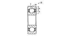
- a bearing 10 is arranged between an annular outer ring 2 made of JIS standard JIS2, an annular inner ring 1 arranged inside the outer ring 2, an outer ring 2 and an inner ring 1. And a plurality of balls 3 as rolling elements held by an annular cage 4.
- An outer ring raceway surface 2 ⁇ / b> A is formed on the inner peripheral surface of the outer ring 2, and an inner ring raceway surface 1 ⁇ / b> A is formed on the outer peripheral surface of the inner ring 1.
- the outer ring 2 and the inner ring 1 are arranged so that the inner ring raceway surface 1A and the outer ring raceway surface 2A face each other.
- the plurality of balls 3 come into contact with the inner ring raceway surface 1A and the outer ring raceway surface 2A on the ball rolling surface 3A that is the surface thereof, and are arranged at a predetermined pitch in the circumferential direction by the cage 4, thereby It is rotatably held on an annular track.
- the outer ring 2 and the inner ring 1 of the bearing 10 are rotatable relative to each other.
- At least the outer ring raceway surface 2A of the outer ring 2 is a region where a carbonitriding layer is formed.
- the inner ring raceway surface 1A of the inner ring 1 is also a region where a carbonitriding layer is formed.
- a carbonitriding layer is formed on the surface of the balls 3.
- the nitrogen concentration on the surface of the carbonitriding layer of the inner ring 1, the outer ring 2, and the balls 3 is 0.1% by mass or more.
- the inner ring 1, outer ring 2, and ball 3 as the bearing parts according to the present invention described above are bearing parts made of JIS standard SUJ2 and having a carbonitriding layer formed on the surface thereof, which will be described later.
- the Vickers hardness at a position 30 ⁇ m deep from the surface has the bearing parts (inner ring 1, outer ring 2).
- it is 130HV or higher than the Vickers hardness in the core, which is a region where the carbonitriding layer is not formed.
- the nitrogen concentration on the surface of the bearing component is 0.1% by mass or more, and as a result, the life of the bearing using the bearing component can be extended.
- the Vickers hardness at a position of 70 ⁇ m depth from the surface is It is preferably 80 HV or higher than the Vickers hardness at the core. This ensures that the nitrogen concentration on the surface of the carbonitrided layer before the heat treatment is 0.1% by mass or more.
- the difference between the region in the carbonitriding layer, the core, the Vickers hardness, and the nitrogen concentration has a linear relationship in the range where the nitrogen concentration is approximately 0 to 0.1% by mass. . Therefore, if the nitrogen concentration used for the determination is set to a value close to the center of the range showing the linear relationship (for example, 0.06% by mass), the correlation between the Vickers hardness difference and the nitrogen concentration is relatively good. Therefore, the accuracy of determination can be improved.
- the bearing parts (inner ring 1, outer ring 2, ball 3) according to the present invention are bearing parts made of JIS standard SUJ2 and having a carbonitriding layer formed on the surface, the heating temperature is 500 ° C., and the holding time is After the heat treatment for 1 hour, the Vickers hardness at a depth of 70 ⁇ m from the surface is 80 HV more than the Vickers hardness in the core, which is a region where the carbonitriding layer is not formed in the thickness direction of the bearing component. More expensive. In this way, as will be described later, it can be surely ensured that the nitrogen concentration on the surface of the carbonitriding layer before the heat treatment is 0.1% by mass or more.
- the nitrogen concentration in the surface of the carbonitriding layer, for example, the rolling surface is 0.1 mass% or more. In this case, it is possible to reliably extend the life of the bearing components (inner ring 1, outer ring 2, ball 3).
- the carbonitriding layer may be formed by a carbonitriding process in a temperature range in which a processing temperature is A 1 point or more and A cm point or less. In this case, a carbonitriding layer can be reliably formed in bearing parts such as the inner ring 1, the outer ring 2, and the balls 3.
- the carbonitriding layer may be formed by carbonitriding in a temperature range of 840 ° C. to 860 ° C., for example. In this case, a carbonitriding layer can be reliably formed in bearing parts such as the inner ring 1, the outer ring 2, and the balls 3.
- the bearing 10 according to the present invention is a bearing manufactured using the above bearing components such as the inner ring 1, the outer ring 2, and the ball 3. By doing so, the nitrogen concentration on the surface of the carbonitrided layer is quantitatively ensured, so that a bearing having a longer life than that of a bearing using an unnitrided bearing component can be obtained.
- the nitrogen concentration on the surface of bearing parts such as the inner ring 1, outer ring 2, and ball 3 constituting the bearing 10 shown in FIG. 1 can be inspected by the following inspection method.
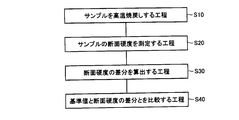
- a bearing component inspection method according to the present invention will be described with reference to FIG.
- Step (S10) is performed.
- the tempering temperature heat holding temperature
- the tempering time is 1 for example. It can be time.
- a step (S20) of measuring the cross-sectional hardness of the sample is performed as shown in FIG. Specifically, for example, when the inner ring 1 (see FIG. 1) is used as a sample, a test piece is cut out from the sample, and the test piece is cross-sectioned at a predetermined position in the thickness direction from the outer diameter side toward the inner diameter side. Measure hardness (Vickers hardness).
- the positions for measuring the hardness are, for example, two positions of 30 ⁇ m and 1 mm from the surface (outer diameter side surface), two positions of 70 ⁇ m and 1 mm from the surface, or 30 ⁇ m from the surface, 70 ⁇ m It is good also as three places called a position and a 1 mm position.
- a step of calculating a difference in cross-sectional hardness is performed. Specifically, the difference between the Vickers hardness at a position 1 mm from the surface corresponding to the core portion, which is an area other than the carbonitrided layer, and the Vickers hardness at a position 30 ⁇ m or 70 ⁇ m from the surface is calculated.
- a step of comparing the reference value and the difference in cross-sectional hardness is performed. Specifically, the reference value determined in advance is compared with the difference in cross-sectional hardness calculated in the step (S30), and whether the value of the difference satisfies the reference value (is greater than or equal to the reference value). Determine. If the difference value satisfies the reference value, it can be confirmed that the nitrogen concentration on the surface before the heat treatment (high temperature tempering) of the sample is a predetermined value (for example, 0.1% by mass).
- the inspection method is a bearing component (for example, inner ring 1, outer ring 2, ball 3, etc.) made of JIS standard SUJ2 and having a carbonitriding layer formed on the surface.
- a step of heat-treating the bearing part (S10), and after the heat treatment, at the position of the total depth from the surface plus the first distance to the grinding allowance for the surface A step (S20) of measuring the first Vickers hardness and the second Vickers hardness in the core portion which is a region where the carbonitriding layer is not formed in the thickness direction of the bearing component; and the first Vickers hardness is the second And (S30, S40) for determining whether or not it is higher than the Vickers hardness by a reference value.
- the heat treatment may be a heat treatment with a heating temperature of 500 ° C. and a holding time of 1 hour, the first distance may be 30 ⁇ m, and the reference value is 130 HV. Also good.
- the inventor that the correlation between the Vickers hardness and the nitrogen concentration after performing the heat treatment (high temperature tempering) as described above, and that the nitrogen distribution is moved to the inside in the thickness direction by approximately 30 ⁇ m by the heat treatment. Based on this knowledge, it can be determined whether or not the nitrogen concentration on the surface of the bearing part before the heat treatment is 0.1 mass% or more.
- the heat treatment may be a heat treatment with a heating temperature of 500 ° C. and a holding time of 1 hour, the first distance may be 70 ⁇ m, and the reference value is 80 HV. Also good. In this case, it can be determined with higher accuracy whether or not the nitrogen concentration on the surface of the bearing part before the heat treatment is 0.1 mass% or more.
- the nitrogen concentration confirmed on the surface of the carbonitriding layer in the bearing component is 0.1 mass% or more.
- the nitrogen concentration on the surface is at a level at which the effect of extending the life of the bearing component can be obtained, the effect of extending the life can be reliably obtained with the bearing component determined to be acceptable by the inspection method.
- the carbonitriding layer may be formed by a carbonitriding process in a temperature range in which the processing temperature is A 1 point or more and A cm point or less. Moreover, in the said inspection method, the carbonitriding layer may be formed by the carbonitriding process of the temperature range whose process temperature is 840 degreeC or more and 860 degrees C or less.
- Example 1 in order to apply the above-described inspection method according to the present invention to a bearing part actually made of JIS standard SUJ2, the measurement position and reference value of hardness were determined by the following procedure.
- the absolute value of the cross-sectional hardness itself is not used as an inspection index, but the hardness at a deep position (core portion) from the non-nitrided surface layer (here, for example, a depth of 1 mm from the outermost surface after heat treatment)
- the hardness difference (hardness difference) between the hardness at a certain depth in the nitrided region and the hardness of the nitrided region was adopted as an index of this inspection method.
- Table 1 shows the chemical components of the test specimens. All materials were JIS standard SUJ2, and these were subjected to carbonitriding in various heat treatment furnaces and heat treatment atmospheres. The carbonitriding temperature was included in the temperature range of 840 ° C. or higher and 860 ° C. or lower.
- the carbonitriding temperature was 850 ° C.
- the treatment time was 120 minutes (min) (hereinafter referred to as “850 ° C. ⁇ 120 min”)
- undecomposed NH 3 minutes The treatment was as follows: rate: 0.2 vol.%, Carbon activity: 0.9.
- the process of 840 degreeC x 70 min, undecomposed ammonia fraction: 0.1 vol.%, And carbon activity: 0.85 was performed.
- the process of 850 degreeC x 120 min, undecomposed ammonia fraction: 0.1 vol.%, And carbon activity: 0.9 was performed.
- test piece No. 5 was subjected to the treatment of 850 ° C. ⁇ 90 min, undecomposed ammonia fraction: 0.1 vol.%, And carbon activity: 0.9.
- test piece No. 6 was treated at 850 ° C. ⁇ 90 min, undecomposed ammonia fraction: 0.13 vol.%, And carbon activity: 0.9.
- test piece number 7 the process of 850 degreeC x 150 min, undecomposed ammonia fraction: 0.1 vol.%, And carbon activity: 0.85 was performed.
- test piece number 8 the process of 850 degreeC x 150 min, undecomposed ammonia fraction: 0.25 vol.%, And carbon activity: 0.9 was performed.
- test piece number 9 the process of 850 degreeC x 180 min, undecomposed ammonia fraction: 0.3 vol.%, Carbon activity: 0.95 was performed.
- the test piece number 10 the process of 850 degreeC * 90min, undecomposed ammonia fraction: 0.2 vol.%, And carbon activity: 0.9 was performed.
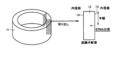
- the inner ring 1 (see FIG. 1) is used as the sample 11 as shown in FIG.
- the nitrogen concentration in the sample after carbonitriding was measured.
- a test piece 12 as shown in FIG. 3 is cut out from the sample 11, and the center of the test piece 12 in the height direction along the direction from the outer diameter side surface 13 to the inner diameter side surface 14 of the test piece.
- EPMA line analysis was performed on the cut end face at the part (position to be half-width).
- test piece described in the above (1-3) was subjected to hardness measurement at the cut end face subjected to EPMA analysis.
- Vickers hardness measurement was performed using a micro Vickers hardness meter.
- the hardness after tempering which has a relatively high correlation with the nitrogen concentration, is considered to be the hardness after tempering at a heating holding temperature of about 500 ° C.
- the cross-sectional hardness was measured on a test piece after high-temperature tempering with a heating holding temperature of 500 ° C. and a holding time of 1 hour.
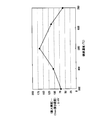
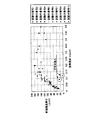
- the data indicated by the points surrounded by the broken line in FIG. 5 is considered to be caused by a decrease in hardness due to the occurrence of incomplete quenching. Excluding these, the relationship between the nitrogen concentration and the cross-sectional hardness difference in the range of 0 to 0.1% by mass was extracted and rearranged in FIG.
- the horizontal axis represents the nitrogen concentration (unit: mass%)
- the vertical axis represents the cross-sectional hardness difference: ⁇ HV (unit: Vickers hardness).
- the outermost surface after grinding (that is, the outermost surface of the final bearing component) of the rolling surface that is the surface of the region where the carbonitriding layer is formed in the bearing component Proposes an inspection method (quality assurance method) to ensure that the nitrogen concentration of the product is a predetermined value (for example, 0.1% by mass or more), and guarantees the nitrogen concentration based on the inspection method
- a predetermined value for example, 0.1% by mass or more
- the maximum distance between the depth position where the nitrogen concentration is 0.1 mass% and the depth position where the nitrogen concentration is 0.06 mass% is 40 ⁇ m. Therefore, when considering from FIG. 8 and the like, the nitrogen concentration is 0.1 mass in the range from the position where the nitrogen concentration is 0.06 mass% closer to the surface side of the carbonitrided product by 40 ⁇ m to the surface. % Or more. Therefore, if the cross-sectional hardness difference ( ⁇ HV) at a certain depth position is 80 or more, it can be guaranteed that the nitrogen concentration in the region close to the surface by 40 ⁇ m from the depth position is 0.1 mass% or more. Become. Note that, under the four conditions shown in FIG. 8, the nitrogen concentration in the region shifted to the surface side by 40 ⁇ m from the depth position where the nitrogen concentration becomes 0.06% by mass is calculated to be the value shown in Table 2. .
- nitriding time carbonitriding time
- undecomposed NH 3 volume fraction nitrogen in a region shifted to the surface side by 40 ⁇ m from the depth position where the nitrogen concentration becomes 0.06% by mass
- the nitrogen concentration on the outermost surface after grinding corresponding to the concentration is described.
- the nitrogen concentration in the region is 0.1% by mass or more.
- Table 3 the test piece number from the left, the nitrogen concentration (unit: mass%) in the region where the depth from the sample surface was measured, the depth from the test piece surface to the relevant region before high temperature tempering ( (Unit: ⁇ m), depth from the specimen surface to the region after high-temperature tempering (unit: ⁇ m), distance traveled in the depth direction by high-temperature tempering (unit: ⁇ m), The average value (unit: ⁇ m) of the moving distance of the region for each nitrogen concentration is shown.
- the region where the nitrogen concentration becomes 0.05 mass% or the nitrogen concentration becomes 0.1 mass% by high-temperature tempering is about 30 ⁇ m on average toward the inside of the test piece. I found it moving. Then, according to (3-3) above, the nitrogen concentration between the region where the nitrogen concentration is 0.06% by mass from the region close to the surface side by 40 ⁇ m (shallow) to the surface is 0.1% by mass or more. In order to ensure that the nitrogen concentration on the outermost surface after grinding before high temperature tempering (500 ° C. ⁇ 1 h tempering) is 0.1% by mass or more, high temperature tempering (500 ° C.
- the maximum distance between the depth at which the nitrogen concentration is 0.1% by mass and the depth at which the nitrogen concentration is 0.06% by mass is 40 ⁇ m
- the nitrogen moving distance by high temperature tempering 500 ° C. ⁇ 1 h tempering
- the total distance (70 ⁇ m) of the maximum distance (40 ⁇ m) and the nitrogen moving distance (30 ⁇ m) is considered.
- the nitrogen concentration at the depth position obtained by adding the grinding allowance (only one surface) of the bearing parts after carbonitriding to the total distance is 0.06% by mass or more (that is, high temperature tempering (500 ° C.
- the moving distance in the depth direction of the position where the nitrogen concentration by high-temperature tempering (500 ° C. ⁇ 1 h tempering) is 0.05 mass% and the nitrogen concentration is 0.1 mass%.
- the carbonitriding sample (the bearing component heat-treated product) is cut and subjected to the above-described high-temperature tempering (500 ° C. ⁇ 1 h tempering).
- test piece for measuring the cross-sectional hardness for example, fill the test piece with resin so that the cross-sectional hardness can be measured, and prepare a sample for measuring the hardness).
- the test piece should be exposed so that the end face for the hardness measurement is exposed so that the hardness measurement can be performed at a predetermined position in the depth direction from the surface serving as the rolling surface of the bearing part toward the inside of the bearing part.
- the above-described inspection method does not require the introduction of new equipment and can be said to be a very simple inspection.
- this inspection method quality assurance method is considered to be an appropriate method for determining that the nitrogen concentration at the outermost surface position after grinding is 0.1% by mass or more.
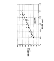
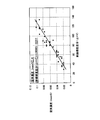
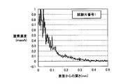
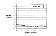
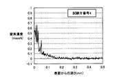
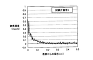
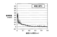
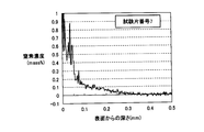
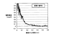
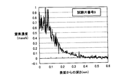
- FIGS. 9 to 18 actual measurement values of nitrogen concentration distribution before high-temperature tempering (500 ° C. ⁇ 1 h tempering) of each test piece are shown in FIGS. 9 to 18, the horizontal axis represents the depth from the surface (unit: mm), and the vertical axis represents the nitrogen concentration (unit: mass%).
- the test piece is subjected to high-temperature tempering (500 ° C. ⁇ 1 h tempering). It can be said that it is only necessary to measure the cross-sectional hardness at a position of a depth of one-side grinding allowance +70 ⁇ m from the surface and a position of a depth of 1 mm from the surface to ensure that the difference in cross-sectional hardness is 80 or more.
- the above-mentioned one-side grinding allowance does not have to be taken into account as the measurement position of the cross-sectional hardness.
- the nitrogen concentration on the surface of the test piece before high temperature tempering for example, the surface after grinding
- one-side grinding is performed from the surface of the test piece after high temperature tempering (500 ° C. ⁇ 1 h tempering). It can be said that it is only necessary to measure the cross-sectional hardness at the position of the machining allowance +30 ⁇ m and the position of the depth of 1 mm from the surface to ensure that the difference in cross-sectional hardness is 130 or more.
- the present invention is particularly advantageously applied to carbonitrided bearing parts and bearings.
Landscapes
- Chemical & Material Sciences (AREA)
- Engineering & Computer Science (AREA)
- Mechanical Engineering (AREA)
- Organic Chemistry (AREA)
- General Engineering & Computer Science (AREA)
- Materials Engineering (AREA)
- Metallurgy (AREA)
- Chemical Kinetics & Catalysis (AREA)
- Crystallography & Structural Chemistry (AREA)
- Physics & Mathematics (AREA)
- Thermal Sciences (AREA)
- Manufacturing & Machinery (AREA)
- Rolling Contact Bearings (AREA)
- Solid-Phase Diffusion Into Metallic Material Surfaces (AREA)
- Heat Treatment Of Articles (AREA)
- Testing Of Devices, Machine Parts, Or Other Structures Thereof (AREA)
Priority Applications (3)
| Application Number | Priority Date | Filing Date | Title |
|---|---|---|---|
| CN2011800173096A CN102859025A (zh) | 2010-03-29 | 2011-03-29 | 轴承零件、轴承及轴承零件的检查方法 |
| EP11762856.0A EP2554709B1 (en) | 2010-03-29 | 2011-03-29 | Bearing part inspection method |
| US13/637,954 US9032783B2 (en) | 2010-03-29 | 2011-03-29 | Bearing part, bearing, and method for inspecting bearing part |
Applications Claiming Priority (2)
| Application Number | Priority Date | Filing Date | Title |
|---|---|---|---|
| JP2010075370A JP5679543B2 (ja) | 2010-03-29 | 2010-03-29 | 軸受部品および軸受 |
| JP2010-075370 | 2010-03-29 |
Publications (1)
| Publication Number | Publication Date |
|---|---|
| WO2011122632A1 true WO2011122632A1 (ja) | 2011-10-06 |
Family
ID=44712327
Family Applications (1)
| Application Number | Title | Priority Date | Filing Date |
|---|---|---|---|
| PCT/JP2011/057849 Ceased WO2011122632A1 (ja) | 2010-03-29 | 2011-03-29 | 軸受部品、軸受および軸受部品の検査方法 |
Country Status (5)
| Country | Link |
|---|---|
| US (1) | US9032783B2 (enExample) |
| EP (1) | EP2554709B1 (enExample) |
| JP (1) | JP5679543B2 (enExample) |
| CN (1) | CN102859025A (enExample) |
| WO (1) | WO2011122632A1 (enExample) |
Cited By (6)
| Publication number | Priority date | Publication date | Assignee | Title |
|---|---|---|---|---|
| WO2014061699A1 (ja) * | 2012-10-17 | 2014-04-24 | Ntn株式会社 | 軸受部品、転がり軸受および軸受部品の製造方法 |
| CN104540970A (zh) * | 2012-08-21 | 2015-04-22 | Skf公司 | 热处理钢构件的方法及钢构件 |
| US10087989B2 (en) | 2013-06-06 | 2018-10-02 | Ntn Corporation | Bearing component and rolling bearing |
| US10094422B2 (en) | 2013-06-06 | 2018-10-09 | Ntn Corporation | Bearing component and rolling bearing |
| US10107335B2 (en) | 2013-06-06 | 2018-10-23 | Ntn Corporation | Bearing component and rolling bearing |
| US10156259B2 (en) | 2013-06-06 | 2018-12-18 | Ntn Corporation | Bearing component and rolling bearing |
Families Citing this family (4)
| Publication number | Priority date | Publication date | Assignee | Title |
|---|---|---|---|---|
| DE102012212426B3 (de) * | 2012-07-16 | 2013-08-29 | Schaeffler Technologies AG & Co. KG | Wälzlagerelement, insbesondere Wälzlagerring |
| JP6241638B2 (ja) * | 2012-08-22 | 2017-12-06 | 三菱日立パワーシステムズ株式会社 | 時効条件設定方法及びタービン翼の製造方法 |
| JP6026915B2 (ja) | 2013-02-13 | 2016-11-16 | Ntn株式会社 | 軸受部品および転がり軸受の検査方法 |
| CN104328373A (zh) * | 2014-10-22 | 2015-02-04 | 人本集团有限公司 | 一种高碳铬轴承钢碳氮共渗有效硬化层深度检测方法 |
Citations (4)
| Publication number | Priority date | Publication date | Assignee | Title |
|---|---|---|---|---|
| JPH05240253A (ja) * | 1992-02-28 | 1993-09-17 | Ntn Corp | 転動体を有する機械部品 |
| JP2962817B2 (ja) | 1990-11-28 | 1999-10-12 | 日本精工株式会社 | 転がり軸受 |
| JPH11304795A (ja) * | 1998-04-21 | 1999-11-05 | Nippon Seiko Kk | 鋼部品の窒素侵入深さ検出方法 |
| JP2009229288A (ja) | 2008-03-24 | 2009-10-08 | Ntn Corp | 転動疲労寿命の試験方法 |
Family Cites Families (7)
| Publication number | Priority date | Publication date | Assignee | Title |
|---|---|---|---|---|
| DE69323909T2 (de) | 1993-09-08 | 1999-09-16 | Ntn Corp., Osaka | Mechanisches teil mit rollelementen |
| TW408212B (en) * | 1996-10-11 | 2000-10-11 | Sanyo Electric Co | Method for treating metal surface, rotary shaft and vane for refrigerant compressor treated by the method, and refrigerant compressor using the same |
| JP3702618B2 (ja) * | 1997-11-04 | 2005-10-05 | 日本精工株式会社 | トロイダル形無段変速機 |
| JP2001280348A (ja) * | 2000-03-28 | 2001-10-10 | Nsk Ltd | 転がり軸受 |
| JP4423754B2 (ja) * | 2000-06-22 | 2010-03-03 | 日本精工株式会社 | 転動軸の製造方法 |
| ATE509139T1 (de) * | 2001-03-30 | 2011-05-15 | Hitachi Metals Ltd | Beschichtetes schneidwerkzeug für warm/und heissverformen |
| EP2025765A4 (en) * | 2006-05-19 | 2014-05-28 | Nsk Ltd | BEARING BEARING |
-
2010
- 2010-03-29 JP JP2010075370A patent/JP5679543B2/ja active Active
-
2011
- 2011-03-29 EP EP11762856.0A patent/EP2554709B1/en active Active
- 2011-03-29 CN CN2011800173096A patent/CN102859025A/zh active Pending
- 2011-03-29 WO PCT/JP2011/057849 patent/WO2011122632A1/ja not_active Ceased
- 2011-03-29 US US13/637,954 patent/US9032783B2/en active Active
Patent Citations (4)
| Publication number | Priority date | Publication date | Assignee | Title |
|---|---|---|---|---|
| JP2962817B2 (ja) | 1990-11-28 | 1999-10-12 | 日本精工株式会社 | 転がり軸受 |
| JPH05240253A (ja) * | 1992-02-28 | 1993-09-17 | Ntn Corp | 転動体を有する機械部品 |
| JPH11304795A (ja) * | 1998-04-21 | 1999-11-05 | Nippon Seiko Kk | 鋼部品の窒素侵入深さ検出方法 |
| JP2009229288A (ja) | 2008-03-24 | 2009-10-08 | Ntn Corp | 転動疲労寿命の試験方法 |
Non-Patent Citations (4)
| Title |
|---|
| CHIKARA OHKI: "Nitrogen Concentration Distribution Prediction in SUJ2 Subjected to Carbonitriding Treatment", IRON AND STEEL, vol. 93, 2007, pages 220 |
| HYOJIRO KURABE ET AL.: "Rolling Fatigue Characteristics of Carburized or Carbonitrided 1% Cr Steel at Elevated Temperatures", IRON AND STEEL, vol. 11, 1967, pages 1305 |
| See also references of EP2554709A4 * |
| YOUICHI WATANABE ET AL.: "Effects of Nitrogen Content on Microstructure and Resistance to Softening during Tempering of Carbo-Nitrided Chromium Alloy Steels", HEAT TREATMENT, vol. 40, 2000, pages 18 |
Cited By (10)
| Publication number | Priority date | Publication date | Assignee | Title |
|---|---|---|---|---|
| CN104540970A (zh) * | 2012-08-21 | 2015-04-22 | Skf公司 | 热处理钢构件的方法及钢构件 |
| WO2014061699A1 (ja) * | 2012-10-17 | 2014-04-24 | Ntn株式会社 | 軸受部品、転がり軸受および軸受部品の製造方法 |
| CN104718305A (zh) * | 2012-10-17 | 2015-06-17 | Ntn株式会社 | 轴承部件、滚动轴承以及轴承部件的制造方法 |
| EP2910657A4 (en) * | 2012-10-17 | 2016-09-14 | Ntn Toyo Bearing Co Ltd | BEARING MEMBER, ROLLER BEARING AND METHOD FOR PRODUCING A BEARING ELEMENT |
| CN104718305B (zh) * | 2012-10-17 | 2018-03-20 | Ntn株式会社 | 轴承部件、滚动轴承以及轴承部件的制造方法 |
| US9951816B2 (en) | 2012-10-17 | 2018-04-24 | Ntn Corporation | Bearing part, rolling bearing, and method for manufacturing bearing part |
| US10087989B2 (en) | 2013-06-06 | 2018-10-02 | Ntn Corporation | Bearing component and rolling bearing |
| US10094422B2 (en) | 2013-06-06 | 2018-10-09 | Ntn Corporation | Bearing component and rolling bearing |
| US10107335B2 (en) | 2013-06-06 | 2018-10-23 | Ntn Corporation | Bearing component and rolling bearing |
| US10156259B2 (en) | 2013-06-06 | 2018-12-18 | Ntn Corporation | Bearing component and rolling bearing |
Also Published As
| Publication number | Publication date |
|---|---|
| JP2011209021A (ja) | 2011-10-20 |
| JP5679543B2 (ja) | 2015-03-04 |
| CN102859025A (zh) | 2013-01-02 |
| US20130019666A1 (en) | 2013-01-24 |
| EP2554709B1 (en) | 2020-10-07 |
| US9032783B2 (en) | 2015-05-19 |
| EP2554709A1 (en) | 2013-02-06 |
| EP2554709A4 (en) | 2014-05-28 |
Similar Documents
| Publication | Publication Date | Title |
|---|---|---|
| JP5679543B2 (ja) | 軸受部品および軸受 | |
| EP2910657B1 (en) | Bearing element, rolling bearing and process for producing bearing element | |
| JP6211811B2 (ja) | 軸受部品および転がり軸受 | |
| WO2014196428A1 (ja) | 軸受部品および転がり軸受 | |
| EP3006754A1 (en) | Bearing component and rolling bearing | |
| JP5592540B1 (ja) | 軸受部品および転がり軸受 | |
| JP6026915B2 (ja) | 軸受部品および転がり軸受の検査方法 | |
| JP6211814B2 (ja) | 軸受部品および転がり軸受 | |
| EP3006577B1 (en) | Bearing component and rolling bearing | |
| JP5592541B1 (ja) | 軸受部品および転がり軸受 | |
| JP6211813B2 (ja) | 軸受部品および転がり軸受 | |
| JP6211815B2 (ja) | 軸受部品および転がり軸受 | |
| JP6211812B2 (ja) | 軸受部品および転がり軸受 | |
| JP2014237871A (ja) | 軸受部品および転がり軸受 | |
| WO2014196429A1 (ja) | 軸受部品および転がり軸受 |
Legal Events
| Date | Code | Title | Description |
|---|---|---|---|
| WWE | Wipo information: entry into national phase |
Ref document number: 201180017309.6 Country of ref document: CN |
|
| 121 | Ep: the epo has been informed by wipo that ep was designated in this application |
Ref document number: 11762856 Country of ref document: EP Kind code of ref document: A1 |
|
| WWE | Wipo information: entry into national phase |
Ref document number: 13637954 Country of ref document: US |
|
| NENP | Non-entry into the national phase |
Ref country code: DE |
|
| WWE | Wipo information: entry into national phase |
Ref document number: 2011762856 Country of ref document: EP |