EP2554709A1 - Bearing part, bearing and bearing part inspection method - Google Patents
Bearing part, bearing and bearing part inspection method Download PDFInfo
- Publication number
- EP2554709A1 EP2554709A1 EP11762856A EP11762856A EP2554709A1 EP 2554709 A1 EP2554709 A1 EP 2554709A1 EP 11762856 A EP11762856 A EP 11762856A EP 11762856 A EP11762856 A EP 11762856A EP 2554709 A1 EP2554709 A1 EP 2554709A1
- Authority
- EP
- European Patent Office
- Prior art keywords
- bearing part
- nitrogen concentration
- heat treatment
- mass
- less
- Prior art date
- Legal status (The legal status is an assumption and is not a legal conclusion. Google has not performed a legal analysis and makes no representation as to the accuracy of the status listed.)
- Granted
Links
Images


Classifications
-
- C—CHEMISTRY; METALLURGY
- C23—COATING METALLIC MATERIAL; COATING MATERIAL WITH METALLIC MATERIAL; CHEMICAL SURFACE TREATMENT; DIFFUSION TREATMENT OF METALLIC MATERIAL; COATING BY VACUUM EVAPORATION, BY SPUTTERING, BY ION IMPLANTATION OR BY CHEMICAL VAPOUR DEPOSITION, IN GENERAL; INHIBITING CORROSION OF METALLIC MATERIAL OR INCRUSTATION IN GENERAL
- C23C—COATING METALLIC MATERIAL; COATING MATERIAL WITH METALLIC MATERIAL; SURFACE TREATMENT OF METALLIC MATERIAL BY DIFFUSION INTO THE SURFACE, BY CHEMICAL CONVERSION OR SUBSTITUTION; COATING BY VACUUM EVAPORATION, BY SPUTTERING, BY ION IMPLANTATION OR BY CHEMICAL VAPOUR DEPOSITION, IN GENERAL
- C23C8/00—Solid state diffusion of only non-metal elements into metallic material surfaces; Chemical surface treatment of metallic material by reaction of the surface with a reactive gas, leaving reaction products of surface material in the coating, e.g. conversion coatings, passivation of metals
- C23C8/06—Solid state diffusion of only non-metal elements into metallic material surfaces; Chemical surface treatment of metallic material by reaction of the surface with a reactive gas, leaving reaction products of surface material in the coating, e.g. conversion coatings, passivation of metals using gases
- C23C8/28—Solid state diffusion of only non-metal elements into metallic material surfaces; Chemical surface treatment of metallic material by reaction of the surface with a reactive gas, leaving reaction products of surface material in the coating, e.g. conversion coatings, passivation of metals using gases more than one element being applied in one step
- C23C8/30—Carbo-nitriding
- C23C8/32—Carbo-nitriding of ferrous surfaces
-
- C—CHEMISTRY; METALLURGY
- C21—METALLURGY OF IRON
- C21D—MODIFYING THE PHYSICAL STRUCTURE OF FERROUS METALS; GENERAL DEVICES FOR HEAT TREATMENT OF FERROUS OR NON-FERROUS METALS OR ALLOYS; MAKING METAL MALLEABLE, e.g. BY DECARBURISATION OR TEMPERING
- C21D1/00—General methods or devices for heat treatment, e.g. annealing, hardening, quenching or tempering
- C21D1/06—Surface hardening
-
- C—CHEMISTRY; METALLURGY
- C21—METALLURGY OF IRON
- C21D—MODIFYING THE PHYSICAL STRUCTURE OF FERROUS METALS; GENERAL DEVICES FOR HEAT TREATMENT OF FERROUS OR NON-FERROUS METALS OR ALLOYS; MAKING METAL MALLEABLE, e.g. BY DECARBURISATION OR TEMPERING
- C21D9/00—Heat treatment, e.g. annealing, hardening, quenching or tempering, adapted for particular articles; Furnaces therefor
- C21D9/40—Heat treatment, e.g. annealing, hardening, quenching or tempering, adapted for particular articles; Furnaces therefor for rings; for bearing races
-
- C—CHEMISTRY; METALLURGY
- C23—COATING METALLIC MATERIAL; COATING MATERIAL WITH METALLIC MATERIAL; CHEMICAL SURFACE TREATMENT; DIFFUSION TREATMENT OF METALLIC MATERIAL; COATING BY VACUUM EVAPORATION, BY SPUTTERING, BY ION IMPLANTATION OR BY CHEMICAL VAPOUR DEPOSITION, IN GENERAL; INHIBITING CORROSION OF METALLIC MATERIAL OR INCRUSTATION IN GENERAL
- C23C—COATING METALLIC MATERIAL; COATING MATERIAL WITH METALLIC MATERIAL; SURFACE TREATMENT OF METALLIC MATERIAL BY DIFFUSION INTO THE SURFACE, BY CHEMICAL CONVERSION OR SUBSTITUTION; COATING BY VACUUM EVAPORATION, BY SPUTTERING, BY ION IMPLANTATION OR BY CHEMICAL VAPOUR DEPOSITION, IN GENERAL
- C23C8/00—Solid state diffusion of only non-metal elements into metallic material surfaces; Chemical surface treatment of metallic material by reaction of the surface with a reactive gas, leaving reaction products of surface material in the coating, e.g. conversion coatings, passivation of metals
- C23C8/40—Solid state diffusion of only non-metal elements into metallic material surfaces; Chemical surface treatment of metallic material by reaction of the surface with a reactive gas, leaving reaction products of surface material in the coating, e.g. conversion coatings, passivation of metals using liquids, e.g. salt baths, liquid suspensions
- C23C8/52—Solid state diffusion of only non-metal elements into metallic material surfaces; Chemical surface treatment of metallic material by reaction of the surface with a reactive gas, leaving reaction products of surface material in the coating, e.g. conversion coatings, passivation of metals using liquids, e.g. salt baths, liquid suspensions more than one element being applied in one step
- C23C8/54—Carbo-nitriding
- C23C8/56—Carbo-nitriding of ferrous surfaces
-
- C—CHEMISTRY; METALLURGY
- C23—COATING METALLIC MATERIAL; COATING MATERIAL WITH METALLIC MATERIAL; CHEMICAL SURFACE TREATMENT; DIFFUSION TREATMENT OF METALLIC MATERIAL; COATING BY VACUUM EVAPORATION, BY SPUTTERING, BY ION IMPLANTATION OR BY CHEMICAL VAPOUR DEPOSITION, IN GENERAL; INHIBITING CORROSION OF METALLIC MATERIAL OR INCRUSTATION IN GENERAL
- C23C—COATING METALLIC MATERIAL; COATING MATERIAL WITH METALLIC MATERIAL; SURFACE TREATMENT OF METALLIC MATERIAL BY DIFFUSION INTO THE SURFACE, BY CHEMICAL CONVERSION OR SUBSTITUTION; COATING BY VACUUM EVAPORATION, BY SPUTTERING, BY ION IMPLANTATION OR BY CHEMICAL VAPOUR DEPOSITION, IN GENERAL
- C23C8/00—Solid state diffusion of only non-metal elements into metallic material surfaces; Chemical surface treatment of metallic material by reaction of the surface with a reactive gas, leaving reaction products of surface material in the coating, e.g. conversion coatings, passivation of metals
- C23C8/60—Solid state diffusion of only non-metal elements into metallic material surfaces; Chemical surface treatment of metallic material by reaction of the surface with a reactive gas, leaving reaction products of surface material in the coating, e.g. conversion coatings, passivation of metals using solids, e.g. powders, pastes
- C23C8/72—Solid state diffusion of only non-metal elements into metallic material surfaces; Chemical surface treatment of metallic material by reaction of the surface with a reactive gas, leaving reaction products of surface material in the coating, e.g. conversion coatings, passivation of metals using solids, e.g. powders, pastes more than one element being applied in one step
- C23C8/74—Carbo-nitriding
- C23C8/76—Carbo-nitriding of ferrous surfaces
-
- C—CHEMISTRY; METALLURGY
- C23—COATING METALLIC MATERIAL; COATING MATERIAL WITH METALLIC MATERIAL; CHEMICAL SURFACE TREATMENT; DIFFUSION TREATMENT OF METALLIC MATERIAL; COATING BY VACUUM EVAPORATION, BY SPUTTERING, BY ION IMPLANTATION OR BY CHEMICAL VAPOUR DEPOSITION, IN GENERAL; INHIBITING CORROSION OF METALLIC MATERIAL OR INCRUSTATION IN GENERAL
- C23C—COATING METALLIC MATERIAL; COATING MATERIAL WITH METALLIC MATERIAL; SURFACE TREATMENT OF METALLIC MATERIAL BY DIFFUSION INTO THE SURFACE, BY CHEMICAL CONVERSION OR SUBSTITUTION; COATING BY VACUUM EVAPORATION, BY SPUTTERING, BY ION IMPLANTATION OR BY CHEMICAL VAPOUR DEPOSITION, IN GENERAL
- C23C8/00—Solid state diffusion of only non-metal elements into metallic material surfaces; Chemical surface treatment of metallic material by reaction of the surface with a reactive gas, leaving reaction products of surface material in the coating, e.g. conversion coatings, passivation of metals
- C23C8/80—After-treatment
-
- F—MECHANICAL ENGINEERING; LIGHTING; HEATING; WEAPONS; BLASTING
- F16—ENGINEERING ELEMENTS AND UNITS; GENERAL MEASURES FOR PRODUCING AND MAINTAINING EFFECTIVE FUNCTIONING OF MACHINES OR INSTALLATIONS; THERMAL INSULATION IN GENERAL
- F16C—SHAFTS; FLEXIBLE SHAFTS; ELEMENTS OR CRANKSHAFT MECHANISMS; ROTARY BODIES OTHER THAN GEARING ELEMENTS; BEARINGS
- F16C33/00—Parts of bearings; Special methods for making bearings or parts thereof
- F16C33/30—Parts of ball or roller bearings
- F16C33/32—Balls
-
- F—MECHANICAL ENGINEERING; LIGHTING; HEATING; WEAPONS; BLASTING
- F16—ENGINEERING ELEMENTS AND UNITS; GENERAL MEASURES FOR PRODUCING AND MAINTAINING EFFECTIVE FUNCTIONING OF MACHINES OR INSTALLATIONS; THERMAL INSULATION IN GENERAL
- F16C—SHAFTS; FLEXIBLE SHAFTS; ELEMENTS OR CRANKSHAFT MECHANISMS; ROTARY BODIES OTHER THAN GEARING ELEMENTS; BEARINGS
- F16C33/00—Parts of bearings; Special methods for making bearings or parts thereof
- F16C33/30—Parts of ball or roller bearings
- F16C33/58—Raceways; Race rings
- F16C33/62—Selection of substances
-
- F—MECHANICAL ENGINEERING; LIGHTING; HEATING; WEAPONS; BLASTING
- F16—ENGINEERING ELEMENTS AND UNITS; GENERAL MEASURES FOR PRODUCING AND MAINTAINING EFFECTIVE FUNCTIONING OF MACHINES OR INSTALLATIONS; THERMAL INSULATION IN GENERAL
- F16C—SHAFTS; FLEXIBLE SHAFTS; ELEMENTS OR CRANKSHAFT MECHANISMS; ROTARY BODIES OTHER THAN GEARING ELEMENTS; BEARINGS
- F16C33/00—Parts of bearings; Special methods for making bearings or parts thereof
- F16C33/30—Parts of ball or roller bearings
- F16C33/58—Raceways; Race rings
- F16C33/64—Special methods of manufacture
-
- F—MECHANICAL ENGINEERING; LIGHTING; HEATING; WEAPONS; BLASTING
- F16—ENGINEERING ELEMENTS AND UNITS; GENERAL MEASURES FOR PRODUCING AND MAINTAINING EFFECTIVE FUNCTIONING OF MACHINES OR INSTALLATIONS; THERMAL INSULATION IN GENERAL
- F16C—SHAFTS; FLEXIBLE SHAFTS; ELEMENTS OR CRANKSHAFT MECHANISMS; ROTARY BODIES OTHER THAN GEARING ELEMENTS; BEARINGS
- F16C2202/00—Solid materials defined by their properties
- F16C2202/02—Mechanical properties
- F16C2202/04—Hardness
-
- F—MECHANICAL ENGINEERING; LIGHTING; HEATING; WEAPONS; BLASTING
- F16—ENGINEERING ELEMENTS AND UNITS; GENERAL MEASURES FOR PRODUCING AND MAINTAINING EFFECTIVE FUNCTIONING OF MACHINES OR INSTALLATIONS; THERMAL INSULATION IN GENERAL
- F16C—SHAFTS; FLEXIBLE SHAFTS; ELEMENTS OR CRANKSHAFT MECHANISMS; ROTARY BODIES OTHER THAN GEARING ELEMENTS; BEARINGS
- F16C2204/00—Metallic materials; Alloys
- F16C2204/60—Ferrous alloys, e.g. steel alloys
- F16C2204/66—High carbon steel, i.e. carbon content above 0.8 wt%, e.g. through-hardenable steel
-
- F—MECHANICAL ENGINEERING; LIGHTING; HEATING; WEAPONS; BLASTING
- F16—ENGINEERING ELEMENTS AND UNITS; GENERAL MEASURES FOR PRODUCING AND MAINTAINING EFFECTIVE FUNCTIONING OF MACHINES OR INSTALLATIONS; THERMAL INSULATION IN GENERAL
- F16C—SHAFTS; FLEXIBLE SHAFTS; ELEMENTS OR CRANKSHAFT MECHANISMS; ROTARY BODIES OTHER THAN GEARING ELEMENTS; BEARINGS
- F16C2223/00—Surface treatments; Hardening; Coating
- F16C2223/10—Hardening, e.g. carburizing, carbo-nitriding
- F16C2223/16—Hardening, e.g. carburizing, carbo-nitriding with carbo-nitriding
-
- F—MECHANICAL ENGINEERING; LIGHTING; HEATING; WEAPONS; BLASTING
- F16—ENGINEERING ELEMENTS AND UNITS; GENERAL MEASURES FOR PRODUCING AND MAINTAINING EFFECTIVE FUNCTIONING OF MACHINES OR INSTALLATIONS; THERMAL INSULATION IN GENERAL
- F16C—SHAFTS; FLEXIBLE SHAFTS; ELEMENTS OR CRANKSHAFT MECHANISMS; ROTARY BODIES OTHER THAN GEARING ELEMENTS; BEARINGS
- F16C2240/00—Specified values or numerical ranges of parameters; Relations between them
- F16C2240/06—Temperature
-
- F—MECHANICAL ENGINEERING; LIGHTING; HEATING; WEAPONS; BLASTING
- F16—ENGINEERING ELEMENTS AND UNITS; GENERAL MEASURES FOR PRODUCING AND MAINTAINING EFFECTIVE FUNCTIONING OF MACHINES OR INSTALLATIONS; THERMAL INSULATION IN GENERAL
- F16C—SHAFTS; FLEXIBLE SHAFTS; ELEMENTS OR CRANKSHAFT MECHANISMS; ROTARY BODIES OTHER THAN GEARING ELEMENTS; BEARINGS
- F16C2240/00—Specified values or numerical ranges of parameters; Relations between them
- F16C2240/08—Time
-
- F—MECHANICAL ENGINEERING; LIGHTING; HEATING; WEAPONS; BLASTING
- F16—ENGINEERING ELEMENTS AND UNITS; GENERAL MEASURES FOR PRODUCING AND MAINTAINING EFFECTIVE FUNCTIONING OF MACHINES OR INSTALLATIONS; THERMAL INSULATION IN GENERAL
- F16C—SHAFTS; FLEXIBLE SHAFTS; ELEMENTS OR CRANKSHAFT MECHANISMS; ROTARY BODIES OTHER THAN GEARING ELEMENTS; BEARINGS
- F16C2240/00—Specified values or numerical ranges of parameters; Relations between them
- F16C2240/40—Linear dimensions, e.g. length, radius, thickness, gap
- F16C2240/60—Thickness, e.g. thickness of coatings
Definitions
- the present invention relates to a bearing part, a bearing, and a method for inspecting a bearing part. More specifically, the present invention relates to a bearing part, a bearing, and a method for inspecting a bearing part subjected to carbonitriding treatment.
- Non-Patent Literature 1 Rolling Fatigue Characteristics of Carburized or Carbonitrided 1% Cr Steel at Elevated Temperatures
- Patent Literature 1 Japanese Patent No. 2962817
- Patent Literature 2 2009-229288
- a nitrogen concentration in steel can be quantified only by a method performed using analysis equipment such as an EPMA (Electron Probe Micro Analyzer) and a GDS (Glow Discharge Spectrometer), and such measurement requires a great number of man-hours. Therefore, if a method using analysis equipment as described above is adopted as an inspection method for quality assurance, the rolling bearing becomes very expensive, which is not practical.
- EPMA Electro Probe Micro Analyzer
- GDS Glow Discharge Spectrometer
- Non-Patent Literature 2 a method for qualitatively evaluating the degree of nitridation by utilizing the characteristics of nitrogen which has entered steel that "the hardness after high-temperature tempering is higher than that of a non-nitrided portion" is described, for example, in “ Effects of Nitrogen Content on Microstructure and Resistance to Softening during Tempering of Carbo-Nitrided Chromium Alloy Steels" by Youichi Watanabe et al., Heat Treatment, vol. 40, (2000), p. 18 (hereinafter referred to as Non-Patent Literature 2), and the like.
- the present invention has been made to solve aforementioned problems, and one object of the present invention is to provide an inspection method which quantitatively and simply assures a nitrogen concentration in a carbonitriding-treated bearing part, and a bearing part and a bearing for which a nitrogen concentration is quantitatively assured.
- a bearing part in accordance with the present invention is a bearing part made of JIS standard SUJ2 and having a carbonitrided layer formed in a surface thereof, wherein, after heat treatment at a heating temperature of 500°C for a retention time of one hour is performed, a Vickers hardness at a position with a depth of 30 ⁇ m from the surface is higher than a Vickers hardness at a core portion, which is a region where the carbonitrided layer is not formed in a thickness direction of the bearing part, by not less than 130 HV.
- the inventor has obtained fmdings that, in the bearing part made of JIS standard SUJ2, there is a correlation between a Vickers hardness and a nitrogen concentration in the carbonitrided layer subjected to heat treatment under conditions as described above, and that nitrogen distribution is shifted toward an inner side in the thickness direction by a predetermined distance (30 ⁇ m) due to the heat treatment.
- the Vickers hardness at the position with the depth of 30 ⁇ m from the surface subjected to heat treatment as described above is higher than that in a region not subjected to carbonitriding treatment by a predetermined value, in accordance with the nitrogen concentration at the position (i.e., the nitrogen concentration in the surface of the bearing part before the heat treatment is performed).
- the bearing part in accordance with the present invention can assure that the nitrogen concentration in the surface before the heat treatment is not less than 0.1 mass %.
- a Vickers hardness at a position with a depth of 70 ⁇ m from the surface is higher than the Vickers hardness at the core portion by not less than 80 HV.
- the maximum distance in a depth direction between a position having a nitrogen concentration of 0.1 mass % and a position having a nitrogen concentration of 0.06 mass % in the carbonitrided layer of the bearing part is 40 ⁇ m, as described later.
- a difference between a Vickers hardness at a region located further closer to the inner side in the thickness direction by 40 ⁇ m in addition to the distance for which the nitrogen distribution is shifted (30 ⁇ m) toward the inner side in the thickness direction due to the heat treatment and the Vickers hardness at the core portion is not less than 80 HV (i.e., if the region has a nitrogen concentration of not less than 0.06 mass %), it can be reliably assured that the nitrogen concentration in the surface of the carbonitrided layer before the heat treatment is not less than 0.1 mass %.
- the difference between the Vickers hardnesses at a region within the carbonitrided layer and at the core portion, and the nitrogen concentration have a linear relationship when the nitrogen concentration is in a range of about 0 to 0.1 mass %. Therefore, if the nitrogen concentration used for determination is set to, for example, 0.06 mass %, which is close to substantially the center of the range exhibiting the linear relationship, a relatively good correlation between the difference in the Vickers hardness and the nitrogen concentration is obtained, and thus correctness of the determination can be improved.
- a bearing part in accordance with the present invention is a bearing part made of JIS standard SUJ2 and having a carbonitrided layer formed in a surface thereof, wherein, after heat treatment at a heating temperature of 500°C for a retention time of one hour is performed, a Vickers hardness at a position with a depth of 70 ⁇ m from the surface is higher than a Vickers hardness at a core portion, which is a region where the carbonitrided layer is not formed in a thickness direction of the bearing part, by not less than 80 HV.
- the inventor has obtained findings that there is a correlation between the Vickers hardness and the nitrogen concentration in the carbonitrided layer subjected to heat treatment under conditions as described above, that the nitrogen distribution is shifted toward the inner side in the thickness direction by a certain distance (30 ⁇ m) due to the heat treatment, and that, as described above, the maximum distance in the depth direction between the position having the nitrogen concentration of 0.1 mass % and the position having the nitrogen concentration of 0.06 mass % in the carbonitrided layer of the bearing part is 40 ⁇ m.
- the Vickers hardness at the position with the depth of 30 ⁇ m from the surface subjected to heat treatment as described above is higher than that in a region not subjected to carbonitriding treatment by a predetermined value, in accordance with the nitrogen concentration at the position (i.e., the nitrogen concentration in the surface of the bearing part before the heat treatment is performed).
- a difference between a Vickers hardness at a region having a nitrogen concentration of 0.06 mass % and the Vickers hardness at the core portion is 80 HV, and the absolute value of the difference is increased with an increase in the nitrogen concentration. Accordingly, if the above difference related to the Vickers hardness at the position with the depth of 70 ⁇ m from the surface is not less than 80 HV as described above, it is recognized that the nitrogen concentration at the position is not less than 0.06 mass %.
- the nitrogen concentration tends to be increased toward the surface side from the position, and the distance between the position having the nitrogen concentration of 0.1 mass % and the position having the nitrogen concentration of 0.06 mass % is 40 ⁇ m at a maximum, it is recognized that the nitrogen concentration at the position 30 ⁇ m from the surface is not less than 0.1 mass %.
- the nitrogen concentration in the surface of the bearing part before the heat treatment can be verified from the difference between the Vickers hardness at the position with the depth of 70 ⁇ m from the surface and the Vickers hardness at the core portion.
- the bearing part in accordance with the present invention can assure that the nitrogen concentration in the surface before the heat treatment is not less than 0.1 mass %.
- the nitrogen concentration in the surface of the carbonitrided layer may be not less than 0.1 mass %. In this case, the life of the bearing part can be reliably extended.
- the carbonitrided layer may be formed by carbonitriding treatment performed at a treatment temperature in a temperature range of not less than a point A 1 and not more than a point A cm .
- the carbonitrided layer can be reliably formed in the bearing part.
- point A 1 refers to a point corresponding to a temperature at which the structure of steel starts transformation from ferrite to austenite when the steel is heated.
- point A cm refers to a point corresponding to a temperature at which cementite in hypereutectoid steel is completely dissolved during heating.
- the carbonitrided layer may be formed by carbonitriding treatment performed at a treatment temperature in a temperature range of, for example, not less than 840°C and not more than 860°C. In this case, the carbonitrided layer can be reliably formed in the bearing part.
- a bearing in accordance with the present invention is a bearing manufactured using the bearing part described above. With such a configuration, a bearing with a reliably extended life when compared with a bearing using a non-nitrided bearing part can be obtained by quantitatively assuring the nitrogen concentration in the surface of the carbonitrided layer.
- a method for inspecting a bearing part in accordance with the present invention includes the steps of: preparing a bearing part made of JIS standard SUJ2 and having a carbonitrided layer formed in a surface thereof; performing heat treatment on the bearing part; measuring, after the heat treatment, a first Vickers hardness at a position with a summed depth from the surface, the summed depth being obtained by adding a first distance to a grinding allowance for the surface, and a second Vickers hardness at a core portion, which is a region where the carbonitrided layer is not formed in a thickness direction of the bearing part; and determining whether or not the first Vickers hardness is higher than the second Vickers hardness by a reference value.
- the nitrogen concentration in the surface of the bearing part can be quantitatively assured based on the inventor's new findings that, in the bearing part made of JIS standard SUJ2, there is a correlation between the Vickers hardness and the nitrogen concentration in the carbonitrided layer subjected to heat treatment under predetermined conditions, and that the nitrogen distribution is shifted toward the inner side in the thickness direction by a predetermined distance due to the heat treatment.
- the heat treatment may be heat treatment at a heating temperature of 500°C for a retention time of one hour, the first distance may be 30 ⁇ m, and the reference value may be 130 HV.
- whether or not the nitrogen concentration in the surface of the bearing part before the heat treatment is not less than 0.1 mass % can be determined based on the inventor's findings that there is a correlation between the Vickers hardness and the nitrogen concentration after heat treatment as described above is performed, and that the nitrogen distribution is shifted toward the inner side in the thickness direction by about 30 ⁇ m due to the heat treatment.
- the heat treatment may be heat treatment at a heating temperature of 500°C for a retention time of one hour, the first distance may be 70 ⁇ m, and the reference value may be 80 HV.
- the nitrogen concentration confirmed in the surface of the carbonitrided layer in the bearing part may be not less than 0.1 mass %.
- the carbonitrided layer may be formed by carbonitriding treatment performed at a treatment temperature in a temperature range of not less than a point A 1 and not more than a point A cm .
- the carbonitrided layer may be formed by carbonitriding treatment performed at a treatment temperature in a temperature range of not less than 840°C and not more than 860°C.
- a bearing part in which a nitrogen concentration in a surface thereof is not less than 0.1 mass % can be reliably provided.
- a bearing 10 includes an annular outer race 2, an annular inner race 1 arranged inside outer race 2, and a plurality of balls 3 as rolling elements arranged between outer race 2 and inner race 1 and held in an annular holder 4, inner race 1, outer race 2, and balls 3 being made of JIS standard JUS2.
- An outer raceway surface 2A is formed in an inner peripheral surface of outer race 2
- an inner raceway surface 1A is formed in an outer peripheral surface of inner race 1.
- Outer race 2 and inner race 1 are arranged such that inner raceway surface 1A and outer raceway surface 2A face each other.
- the plurality of balls 3 come into contact with inner raceway surface 1A and outer raceway surface 2A at ball rolling surfaces 3A as their surfaces, are circumferentially arranged at a predetermined pitch by holder 4, and thereby held on an annular raceway in a freely rolling manner.
- outer race 2 and inner race 1 of bearing 10 are relatively rotatable with respect to each other.
- At least outer raceway surface 2A of outer race 2 is a region where a carbonitrided layer is formed.
- Inner raceway surface 1A of inner race 1 is also a region where a carbonitrided layer is formed.
- a carbonitrided layer is formed in the surface of each ball 3.
- a nitrogen concentration in surfaces of the carbonitrided layers in inner race 1, outer race 2, and balls 3 is not less than 0.1 mass %.
- inner race 1, outer race 2, and balls 3 as bearing parts in accordance with the present invention described above are each a bearing part made of JIS standard SUJ2 and having a carbonitrided layer formed in a surface thereof, wherein, after heat treatment at a heating temperature of 500°C for a retention time of one hour (i.e., high-temperature tempering) is performed, a Vickers hardness at a position with a depth of 30 ⁇ m from the surface is higher than a Vickers hardness at a core portion, which is a region where the carbonitrided layer is not formed in a thickness direction of the bearing part (inner race 1, outer race 2, ball 3), by not less than 130 HV.
- Such a configuration can assure that the nitrogen concentration in the surface in the bearing part is not less than 0.1 mass % as described later, and can extend the life of a bearing using the bearing part as a result.
- a Vickers hardness at a position with a depth of 70 ⁇ m from the surface is higher than the Vickers hardness at the core portion by not less than 80 HV.
- Such a configuration can reliably assure that the nitrogen concentration in the surface of the carbonitrided layer before the heat treatment is not less than 0.1 mass %.
- a difference between the Vickers hardnesses at a region within the carbonitrided layer and at the core portion, and the nitrogen concentration have a linear relationship when the nitrogen concentration is in a range of about 0 to 0.1 mass %. Therefore, if the nitrogen concentration used for determination is set to a value close to substantially the center of the range exhibiting the linear relationship (for example, 0.06 mass %), a relatively good correlation between the difference in the Vickers hardness and the nitrogen concentration is obtained, and thus correctness of the determination can be improved.
- the bearing part (inner race 1, outer race 2, ball 3) in accordance with the present invention is a bearing part made of JIS standard SUJ2 and having a carbonitrided layer formed in a surface thereof, wherein, after heat treatment at a heating temperature of 500°C for a retention time of one hour is performed, a Vickers hardness at a position with a depth of 70 ⁇ m from the surface is higher than a Vickers hardness at a core portion, which is a region where the carbonitrided layer is not formed in a thickness direction of the bearing part, by not less than 80 HV.
- Such a configuration can reliably assure that the nitrogen concentration in the surface of the carbonitrided layer before the heat treatment is not less than 0.1 mass %, as described later.
- the nitrogen concentration in the surface of the carbonitrided layer, for example in the rolling surface is not less than 0.1 mass %. In this case, the life of the bearing part (inner race 1, outer race 2, ball 3) can be reliably extended.
- the carbonitrided layer may be formed by carbonitriding treatment performed at a treatment temperature in a temperature range of not less than a point A 1 and not more than a point A cm . In this case, the carbonitrided layer can be reliably formed in the bearing part such as inner race 1, outer race 2, and ball 3.
- the carbonitrided layer may be formed by carbonitriding treatment performed at a treatment temperature in a temperature range of, for example, not less than 840°C and not more than 860°C. In this case, the carbonitrided layer can be reliably formed in the bearing part such as inner race 1, outer race 2, and ball 3.
- Bearing 10 in accordance with the present invention is a bearing manufactured using the bearing part such as inner race 1, outer race 2, and ball 3. With such a configuration, a bearing with a reliably extended life when compared with a bearing using a non-nitrided bearing part can be obtained by quantitatively assuring the nitrogen concentration in the surface of the carbonitrided layer.
- the nitrogen concentration in the surface of the bearing part such as inner race 1, outer race 2, and ball 3 constituting bearing 10 shown in Fig. 1 can be inspected by an inspection method as described below.
- a method for inspecting the bearing part in accordance with the present invention will be described with reference to Fig. 2 .
- a sample as the bearing part such as inner race 1, outer race 2, and ball 3 subjected to carbonitriding treatment and the like is prepared to perform the step of performing high-temperature tempering on the sample (S10).
- a tempering temperature heating retention temperature
- a tempering time retention time
- the carbonitrided layer has a Vickers hardness higher than a Vickers hardness in a region other than the carbonitrided layer.
- a cross sectional hardness of the sample is performed as shown in Fig. 2 .
- inner race 1 see Fig. 1
- a test piece is cut out of the sample, and a cross sectional hardness (Vickers hardness) of the test piece is measured at a predetermined position in the thickness direction from an outer diameter side toward an inner diameter side.
- the hardness may be measured, for example, at two positions 30 ⁇ m and 1 mm from a surface (surface on the outer diameter side), or two positions 70 ⁇ m and 1 mm from the surface, or three positions 30 ⁇ m, 70 ⁇ m, and 1 mm from the surface.
- the step of calculating a difference in cross sectional hardness (S30) is performed as shown in Fig. 2 . Specifically, a difference between the Vickers hardness at the position 1 mm from the surface corresponding to the core portion as the region other than the carbonitrided layer and the Vickers hardness at the position 30 ⁇ m or 70 ⁇ m from the surface is calculated.
- the step of comparing the difference in cross sectional hardness with a reference value is performed. Specifically, the difference in cross sectional hardness calculated in the above step (S30) is compared with a predetermined reference value to determine whether or not the value of the difference satisfies the reference value (i.e., whether or not the value of the difference is not less than the reference value). If the value of the difference satisfies the reference value, it can be confirmed that the nitrogen concentration in the surface before the heat treatment (high-temperature tempering) is performed on the sample is a predetermined value (for example, 0.1 mass %).
- a predetermined value for example, 0.1 mass %
- the inspection method includes the steps of: preparing a bearing part (for example, inner race 1, outer race 2, ball 3) made of JIS standard SUJ2 and having a carbonitrided layer formed in a surface thereof; performing heat treatment on the bearing part (S10); measuring, after the heat treatment, a first Vickers hardness at a position with a summed depth from the surface, the summed depth being obtained by adding a first distance to a grinding allowance for the surface, and a second Vickers hardness at a core portion, which is a region where the carbonitrided layer is not formed in a thickness direction of the bearing part (S20); and determining whether or not the first Vickers hardness is higher than the second Vickers hardness by a reference value (S30, S40).
- the nitrogen concentration in the surface of the bearing part such as inner race 1, outer race 2, and ball 3 can be quantitatively assured based on the inventor's new findings that, in the bearing part such as inner race 1 made of JIS standard SUJ2, there is a correlation between the Vickers hardness and the nitrogen concentration in the carbonitrided layer subjected to heat treatment under predetermined conditions, and that nitrogen distribution is shifted toward an inner side in the thickness direction by a predetermined distance due to the heat treatment, as described later.
- the heat treatment may be heat treatment at a heating temperature of 500°C for a retention time of one hour, the first distance may be 30 ⁇ m, and the reference value may be 130 HV.
- whether or not the nitrogen concentration in the surface of the bearing part before the heat treatment is not less than 0.1 mass % can be determined based on the inventor's findings that there is a correlation between the Vickers hardness and the nitrogen concentration after heat treatment (high-temperature tempering) as described above is performed, and that the nitrogen distribution is shifted toward the inner side in the thickness direction by about 30 ⁇ m due to the heat treatment.
- the heat treatment may be heat treatment at a heating temperature of 500°C for a retention time of one hour, the first distance may be 70 ⁇ m, and the reference value may be 80 HV. In this case, whether or not the nitrogen concentration in the surface of the bearing part before the heat treatment is not less than 0.1 mass % can be determined with higher accuracy.
- the nitrogen concentration confirmed in the surface of the carbonitrided layer in the bearing part is not less than 0.1 mass %.
- the bearing part determined by the inspection method as passing the inspection can reliably achieve the effect of extending the life.
- the carbonitrided layer may be formed by carbonitriding treatment performed at a treatment temperature in a temperature range of not less than a point A 1 and not more than a point A cm . Further, in the inspection method described above, the carbonitrided layer may be formed by carbonitriding treatment performed at a treatment temperature in a temperature range of not less than 840°C and not more than 860°C.
- the heating retention temperature suitable for an inspection was determined as described below, by setting the retention time to a fixed time (one hour) and changing the heating retention temperature to 300°C, 400°C, 500°C, 600°C, and 700°C to investigate a heating retention temperature at which a difference in hardness was clearest.
- a difference in hardenability and a difference in cooling rate during hardening due to a difference in chemical components in each material may affect a hardness after the hardening and also may affect a hardness after the high-temperature tempering.
- the absolute value itself of a cross sectional hardness is not used as an indicator for the inspection, but a hardness difference between a hardness at a non-nitrided position deep from a surface layer (core portion) (here, for example, a hardness at a depth of 1 mm from an uppermost surface subjected to heat treatment) and a hardness at a position with a certain depth within a nitrided region was adopted as an indicator for the present inspection method.
- Table 1 shows chemical components of test pieces subjected to an investigation.
- the materials were all made of JIS standard SUJ2, and subjected to carbonitriding treatment in various heat treatment furnaces and under various heat treatment atmospheres. It is noted that the carbonitriding treatment temperature was included in a temperature range of not less than 840°C and not more than 860°C. [Table 1] Test Piece No.
- test piece No. 1 was subjected to treatment under conditions of a carbonitriding treatment temperature of 850°C, a treatment time of 120 minutes (min.) (hereinafter expressed as "850°C ⁇ 120 min.”), an undecomposed NH 3 fraction of 0.2 vol. %, and a carbon activity of 0.9.
- Test piece No. 2 was subjected to treatment under conditions of 840°Cx70 min., an undecomposed ammonia fraction of 0.1 vol. %, and a carbon activity of 0.85.
- Test piece No. 3 was subjected to treatment under conditions of 850°C ⁇ 120 min., an undecomposed ammonia fraction of 0.1 vol. %, and a carbon activity of 0.9.
- Test piece No. 5 was subjected to treatment under conditions of 850°Cx90 min., an undecomposed ammonia fraction of 0.1 vol. %, and a carbon activity of 0.9.
- test piece No. 6 was subjected to treatment under conditions of 850°Cx90 min., an undecomposed ammonia fraction of 0.13 vol. %, and a carbon activity of 0.9.
- Test piece No. 7 was subjected to treatment under conditions of 850°C ⁇ 150 min., an undecomposed ammonia fraction of 0.1 vol. %, and a carbon activity of 0.85.
- Test piece No. 8 was subjected to treatment under conditions of 850°C ⁇ 150 min., an undecomposed ammonia fraction of 0.25 vol. %, and a carbon activity of 0.9.
- Test piece No. 9 was subjected to treatment under conditions of 850°C ⁇ 180 min., an undecomposed ammonia fraction of 0.3 vol. %, and a carbon activity of 0.95.
- Test piece No. 10 was subjected to treatment under conditions of 850°Cx90 min., an undecomposed ammonia fraction of 0.2 vol. %, and a carbon activity of 0.9.
- Fig. 3 shows a schematic view of a sample used for EPMA analysis and a measurement method.
- inner race 1 (see Fig. 1 ) is used as a sample 11 as shown in Fig. 3 .
- sample 11 a nitrogen concentration in sample 11 subjected to the carbonitriding treatment was measured.
- a test piece 12 as shown in Fig. 3 was cut out of sample 11, and line analysis with an EPMA was performed on a cut-out end surface at a central portion in a height direction of test piece 12 (i.e., at a position with a half width) along a direction from a surface 13 on an outer diameter side to a surface 14 on an inner diameter side of the test piece.
- Hardness was measured at the cut-out end surface subjected to the EPMA analysis in the test piece described above in (1-3). As a measuring method, Vickers hardness measurement was performed using a micro Vickers hardness tester.
- the test pieces subjected to the carbonitriding treatment were subjected to tempering at a heating temperature of 180°C for a retention time of two hours, and thereafter subjected to five types of high-temperature tempering at heating retention temperatures of 300°C, 400°C, 500°C, 600°C, and 700°C for a retention time of one hour.
- the high-temperature tempering was performed in an air atmosphere.
- cross sectional hardnesses of the test pieces treated under the respective conditions for the high-temperature tempering were measured.
- measurement was performed on test pieces No. 8 and No. 9 which were under carbonitriding treatment conditions considered to cause a large amount of nitrogen to enter the test pieces.
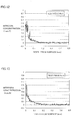
- Fig. 4 shows a graph compiling experimental results.
- the graph shown in Fig. 4 compiles the experimental results, with the tempering temperature on the axis of abscissas and the difference in cross sectional hardness (i.e., [the maximum value of the cross sectional hardness] - [the cross sectional hardness at a position with the depth of 1 mm from the uppermost surface subjected to the heat treatment]: also expressed as ⁇ HV) on the axis of ordinates.
- difference ⁇ HV in cross sectional hardness was maximum after the high-temperature tempering at the heating retention temperature of 500°C for the retention time of one hour.
- Difference ⁇ HV in cross sectional hardness at the heating retention temperature of 500°C had a value about double that of difference ⁇ HV in cross sectional hardness after the high-temperature tempering at the heating retention temperature of 300°C or 700°C. Accordingly, it is considered that the hardness after the tempering having a relatively high correlation with the nitrogen concentration is the hardness after the tempering at a heating retention temperature of about 500°C. Therefore, in an experiment below, measurement of the cross sectional hardness was performed on the test pieces subjected to high-temperature tempering at a heating retention temperature of 500°C for a retention time of one hour.
- each test piece having a composition shown in Table 1 was subjected to the heat treatment at the heating retention temperature of 500°C for the retention time of one hour as the high-temperature tempering, and thereafter a nitrogen concentration in each test piece was measured by the EPMA analysis as described with reference to Fig. 3 . Further, a cross sectional hardness in a depth direction of the test piece was measured in the cut-out end surface of test piece 12 shown in Fig. 3 . Then, relationship of a difference between a cross sectional hardness at a certain position in the depth direction and the cross sectional hardness at the position with the depth of 1 mm from the uppermost surface subjected to the heat treatment (hereinafter defined as a cross sectional hardness difference ( ⁇ HV)) was investigated.
- ⁇ HV cross sectional hardness difference
- Fig. 5 shows results thereof.
- the axis of abscissas represents the nitrogen concentration (unit: mass %)
- the axis of ordinates represents the cross sectional hardness difference ( ⁇ HV) (unit: Vickers hardness).
- the axis of abscissas represents the nitrogen concentration (unit: mass %), and the axis of ordinates represents cross sectional hardness difference ⁇ HV (unit: Vickers hardness).
- ⁇ HV unit: Vickers hardness
- Fig. 7 is a graph with cross sectional hardness difference ⁇ HV (unit: Vickers hardness) on the axis of abscissas and the nitrogen concentration (unit: mass %) on the axis of ordinates, plotting the data shown in Fig. 6 . From these data, an approximate equation expressing the relationship between the nitrogen concentration and the cross sectional hardness difference is determined. Fig. 7 also shows the approximate equation. As shown in Fig.
- nitrogen concentration mass % cross sectional hardness difference ⁇ HV ⁇ 0.00085 - 0.011 It is estimated from equation (1) that the nitrogen concentration at a position having a cross sectional hardness difference of, for example, 130 ( ⁇ HV) is 0.1 mass %.
- an inspection method for assuring that the nitrogen concentration in a ground uppermost surface (i.e., a final uppermost surface of the bearing part) is a predetermined value (for example, specifically, not less than 0.1 mass %) is proposed, and a component (bearing part) of a rolling bearing for which the nitrogen concentration is assured is provided based on the inspection method.
- the maximum distance between the depth position having the nitrogen concentration of 0.1 mass % and the depth position having the nitrogen concentration of 0.06 mass % is 40 ⁇ m. Accordingly, it is considered based on Fig. 8 and the like that the nitrogen concentration is not less than 0.1 mass % in a range from a position which is 40 ⁇ m closer to a surface side of the carbonitriding-treated part than the depth position having the nitrogen concentration of 0.06 mass %, to the surface.
- the cross sectional hardness difference ( ⁇ HV) at a certain depth position is not less than 80, it can be assured that the nitrogen concentration in a region 40 ⁇ m closer to the surface from the depth position is not less than 0.1 mass %. It is noted that the nitrogen concentration in a region 40 ⁇ m shifted to the surface side from the depth position having the nitrogen concentration of 0.06 mass % in each of four conditions shown in Fig. 8 is calculated to have a value shown in Table 2.
- Table 2 shows a nitridation time (carbonitriding treatment time), an undecomposed NH 3 volume fraction, and a nitrogen concentration in the ground uppermost surface corresponding to the nitrogen concentration in the region 40 ⁇ m shifted to the surface side from the depth position having the nitrogen concentration of 0.06 mass %, in each condition.
- the nitrogen concentration in the region is not less than 0.1 mass %.
- the inspection method (quality assurance method) to be proposed by the inventor of the present invention is to indicate that the nitrogen concentration before the high-temperature tempering at the heating retention temperature of 500°C for the retention time of one hour is performed, that is, the nitrogen concentration in a ground uppermost surface of an actual product, is not less than 0.1 mass %.
- nitride concentration distribution was measured for each of test pieces No. 3, No. 8, No. 9, and No.
- Table 3 shows, from the left, the test piece No., the nitrogen concentration (unit: mass %) in the region where the depth from the specimen surface was measured, the depth from the test piece surface to the region (unit: ⁇ m) before the high-temperature tempering was performed, the depth from the test piece surface to the region (unit: ⁇ m) after the high-temperature tempering was performed, the moving distance (unit: ⁇ m) of the region in the depth direction by the high-temperature tempering, and the average value (unit: ⁇ m) of the moving distances of the region for each nitrogen concentration.
- the nitrogen concentration is not less than 0.1 mass % from a region which is 40 ⁇ m closer to the surface side (i.e., shallower) than a region having a nitrogen concentration of 0.06 mass %, to the surface, it is necessary to consider the nitrogen moving distance described above due to the high-temperature tempering (tempering of 500°C ⁇ 1h) in order to assure that the nitrogen concentration in the ground uppermost surface before the high-temperature tempering (tempering of 500°C ⁇ 1h) is not less than 0.1 mass %.
- the maximum distance between the depth having the nitrogen concentration of 0.1 mass % and the depth having the nitrogen concentration of 0.06 mass % is 40 ⁇ m, and the nitrogen moving distance due to the high-temperature tempering (tempering of 500°C ⁇ 1h) is 30 ⁇ m, a summed distance (70 ⁇ m) of the maximum distance (40 ⁇ m) and the nitrogen moving distance (30 ⁇ m) should be considered.
- the nitrogen concentration at a position with a depth obtained by adding a grinding allowance (only for one surface) for the carbonitriding-treated bearing part to the summed distance is not less than 0.06 mass % (that is, if the cross sectional hardness difference after the high-temperature tempering (tempering of 500°C ⁇ 1h) is not less than 80), it can be assured that the nitrogen concentration in the ground uppermost surface before the high-temperature tempering (tempering of 500°C ⁇ 1h) is not less than 0.1 mass %.
- the present inspection method was applied to test pieces to determine whether each test piece passed or failed the inspection, and compare their actual measurement values of the nitrogen concentration.
- the test pieces shown in Table 1 were used as the test pieces.
- Table 4 shows, from the left column, the test piece No., the grinding allowance for one surface of each test piece (unit: ⁇ m), the cross sectional hardness difference ( ⁇ HV) as the difference between the cross sectional hardness at the position with the depth of [the grinding allowance + 70 ⁇ m] from the surface and the cross sectional hardness at the position 1 mm from the surface after the high-temperature tempering (tempering of 500°C ⁇ 1h), the result of pass/fail determination based on the present inspection method, and the actual measurement value of the nitrogen concentration (unit: mass %) at a position of the ground uppermost surface measured with an EPMA before the high-temperature tempering was performed.
- the present inspection method quality assurance method
- the present inspection method can be considered as a method appropriate for determining that the nitrogen concentration at the position of the ground uppermost surface is not less than 0.1 mass %.
- Figs. 9 to 18 each show an actual measurement value of nitrogen concentration distribution in each test piece before the high-temperature tempering (tempering of 500°C ⁇ 1h).
- the axis of abscissas represents the depth from the surface (unit: mm), and the axis of ordinates represents the nitrogen concentration (unit: mass %).
- the present invention is particularly advantageously applicable to carbonitriding-treated bearing part and bearing.
Abstract
Description
- The present invention relates to a bearing part, a bearing, and a method for inspecting a bearing part. More specifically, the present invention relates to a bearing part, a bearing, and a method for inspecting a bearing part subjected to carbonitriding treatment.
- It has been conventionally qualitatively known that carbonitriding treatment is effective to extend rolling contact fatigue life of a rolling bearing (see for example "Rolling Fatigue Characteristics of Carburized or Carbonitrided 1% Cr Steel at Elevated Temperatures" by Hyojiro Kurabe et al., Iron and Steel, vol. 11, (1967), p. 1305 (hereinafter referred to as Non-Patent Literature 1) and Japanese Patent No.
2962817 2009-229288 - Accordingly, if it is possible to provide a rolling bearing part which is quality-assured to have a nitrogen concentration of not less than 0.1 mass % in a ground uppermost surface of a carbonitrided part, safety of a rolling bearing is ensured more reliably, and safety of mechanical equipment using the rolling bearing is improved, providing a great social advantage as a result.
- At present, however, a nitrogen concentration in steel can be quantified only by a method performed using analysis equipment such as an EPMA (Electron Probe Micro Analyzer) and a GDS (Glow Discharge Spectrometer), and such measurement requires a great number of man-hours. Therefore, if a method using analysis equipment as described above is adopted as an inspection method for quality assurance, the rolling bearing becomes very expensive, which is not practical.
- In addition, a method for qualitatively evaluating the degree of nitridation by utilizing the characteristics of nitrogen which has entered steel that "the hardness after high-temperature tempering is higher than that of a non-nitrided portion" is described, for example, in "Effects of Nitrogen Content on Microstructure and Resistance to Softening during Tempering of Carbo-Nitrided Chromium Alloy Steels" by Youichi Watanabe et al., Heat Treatment, vol. 40, (2000), p. 18 (hereinafter referred to as Non-Patent Literature 2), and the like.
-
- PTL 1:
- Japanese Patent No.
2962817 - PTL 2:
- Japanese Patent Laying-Open No.
2009-229288 -
- NPL 1: "Rolling Fatigue Characteristics of Carburized or Carbonitrided 1% Cr Steel at Elevated Temperatures" by Hyojiro Kurabe et al., Iron and Steel, vol. 11, (1967), p. 1305
- NPL 2: "Effects of Nitrogen Content on Microstructure and Resistance to Softening during Tempering of Carbo-Nitrided Chromium Alloy Steels" by Youichi Watanabe et al., Heat Treatment, vol. 40, (2000), p. 18
- It is also conceivable to qualitatively evaluate a depth of nitridation of a carbonitriding-treated bearing part by measuring distribution of a cross sectional hardness of the bearing part after high-temperature tempering, utilizing the characteristics of nitrogen in steel as described above.
- However, with a method as described above, a nitrogen concentration of a carbonitriding-treated member (for example, a bearing part) has not been quantitatively assured. In order to economically and reliably improve safety of mechanical equipment using a bearing part and a bearing as described above, there have been demands for an inspection method which quantitatively assures a nitrogen concentration in a simple way, as well as for a bearing part and a bearing for which such a nitrogen concentration is quantitatively assured.
- The present invention has been made to solve aforementioned problems, and one object of the present invention is to provide an inspection method which quantitatively and simply assures a nitrogen concentration in a carbonitriding-treated bearing part, and a bearing part and a bearing for which a nitrogen concentration is quantitatively assured.
- A bearing part in accordance with the present invention is a bearing part made of JIS standard SUJ2 and having a carbonitrided layer formed in a surface thereof, wherein, after heat treatment at a heating temperature of 500°C for a retention time of one hour is performed, a Vickers hardness at a position with a depth of 30 µm from the surface is higher than a Vickers hardness at a core portion, which is a region where the carbonitrided layer is not formed in a thickness direction of the bearing part, by not less than 130 HV.
- As described later, the inventor has obtained fmdings that, in the bearing part made of JIS standard SUJ2, there is a correlation between a Vickers hardness and a nitrogen concentration in the carbonitrided layer subjected to heat treatment under conditions as described above, and that nitrogen distribution is shifted toward an inner side in the thickness direction by a predetermined distance (30 µm) due to the heat treatment. Thus, the Vickers hardness at the position with the depth of 30 µm from the surface subjected to heat treatment as described above is higher than that in a region not subjected to carbonitriding treatment by a predetermined value, in accordance with the nitrogen concentration at the position (i.e., the nitrogen concentration in the surface of the bearing part before the heat treatment is performed). Therefore, by setting a reference value for an improvement amount of the Vickers hardness beforehand in accordance with a designed nitrogen concentration in the surface of the bearing part before the heat treatment is performed (for example, if the designed nitrogen concentration is 0.1 mass %, the reference value for the improvement amount of the Vickers hardness is set to 130 HV), and determining whether or not a difference between a measurement value of the Vickers hardness at the position with the depth of 30 µm from the surface subjected to the heat treatment and a measurement value of the Vickers hardness at the core portion, which is a region other than the carbonitrided layer, satisfies the reference value (i.e., whether or not the difference is more than the reference value), whether or not the nitrogen concentration in the surface of the bearing part is not less than the designed nitrogen concentration can be inspected. As a result, the bearing part in accordance with the present invention can assure that the nitrogen concentration in the surface before the heat treatment is not less than 0.1 mass %.
- Preferably, in the bearing part, after the heat treatment at the heating temperature of 500°C for the retention time of one hour is performed, a Vickers hardness at a position with a depth of 70 µm from the surface is higher than the Vickers hardness at the core portion by not less than 80 HV. Here, the maximum distance in a depth direction between a position having a nitrogen concentration of 0.1 mass % and a position having a nitrogen concentration of 0.06 mass % in the carbonitrided layer of the bearing part is 40 µm, as described later. Therefore, if a difference between a Vickers hardness at a region located further closer to the inner side in the thickness direction by 40 µm in addition to the distance for which the nitrogen distribution is shifted (30 µm) toward the inner side in the thickness direction due to the heat treatment and the Vickers hardness at the core portion is not less than 80 HV (i.e., if the region has a nitrogen concentration of not less than 0.06 mass %), it can be reliably assured that the nitrogen concentration in the surface of the carbonitrided layer before the heat treatment is not less than 0.1 mass %.
- Further, as described later, the difference between the Vickers hardnesses at a region within the carbonitrided layer and at the core portion, and the nitrogen concentration have a linear relationship when the nitrogen concentration is in a range of about 0 to 0.1 mass %. Therefore, if the nitrogen concentration used for determination is set to, for example, 0.06 mass %, which is close to substantially the center of the range exhibiting the linear relationship, a relatively good correlation between the difference in the Vickers hardness and the nitrogen concentration is obtained, and thus correctness of the determination can be improved.
- A bearing part in accordance with the present invention is a bearing part made of JIS standard SUJ2 and having a carbonitrided layer formed in a surface thereof, wherein, after heat treatment at a heating temperature of 500°C for a retention time of one hour is performed, a Vickers hardness at a position with a depth of 70 µm from the surface is higher than a Vickers hardness at a core portion, which is a region where the carbonitrided layer is not formed in a thickness direction of the bearing part, by not less than 80 HV.
- Here, the inventor has obtained findings that there is a correlation between the Vickers hardness and the nitrogen concentration in the carbonitrided layer subjected to heat treatment under conditions as described above, that the nitrogen distribution is shifted toward the inner side in the thickness direction by a certain distance (30 µm) due to the heat treatment, and that, as described above, the maximum distance in the depth direction between the position having the nitrogen concentration of 0.1 mass % and the position having the nitrogen concentration of 0.06 mass % in the carbonitrided layer of the bearing part is 40 µm. Thus, the Vickers hardness at the position with the depth of 30 µm from the surface subjected to heat treatment as described above is higher than that in a region not subjected to carbonitriding treatment by a predetermined value, in accordance with the nitrogen concentration at the position (i.e., the nitrogen concentration in the surface of the bearing part before the heat treatment is performed).
- In addition, as described later, a difference between a Vickers hardness at a region having a nitrogen concentration of 0.06 mass % and the Vickers hardness at the core portion is 80 HV, and the absolute value of the difference is increased with an increase in the nitrogen concentration. Accordingly, if the above difference related to the Vickers hardness at the position with the depth of 70 µm from the surface is not less than 80 HV as described above, it is recognized that the nitrogen concentration at the position is not less than 0.06 mass %. Further, since the nitrogen concentration tends to be increased toward the surface side from the position, and the distance between the position having the nitrogen concentration of 0.1 mass % and the position having the nitrogen concentration of 0.06 mass % is 40 µm at a maximum, it is recognized that the nitrogen concentration at the
position 30 µm from the surface is not less than 0.1 mass %. - Thus, the nitrogen concentration in the surface of the bearing part before the heat treatment can be verified from the difference between the Vickers hardness at the position with the depth of 70 µm from the surface and the Vickers hardness at the core portion. As a result, the bearing part in accordance with the present invention can assure that the nitrogen concentration in the surface before the heat treatment is not less than 0.1 mass %.
- In the bearing part, the nitrogen concentration in the surface of the carbonitrided layer may be not less than 0.1 mass %. In this case, the life of the bearing part can be reliably extended.
- In the bearing part, the carbonitrided layer may be formed by carbonitriding treatment performed at a treatment temperature in a temperature range of not less than a point A1 and not more than a point Acm. In this case, the carbonitrided layer can be reliably formed in the bearing part. Here, point A1 refers to a point corresponding to a temperature at which the structure of steel starts transformation from ferrite to austenite when the steel is heated. In addition, point Acm refers to a point corresponding to a temperature at which cementite in hypereutectoid steel is completely dissolved during heating.
- In the bearing part, the carbonitrided layer may be formed by carbonitriding treatment performed at a treatment temperature in a temperature range of, for example, not less than 840°C and not more than 860°C. In this case, the carbonitrided layer can be reliably formed in the bearing part.
- A bearing in accordance with the present invention is a bearing manufactured using the bearing part described above. With such a configuration, a bearing with a reliably extended life when compared with a bearing using a non-nitrided bearing part can be obtained by quantitatively assuring the nitrogen concentration in the surface of the carbonitrided layer.
- A method for inspecting a bearing part in accordance with the present invention includes the steps of: preparing a bearing part made of JIS standard SUJ2 and having a carbonitrided layer formed in a surface thereof; performing heat treatment on the bearing part; measuring, after the heat treatment, a first Vickers hardness at a position with a summed depth from the surface, the summed depth being obtained by adding a first distance to a grinding allowance for the surface, and a second Vickers hardness at a core portion, which is a region where the carbonitrided layer is not formed in a thickness direction of the bearing part; and determining whether or not the first Vickers hardness is higher than the second Vickers hardness by a reference value.
- With such a configuration, the nitrogen concentration in the surface of the bearing part can be quantitatively assured based on the inventor's new findings that, in the bearing part made of JIS standard SUJ2, there is a correlation between the Vickers hardness and the nitrogen concentration in the carbonitrided layer subjected to heat treatment under predetermined conditions, and that the nitrogen distribution is shifted toward the inner side in the thickness direction by a predetermined distance due to the heat treatment.
- In the method for inspecting a bearing part described above, the heat treatment may be heat treatment at a heating temperature of 500°C for a retention time of one hour, the first distance may be 30 µm, and the reference value may be 130 HV.
- In this case, whether or not the nitrogen concentration in the surface of the bearing part before the heat treatment is not less than 0.1 mass % can be determined based on the inventor's findings that there is a correlation between the Vickers hardness and the nitrogen concentration after heat treatment as described above is performed, and that the nitrogen distribution is shifted toward the inner side in the thickness direction by about 30 µm due to the heat treatment.
- In the method for inspecting a bearing part described above, the heat treatment may be heat treatment at a heating temperature of 500°C for a retention time of one hour, the first distance may be 70 µm, and the reference value may be 80 HV.
- In the inspection method described above, the nitrogen concentration confirmed in the surface of the carbonitrided layer in the bearing part may be not less than 0.1 mass %.
- In the inspection method described above, the carbonitrided layer may be formed by carbonitriding treatment performed at a treatment temperature in a temperature range of not less than a point A1 and not more than a point Acm.
- In the inspection method described above, the carbonitrided layer may be formed by carbonitriding treatment performed at a treatment temperature in a temperature range of not less than 840°C and not more than 860°C.
- According to the present invention, a bearing part in which a nitrogen concentration in a surface thereof is not less than 0.1 mass % can be reliably provided.
-
-
Fig. 1 is a schematic cross sectional view showing an embodiment of a bearing in accordance with the present invention. -
Fig. 2 is a flowchart for illustrating a method for inspecting a bearing part in accordance with the present invention. -
Fig. 3 is a schematic view showing a specimen for measuring a nitrogen concentration. -
Fig. 4 is a graph showing relationship between a tempering temperature and a cross sectional hardness difference ΔHV as a difference between a maximum value of Vickers hardness and a Vickers hardness at a position with a depth of 1 mm. -
Fig. 5 is a graph showing relationship between the nitrogen concentration and the cross sectional hardness difference. -
Fig. 6 is a graph showing relationship between the nitrogen concentration and the cross sectional hardness difference when the nitrogen concentration is in a range of not more than 0.1 mass %. -
Fig. 7 is a graph showing relationship between the cross sectional hardness difference and the nitrogen concentration. -
Fig. 8 is a graph showing relationship between a depth from a surface and a nitrogen concentration in each specimen. -
Fig. 9 is a graph showing relationship between a depth from a surface and a nitrogen concentration in a test piece after heat treatment is finished. -
Fig. 10 is a graph showing relationship between a depth from a surface and a nitrogen concentration in a test piece after heat treatment is finished. -
Fig. 11 is a graph showing relationship between a depth from a surface and a nitrogen concentration in a test piece after heat treatment is finished. -
Fig. 12 is a graph showing relationship between a depth from a surface and a nitrogen concentration in a test piece after heat treatment is finished. -
Fig. 13 is a graph showing relationship between a depth from a surface and a nitrogen concentration in a test piece after heat treatment is finished. -
Fig. 14 is a graph showing relationship between a depth from a surface and a nitrogen concentration in a test piece after heat treatment is finished. -
Fig. 15 is a graph showing relationship between a depth from a surface and a nitrogen concentration in a test piece after heat treatment is finished. -
Fig. 16 is a graph showing relationship between a depth from a surface and a nitrogen concentration in a test piece after heat treatment is finished. -
Fig. 17 is a graph showing relationship between a depth from a surface and a nitrogen concentration in a test piece after heat treatment is finished. -
Fig. 18 is a graph showing relationship between a depth from a surface and a nitrogen concentration in a test piece after heat treatment is finished. - Hereinafter, an embodiment of the present invention will be described with reference to the drawings. In the drawings below, identical or corresponding parts will be designated by the same reference numerals, and the description thereof will not be repeated.
- Referring to
Fig. 1 , abearing 10 includes an annularouter race 2, an annularinner race 1 arranged insideouter race 2, and a plurality ofballs 3 as rolling elements arranged betweenouter race 2 andinner race 1 and held in anannular holder 4,inner race 1,outer race 2, andballs 3 being made of JIS standard JUS2. Anouter raceway surface 2A is formed in an inner peripheral surface ofouter race 2, and aninner raceway surface 1A is formed in an outer peripheral surface ofinner race 1.Outer race 2 andinner race 1 are arranged such thatinner raceway surface 1A andouter raceway surface 2A face each other. Further, the plurality ofballs 3 come into contact withinner raceway surface 1A andouter raceway surface 2A atball rolling surfaces 3A as their surfaces, are circumferentially arranged at a predetermined pitch byholder 4, and thereby held on an annular raceway in a freely rolling manner. With the above configuration,outer race 2 andinner race 1 of bearing 10 are relatively rotatable with respect to each other. At leastouter raceway surface 2A ofouter race 2 is a region where a carbonitrided layer is formed.Inner raceway surface 1A ofinner race 1 is also a region where a carbonitrided layer is formed. Further, a carbonitrided layer is formed in the surface of eachball 3. Furthermore, a nitrogen concentration in surfaces of the carbonitrided layers ininner race 1,outer race 2, andballs 3 is not less than 0.1 mass %. - In addition, from a different viewpoint,
inner race 1,outer race 2, andballs 3 as bearing parts in accordance with the present invention described above are each a bearing part made of JIS standard SUJ2 and having a carbonitrided layer formed in a surface thereof, wherein, after heat treatment at a heating temperature of 500°C for a retention time of one hour (i.e., high-temperature tempering) is performed, a Vickers hardness at a position with a depth of 30 µm from the surface is higher than a Vickers hardness at a core portion, which is a region where the carbonitrided layer is not formed in a thickness direction of the bearing part (inner race 1,outer race 2, ball 3), by not less than 130 HV. Such a configuration can assure that the nitrogen concentration in the surface in the bearing part is not less than 0.1 mass % as described later, and can extend the life of a bearing using the bearing part as a result. - Preferably, in the bearing part (for example,
inner race 1,outer race 2, ball 3), after the heat treatment at the heating temperature of 500°C for the retention time of one hour is performed, a Vickers hardness at a position with a depth of 70 µm from the surface is higher than the Vickers hardness at the core portion by not less than 80 HV. Such a configuration can reliably assure that the nitrogen concentration in the surface of the carbonitrided layer before the heat treatment is not less than 0.1 mass %. - Further, as described later, a difference between the Vickers hardnesses at a region within the carbonitrided layer and at the core portion, and the nitrogen concentration have a linear relationship when the nitrogen concentration is in a range of about 0 to 0.1 mass %. Therefore, if the nitrogen concentration used for determination is set to a value close to substantially the center of the range exhibiting the linear relationship (for example, 0.06 mass %), a relatively good correlation between the difference in the Vickers hardness and the nitrogen concentration is obtained, and thus correctness of the determination can be improved.
- In addition, the bearing part (
inner race 1,outer race 2, ball 3) in accordance with the present invention is a bearing part made of JIS standard SUJ2 and having a carbonitrided layer formed in a surface thereof, wherein, after heat treatment at a heating temperature of 500°C for a retention time of one hour is performed, a Vickers hardness at a position with a depth of 70 µm from the surface is higher than a Vickers hardness at a core portion, which is a region where the carbonitrided layer is not formed in a thickness direction of the bearing part, by not less than 80 HV. Such a configuration can reliably assure that the nitrogen concentration in the surface of the carbonitrided layer before the heat treatment is not less than 0.1 mass %, as described later. - In the bearing part (
inner race 1,outer race 2, ball 3), the nitrogen concentration in the surface of the carbonitrided layer, for example in the rolling surface, is not less than 0.1 mass %. In this case, the life of the bearing part (inner race 1,outer race 2, ball 3) can be reliably extended. - In the bearing part such as
inner race 1,outer race 2, andball 3, the carbonitrided layer may be formed by carbonitriding treatment performed at a treatment temperature in a temperature range of not less than a point A1 and not more than a point Acm. In this case, the carbonitrided layer can be reliably formed in the bearing part such asinner race 1,outer race 2, andball 3. - In the bearing part such as
inner race 1,outer race 2, andball 3, the carbonitrided layer may be formed by carbonitriding treatment performed at a treatment temperature in a temperature range of, for example, not less than 840°C and not more than 860°C. In this case, the carbonitrided layer can be reliably formed in the bearing part such asinner race 1,outer race 2, andball 3. -
Bearing 10 in accordance with the present invention is a bearing manufactured using the bearing part such asinner race 1,outer race 2, andball 3. With such a configuration, a bearing with a reliably extended life when compared with a bearing using a non-nitrided bearing part can be obtained by quantitatively assuring the nitrogen concentration in the surface of the carbonitrided layer. - The nitrogen concentration in the surface of the bearing part such as
inner race 1,outer race 2, andball 3 constituting bearing 10 shown inFig. 1 can be inspected by an inspection method as described below. Hereinafter, a method for inspecting the bearing part in accordance with the present invention will be described with reference toFig. 2 . - As shown in
Fig. 2 , in the method for inspecting the bearing part in accordance with the present invention, a sample as the bearing part such asinner race 1,outer race 2, andball 3 subjected to carbonitriding treatment and the like is prepared to perform the step of performing high-temperature tempering on the sample (S10). In this step (S10), a tempering temperature (heating retention temperature) can be set to, for example, not less than 300°C and not more than 700°C, preferably not less than 400°C and not more than 600°C, and more preferably 500°C, and a tempering time (retention time) can be set to, for example, one hour. By performing such heat treatment, the carbonitrided layer has a Vickers hardness higher than a Vickers hardness in a region other than the carbonitrided layer. - Next, the step of measuring a cross sectional hardness of the sample (S20) is performed as shown in
Fig. 2 . Specifically, for example, if inner race 1 (seeFig. 1 ) is used as a sample, a test piece is cut out of the sample, and a cross sectional hardness (Vickers hardness) of the test piece is measured at a predetermined position in the thickness direction from an outer diameter side toward an inner diameter side. The hardness may be measured, for example, at twopositions 30 µm and 1 mm from a surface (surface on the outer diameter side), or two positions 70 µm and 1 mm from the surface, or threepositions 30 µm, 70 µm, and 1 mm from the surface. - Next, the step of calculating a difference in cross sectional hardness (S30) is performed as shown in
Fig. 2 . Specifically, a difference between the Vickers hardness at theposition 1 mm from the surface corresponding to the core portion as the region other than the carbonitrided layer and the Vickers hardness at theposition 30 µm or 70 µm from the surface is calculated. - Next, the step of comparing the difference in cross sectional hardness with a reference value (S40) is performed. Specifically, the difference in cross sectional hardness calculated in the above step (S30) is compared with a predetermined reference value to determine whether or not the value of the difference satisfies the reference value (i.e., whether or not the value of the difference is not less than the reference value). If the value of the difference satisfies the reference value, it can be confirmed that the nitrogen concentration in the surface before the heat treatment (high-temperature tempering) is performed on the sample is a predetermined value (for example, 0.1 mass %).
- To summarize the characteristic feature of the method for inspecting the bearing part described above, the inspection method includes the steps of: preparing a bearing part (for example,
inner race 1,outer race 2, ball 3) made of JIS standard SUJ2 and having a carbonitrided layer formed in a surface thereof; performing heat treatment on the bearing part (S10); measuring, after the heat treatment, a first Vickers hardness at a position with a summed depth from the surface, the summed depth being obtained by adding a first distance to a grinding allowance for the surface, and a second Vickers hardness at a core portion, which is a region where the carbonitrided layer is not formed in a thickness direction of the bearing part (S20); and determining whether or not the first Vickers hardness is higher than the second Vickers hardness by a reference value (S30, S40). - Thereby, the nitrogen concentration in the surface of the bearing part such as
inner race 1,outer race 2, andball 3 can be quantitatively assured based on the inventor's new findings that, in the bearing part such asinner race 1 made of JIS standard SUJ2, there is a correlation between the Vickers hardness and the nitrogen concentration in the carbonitrided layer subjected to heat treatment under predetermined conditions, and that nitrogen distribution is shifted toward an inner side in the thickness direction by a predetermined distance due to the heat treatment, as described later. - In the method for inspecting the bearing part described above, the heat treatment may be heat treatment at a heating temperature of 500°C for a retention time of one hour, the first distance may be 30 µm, and the reference value may be 130 HV.
- In this case, whether or not the nitrogen concentration in the surface of the bearing part before the heat treatment is not less than 0.1 mass % can be determined based on the inventor's findings that there is a correlation between the Vickers hardness and the nitrogen concentration after heat treatment (high-temperature tempering) as described above is performed, and that the nitrogen distribution is shifted toward the inner side in the thickness direction by about 30 µm due to the heat treatment.
- In the method for inspecting the bearing part described above, the heat treatment may be heat treatment at a heating temperature of 500°C for a retention time of one hour, the first distance may be 70 µm, and the reference value may be 80 HV. In this case, whether or not the nitrogen concentration in the surface of the bearing part before the heat treatment is not less than 0.1 mass % can be determined with higher accuracy.
- In the inspection method described above, the nitrogen concentration confirmed in the surface of the carbonitrided layer in the bearing part is not less than 0.1 mass %. In this case, since the nitrogen concentration in the surface is at a level that can achieve the effect of extending the life of the bearing part, the bearing part determined by the inspection method as passing the inspection can reliably achieve the effect of extending the life.
- In the inspection method described above, the carbonitrided layer may be formed by carbonitriding treatment performed at a treatment temperature in a temperature range of not less than a point A1 and not more than a point Acm. Further, in the inspection method described above, the carbonitrided layer may be formed by carbonitriding treatment performed at a treatment temperature in a temperature range of not less than 840°C and not more than 860°C.
- Hereinafter, in order to actually apply the inspection method in accordance with the present invention described above to a bearing part made of JIS standard SUJ2, the positions for measuring hardnesses and the reference value were determined through a procedure as described below.
- Firstly, it is necessary to determine the heating retention temperature and the retention time in the high-temperature tempering which have a high correlation with the nitrogen concentration. Since transformation by the high-temperature tempering is a thermally-activated process, increasing the heating retention temperature and increasing the retention time have the same meaning, and it is considered meaningless to use the both as variables. Thus, in the present specification, the heating retention temperature suitable for an inspection was determined as described below, by setting the retention time to a fixed time (one hour) and changing the heating retention temperature to 300°C, 400°C, 500°C, 600°C, and 700°C to investigate a heating retention temperature at which a difference in hardness was clearest.
- Further, it is considered that a difference in hardenability and a difference in cooling rate during hardening due to a difference in chemical components in each material may affect a hardness after the hardening and also may affect a hardness after the high-temperature tempering. Thus, as described above, the absolute value itself of a cross sectional hardness is not used as an indicator for the inspection, but a hardness difference between a hardness at a non-nitrided position deep from a surface layer (core portion) (here, for example, a hardness at a depth of 1 mm from an uppermost surface subjected to heat treatment) and a hardness at a position with a certain depth within a nitrided region was adopted as an indicator for the present inspection method.
- Table 1 shows chemical components of test pieces subjected to an investigation. The materials were all made of JIS standard SUJ2, and subjected to carbonitriding treatment in various heat treatment furnaces and under various heat treatment atmospheres. It is noted that the carbonitriding treatment temperature was included in a temperature range of not less than 840°C and not more than 860°C.
[Table 1] Test Piece No. Chemical Components (mass %) C Si Mn Ni Cr Mo Cu O* 1 1.03 0.25 0.35 0.01 1.50 0 0.01 4 2 unknown 3 0.98 0.27 0.47 0.05 1.45 0.02 0.10 6 4 1.00 0.27 0.35 0.02 1.51 0 0.01 7 5 1.01 0.24 0.35 0.01 1.49 0 0.01 3 6 0.99 0.26 0.37 0.02 1.44 0 0.01 5 7 unknown 8 0.98 0.25 0.34 0.07 1.43 0.03 0.10 6 9 0.98 0.25 0.34 0.07 1.43 0.03 0.10 6 10 0.98 0.25 0.34 0.07 1.43 0.03 0.10 6 *ppm - Specifically, test piece No. 1 was subjected to treatment under conditions of a carbonitriding treatment temperature of 850°C, a treatment time of 120 minutes (min.) (hereinafter expressed as "850°C×120 min."), an undecomposed NH3 fraction of 0.2 vol. %, and a carbon activity of 0.9. Test piece No. 2 was subjected to treatment under conditions of 840°Cx70 min., an undecomposed ammonia fraction of 0.1 vol. %, and a carbon activity of 0.85. Test piece No. 3 was subjected to treatment under conditions of 850°C×120 min., an undecomposed ammonia fraction of 0.1 vol. %, and a carbon activity of 0.9. Test piece No. 4 was subjected to treatment under conditions of 850°Cx90 min., an undecomposed ammonia fraction of 0.1 vol. %, and a carbon activity of 0.9. Test piece No. 5 was subjected to treatment under conditions of 850°Cx90 min., an undecomposed ammonia fraction of 0.1 vol. %, and a carbon activity of 0.9.
- In addition, test piece No. 6 was subjected to treatment under conditions of 850°Cx90 min., an undecomposed ammonia fraction of 0.13 vol. %, and a carbon activity of 0.9. Test piece No. 7 was subjected to treatment under conditions of 850°C×150 min., an undecomposed ammonia fraction of 0.1 vol. %, and a carbon activity of 0.85. Test piece No. 8 was subjected to treatment under conditions of 850°C×150 min., an undecomposed ammonia fraction of 0.25 vol. %, and a carbon activity of 0.9. Test piece No. 9 was subjected to treatment under conditions of 850°C×180 min., an undecomposed ammonia fraction of 0.3 vol. %, and a carbon activity of 0.95. Test piece No. 10 was subjected to treatment under conditions of 850°Cx90 min., an undecomposed ammonia fraction of 0.2 vol. %, and a carbon activity of 0.9.
- In order to investigate correlation between a cross sectional hardness and a nitrogen concentration of a sample subjected to the high-temperature tempering, it is necessary to measure nitrogen concentration distribution in the sample (steel). Line analysis with an EPMA was used to measure the nitrogen concentration in the steel subjected to the carbonitriding treatment. Quantification was performed by analyzing a calibration test piece having a known nitrogen concentration and using a calibration curve thereof.
Fig. 3 shows a schematic view of a sample used for EPMA analysis and a measurement method. - It is assumed that, for example, inner race 1 (see
Fig. 1 ) is used as asample 11 as shown inFig. 3 . Forsample 11, a nitrogen concentration insample 11 subjected to the carbonitriding treatment was measured. Specifically, atest piece 12 as shown inFig. 3 was cut out ofsample 11, and line analysis with an EPMA was performed on a cut-out end surface at a central portion in a height direction of test piece 12 (i.e., at a position with a half width) along a direction from asurface 13 on an outer diameter side to asurface 14 on an inner diameter side of the test piece. - Hardness was measured at the cut-out end surface subjected to the EPMA analysis in the test piece described above in (1-3). As a measuring method, Vickers hardness measurement was performed using a micro Vickers hardness tester.
- In order to search for a tempering temperature (heating retention temperature) having a high correlation with the nitrogen concentration, the test pieces subjected to the carbonitriding treatment were subjected to tempering at a heating temperature of 180°C for a retention time of two hours, and thereafter subjected to five types of high-temperature tempering at heating retention temperatures of 300°C, 400°C, 500°C, 600°C, and 700°C for a retention time of one hour. The high-temperature tempering was performed in an air atmosphere. Then, cross sectional hardnesses of the test pieces treated under the respective conditions for the high-temperature tempering were measured. Here, measurement was performed on test pieces No. 8 and No. 9 which were under carbonitriding treatment conditions considered to cause a large amount of nitrogen to enter the test pieces.
-
Fig. 4 shows a graph compiling experimental results. The graph shown inFig. 4 compiles the experimental results, with the tempering temperature on the axis of abscissas and the difference in cross sectional hardness (i.e., [the maximum value of the cross sectional hardness] - [the cross sectional hardness at a position with the depth of 1 mm from the uppermost surface subjected to the heat treatment]: also expressed as ΔHV) on the axis of ordinates. As can be seen fromFig. 4 , difference ΔHV in cross sectional hardness was maximum after the high-temperature tempering at the heating retention temperature of 500°C for the retention time of one hour. Difference ΔHV in cross sectional hardness at the heating retention temperature of 500°C had a value about double that of difference ΔHV in cross sectional hardness after the high-temperature tempering at the heating retention temperature of 300°C or 700°C. Accordingly, it is considered that the hardness after the tempering having a relatively high correlation with the nitrogen concentration is the hardness after the tempering at a heating retention temperature of about 500°C. Therefore, in an experiment below, measurement of the cross sectional hardness was performed on the test pieces subjected to high-temperature tempering at a heating retention temperature of 500°C for a retention time of one hour. - Here, each test piece having a composition shown in Table 1 was subjected to the heat treatment at the heating retention temperature of 500°C for the retention time of one hour as the high-temperature tempering, and thereafter a nitrogen concentration in each test piece was measured by the EPMA analysis as described with reference to
Fig. 3 . Further, a cross sectional hardness in a depth direction of the test piece was measured in the cut-out end surface oftest piece 12 shown inFig. 3 . Then, relationship of a difference between a cross sectional hardness at a certain position in the depth direction and the cross sectional hardness at the position with the depth of 1 mm from the uppermost surface subjected to the heat treatment (hereinafter defined as a cross sectional hardness difference (ΔHV)) was investigated.Fig. 5 shows results thereof. InFig. 5 , the axis of abscissas represents the nitrogen concentration (unit: mass %), and the axis of ordinates represents the cross sectional hardness difference (ΔHV) (unit: Vickers hardness). It has been found fromFig. 5 that, when the nitrogen concentration is in a range of more than 0 and not more than 0.1 mass %, the correlation between the nitrogen concentration and the cross sectional hardness difference is strong, whereas when the nitrogen concentration is in a range of more than 0.1 mass %, the correlation between the nitrogen concentration and the cross sectional hardness difference is relatively weak. This is considered to be because incomplete hardening may occur in a region with a high nitrogen concentration, and nitrogen dissolved in the test piece does not necessarily contribute to a reduction in the decomposition rate of martensite. - Specifically, it is considered that data represented as dots surrounded by dashed lines in
Fig. 5 are caused by a reduction in hardness due to occurrence of incomplete hardening. With these data removed, the relationship between the nitrogen concentration and the cross sectional hardness difference in the range of 0 to 0.1 mass % was extracted and compiled intoFig. 6 . - In the graph shown in
Fig. 6 , the axis of abscissas represents the nitrogen concentration (unit: mass %), and the axis of ordinates represents cross sectional hardness difference ΔHV (unit: Vickers hardness). When a correlation coefficient between the nitrogen concentration and the cross sectional hardness difference is calculated based on data of the graph shown inFig. 6 , a high correlation coefficient of 0.95 is obtained therebetween. Accordingly, it is considered that the nitrogen concentration can be predicted from the cross sectional hardness difference if the nitrogen concentration is in the range of 0 to 0.1 mass %. -
Fig. 7 is a graph with cross sectional hardness difference ΔHV (unit: Vickers hardness) on the axis of abscissas and the nitrogen concentration (unit: mass %) on the axis of ordinates, plotting the data shown inFig. 6 . From these data, an approximate equation expressing the relationship between the nitrogen concentration and the cross sectional hardness difference is determined.Fig. 7 also shows the approximate equation. As shown inFig. 7 , an experimental equation for determining the nitrogen concentration from the value of the cross sectional hardness difference is expressed by the following equation (1):
It is estimated from equation (1) that the nitrogen concentration at a position having a cross sectional hardness difference of, for example, 130 (ΔHV) is 0.1 mass %. - Here, for a rolling surface as a surface of a region where a carbonitrided layer is formed in the bearing part, an inspection method (quality assurance method) for assuring that the nitrogen concentration in a ground uppermost surface (i.e., a final uppermost surface of the bearing part) is a predetermined value (for example, specifically, not less than 0.1 mass %) is proposed, and a component (bearing part) of a rolling bearing for which the nitrogen concentration is assured is provided based on the inspection method. Accordingly, if an inspection based on the above inspection method is performed after the carbonitriding treatment and then finishing grinding is performed on the rolling surface of the bearing part, it is only necessary as a direct quality assurance method that the cross sectional hardness difference at a position with a depth considering a grinding allowance for the rolling surface is not less than 130, based on equation (1).
- However, as can be seen from
Fig. 5 , when the nitrogen concentration is more than 0.1 mass %, the correlation between the cross sectional hardness difference and the nitrogen concentration is drastically reduced. Thus, if the nitrogen concentration of 0.1 mass % is used as a standard for the above inspection (quality assurance standard), there is a possibility that an error is likely to occur in an inspection result. Therefore, a nitrogen concentration of 0.06 mass %, which is an approximately central value in the effective range of the nitrogen concentration in the graph shown inFig. 7 , is adopted here as a quality assurance standard. In this case, according to equation (1), it is estimated that the nitrogen concentration at a position having a cross sectional hardness difference of 80 is 0.06 mass %. - According to a nitrogen concentration distribution prediction equation (see "Nitrogen Concentration Distribution Prediction in SUJ2 Subjected to Carbonitriding Treatment" by Chikara Ohki, Iron and Steel, vol. 93, (2007), p. 220), practical nitrogen concentration distribution in a carbonitriding-treated part made of JIS standard SUJ2 is considered to be within the range shown in
Fig. 8 . In the graph shown inFig. 8 , the axis of abscissas represents a depth from the surface of the carbonitriding-treated part (unit: mm), and the axis of ordinates represents the nitrogen concentration (unit: mass %). It has been found fromFig. 8 that the distance between a depth position having a nitrogen concentration of 0.06 mass % and a depth position having a nitrogen concentration of 0.1 mass % falls within a range of not less than 15 µm and not more than 40 µm as a practical range. - Thus, the maximum distance between the depth position having the nitrogen concentration of 0.1 mass % and the depth position having the nitrogen concentration of 0.06 mass % (i.e., having a cross sectional hardness difference of 80) is 40 µm. Accordingly, it is considered based on
Fig. 8 and the like that the nitrogen concentration is not less than 0.1 mass % in a range from a position which is 40 µm closer to a surface side of the carbonitriding-treated part than the depth position having the nitrogen concentration of 0.06 mass %, to the surface. Therefore, if the cross sectional hardness difference (ΔHV) at a certain depth position is not less than 80, it can be assured that the nitrogen concentration in aregion 40 µm closer to the surface from the depth position is not less than 0.1 mass %. It is noted that the nitrogen concentration in aregion 40 µm shifted to the surface side from the depth position having the nitrogen concentration of 0.06 mass % in each of four conditions shown inFig. 8 is calculated to have a value shown in Table 2.[Table 2] Nitridation Time (min) Undecomposed NH3 Volume Fraction (vol. %) Nitrogen Concentration in Ground Uppermost Surface (mass %) 60 0.05 0.14 180 0.05 0.11 60 0.2 or more 0.20 180 0.2 or more 0.12 - It is noted that Table 2 shows a nitridation time (carbonitriding treatment time), an undecomposed NH3 volume fraction, and a nitrogen concentration in the ground uppermost surface corresponding to the nitrogen concentration in the
region 40 µm shifted to the surface side from the depth position having the nitrogen concentration of 0.06 mass %, in each condition. As can be seen from Table 2, in any of the four conditions shown inFig. 8 , the nitrogen concentration in the region is not less than 0.1 mass %. - As described above in (3-1), it has been found that there is a strong correlation between the nitrogen concentration of not less than 0 and not more than 0.1 mass % and the cross sectional hardness difference (ΔHV) after the tempering at the heating retention temperature of 500°C and the retention time of one hour. However, the inspection method (quality assurance method) to be proposed by the inventor of the present invention is to indicate that the nitrogen concentration before the high-temperature tempering at the heating retention temperature of 500°C for the retention time of one hour is performed, that is, the nitrogen concentration in a ground uppermost surface of an actual product, is not less than 0.1 mass %. Thus, nitride concentration distribution was measured for each of test pieces No. 3, No. 8, No. 9, and No. 10 which were considered to have a large amount of nitrogen entering therein, in each of two cases, that is, before the high-temperature tempering (i.e., after the tempering treatment at the heating retention temperature of 180°C for the retention time of two hours performed after the carbonitriding treatment), and after the high-temperature tempering (i.e., after the tempering treatment at the heating retention temperature of 500°C for the retention time of one hour (hereinafter also described as "tempering of 500°C × 1h"). Then, actual measurement values of the nitrogen concentration distributions were compared to investigate a moving distance of nitrogen due to the high-temperature tempering.
- From the measurement values of the nitrogen concentration distributions in the above two cases, a depth of a region having a nitrogen concentration of 0.05 mass % and a depth of a region having a nitrogen concentration of 0.1 mass % in each specimen before and after the high-temperature tempering were obtained to calculate how far each region was moved by the high-temperature tempering. Table 3 shows results thereof.

- Table 3 shows, from the left, the test piece No., the nitrogen concentration (unit: mass %) in the region where the depth from the specimen surface was measured, the depth from the test piece surface to the region (unit: µm) before the high-temperature tempering was performed, the depth from the test piece surface to the region (unit: µm) after the high-temperature tempering was performed, the moving distance (unit: µm) of the region in the depth direction by the high-temperature tempering, and the average value (unit: µm) of the moving distances of the region for each nitrogen concentration.
- It has been found from Table 3 that both the region having the nitrogen concentration of 0.45 mass % and the region having the nitrogen concentration of 0.1 mass % were moved to an inner side of the test piece by the high-temperature tempering (tempering of 500°C × 1h), by about 30 µm on average. Although it is calculated according to (3-3) described above that the nitrogen concentration is not less than 0.1 mass % from a region which is 40 µm closer to the surface side (i.e., shallower) than a region having a nitrogen concentration of 0.06 mass %, to the surface, it is necessary to consider the nitrogen moving distance described above due to the high-temperature tempering (tempering of 500°C × 1h) in order to assure that the nitrogen concentration in the ground uppermost surface before the high-temperature tempering (tempering of 500°C × 1h) is not less than 0.1 mass %. Specifically, since the maximum distance between the depth having the nitrogen concentration of 0.1 mass % and the depth having the nitrogen concentration of 0.06 mass % is 40 µm, and the nitrogen moving distance due to the high-temperature tempering (tempering of 500°C × 1h) is 30 µm, a summed distance (70 µm) of the maximum distance (40 µm) and the nitrogen moving distance (30 µm) should be considered. Further, if the nitrogen concentration at a position with a depth obtained by adding a grinding allowance (only for one surface) for the carbonitriding-treated bearing part to the summed distance is not less than 0.06 mass % (that is, if the cross sectional hardness difference after the high-temperature tempering (tempering of 500°C × 1h) is not less than 80), it can be assured that the nitrogen concentration in the ground uppermost surface before the high-temperature tempering (tempering of 500°C × 1h) is not less than 0.1 mass %.
- It is noted that, as shown in Table 3, the moving distances in the depth direction of the position having the nitrogen concentration of 0.05 mass % and the position having the nitrogen concentration of 0.1 mass % due to the high-temperature tempering (tempering of 500°C × 1h) are substantially identical. Therefore, it is considered that the maximum distance between the depth position having the nitrogen concentration of 0.1 mass % and the depth position having the nitrogen concentration of 0.06 mass % calculated above in (3-3) does not vary significantly due to the high-temperature tempering (tempering of 500°C × 1h).
- To summarize the experimental results and examination results described above, a concrete procedure for the inspection method for providing quality assurance that the nitrogen concentration in the ground uppermost surface of the rolling surface in the bearing part is not less than 0.1 mass % is as follows:
- 1) Cut a carbonitriding-treated sample (i.e., a bearing part for which heat treatment is completed), and perform the high-temperature tempering (tempering of 500°C × 1h) described above thereon.
- 2) Prepare a test piece for measuring a cross sectional hardness (for example, fabricate a specimen for measuring a hardness by embedding the test piece in resin such that cross sectional hardness measurement can be performed). On this occasion, the test piece is prepared to expose its end surface on which the hardness measurement is to be performed, such that the hardness measurement can be performed at a predetermined position in the depth direction from a surface to serve as the rolling surface of the bearing part to the inner side of the bearing part.
- 3) Measure a cross sectional hardness (Vickers hardness) at a position with a depth of 1 mm (i.e., a position where no nitrogen enters: also referred to as the core portion) from the uppermost surface to serve as the rolling surface of the bearing part in the test piece.
- 4) Measure a cross sectional hardness (Vickers hardness) at a position with a depth of [the grinding allowance for one surface + 70 µm] from the uppermost surface to serve as the rolling surface in the test piece. If a sample which has been already ground is used, the cross sectional hardness may be measured at a position with a depth of 70 µm from the uppermost surface.
- 5) Determine whether or not a difference between the cross sectional hardnesses measured above in 3) and 4) satisfies a reference value (for example, 80). For example, if the difference in cross sectional hardness calculated from the above measurement values is not less than 80 as the reference value, it is considered that the nitrogen concentration in the uppermost surface of the ground sample is not less than 0.1 mass %, and thus the sample is determined as passing the inspection.
- The inspection method described above does not require introduction of a new facility, and can be said as a very simple inspection. It is noted that, in order to further improve reliability of the above inspection, it is desirable to adopt, as the measurement value in each of steps 3) and 4), an average value of measurement values obtained when N = 2, although the number of man-hours for the inspection is slightly increased.
- In order to confirm validity of the inspection method (quality assurance method) described above, the present inspection method was applied to test pieces to determine whether each test piece passed or failed the inspection, and compare their actual measurement values of the nitrogen concentration. The test pieces shown in Table 1 were used as the test pieces. Table 4 shows, from the left column, the test piece No., the grinding allowance for one surface of each test piece (unit: µm), the cross sectional hardness difference (ΔHV) as the difference between the cross sectional hardness at the position with the depth of [the grinding allowance + 70 µm] from the surface and the cross sectional hardness at the
position 1 mm from the surface after the high-temperature tempering (tempering of 500°C × 1h), the result of pass/fail determination based on the present inspection method, and the actual measurement value of the nitrogen concentration (unit: mass %) at a position of the ground uppermost surface measured with an EPMA before the high-temperature tempering was performed.[Table 4] Test Piece No. Grinding Allowance for One Surface (µm) Cross Sectional Difference at Position with Depth of Grinding Allowance+70 µm (ΔHV) Pass/Fail Determination Actual Measurement Value of Nitrogen Concentration at Position of Ground Uppermost Surface before Tempering of 500°Cx 1h (mass %) 1 100 140 Pass 0.25 2 50 60 Fail 0.07 3 100 100 Pass 0.14 4 100 70 Fail 0.075 5 100 70 Fail 0.075 6 100 85 Pass 0.1 7 120 90 Pass 0.1 8 150 150 Pass 0.2 9 150 135 Pass 0.35 10 100 100 Pass 0.14 - As is clear from Table 4, the actual measurement values of the nitrogen concentration at the positions of the ground uppermost surfaces of the test pieces that passed the inspection by the present inspection method were all not less than 0.1 mass %, and the actual measurement values of the nitrogen concentration at the positions of the ground uppermost surfaces of the test pieces that failed the inspection were all less than 0.1 mass %. Therefore, the present inspection method (quality assurance method) can be considered as a method appropriate for determining that the nitrogen concentration at the position of the ground uppermost surface is not less than 0.1 mass %.
- It is noted that, for reference,
Figs. 9 to 18 each show an actual measurement value of nitrogen concentration distribution in each test piece before the high-temperature tempering (tempering of 500°C × 1h). InFigs. 9 to 18 , the axis of abscissas represents the depth from the surface (unit: mm), and the axis of ordinates represents the nitrogen concentration (unit: mass %). - Thus, in order to provide a bearing part and a bearing made of JIS standard SUJ2 in which the nitrogen concentration in a surface thereof is not less than 0.1 mass %, it is only necessary to measure cross sectional hardnesses at a position with a depth of [the grinding allowance for one surface + 70 µm] from a surface of a test piece and at a position with a depth of 1 mm from the surface after the high-temperature tempering (tempering of 500°C × 1h), and assure that a difference between the cross sectional hardnesses is not less than 80.
- It is noted that, if grinding is performed before the high-temperature tempering, it is not necessary to take the grinding allowance for one surface into consideration to determine a position for measuring the cross sectional hardness. Further, if the nitrogen concentration in the surface of the test piece before the high-temperature tempering (for example, the ground surface thereof) is used as a reference value, it is only necessary to measure cross sectional hardnesses at a position with a depth of [the grinding allowance for one surface + 30 µm] from the surface of the test piece and at a position with a depth of 1 mm from the surface after the high-temperature tempering (tempering of 500°C × 1h), and assure that a difference between the cross sectional hardnesses is not less than 130.
- It should be understood that the embodiment and example disclosed herein are illustrative and non-restrictive in every respect. The scope of the present invention is defined by the scope of the claims, rather than the embodiment described above, and is intended to include any modifications within the scope and meaning equivalent to the scope of the claims.
- The present invention is particularly advantageously applicable to carbonitriding-treated bearing part and bearing.
-
- 1: inner race, 1 A: inner raceway surface, 2: outer race, 2A: outer raceway surface, 3: ball, 3A: ball rolling surface, 4: holder, 10: bearing, 11: sample, 12: test piece, 13: surface on the outer diameter side, 14: surface on the inner diameter side.
Claims (13)
- A bearing part (1, 2, 3) made of JIS standard SUJ2 and having a carbonitrided layer formed in a surface thereof,
wherein, after heat treatment at a heating temperature of 500°C for a retention time of one hour is performed, a Vickers hardness at a position with a depth of 30 µm from said surface is higher than a Vickers hardness at a core portion, which is a region where said carbonitrided layer is not formed in a thickness direction of said bearing part (1, 2, 3), by not less than 130 HV. - The bearing part according to claim 1, wherein, after the heat treatment at the heating temperature of 500°C for the retention time of one hour is performed, a Vickers hardness at a position with a depth of 70 µm from said surface is higher than the Vickers hardness at said core portion by not less than 80 HV.
- The bearing part according to claim 1, wherein a nitrogen concentration in a surface of said carbonitrided layer is not less than 0.1 mass %.
- The bearing part according to claim 1, wherein said carbonitrided layer is formed by carbonitriding treatment performed at a treatment temperature in a temperature range of not less than a point A1 and not more than a point Acm.
- The bearing part according to claim 1, wherein said carbonitrided layer is formed by carbonitriding treatment performed at a treatment temperature in a temperature range of not less than 840°C and not more than 860°C.
- A bearing manufactured using a bearing part as recited in claim 1.
- A bearing part (1, 2, 3) made of JIS standard SUJ2 and having a carbonitrided layer formed in a surface thereof,
wherein, after heat treatment at a heating temperature of 500°C for a retention time of one hour is performed, a Vickers hardness at a position with a depth of 70 µm from said surface is higher than a Vickers hardness at a core portion, which is a region where said carbonitrided layer is not formed in a thickness direction of said bearing part, by not less than 80 HV. - The bearing part according to claim 7, wherein a nitrogen concentration in a surface of said carbonitrided layer is not less than 0.1 mass %.
- The bearing part according to claim 7, wherein said carbonitrided layer is formed by carbonitriding treatment performed at a treatment temperature in a temperature range of not less than a point A1 and not more than a point Acm.
- The bearing part according to claim 7, wherein said carbonitrided layer is formed by carbonitriding treatment performed at a treatment temperature in a temperature range of not less than 840°C and not more than 860°C.
- A method for inspecting a bearing part, comprising the steps of:preparing a bearing part (1, 2, 3) made of JIS standard SUJ2 and having a carbonitrided layer formed in a surface thereof;performing heat treatment on said bearing part (S10);measuring, after said heat treatment, a first Vickers hardness at a position with a summed depth from said surface, the summed depth being obtained by adding a first distance to a grinding allowance for said surface, and a second Vickers hardness at a core portion, which is a region where said carbonitrided layer is not formed in a thickness direction of said bearing part (S20); anddetermining whether or not said first Vickers hardness is higher than said second Vickers hardness by a reference value (S30, S40).
- The method for inspecting a bearing part according to claim 11, wherein
said heat treatment is heat treatment at a heating temperature of 500°c for a retention time of one hour,
said first distance is 30 µm, and
said reference value is 130 HV. - The method for inspecting a bearing part according to claim 11, wherein
said heat treatment is heat treatment at a heating temperature of 500°C for a retention time of one hour,
said first distance is 70 µm, and
said reference value is 80 HV.
Applications Claiming Priority (2)
| Application Number | Priority Date | Filing Date | Title |
|---|---|---|---|
| JP2010075370A JP5679543B2 (en) | 2010-03-29 | 2010-03-29 | Bearing parts and bearings |
| PCT/JP2011/057849 WO2011122632A1 (en) | 2010-03-29 | 2011-03-29 | Bearing part, bearing and bearing part inspection method |
Publications (3)
| Publication Number | Publication Date |
|---|---|
| EP2554709A1 true EP2554709A1 (en) | 2013-02-06 |
| EP2554709A4 EP2554709A4 (en) | 2014-05-28 |
| EP2554709B1 EP2554709B1 (en) | 2020-10-07 |
Family
ID=44712327
Family Applications (1)
| Application Number | Title | Priority Date | Filing Date |
|---|---|---|---|
| EP11762856.0A Active EP2554709B1 (en) | 2010-03-29 | 2011-03-29 | Bearing part inspection method |
Country Status (5)
| Country | Link |
|---|---|
| US (1) | US9032783B2 (en) |
| EP (1) | EP2554709B1 (en) |
| JP (1) | JP5679543B2 (en) |
| CN (1) | CN102859025A (en) |
| WO (1) | WO2011122632A1 (en) |
Cited By (6)
| Publication number | Priority date | Publication date | Assignee | Title |
|---|---|---|---|---|
| CN104328373A (en) * | 2014-10-22 | 2015-02-04 | 人本集团有限公司 | High-carbon chromium bearing steel carbonitrided effective hardened layer depth detection method |
| EP2957650A4 (en) * | 2013-02-13 | 2016-06-29 | Ntn Toyo Bearing Co Ltd | Bearing components and rolling bearing |
| EP3006754A4 (en) * | 2013-06-06 | 2017-03-22 | NTN Corporation | Bearing component and rolling bearing |
| EP3006577A4 (en) * | 2013-06-06 | 2017-04-12 | NTN Corporation | Bearing part and rolling bearing |
| US10094422B2 (en) | 2013-06-06 | 2018-10-09 | Ntn Corporation | Bearing component and rolling bearing |
| US10156259B2 (en) | 2013-06-06 | 2018-12-18 | Ntn Corporation | Bearing component and rolling bearing |
Families Citing this family (4)
| Publication number | Priority date | Publication date | Assignee | Title |
|---|---|---|---|---|
| DE102012212426B3 (en) * | 2012-07-16 | 2013-08-29 | Schaeffler Technologies AG & Co. KG | Rolling element, in particular rolling bearing ring |
| EP2888377B1 (en) * | 2012-08-21 | 2018-03-14 | Aktiebolaget SKF | Method for heat treating a steel component and a steel component |
| JP6241638B2 (en) * | 2012-08-22 | 2017-12-06 | 三菱日立パワーシステムズ株式会社 | Aging condition setting method and turbine blade manufacturing method |
| CN104718305B (en) * | 2012-10-17 | 2018-03-20 | Ntn株式会社 | The manufacture method of parts of bearings, rolling bearing and parts of bearings |
Citations (6)
| Publication number | Priority date | Publication date | Assignee | Title |
|---|---|---|---|---|
| JPH05240253A (en) * | 1992-02-28 | 1993-09-17 | Ntn Corp | Mechanical part having rolling body |
| EP0718513A1 (en) * | 1993-09-08 | 1996-06-26 | Ntn Corporation | Mechanical part having rolling elements |
| JPH11304795A (en) * | 1998-04-21 | 1999-11-05 | Nippon Seiko Kk | Method for detecting nitriding degree of steel part |
| US6066068A (en) * | 1997-11-04 | 2000-05-23 | Nsk, Ltd. | Toroidal type continuously variable transmission |
| EP1143018A2 (en) * | 2000-03-28 | 2001-10-10 | Nsk Ltd | Rolling bearing |
| EP2025765A1 (en) * | 2006-05-19 | 2009-02-18 | NSK Ltd. | Rolling bearing |
Family Cites Families (5)
| Publication number | Priority date | Publication date | Assignee | Title |
|---|---|---|---|---|
| JP2962817B2 (en) | 1990-11-28 | 1999-10-12 | 日本精工株式会社 | Rolling bearing |
| US6139296A (en) | 1996-10-11 | 2000-10-31 | Sanyo Electric Co., Ltd. | Method for treating metal surface, rotary shaft for refrigerant compressor treated by the method, vane for refrigerant compressor treated by the method, and refrigerant compressor using the same |
| JP4423754B2 (en) * | 2000-06-22 | 2010-03-03 | 日本精工株式会社 | Manufacturing method of rolling shaft |
| EP1245699B1 (en) * | 2001-03-30 | 2011-05-11 | Hitachi Metals, Ltd. | Coated tool for warm and/or hot working |
| JP2009229288A (en) * | 2008-03-24 | 2009-10-08 | Ntn Corp | Testing method of rolling-contact fatigue life |
-
2010
- 2010-03-29 JP JP2010075370A patent/JP5679543B2/en active Active
-
2011
- 2011-03-29 CN CN2011800173096A patent/CN102859025A/en active Pending
- 2011-03-29 EP EP11762856.0A patent/EP2554709B1/en active Active
- 2011-03-29 US US13/637,954 patent/US9032783B2/en active Active
- 2011-03-29 WO PCT/JP2011/057849 patent/WO2011122632A1/en active Application Filing
Patent Citations (6)
| Publication number | Priority date | Publication date | Assignee | Title |
|---|---|---|---|---|
| JPH05240253A (en) * | 1992-02-28 | 1993-09-17 | Ntn Corp | Mechanical part having rolling body |
| EP0718513A1 (en) * | 1993-09-08 | 1996-06-26 | Ntn Corporation | Mechanical part having rolling elements |
| US6066068A (en) * | 1997-11-04 | 2000-05-23 | Nsk, Ltd. | Toroidal type continuously variable transmission |
| JPH11304795A (en) * | 1998-04-21 | 1999-11-05 | Nippon Seiko Kk | Method for detecting nitriding degree of steel part |
| EP1143018A2 (en) * | 2000-03-28 | 2001-10-10 | Nsk Ltd | Rolling bearing |
| EP2025765A1 (en) * | 2006-05-19 | 2009-02-18 | NSK Ltd. | Rolling bearing |
Non-Patent Citations (2)
| Title |
|---|
| ALWART S ET AL: "LOW-TEMPERATURE NITROCARBURIZING", ADVANCED MATERIALS & PROCESSES, AMERICA SOCIETY FOR METALS. METALS PARK, OHIO, US, vol. 154, no. 3, 1 September 1998 (1998-09-01), - 1 September 1998 (1998-09-01), pages 41-43, XP000778078, ISSN: 0882-7958 * |
| See also references of WO2011122632A1 * |
Cited By (9)
| Publication number | Priority date | Publication date | Assignee | Title |
|---|---|---|---|---|
| EP2957650A4 (en) * | 2013-02-13 | 2016-06-29 | Ntn Toyo Bearing Co Ltd | Bearing components and rolling bearing |
| US10344801B2 (en) | 2013-02-13 | 2019-07-09 | Ntn Corporation | Bearing part and rolling bearing |
| EP3006754A4 (en) * | 2013-06-06 | 2017-03-22 | NTN Corporation | Bearing component and rolling bearing |
| EP3006577A4 (en) * | 2013-06-06 | 2017-04-12 | NTN Corporation | Bearing part and rolling bearing |
| US10087989B2 (en) | 2013-06-06 | 2018-10-02 | Ntn Corporation | Bearing component and rolling bearing |
| US10094422B2 (en) | 2013-06-06 | 2018-10-09 | Ntn Corporation | Bearing component and rolling bearing |
| US10107335B2 (en) | 2013-06-06 | 2018-10-23 | Ntn Corporation | Bearing component and rolling bearing |
| US10156259B2 (en) | 2013-06-06 | 2018-12-18 | Ntn Corporation | Bearing component and rolling bearing |
| CN104328373A (en) * | 2014-10-22 | 2015-02-04 | 人本集团有限公司 | High-carbon chromium bearing steel carbonitrided effective hardened layer depth detection method |
Also Published As
| Publication number | Publication date |
|---|---|
| US20130019666A1 (en) | 2013-01-24 |
| JP2011209021A (en) | 2011-10-20 |
| CN102859025A (en) | 2013-01-02 |
| US9032783B2 (en) | 2015-05-19 |
| JP5679543B2 (en) | 2015-03-04 |
| EP2554709B1 (en) | 2020-10-07 |
| EP2554709A4 (en) | 2014-05-28 |
| WO2011122632A1 (en) | 2011-10-06 |
Similar Documents
| Publication | Publication Date | Title |
|---|---|---|
| US9032783B2 (en) | Bearing part, bearing, and method for inspecting bearing part | |
| US9951816B2 (en) | Bearing part, rolling bearing, and method for manufacturing bearing part | |
| EP2716784A1 (en) | Rolling sliding member, method of manufacturing the same, and rolling bearing | |
| US10344801B2 (en) | Bearing part and rolling bearing | |
| CN105264247B (en) | Parts of bearings and rolling bearing | |
| WO2018155588A1 (en) | Method for manufacturing bearing component | |
| JP2021110341A (en) | Bearing ring of rolling bearing | |
| JP2016148393A (en) | Rolling bearing and method of evaluating impression resistance and acoustic deterioration level of rolling bearing | |
| US11781596B2 (en) | Bearing component and method for manufacturing the same | |
| EP3006577B1 (en) | Bearing component and rolling bearing | |
| Mason et al. | OPTIMIZING CARBURIZATION IN 8620H STEEL COMPONENTS | |
| Petrovic | Investigating the Relationship between Carburising Time and Case Depth | |
| JPH11304795A (en) | Method for detecting nitriding degree of steel part | |
| JP2005114149A (en) | Rolling bearing |
Legal Events
| Date | Code | Title | Description |
|---|---|---|---|
| PUAI | Public reference made under article 153(3) epc to a published international application that has entered the european phase |
Free format text: ORIGINAL CODE: 0009012 |
|
| 17P | Request for examination filed |
Effective date: 20121004 |
|
| AK | Designated contracting states |
Kind code of ref document: A1 Designated state(s): AL AT BE BG CH CY CZ DE DK EE ES FI FR GB GR HR HU IE IS IT LI LT LU LV MC MK MT NL NO PL PT RO RS SE SI SK SM TR |
|
| DAX | Request for extension of the european patent (deleted) | ||
| A4 | Supplementary search report drawn up and despatched |
Effective date: 20140430 |
|
| RIC1 | Information provided on ipc code assigned before grant |
Ipc: F16C 33/32 20060101ALI20140424BHEP Ipc: C23C 8/32 20060101AFI20140424BHEP Ipc: C21D 9/40 20060101ALI20140424BHEP Ipc: C23C 8/76 20060101ALI20140424BHEP Ipc: F16C 19/02 20060101ALI20140424BHEP Ipc: F16C 33/62 20060101ALI20140424BHEP Ipc: C21D 1/06 20060101ALI20140424BHEP Ipc: C23C 8/56 20060101ALI20140424BHEP Ipc: C23C 8/80 20060101ALI20140424BHEP Ipc: F16C 33/64 20060101ALI20140424BHEP |
|
| 17Q | First examination report despatched |
Effective date: 20160315 |
|
| STAA | Information on the status of an ep patent application or granted ep patent |
Free format text: STATUS: EXAMINATION IS IN PROGRESS |
|
| REG | Reference to a national code |
Ref country code: DE Ref legal event code: R079 Ref document number: 602011068847 Country of ref document: DE Free format text: PREVIOUS MAIN CLASS: C23C0008320000 Ipc: C21D0001060000 |
|
| GRAP | Despatch of communication of intention to grant a patent |
Free format text: ORIGINAL CODE: EPIDOSNIGR1 |
|
| STAA | Information on the status of an ep patent application or granted ep patent |
Free format text: STATUS: GRANT OF PATENT IS INTENDED |
|
| RIC1 | Information provided on ipc code assigned before grant |
Ipc: C23C 8/76 20060101ALI20200506BHEP Ipc: F16C 33/62 20060101ALI20200506BHEP Ipc: C23C 8/80 20060101ALI20200506BHEP Ipc: F16C 33/32 20060101ALI20200506BHEP Ipc: C23C 8/32 20060101ALI20200506BHEP Ipc: C21D 9/40 20060101ALI20200506BHEP Ipc: C21D 1/06 20060101AFI20200506BHEP Ipc: C23C 8/56 20060101ALI20200506BHEP Ipc: F16C 33/64 20060101ALI20200506BHEP |
|
| INTG | Intention to grant announced |
Effective date: 20200525 |
|
| GRAS | Grant fee paid |
Free format text: ORIGINAL CODE: EPIDOSNIGR3 |
|
| GRAA | (expected) grant |
Free format text: ORIGINAL CODE: 0009210 |
|
| STAA | Information on the status of an ep patent application or granted ep patent |
Free format text: STATUS: THE PATENT HAS BEEN GRANTED |
|
| AK | Designated contracting states |
Kind code of ref document: B1 Designated state(s): AL AT BE BG CH CY CZ DE DK EE ES FI FR GB GR HR HU IE IS IT LI LT LU LV MC MK MT NL NO PL PT RO RS SE SI SK SM TR |
|
| REG | Reference to a national code |
Ref country code: GB Ref legal event code: FG4D |
|
| REG | Reference to a national code |
Ref country code: CH Ref legal event code: EP Ref country code: AT Ref legal event code: REF Ref document number: 1321225 Country of ref document: AT Kind code of ref document: T Effective date: 20201015 |
|
| REG | Reference to a national code |
Ref country code: DE Ref legal event code: R096 Ref document number: 602011068847 Country of ref document: DE |
|
| REG | Reference to a national code |
Ref country code: IE Ref legal event code: FG4D |
|
| REG | Reference to a national code |
Ref country code: NL Ref legal event code: MP Effective date: 20201007 |
|
| REG | Reference to a national code |
Ref country code: AT Ref legal event code: MK05 Ref document number: 1321225 Country of ref document: AT Kind code of ref document: T Effective date: 20201007 |
|
| PG25 | Lapsed in a contracting state [announced via postgrant information from national office to epo] |
Ref country code: GR Free format text: LAPSE BECAUSE OF FAILURE TO SUBMIT A TRANSLATION OF THE DESCRIPTION OR TO PAY THE FEE WITHIN THE PRESCRIBED TIME-LIMIT Effective date: 20210108 Ref country code: FI Free format text: LAPSE BECAUSE OF FAILURE TO SUBMIT A TRANSLATION OF THE DESCRIPTION OR TO PAY THE FEE WITHIN THE PRESCRIBED TIME-LIMIT Effective date: 20201007 Ref country code: RS Free format text: LAPSE BECAUSE OF FAILURE TO SUBMIT A TRANSLATION OF THE DESCRIPTION OR TO PAY THE FEE WITHIN THE PRESCRIBED TIME-LIMIT Effective date: 20201007 Ref country code: NL Free format text: LAPSE BECAUSE OF FAILURE TO SUBMIT A TRANSLATION OF THE DESCRIPTION OR TO PAY THE FEE WITHIN THE PRESCRIBED TIME-LIMIT Effective date: 20201007 Ref country code: NO Free format text: LAPSE BECAUSE OF FAILURE TO SUBMIT A TRANSLATION OF THE DESCRIPTION OR TO PAY THE FEE WITHIN THE PRESCRIBED TIME-LIMIT Effective date: 20210107 Ref country code: PT Free format text: LAPSE BECAUSE OF FAILURE TO SUBMIT A TRANSLATION OF THE DESCRIPTION OR TO PAY THE FEE WITHIN THE PRESCRIBED TIME-LIMIT Effective date: 20210208 |
|
| REG | Reference to a national code |
Ref country code: LT Ref legal event code: MG4D |
|
| PG25 | Lapsed in a contracting state [announced via postgrant information from national office to epo] |
Ref country code: IS Free format text: LAPSE BECAUSE OF FAILURE TO SUBMIT A TRANSLATION OF THE DESCRIPTION OR TO PAY THE FEE WITHIN THE PRESCRIBED TIME-LIMIT Effective date: 20210207 Ref country code: ES Free format text: LAPSE BECAUSE OF FAILURE TO SUBMIT A TRANSLATION OF THE DESCRIPTION OR TO PAY THE FEE WITHIN THE PRESCRIBED TIME-LIMIT Effective date: 20201007 Ref country code: AT Free format text: LAPSE BECAUSE OF FAILURE TO SUBMIT A TRANSLATION OF THE DESCRIPTION OR TO PAY THE FEE WITHIN THE PRESCRIBED TIME-LIMIT Effective date: 20201007 Ref country code: BG Free format text: LAPSE BECAUSE OF FAILURE TO SUBMIT A TRANSLATION OF THE DESCRIPTION OR TO PAY THE FEE WITHIN THE PRESCRIBED TIME-LIMIT Effective date: 20210107 Ref country code: SE Free format text: LAPSE BECAUSE OF FAILURE TO SUBMIT A TRANSLATION OF THE DESCRIPTION OR TO PAY THE FEE WITHIN THE PRESCRIBED TIME-LIMIT Effective date: 20201007 Ref country code: PL Free format text: LAPSE BECAUSE OF FAILURE TO SUBMIT A TRANSLATION OF THE DESCRIPTION OR TO PAY THE FEE WITHIN THE PRESCRIBED TIME-LIMIT Effective date: 20201007 Ref country code: LV Free format text: LAPSE BECAUSE OF FAILURE TO SUBMIT A TRANSLATION OF THE DESCRIPTION OR TO PAY THE FEE WITHIN THE PRESCRIBED TIME-LIMIT Effective date: 20201007 |
|
| PG25 | Lapsed in a contracting state [announced via postgrant information from national office to epo] |
Ref country code: HR Free format text: LAPSE BECAUSE OF FAILURE TO SUBMIT A TRANSLATION OF THE DESCRIPTION OR TO PAY THE FEE WITHIN THE PRESCRIBED TIME-LIMIT Effective date: 20201007 |
|
| REG | Reference to a national code |
Ref country code: DE Ref legal event code: R097 Ref document number: 602011068847 Country of ref document: DE |
|
| PG25 | Lapsed in a contracting state [announced via postgrant information from national office to epo] |
Ref country code: CZ Free format text: LAPSE BECAUSE OF FAILURE TO SUBMIT A TRANSLATION OF THE DESCRIPTION OR TO PAY THE FEE WITHIN THE PRESCRIBED TIME-LIMIT Effective date: 20201007 Ref country code: EE Free format text: LAPSE BECAUSE OF FAILURE TO SUBMIT A TRANSLATION OF THE DESCRIPTION OR TO PAY THE FEE WITHIN THE PRESCRIBED TIME-LIMIT Effective date: 20201007 Ref country code: SM Free format text: LAPSE BECAUSE OF FAILURE TO SUBMIT A TRANSLATION OF THE DESCRIPTION OR TO PAY THE FEE WITHIN THE PRESCRIBED TIME-LIMIT Effective date: 20201007 Ref country code: RO Free format text: LAPSE BECAUSE OF FAILURE TO SUBMIT A TRANSLATION OF THE DESCRIPTION OR TO PAY THE FEE WITHIN THE PRESCRIBED TIME-LIMIT Effective date: 20201007 Ref country code: SK Free format text: LAPSE BECAUSE OF FAILURE TO SUBMIT A TRANSLATION OF THE DESCRIPTION OR TO PAY THE FEE WITHIN THE PRESCRIBED TIME-LIMIT Effective date: 20201007 Ref country code: LT Free format text: LAPSE BECAUSE OF FAILURE TO SUBMIT A TRANSLATION OF THE DESCRIPTION OR TO PAY THE FEE WITHIN THE PRESCRIBED TIME-LIMIT Effective date: 20201007 |
|
| PLBE | No opposition filed within time limit |
Free format text: ORIGINAL CODE: 0009261 |
|
| STAA | Information on the status of an ep patent application or granted ep patent |
Free format text: STATUS: NO OPPOSITION FILED WITHIN TIME LIMIT |
|
| PG25 | Lapsed in a contracting state [announced via postgrant information from national office to epo] |
Ref country code: DK Free format text: LAPSE BECAUSE OF FAILURE TO SUBMIT A TRANSLATION OF THE DESCRIPTION OR TO PAY THE FEE WITHIN THE PRESCRIBED TIME-LIMIT Effective date: 20201007 |
|
| 26N | No opposition filed |
Effective date: 20210708 |
|
| REG | Reference to a national code |
Ref country code: DE Ref legal event code: R119 Ref document number: 602011068847 Country of ref document: DE |
|
| PG25 | Lapsed in a contracting state [announced via postgrant information from national office to epo] |
Ref country code: MC Free format text: LAPSE BECAUSE OF FAILURE TO SUBMIT A TRANSLATION OF THE DESCRIPTION OR TO PAY THE FEE WITHIN THE PRESCRIBED TIME-LIMIT Effective date: 20201007 Ref country code: IT Free format text: LAPSE BECAUSE OF FAILURE TO SUBMIT A TRANSLATION OF THE DESCRIPTION OR TO PAY THE FEE WITHIN THE PRESCRIBED TIME-LIMIT Effective date: 20201007 Ref country code: AL Free format text: LAPSE BECAUSE OF FAILURE TO SUBMIT A TRANSLATION OF THE DESCRIPTION OR TO PAY THE FEE WITHIN THE PRESCRIBED TIME-LIMIT Effective date: 20201007 |
|
| REG | Reference to a national code |
Ref country code: CH Ref legal event code: PL |
|
| GBPC | Gb: european patent ceased through non-payment of renewal fee |
Effective date: 20210329 |
|
| PG25 | Lapsed in a contracting state [announced via postgrant information from national office to epo] |
Ref country code: SI Free format text: LAPSE BECAUSE OF FAILURE TO SUBMIT A TRANSLATION OF THE DESCRIPTION OR TO PAY THE FEE WITHIN THE PRESCRIBED TIME-LIMIT Effective date: 20201007 |
|
| REG | Reference to a national code |
Ref country code: BE Ref legal event code: MM Effective date: 20210331 |
|
| PG25 | Lapsed in a contracting state [announced via postgrant information from national office to epo] |
Ref country code: DE Free format text: LAPSE BECAUSE OF NON-PAYMENT OF DUE FEES Effective date: 20211001 Ref country code: IE Free format text: LAPSE BECAUSE OF NON-PAYMENT OF DUE FEES Effective date: 20210329 Ref country code: GB Free format text: LAPSE BECAUSE OF NON-PAYMENT OF DUE FEES Effective date: 20210329 Ref country code: CH Free format text: LAPSE BECAUSE OF NON-PAYMENT OF DUE FEES Effective date: 20210331 Ref country code: LI Free format text: LAPSE BECAUSE OF NON-PAYMENT OF DUE FEES Effective date: 20210331 Ref country code: LU Free format text: LAPSE BECAUSE OF NON-PAYMENT OF DUE FEES Effective date: 20210329 |
|
| PG25 | Lapsed in a contracting state [announced via postgrant information from national office to epo] |
Ref country code: IS Free format text: LAPSE BECAUSE OF FAILURE TO SUBMIT A TRANSLATION OF THE DESCRIPTION OR TO PAY THE FEE WITHIN THE PRESCRIBED TIME-LIMIT Effective date: 20210207 |
|
| PG25 | Lapsed in a contracting state [announced via postgrant information from national office to epo] |
Ref country code: BE Free format text: LAPSE BECAUSE OF NON-PAYMENT OF DUE FEES Effective date: 20210331 |
|
| PGFP | Annual fee paid to national office [announced via postgrant information from national office to epo] |
Ref country code: FR Payment date: 20230208 Year of fee payment: 13 |
|
| PG25 | Lapsed in a contracting state [announced via postgrant information from national office to epo] |
Ref country code: HU Free format text: LAPSE BECAUSE OF FAILURE TO SUBMIT A TRANSLATION OF THE DESCRIPTION OR TO PAY THE FEE WITHIN THE PRESCRIBED TIME-LIMIT; INVALID AB INITIO Effective date: 20110329 Ref country code: CY Free format text: LAPSE BECAUSE OF FAILURE TO SUBMIT A TRANSLATION OF THE DESCRIPTION OR TO PAY THE FEE WITHIN THE PRESCRIBED TIME-LIMIT Effective date: 20201007 |