EP2554709B1 - Bearing part inspection method - Google Patents
Bearing part inspection method Download PDFInfo
- Publication number
- EP2554709B1 EP2554709B1 EP11762856.0A EP11762856A EP2554709B1 EP 2554709 B1 EP2554709 B1 EP 2554709B1 EP 11762856 A EP11762856 A EP 11762856A EP 2554709 B1 EP2554709 B1 EP 2554709B1
- Authority
- EP
- European Patent Office
- Prior art keywords
- nitrogen concentration
- bearing part
- mass
- depth
- heat treatment
- Prior art date
- Legal status (The legal status is an assumption and is not a legal conclusion. Google has not performed a legal analysis and makes no representation as to the accuracy of the status listed.)
- Active
Links
- 238000000034 method Methods 0.000 title claims description 52
- 238000007689 inspection Methods 0.000 title description 40
- IJGRMHOSHXDMSA-UHFFFAOYSA-N Atomic nitrogen Chemical compound N#N IJGRMHOSHXDMSA-UHFFFAOYSA-N 0.000 claims description 316
- 229910052757 nitrogen Inorganic materials 0.000 claims description 158
- 238000010438 heat treatment Methods 0.000 claims description 77
- 230000014759 maintenance of location Effects 0.000 claims description 41
- 230000000694 effects Effects 0.000 claims description 16
- 235000019589 hardness Nutrition 0.000 description 104
- 238000005496 tempering Methods 0.000 description 75
- 238000012360 testing method Methods 0.000 description 66
- 239000010410 layer Substances 0.000 description 30
- 238000005256 carbonitriding Methods 0.000 description 28
- 238000005096 rolling process Methods 0.000 description 24
- QGZKDVFQNNGYKY-UHFFFAOYSA-N Ammonia Chemical compound N QGZKDVFQNNGYKY-UHFFFAOYSA-N 0.000 description 21
- 239000000523 sample Substances 0.000 description 19
- 238000005259 measurement Methods 0.000 description 14
- 238000009826 distribution Methods 0.000 description 13
- 238000000275 quality assurance Methods 0.000 description 11
- OKTJSMMVPCPJKN-UHFFFAOYSA-N Carbon Chemical compound [C] OKTJSMMVPCPJKN-UHFFFAOYSA-N 0.000 description 10
- 229910000831 Steel Inorganic materials 0.000 description 10
- 229910052799 carbon Inorganic materials 0.000 description 10
- 239000010959 steel Substances 0.000 description 10
- 229910021529 ammonia Inorganic materials 0.000 description 9
- 238000004458 analytical method Methods 0.000 description 7
- XEEYBQQBJWHFJM-UHFFFAOYSA-N Iron Chemical compound [Fe] XEEYBQQBJWHFJM-UHFFFAOYSA-N 0.000 description 6
- 238000007542 hardness measurement Methods 0.000 description 4
- 238000002474 experimental method Methods 0.000 description 3
- 229910052742 iron Inorganic materials 0.000 description 3
- 229910000069 nitrogen hydride Inorganic materials 0.000 description 3
- 239000000126 substance Substances 0.000 description 3
- 229910000599 Cr alloy Inorganic materials 0.000 description 2
- 239000000788 chromium alloy Substances 0.000 description 2
- 230000006698 induction Effects 0.000 description 2
- 238000011835 investigation Methods 0.000 description 2
- 239000000463 material Substances 0.000 description 2
- 230000002093 peripheral effect Effects 0.000 description 2
- 239000002344 surface layer Substances 0.000 description 2
- 229910000954 Medium-carbon steel Inorganic materials 0.000 description 1
- 238000011088 calibration curve Methods 0.000 description 1
- 238000006243 chemical reaction Methods 0.000 description 1
- 238000010276 construction Methods 0.000 description 1
- 238000001816 cooling Methods 0.000 description 1
- 238000000354 decomposition reaction Methods 0.000 description 1
- 230000001747 exhibiting effect Effects 0.000 description 1
- 229910000734 martensite Inorganic materials 0.000 description 1
- 238000000691 measurement method Methods 0.000 description 1
- 239000000203 mixture Substances 0.000 description 1
- 150000004767 nitrides Chemical class 0.000 description 1
- NRNCYVBFPDDJNE-UHFFFAOYSA-N pemoline Chemical compound O1C(N)=NC(=O)C1C1=CC=CC=C1 NRNCYVBFPDDJNE-UHFFFAOYSA-N 0.000 description 1
- 238000011002 quantification Methods 0.000 description 1
- 238000004445 quantitative analysis Methods 0.000 description 1
- 239000011347 resin Substances 0.000 description 1
- 229920005989 resin Polymers 0.000 description 1
- 230000009466 transformation Effects 0.000 description 1
Images


Classifications
-
- C—CHEMISTRY; METALLURGY
- C23—COATING METALLIC MATERIAL; COATING MATERIAL WITH METALLIC MATERIAL; CHEMICAL SURFACE TREATMENT; DIFFUSION TREATMENT OF METALLIC MATERIAL; COATING BY VACUUM EVAPORATION, BY SPUTTERING, BY ION IMPLANTATION OR BY CHEMICAL VAPOUR DEPOSITION, IN GENERAL; INHIBITING CORROSION OF METALLIC MATERIAL OR INCRUSTATION IN GENERAL
- C23C—COATING METALLIC MATERIAL; COATING MATERIAL WITH METALLIC MATERIAL; SURFACE TREATMENT OF METALLIC MATERIAL BY DIFFUSION INTO THE SURFACE, BY CHEMICAL CONVERSION OR SUBSTITUTION; COATING BY VACUUM EVAPORATION, BY SPUTTERING, BY ION IMPLANTATION OR BY CHEMICAL VAPOUR DEPOSITION, IN GENERAL
- C23C8/00—Solid state diffusion of only non-metal elements into metallic material surfaces; Chemical surface treatment of metallic material by reaction of the surface with a reactive gas, leaving reaction products of surface material in the coating, e.g. conversion coatings, passivation of metals
- C23C8/06—Solid state diffusion of only non-metal elements into metallic material surfaces; Chemical surface treatment of metallic material by reaction of the surface with a reactive gas, leaving reaction products of surface material in the coating, e.g. conversion coatings, passivation of metals using gases
- C23C8/28—Solid state diffusion of only non-metal elements into metallic material surfaces; Chemical surface treatment of metallic material by reaction of the surface with a reactive gas, leaving reaction products of surface material in the coating, e.g. conversion coatings, passivation of metals using gases more than one element being applied in one step
- C23C8/30—Carbo-nitriding
- C23C8/32—Carbo-nitriding of ferrous surfaces
-
- C—CHEMISTRY; METALLURGY
- C21—METALLURGY OF IRON
- C21D—MODIFYING THE PHYSICAL STRUCTURE OF FERROUS METALS; GENERAL DEVICES FOR HEAT TREATMENT OF FERROUS OR NON-FERROUS METALS OR ALLOYS; MAKING METAL MALLEABLE, e.g. BY DECARBURISATION OR TEMPERING
- C21D1/00—General methods or devices for heat treatment, e.g. annealing, hardening, quenching or tempering
- C21D1/06—Surface hardening
-
- C—CHEMISTRY; METALLURGY
- C21—METALLURGY OF IRON
- C21D—MODIFYING THE PHYSICAL STRUCTURE OF FERROUS METALS; GENERAL DEVICES FOR HEAT TREATMENT OF FERROUS OR NON-FERROUS METALS OR ALLOYS; MAKING METAL MALLEABLE, e.g. BY DECARBURISATION OR TEMPERING
- C21D9/00—Heat treatment, e.g. annealing, hardening, quenching or tempering, adapted for particular articles; Furnaces therefor
- C21D9/40—Heat treatment, e.g. annealing, hardening, quenching or tempering, adapted for particular articles; Furnaces therefor for rings; for bearing races
-
- C—CHEMISTRY; METALLURGY
- C23—COATING METALLIC MATERIAL; COATING MATERIAL WITH METALLIC MATERIAL; CHEMICAL SURFACE TREATMENT; DIFFUSION TREATMENT OF METALLIC MATERIAL; COATING BY VACUUM EVAPORATION, BY SPUTTERING, BY ION IMPLANTATION OR BY CHEMICAL VAPOUR DEPOSITION, IN GENERAL; INHIBITING CORROSION OF METALLIC MATERIAL OR INCRUSTATION IN GENERAL
- C23C—COATING METALLIC MATERIAL; COATING MATERIAL WITH METALLIC MATERIAL; SURFACE TREATMENT OF METALLIC MATERIAL BY DIFFUSION INTO THE SURFACE, BY CHEMICAL CONVERSION OR SUBSTITUTION; COATING BY VACUUM EVAPORATION, BY SPUTTERING, BY ION IMPLANTATION OR BY CHEMICAL VAPOUR DEPOSITION, IN GENERAL
- C23C8/00—Solid state diffusion of only non-metal elements into metallic material surfaces; Chemical surface treatment of metallic material by reaction of the surface with a reactive gas, leaving reaction products of surface material in the coating, e.g. conversion coatings, passivation of metals
- C23C8/40—Solid state diffusion of only non-metal elements into metallic material surfaces; Chemical surface treatment of metallic material by reaction of the surface with a reactive gas, leaving reaction products of surface material in the coating, e.g. conversion coatings, passivation of metals using liquids, e.g. salt baths, liquid suspensions
- C23C8/52—Solid state diffusion of only non-metal elements into metallic material surfaces; Chemical surface treatment of metallic material by reaction of the surface with a reactive gas, leaving reaction products of surface material in the coating, e.g. conversion coatings, passivation of metals using liquids, e.g. salt baths, liquid suspensions more than one element being applied in one step
- C23C8/54—Carbo-nitriding
- C23C8/56—Carbo-nitriding of ferrous surfaces
-
- C—CHEMISTRY; METALLURGY
- C23—COATING METALLIC MATERIAL; COATING MATERIAL WITH METALLIC MATERIAL; CHEMICAL SURFACE TREATMENT; DIFFUSION TREATMENT OF METALLIC MATERIAL; COATING BY VACUUM EVAPORATION, BY SPUTTERING, BY ION IMPLANTATION OR BY CHEMICAL VAPOUR DEPOSITION, IN GENERAL; INHIBITING CORROSION OF METALLIC MATERIAL OR INCRUSTATION IN GENERAL
- C23C—COATING METALLIC MATERIAL; COATING MATERIAL WITH METALLIC MATERIAL; SURFACE TREATMENT OF METALLIC MATERIAL BY DIFFUSION INTO THE SURFACE, BY CHEMICAL CONVERSION OR SUBSTITUTION; COATING BY VACUUM EVAPORATION, BY SPUTTERING, BY ION IMPLANTATION OR BY CHEMICAL VAPOUR DEPOSITION, IN GENERAL
- C23C8/00—Solid state diffusion of only non-metal elements into metallic material surfaces; Chemical surface treatment of metallic material by reaction of the surface with a reactive gas, leaving reaction products of surface material in the coating, e.g. conversion coatings, passivation of metals
- C23C8/60—Solid state diffusion of only non-metal elements into metallic material surfaces; Chemical surface treatment of metallic material by reaction of the surface with a reactive gas, leaving reaction products of surface material in the coating, e.g. conversion coatings, passivation of metals using solids, e.g. powders, pastes
- C23C8/72—Solid state diffusion of only non-metal elements into metallic material surfaces; Chemical surface treatment of metallic material by reaction of the surface with a reactive gas, leaving reaction products of surface material in the coating, e.g. conversion coatings, passivation of metals using solids, e.g. powders, pastes more than one element being applied in one step
- C23C8/74—Carbo-nitriding
- C23C8/76—Carbo-nitriding of ferrous surfaces
-
- C—CHEMISTRY; METALLURGY
- C23—COATING METALLIC MATERIAL; COATING MATERIAL WITH METALLIC MATERIAL; CHEMICAL SURFACE TREATMENT; DIFFUSION TREATMENT OF METALLIC MATERIAL; COATING BY VACUUM EVAPORATION, BY SPUTTERING, BY ION IMPLANTATION OR BY CHEMICAL VAPOUR DEPOSITION, IN GENERAL; INHIBITING CORROSION OF METALLIC MATERIAL OR INCRUSTATION IN GENERAL
- C23C—COATING METALLIC MATERIAL; COATING MATERIAL WITH METALLIC MATERIAL; SURFACE TREATMENT OF METALLIC MATERIAL BY DIFFUSION INTO THE SURFACE, BY CHEMICAL CONVERSION OR SUBSTITUTION; COATING BY VACUUM EVAPORATION, BY SPUTTERING, BY ION IMPLANTATION OR BY CHEMICAL VAPOUR DEPOSITION, IN GENERAL
- C23C8/00—Solid state diffusion of only non-metal elements into metallic material surfaces; Chemical surface treatment of metallic material by reaction of the surface with a reactive gas, leaving reaction products of surface material in the coating, e.g. conversion coatings, passivation of metals
- C23C8/80—After-treatment
-
- F—MECHANICAL ENGINEERING; LIGHTING; HEATING; WEAPONS; BLASTING
- F16—ENGINEERING ELEMENTS AND UNITS; GENERAL MEASURES FOR PRODUCING AND MAINTAINING EFFECTIVE FUNCTIONING OF MACHINES OR INSTALLATIONS; THERMAL INSULATION IN GENERAL
- F16C—SHAFTS; FLEXIBLE SHAFTS; ELEMENTS OR CRANKSHAFT MECHANISMS; ROTARY BODIES OTHER THAN GEARING ELEMENTS; BEARINGS
- F16C33/00—Parts of bearings; Special methods for making bearings or parts thereof
- F16C33/30—Parts of ball or roller bearings
- F16C33/32—Balls
-
- F—MECHANICAL ENGINEERING; LIGHTING; HEATING; WEAPONS; BLASTING
- F16—ENGINEERING ELEMENTS AND UNITS; GENERAL MEASURES FOR PRODUCING AND MAINTAINING EFFECTIVE FUNCTIONING OF MACHINES OR INSTALLATIONS; THERMAL INSULATION IN GENERAL
- F16C—SHAFTS; FLEXIBLE SHAFTS; ELEMENTS OR CRANKSHAFT MECHANISMS; ROTARY BODIES OTHER THAN GEARING ELEMENTS; BEARINGS
- F16C33/00—Parts of bearings; Special methods for making bearings or parts thereof
- F16C33/30—Parts of ball or roller bearings
- F16C33/58—Raceways; Race rings
- F16C33/62—Selection of substances
-
- F—MECHANICAL ENGINEERING; LIGHTING; HEATING; WEAPONS; BLASTING
- F16—ENGINEERING ELEMENTS AND UNITS; GENERAL MEASURES FOR PRODUCING AND MAINTAINING EFFECTIVE FUNCTIONING OF MACHINES OR INSTALLATIONS; THERMAL INSULATION IN GENERAL
- F16C—SHAFTS; FLEXIBLE SHAFTS; ELEMENTS OR CRANKSHAFT MECHANISMS; ROTARY BODIES OTHER THAN GEARING ELEMENTS; BEARINGS
- F16C33/00—Parts of bearings; Special methods for making bearings or parts thereof
- F16C33/30—Parts of ball or roller bearings
- F16C33/58—Raceways; Race rings
- F16C33/64—Special methods of manufacture
-
- F—MECHANICAL ENGINEERING; LIGHTING; HEATING; WEAPONS; BLASTING
- F16—ENGINEERING ELEMENTS AND UNITS; GENERAL MEASURES FOR PRODUCING AND MAINTAINING EFFECTIVE FUNCTIONING OF MACHINES OR INSTALLATIONS; THERMAL INSULATION IN GENERAL
- F16C—SHAFTS; FLEXIBLE SHAFTS; ELEMENTS OR CRANKSHAFT MECHANISMS; ROTARY BODIES OTHER THAN GEARING ELEMENTS; BEARINGS
- F16C2202/00—Solid materials defined by their properties
- F16C2202/02—Mechanical properties
- F16C2202/04—Hardness
-
- F—MECHANICAL ENGINEERING; LIGHTING; HEATING; WEAPONS; BLASTING
- F16—ENGINEERING ELEMENTS AND UNITS; GENERAL MEASURES FOR PRODUCING AND MAINTAINING EFFECTIVE FUNCTIONING OF MACHINES OR INSTALLATIONS; THERMAL INSULATION IN GENERAL
- F16C—SHAFTS; FLEXIBLE SHAFTS; ELEMENTS OR CRANKSHAFT MECHANISMS; ROTARY BODIES OTHER THAN GEARING ELEMENTS; BEARINGS
- F16C2204/00—Metallic materials; Alloys
- F16C2204/60—Ferrous alloys, e.g. steel alloys
- F16C2204/66—High carbon steel, i.e. carbon content above 0.8 wt%, e.g. through-hardenable steel
-
- F—MECHANICAL ENGINEERING; LIGHTING; HEATING; WEAPONS; BLASTING
- F16—ENGINEERING ELEMENTS AND UNITS; GENERAL MEASURES FOR PRODUCING AND MAINTAINING EFFECTIVE FUNCTIONING OF MACHINES OR INSTALLATIONS; THERMAL INSULATION IN GENERAL
- F16C—SHAFTS; FLEXIBLE SHAFTS; ELEMENTS OR CRANKSHAFT MECHANISMS; ROTARY BODIES OTHER THAN GEARING ELEMENTS; BEARINGS
- F16C2223/00—Surface treatments; Hardening; Coating
- F16C2223/10—Hardening, e.g. carburizing, carbo-nitriding
- F16C2223/16—Hardening, e.g. carburizing, carbo-nitriding with carbo-nitriding
-
- F—MECHANICAL ENGINEERING; LIGHTING; HEATING; WEAPONS; BLASTING
- F16—ENGINEERING ELEMENTS AND UNITS; GENERAL MEASURES FOR PRODUCING AND MAINTAINING EFFECTIVE FUNCTIONING OF MACHINES OR INSTALLATIONS; THERMAL INSULATION IN GENERAL
- F16C—SHAFTS; FLEXIBLE SHAFTS; ELEMENTS OR CRANKSHAFT MECHANISMS; ROTARY BODIES OTHER THAN GEARING ELEMENTS; BEARINGS
- F16C2240/00—Specified values or numerical ranges of parameters; Relations between them
- F16C2240/06—Temperature
-
- F—MECHANICAL ENGINEERING; LIGHTING; HEATING; WEAPONS; BLASTING
- F16—ENGINEERING ELEMENTS AND UNITS; GENERAL MEASURES FOR PRODUCING AND MAINTAINING EFFECTIVE FUNCTIONING OF MACHINES OR INSTALLATIONS; THERMAL INSULATION IN GENERAL
- F16C—SHAFTS; FLEXIBLE SHAFTS; ELEMENTS OR CRANKSHAFT MECHANISMS; ROTARY BODIES OTHER THAN GEARING ELEMENTS; BEARINGS
- F16C2240/00—Specified values or numerical ranges of parameters; Relations between them
- F16C2240/08—Time
-
- F—MECHANICAL ENGINEERING; LIGHTING; HEATING; WEAPONS; BLASTING
- F16—ENGINEERING ELEMENTS AND UNITS; GENERAL MEASURES FOR PRODUCING AND MAINTAINING EFFECTIVE FUNCTIONING OF MACHINES OR INSTALLATIONS; THERMAL INSULATION IN GENERAL
- F16C—SHAFTS; FLEXIBLE SHAFTS; ELEMENTS OR CRANKSHAFT MECHANISMS; ROTARY BODIES OTHER THAN GEARING ELEMENTS; BEARINGS
- F16C2240/00—Specified values or numerical ranges of parameters; Relations between them
- F16C2240/40—Linear dimensions, e.g. length, radius, thickness, gap
- F16C2240/60—Thickness, e.g. thickness of coatings
Definitions
- the present invention relates to a method for inspecting a bearing part. More specifically, the present invention relates to a method for inspecting a bearing part subjected to carbonitriding treatment.
- Non-Patent Literature 1 Rolling Fatigue Characteristics of Carburized or Carbonitrided 1% Cr Steel at Elevated Temperatures
- Patent Literature 1 Japanese Patent No. 2962817
- Patent Literature 2 2009-229288
- a nitrogen concentration in steel can be quantified only by a method performed using analysis equipment such as an EPMA (Electron Probe Micro Analyzer) and a GDS (Glow Discharge Spectrometer), and such measurement requires a great number of man-hours. Therefore, if a method using analysis equipment as described above is adopted as an inspection method for quality assurance, the rolling bearing becomes very expensive, which is not practical.
- EPMA Electro Probe Micro Analyzer
- GDS Glow Discharge Spectrometer
- Non-Patent Literature 2 a method for qualitatively evaluating the degree of nitridation by utilizing the characteristics of nitrogen which has entered steel that "the hardness after high-temperature tempering is higher than that of a non-nitrided portion" is described, for example, in “ Effects of Nitrogen Content on Microstructure and Resistance to Softening during Tempering of Carbo-Nitrided Chromium Alloy Steels" by Youichi Watanabe et al., Heat Treatment, vol. 40, (2000), p. 18 (hereinafter referred to as Non-Patent Literature 2), and the like.
- EP 0 718 513 A1 a mechanical part consisting of an outer member having a race surface on the inner side thereof, an inner member having a race surface on the outer side thereof, and rolling elements inserted between the race surfaces of these outer and inner members is known.
- the outer member is formed out of medium carbon steel which can be processed easily, and its race surface is subjected to induction hardening.
- the mechanical part according to the present invention has an induction hardened layer as a race surface layer of its outer member.
- the present invention has been made to solve aforementioned problems, and one object of the present invention is to provide an inspection method which quantitatively and simply assures a nitrogen concentration in a carbonitriding-treated bearing part.
- a method for inspecting a bearing part in accordance with the present invention is subject matter of claim 1 of the present application.
- the nitrogen concentration in the surface of the bearing part can be quantitatively assured based on the inventor's new findings that, in the bearing part made of JIS standard SUJ2, there is a correlation between the Vickers hardness and the nitrogen concentration in the carbonitrided layer subjected to heat treatment under predetermined conditions, and that the nitrogen distribution is shifted toward the inner side in the thickness direction by a predetermined distance due to the heat treatment.
- the heat treatment is a heat treatment at a heating temperature of 500°C for a retention time of one hour
- the first distance may be 30 ⁇ m
- the reference value may be 130 HV.
- whether or not the nitrogen concentration in the surface of the bearing part before the heat treatment is not less than 0.1 mass % can be determined based on the inventor's findings that there is a correlation between the Vickers hardness and the nitrogen concentration after heat treatment as described above is performed, and that the nitrogen distribution is shifted toward the inner side in the thickness direction by about 30 ⁇ m due to the heat treatment.
- the first distance may be 70 ⁇ m, and the reference value may be 80 HV.
- the nitrogen concentration confirmed in the surface of the carbonitrided layer in the bearing part may be not less than 0.1 mass %.
- a bearing part in which a nitrogen concentration in a surface thereof is not less than 0.1 mass % can be reliably provided.
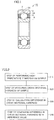
- a bearing 10 includes an annular outer race 2, an annular inner race 1 arranged inside outer race 2, and a plurality of balls 3 as rolling elements arranged between outer race 2 and inner race 1 and held in an annular holder 4, inner race 1, outer race 2, and balls 3 being made of JIS standard JUS2.
- An outer raceway surface 2A is formed in an inner peripheral surface of outer race 2
- an inner raceway surface 1A is formed in an outer peripheral surface of inner race 1.
- Outer race 2 and inner race 1 are arranged such that inner raceway surface 1A and outer raceway surface 2A face each other.
- the plurality of balls 3 come into contact with inner raceway surface 1A and outer raceway surface 2A at ball rolling surfaces 3A as their surfaces, are circumferentially arranged at a predetermined pitch by holder 4, and thereby held on an annular raceway in a freely rolling manner.
- outer race 2 and inner race 1 of bearing 10 are relatively rotatable with respect to each other.
- At least outer raceway surface 2A of outer race 2 is a region where a carbonitrided layer is formed.
- Inner raceway surface 1A of inner race 1 is also a region where a carbonitrided layer is formed.
- a carbonitrided layer is formed in the surface of each ball 3.
- a nitrogen concentration in surfaces of the carbonitrided layers in inner race 1, outer race 2, and balls 3 is not less than 0.1 mass %.
- inner race 1, outer race 2, and balls 3 as bearing parts in accordance with the present disclosure described above are each a bearing part made of JIS standard SUJ2 and having a carbonitrided layer formed in a surface thereof, wherein, after heat treatment at a heating temperature of 500°C for a retention time of one hour (i.e., high-temperature tempering) is performed, a Vickers hardness at a position with a depth of 30 ⁇ m from the surface is higher than a Vickers hardness at a core portion, which is a region where the carbonitrided layer is not formed in a thickness direction of the bearing part (inner race 1, outer race 2, ball 3), by not less than 130 HV.
- Such a configuration can assure that the nitrogen concentration in the surface in the bearing part is not less than 0.1 mass % as described later, and can extend the life of a bearing using the bearing part as a result.
- a Vickers hardness at a position with a depth of 70 ⁇ m from the surface is higher than the Vickers hardness at the core portion by not less than 80 HV.
- Such a configuration can reliably assure that the nitrogen concentration in the surface of the carbonitrided layer before the heat treatment is not less than 0.1 mass %.
- a difference between the Vickers hardnesses at a region within the carbonitrided layer and at the core portion, and the nitrogen concentration have a linear relationship when the nitrogen concentration is in a range of about 0 to 0.1 mass %. Therefore, if the nitrogen concentration used for determination is set to a value close to substantially the center of the range exhibiting the linear relationship (for example, 0.06 mass %), a relatively good correlation between the difference in the Vickers hardness and the nitrogen concentration is obtained, and thus correctness of the determination can be improved.
- the bearing part (inner race 1, outer race 2, ball 3) in accordance with the present disclosure is a bearing part made of JIS standard SUJ2 and having a carbonitrided layer formed in a surface thereof, wherein, after heat treatment at a heating temperature of 500°C for a retention time of one hour is performed, a Vickers hardness at a position with a depth of 70 ⁇ m from the surface is higher than a Vickers hardness at a core portion, which is a region where the carbonitrided layer is not formed in a thickness direction of the bearing part, by not less than 80 HV.
- Such a configuration can reliably assure that the nitrogen concentration in the surface of the carbonitrided layer before the heat treatment is not less than 0.1 mass %, as described later.
- the nitrogen concentration in the surface of the carbonitrided layer, for example in the rolling surface is not less than 0.1 mass %. In this case, the life of the bearing part (inner race 1, outer race 2, ball 3) can be reliably extended.
- the carbonitrided layer may be formed by carbonitriding treatment performed at a treatment temperature in a temperature range of not less than a point A 1 and not more than a point A cm . In this case, the carbonitrided layer can be reliably formed in the bearing part such as inner race 1, outer race 2, and ball 3.
- the carbonitrided layer may be formed by carbonitriding treatment performed at a treatment temperature in a temperature range of, for example, not less than 840°C and not more than 860°C. In this case, the carbonitrided layer can be reliably formed in the bearing part such as inner race 1, outer race 2, and ball 3.
- Bearing 10 in accordance with the present disclosure is a bearing manufactured using the bearing part such as inner race 1, outer race 2, and ball 3. With such a configuration, a bearing with a reliably extended life when compared with a bearing using a non-nitrided bearing part can be obtained by quantitatively assuring the nitrogen concentration in the surface of the carbonitrided layer.
- the nitrogen concentration in the surface of the bearing part such as inner race 1, outer race 2, and ball 3 constituting bearing 10 shown in Fig. 1 can be inspected by an inspection method as described below.
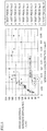
- a method for inspecting the bearing part in accordance with the present invention will be described with reference to Fig. 2 .
- a sample as the bearing part such as inner race 1, outer race 2, and ball 3 subjected to carbonitriding treatment and the like is prepared to perform the step of performing high-temperature tempering on the sample (S10).
- a tempering temperature heating retention temperature
- a tempering time retention time
- the carbonitrided layer has a Vickers hardness higher than a Vickers hardness in a region other than the carbonitrided layer.
- a cross sectional hardness of the sample is performed as shown in Fig. 2 .
- inner race 1 see Fig. 1
- a test piece is cut out of the sample, and a cross sectional hardness (Vickers hardness) of the test piece is measured at a predetermined position in the thickness direction from an outer diameter side toward an inner diameter side.
- the hardness may be measured, for example, at two positions 30 ⁇ m and 1 mm from a surface (surface on the outer diameter side), or two positions 70 ⁇ m and 1 mm from the surface, or three positions 30 ⁇ m, 70 ⁇ m, and 1 mm from the surface.
- the step of calculating a difference in cross sectional hardness (S30) is performed as shown in Fig. 2 . Specifically, a difference between the Vickers hardness at the position 1 mm from the surface corresponding to the core portion as the region other than the carbonitrided layer and the Vickers hardness at the position 30 ⁇ m or 70 ⁇ m from the surface is calculated.
- the step of comparing the difference in cross sectional hardness with a reference value is performed. Specifically, the difference in cross sectional hardness calculated in the above step (S30) is compared with a predetermined reference value to determine whether or not the value of the difference satisfies the reference value (i.e., whether or not the value of the difference is not less than the reference value). If the value of the difference satisfies the reference value, it can be confirmed that the nitrogen concentration in the surface before the heat treatment (high-temperature tempering) is performed on the sample is a predetermined value (for example, 0.1 mass %).
- a predetermined value for example, 0.1 mass %
- the inspection method includes the steps of: preparing a bearing part (for example, inner race 1, outer race 2, ball 3) made of JIS standard SUJ2 and having a carbonitrided layer formed in a surface thereof; performing heat treatment on the bearing part (S10); measuring, after the heat treatment, a first Vickers hardness at a position with a summed depth from the surface, the summed depth being obtained by adding a first distance to a grinding allowance for the surface, and a second Vickers hardness at a core portion, which is a region where the carbonitrided layer is not formed in a thickness direction of the bearing part (S20); and determining whether or not the first Vickers hardness is higher than the second Vickers hardness by a reference value (S30, S40).
- the nitrogen concentration in the surface of the bearing part such as inner race 1, outer race 2, and ball 3 can be quantitatively assured based on the inventor's new findings that, in the bearing part such as inner race 1 made of JIS standard SUJ2, there is a correlation between the Vickers hardness and the nitrogen concentration in the carbonitrided layer subjected to heat treatment under predetermined conditions, and that nitrogen distribution is shifted toward an inner side in the thickness direction by a predetermined distance due to the heat treatment, as described later.
- the heat treatment is heat treatment at a heating temperature of 500°C for a retention time of one hour
- the first distance may be 30 ⁇ m
- the reference value may be 130 HV.
- whether or not the nitrogen concentration in the surface of the bearing part before the heat treatment is not less than 0.1 mass % can be determined based on the inventor's findings that there is a correlation between the Vickers hardness and the nitrogen concentration after heat treatment (high-temperature tempering) as described above is performed, and that the nitrogen distribution is shifted toward the inner side in the thickness direction by about 30 ⁇ m due to the heat treatment.
- the heat treatment is heat treatment at a heating temperature of 500°C for a retention time of one hour
- the first distance may be 70 ⁇ m
- the reference value may be 80 HV.
- whether or not the nitrogen concentration in the surface of the bearing part before the heat treatment is not less than 0.1 mass % can be determined with higher accuracy.
- the nitrogen concentration confirmed in the surface of the carbonitrided layer in the bearing part is not less than 0.1 mass %.
- the bearing part determined by the inspection method as passing the inspection can reliably achieve the effect of extending the life.
- the carbonitrided layer may be formed by carbonitriding treatment performed at a treatment temperature in a temperature range of not less than a point A 1 and not more than a point A cm . Further, in the inspection method described above, the carbonitrided layer may be formed by carbonitriding treatment performed at a treatment temperature in a temperature range of not less than 840°C and not more than 860°C.
- the heating retention temperature suitable for an inspection was determined as described below, by setting the retention time to a fixed time (one hour) and changing the heating retention temperature to 300°C, 400°C, 500°C, 600°C, and 700°C to investigate a heating retention temperature at which a difference in hardness was clearest.
- a difference in hardenability and a difference in cooling rate during hardening due to a difference in chemical components in each material may affect a hardness after the hardening and also may affect a hardness after the high-temperature tempering.
- the absolute value itself of a cross sectional hardness is not used as an indicator for the inspection, but a hardness difference between a hardness at a non-nitrided position deep from a surface layer (core portion) (here, for example, a hardness at a depth of 1 mm from an uppermost surface subjected to heat treatment) and a hardness at a position with a certain depth within a nitrided region was adopted as an indicator for the present inspection method.
- Table 1 shows chemical components of test pieces subjected to an investigation.
- the materials were all made of JIS standard SUJ2, and subjected to carbonitriding treatment in various heat treatment furnaces and under various heat treatment atmospheres. It is noted that the carbonitriding treatment temperature was included in a temperature range of not less than 840°C and not more than 860°C. [Table 1] Test Piece No.
- test piece No.1 was subjected to treatment under conditions of a carbonitriding treatment temperature of 850°C, a treatment time of 120 minutes (min.) (hereinafter expressed as "850°C ⁇ 120 min.”), an undecomposed NH 3 fraction of 0.2 vol. %, and a carbon activity of 0.9.
- Test piece No. 2 was subjected to treatment under conditions of 840°Cx70 min., an undecomposed ammonia fraction of 0.1 vol. %, and a carbon activity of 0.85.
- Test piece No. 3 was subjected to treatment under conditions of 850°C ⁇ 120 min., an undecomposed ammonia fraction of 0.1 vol. %, and a carbon activity of 0.9.
- Test piece No. 5 was subjected to treatment under conditions of 850°C ⁇ 90 min., an undecomposed ammonia fraction of 0.1 vol. %, and a carbon activity of 0.9.
- test piece No. 6 was subjected to treatment under conditions of 850°C ⁇ 90 min., an undecomposed ammonia fraction of 0.13 vol. %, and a carbon activity of 0.9.
- Test piece No. 7 was subjected to treatment under conditions of 850°C ⁇ 150 min., an undecomposed ammonia fraction of 0.1 vol. %, and a carbon activity of 0.85.
- Test piece No. 8 was subjected to treatment under conditions of 850°C ⁇ 150 min., an undecomposed ammonia fraction of 0.25 vol. %, and a carbon activity of 0.9.
- Test piece No. 9 was subjected to treatment under conditions of 850°C ⁇ 180 min., an undecomposed ammonia fraction of 0.3 vol. %, and a carbon activity of 0.95.
- Test piece No. 10 was subjected to treatment under conditions of 850°C ⁇ 90 min., an undecomposed ammonia fraction of 0.2 vol. %, and a carbon activity of 0.9.
- Fig. 3 shows a schematic view of a sample used for EPMA analysis and a measurement method.
- inner race 1 (see Fig. 1 ) is used as a sample 11 as shown in Fig. 3 .
- sample 11 a nitrogen concentration in sample 11 subjected to the carbonitriding treatment was measured.
- a test piece 12 as shown in Fig. 3 was cut out of sample 11, and line analysis with an EPMA was performed on a cut-out end surface at a central portion in a height direction of test piece 12 (i.e., at a position with a half width) along a direction from a surface 13 on an outer diameter side to a surface 14 on an inner diameter side of the test piece.
- Hardness was measured at the cut-out end surface subjected to the EPMA analysis in the test piece described above in (1-3). As a measuring method, Vickers hardness measurement was performed using a micro Vickers hardness tester.
- the test pieces subjected to the carbonitriding treatment were subjected to tempering at a heating temperature of 180°C for a retention time of two hours, and thereafter subjected to five types of high-temperature tempering at heating retention temperatures of 300°C, 400°C, 500°C, 600°C, and 700°C for a retention time of one hour.
- the high-temperature tempering was performed in an air atmosphere.
- cross sectional hardnesses of the test pieces treated under the respective conditions for the high-temperature tempering were measured.
- measurement was performed on test pieces No. 8 and No. 9 which were under carbonitriding treatment conditions considered to cause a large amount of nitrogen to enter the test pieces.
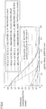
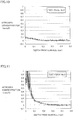
- Fig. 4 shows a graph compiling experimental results.
- the graph shown in Fig. 4 compiles the experimental results, with the tempering temperature on the axis of abscissas and the difference in cross sectional hardness (i.e., [the maximum value of the cross sectional hardness] - [the cross sectional hardness at a position with the depth of 1 mm from the uppermost surface subjected to the heat treatment]: also expressed as ⁇ HV) on the axis of ordinates.
- difference ⁇ HV in cross sectional hardness was maximum after the high-temperature tempering at the heating retention temperature of 500°C for the retention time of one hour.
- Difference ⁇ HV in cross sectional hardness at the heating retention temperature of 500°C had a value about double that of difference ⁇ HV in cross sectional hardness after the high-temperature tempering at the heating retention temperature of 300°C or 700°C. Accordingly, it is considered that the hardness after the tempering having a relatively high correlation with the nitrogen concentration is the hardness after the tempering at a heating retention temperature of about 500°C. Therefore, in an experiment below, measurement of the cross sectional hardness was performed on the test pieces subjected to high-temperature tempering at a heating retention temperature of 500°C for a retention time of one hour.
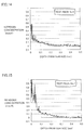
- each test piece having a composition shown in Table 1 was subjected to the heat treatment at the heating retention temperature of 500°C for the retention time of one hour as the high-temperature tempering, and thereafter a nitrogen concentration in each test piece was measured by the EPMA analysis as described with reference to Fig. 3 . Further, a cross sectional hardness in a depth direction of the test piece was measured in the cut-out end surface of test piece 12 shown in Fig. 3 . Then, relationship of a difference between a cross sectional hardness at a certain position in the depth direction and the cross sectional hardness at the position with the depth of 1 mm from the uppermost surface subjected to the heat treatment (hereinafter defined as a cross sectional hardness difference ( ⁇ HV)) was investigated.
- ⁇ HV cross sectional hardness difference
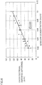
- Fig. 5 shows results thereof.
- the axis of abscissas represents the nitrogen concentration (unit: mass %)
- the axis of ordinates represents the cross sectional hardness difference ( ⁇ HV) (unit: Vickers hardness).
- the axis of abscissas represents the nitrogen concentration (unit: mass %), and the axis of ordinates represents cross sectional hardness difference ⁇ HV (unit: Vickers hardness).
- ⁇ HV unit: Vickers hardness
- Fig. 7 is a graph with cross sectional hardness difference ⁇ HV (unit: Vickers hardness) on the axis of abscissas and the nitrogen concentration (unit: mass %) on the axis of ordinates, plotting the data shown in Fig. 6 . From these data, an approximate equation expressing the relationship between the nitrogen concentration and the cross sectional hardness difference is determined. Fig. 7 also shows the approximate equation. As shown in Fig.
- an inspection method for assuring that the nitrogen concentration in a ground uppermost surface (i.e., a final uppermost surface of the bearing part) is a predetermined value (for example, specifically, not less than 0.1 mass %) is proposed, and a component (bearing part) of a rolling bearing for which the nitrogen concentration is assured is provided based on the inspection method.
- the maximum distance between the depth position having the nitrogen concentration of 0.1 mass % and the depth position having the nitrogen concentration of 0.06 mass % is 40 ⁇ m. Accordingly, it is considered based on Fig. 8 and the like that the nitrogen concentration is not less than 0.1 mass % in a range from a position which is 40 ⁇ m closer to a surface side of the carbonitriding-treated part than the depth position having the nitrogen concentration of 0.06 mass %, to the surface.
- the cross sectional hardness difference ( ⁇ HV) at a certain depth position is not less than 80, it can be assured that the nitrogen concentration in a region 40 ⁇ m closer to the surface from the depth position is not less than 0.1 mass %. It is noted that the nitrogen concentration in a region 40 ⁇ m shifted to the surface side from the depth position having the nitrogen concentration of 0.06 mass % in each of four conditions shown in Fig. 8 is calculated to have a value shown in Table 2.
- Table 2 shows a nitridation time (carbonitriding treatment time), an undecomposed NH 3 volume fraction, and a nitrogen concentration in the ground uppermost surface corresponding to the nitrogen concentration in the region 40 ⁇ m shifted to the surface side from the depth position having the nitrogen concentration of 0.06 mass %, in each condition.
- the nitrogen concentration in the region is not less than 0.1 mass %.
- the inspection method (quality assurance method) to be proposed by the inventor of the present invention is to indicate that the nitrogen concentration before the high-temperature tempering at the heating retention temperature of 500°C for the retention time of one hour is performed, that is, the nitrogen concentration in a ground uppermost surface of an actual product, is not less than 0.1 mass %.
- nitride concentration distribution was measured for each of test pieces No. 3, No. 8, No. 9, and No.
- Table 3 shows, from the left, the test piece No., the nitrogen concentration (unit: mass %) in the region where the depth from the specimen surface was measured, the depth from the test piece surface to the region (unit: ⁇ m) before the high-temperature tempering was performed, the depth from the test piece surface to the region (unit: ⁇ m) after the high-temperature tempering was performed, the moving distance (unit: ⁇ m) of the region in the depth direction by the high-temperature tempering, and the average value (unit: ⁇ m) of the moving distances of the region for each nitrogen concentration.
- the nitrogen concentration is not less than 0.1 mass % from a region which is 40 ⁇ m closer to the surface side (i.e., shallower) than a region having a nitrogen concentration of 0.06 mass %, to the surface, it is necessary to consider the nitrogen moving distance described above due to the high-temperature tempering (tempering of 500°C ⁇ 1h) in order to assure that the nitrogen concentration in the ground uppermost surface before the high-temperature tempering (tempering of 500°C ⁇ 1h) is not less than 0.1 mass %.
- the maximum distance between the depth having the nitrogen concentration of 0.1 mass % and the depth having the nitrogen concentration of 0.06 mass % is 40 ⁇ m, and the nitrogen moving distance due to the high-temperature tempering (tempering of 500°C ⁇ 1h) is 30 ⁇ m, a summed distance (70 ⁇ m) of the maximum distance (40 ⁇ m) and the nitrogen moving distance (30 ⁇ m) should be considered.
- the nitrogen concentration at a position with a depth obtained by adding a grinding allowance (only for one surface) for the carbonitriding-treated bearing part to the summed distance is not less than 0.06 mass % (that is, if the cross sectional hardness difference after the high-temperature tempering (tempering of 500°C ⁇ 1h) is not less than 80), it can be assured that the nitrogen concentration in the ground uppermost surface before the high-temperature tempering (tempering of 500°C ⁇ 1h) is not less than 0.1 mass %.
- the present inspection method was applied to test pieces to determine whether each test piece passed or failed the inspection, and compare their actual measurement values of the nitrogen concentration.
- the test pieces shown in Table 1 were used as the test pieces.
- Table 4 shows, from the left column, the test piece No., the grinding allowance for one surface of each test piece (unit: ⁇ m), the cross sectional hardness difference ( ⁇ HV) as the difference between the cross sectional hardness at the position with the depth of [the grinding allowance + 70 ⁇ m] from the surface and the cross sectional hardness at the position 1 mm from the surface after the high-temperature tempering (tempering of 500°C ⁇ 1h), the result of pass/fail determination based on the present inspection method, and the actual measurement value of the nitrogen concentration (unit: mass %) at a position of the ground uppermost surface measured with an EPMA before the high-temperature tempering was performed.
- the present inspection method quality assurance method
- the present inspection method can be considered as a method appropriate for determining that the nitrogen concentration at the position of the ground uppermost surface is not less than 0.1 mass %.
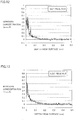
- Figs. 9 to 18 each show an actual measurement value of nitrogen concentration distribution in each test piece before the high-temperature tempering (tempering of 500°C ⁇ 1h).
- the axis of abscissas represents the depth from the surface (unit: mm), and the axis of ordinates represents the nitrogen concentration (unit: mass %).
- the present invention is particularly advantageously applicable to carbonitriding-treated bearing part and bearing.
Landscapes
- Chemical & Material Sciences (AREA)
- Engineering & Computer Science (AREA)
- Mechanical Engineering (AREA)
- Materials Engineering (AREA)
- Metallurgy (AREA)
- Organic Chemistry (AREA)
- General Engineering & Computer Science (AREA)
- Chemical Kinetics & Catalysis (AREA)
- Thermal Sciences (AREA)
- Crystallography & Structural Chemistry (AREA)
- Physics & Mathematics (AREA)
- Manufacturing & Machinery (AREA)
- Rolling Contact Bearings (AREA)
- Solid-Phase Diffusion Into Metallic Material Surfaces (AREA)
- Heat Treatment Of Articles (AREA)
- Testing Of Devices, Machine Parts, Or Other Structures Thereof (AREA)
Applications Claiming Priority (2)
| Application Number | Priority Date | Filing Date | Title |
|---|---|---|---|
| JP2010075370A JP5679543B2 (ja) | 2010-03-29 | 2010-03-29 | 軸受部品および軸受 |
| PCT/JP2011/057849 WO2011122632A1 (ja) | 2010-03-29 | 2011-03-29 | 軸受部品、軸受および軸受部品の検査方法 |
Publications (3)
| Publication Number | Publication Date |
|---|---|
| EP2554709A1 EP2554709A1 (en) | 2013-02-06 |
| EP2554709A4 EP2554709A4 (en) | 2014-05-28 |
| EP2554709B1 true EP2554709B1 (en) | 2020-10-07 |
Family
ID=44712327
Family Applications (1)
| Application Number | Title | Priority Date | Filing Date |
|---|---|---|---|
| EP11762856.0A Active EP2554709B1 (en) | 2010-03-29 | 2011-03-29 | Bearing part inspection method |
Country Status (5)
| Country | Link |
|---|---|
| US (1) | US9032783B2 (enExample) |
| EP (1) | EP2554709B1 (enExample) |
| JP (1) | JP5679543B2 (enExample) |
| CN (1) | CN102859025A (enExample) |
| WO (1) | WO2011122632A1 (enExample) |
Families Citing this family (10)
| Publication number | Priority date | Publication date | Assignee | Title |
|---|---|---|---|---|
| DE102012212426B3 (de) * | 2012-07-16 | 2013-08-29 | Schaeffler Technologies AG & Co. KG | Wälzlagerelement, insbesondere Wälzlagerring |
| US10053764B2 (en) * | 2012-08-21 | 2018-08-21 | Aktiebolaget Skf | Method and steel component |
| JP6241638B2 (ja) * | 2012-08-22 | 2017-12-06 | 三菱日立パワーシステムズ株式会社 | 時効条件設定方法及びタービン翼の製造方法 |
| KR102053485B1 (ko) * | 2012-10-17 | 2019-12-06 | 에누티에누 가부시기가이샤 | 베어링 부품, 구름베어링 및 베어링 부품의 제조 방법 |
| JP6026915B2 (ja) | 2013-02-13 | 2016-11-16 | Ntn株式会社 | 軸受部品および転がり軸受の検査方法 |
| WO2014196431A1 (ja) * | 2013-06-06 | 2014-12-11 | Ntn株式会社 | 軸受部品および転がり軸受 |
| US10094422B2 (en) | 2013-06-06 | 2018-10-09 | Ntn Corporation | Bearing component and rolling bearing |
| US10156259B2 (en) | 2013-06-06 | 2018-12-18 | Ntn Corporation | Bearing component and rolling bearing |
| WO2014196430A1 (ja) | 2013-06-06 | 2014-12-11 | Ntn株式会社 | 軸受部品および転がり軸受 |
| CN104328373A (zh) * | 2014-10-22 | 2015-02-04 | 人本集团有限公司 | 一种高碳铬轴承钢碳氮共渗有效硬化层深度检测方法 |
Family Cites Families (11)
| Publication number | Priority date | Publication date | Assignee | Title |
|---|---|---|---|---|
| JP2962817B2 (ja) | 1990-11-28 | 1999-10-12 | 日本精工株式会社 | 転がり軸受 |
| JP3047088B2 (ja) * | 1992-02-28 | 2000-05-29 | エヌティエヌ株式会社 | 転動体を有する機械部品 |
| WO1995007417A1 (en) | 1993-09-08 | 1995-03-16 | Ntn Corporation | Mechanical part having rolling elements |
| TW408212B (en) * | 1996-10-11 | 2000-10-11 | Sanyo Electric Co | Method for treating metal surface, rotary shaft and vane for refrigerant compressor treated by the method, and refrigerant compressor using the same |
| JP3702618B2 (ja) | 1997-11-04 | 2005-10-05 | 日本精工株式会社 | トロイダル形無段変速機 |
| JPH11304795A (ja) * | 1998-04-21 | 1999-11-05 | Nippon Seiko Kk | 鋼部品の窒素侵入深さ検出方法 |
| JP2001280348A (ja) * | 2000-03-28 | 2001-10-10 | Nsk Ltd | 転がり軸受 |
| JP4423754B2 (ja) * | 2000-06-22 | 2010-03-03 | 日本精工株式会社 | 転動軸の製造方法 |
| EP1245699B1 (en) * | 2001-03-30 | 2011-05-11 | Hitachi Metals, Ltd. | Coated tool for warm and/or hot working |
| WO2007135929A1 (ja) * | 2006-05-19 | 2007-11-29 | Nsk Ltd. | 転がり軸受 |
| JP2009229288A (ja) * | 2008-03-24 | 2009-10-08 | Ntn Corp | 転動疲労寿命の試験方法 |
-
2010
- 2010-03-29 JP JP2010075370A patent/JP5679543B2/ja active Active
-
2011
- 2011-03-29 WO PCT/JP2011/057849 patent/WO2011122632A1/ja not_active Ceased
- 2011-03-29 EP EP11762856.0A patent/EP2554709B1/en active Active
- 2011-03-29 CN CN2011800173096A patent/CN102859025A/zh active Pending
- 2011-03-29 US US13/637,954 patent/US9032783B2/en active Active
Non-Patent Citations (1)
| Title |
|---|
| CHIKARA OHKI: "Estimation of Nitrogen Concentration Distribution for Carbonitrided SUJ2 Steel", TETSU TO HAGANE: JOURNAL OF THE IRON AND STEEL INSTITUTE OF JAPAN, vol. 93, no. 3, 1 January 2007 (2007-01-01), JP, pages 220 - 227, XP055252322, ISSN: 0021-1575, DOI: 10.2355/tetsutohagane.93.220 * |
Also Published As
| Publication number | Publication date |
|---|---|
| JP2011209021A (ja) | 2011-10-20 |
| EP2554709A4 (en) | 2014-05-28 |
| US9032783B2 (en) | 2015-05-19 |
| CN102859025A (zh) | 2013-01-02 |
| JP5679543B2 (ja) | 2015-03-04 |
| EP2554709A1 (en) | 2013-02-06 |
| US20130019666A1 (en) | 2013-01-24 |
| WO2011122632A1 (ja) | 2011-10-06 |
Similar Documents
| Publication | Publication Date | Title |
|---|---|---|
| EP2554709B1 (en) | Bearing part inspection method | |
| EP2910657B1 (en) | Bearing element, rolling bearing and process for producing bearing element | |
| EP2716784A1 (en) | Rolling sliding member, method of manufacturing the same, and rolling bearing | |
| EP3006754B1 (en) | Bearing component and rolling bearing | |
| US10344801B2 (en) | Bearing part and rolling bearing | |
| JPS62218542A (ja) | 軸受軌道輪 | |
| JP2007100126A (ja) | 転動部材および転がり軸受 | |
| JP2016148393A (ja) | 転がり軸受ならびに転がり軸受の耐圧痕性および音響劣化度の評価方法 | |
| WO2018155588A1 (ja) | 軸受部品の製造方法 | |
| EP3006577B1 (en) | Bearing component and rolling bearing | |
| EP3564398B1 (en) | Method for manufacturing a bearing component. | |
| JPH11304795A (ja) | 鋼部品の窒素侵入深さ検出方法 | |
| Mason et al. | Optimizing Carburization in 8620H Steel Components | |
| JP6211812B2 (ja) | 軸受部品および転がり軸受 | |
| Ivanov | One Approach to Eddy Current Testing of Carburized Parts | |
| EP3006755A1 (en) | Bearing component and rolling bearing | |
| JP2005114149A (ja) | 転がり軸受 | |
| JP2005114145A (ja) | 転がり軸受 |
Legal Events
| Date | Code | Title | Description |
|---|---|---|---|
| PUAI | Public reference made under article 153(3) epc to a published international application that has entered the european phase |
Free format text: ORIGINAL CODE: 0009012 |
|
| 17P | Request for examination filed |
Effective date: 20121004 |
|
| AK | Designated contracting states |
Kind code of ref document: A1 Designated state(s): AL AT BE BG CH CY CZ DE DK EE ES FI FR GB GR HR HU IE IS IT LI LT LU LV MC MK MT NL NO PL PT RO RS SE SI SK SM TR |
|
| DAX | Request for extension of the european patent (deleted) | ||
| A4 | Supplementary search report drawn up and despatched |
Effective date: 20140430 |
|
| RIC1 | Information provided on ipc code assigned before grant |
Ipc: F16C 33/32 20060101ALI20140424BHEP Ipc: C23C 8/32 20060101AFI20140424BHEP Ipc: C21D 9/40 20060101ALI20140424BHEP Ipc: C23C 8/76 20060101ALI20140424BHEP Ipc: F16C 19/02 20060101ALI20140424BHEP Ipc: F16C 33/62 20060101ALI20140424BHEP Ipc: C21D 1/06 20060101ALI20140424BHEP Ipc: C23C 8/56 20060101ALI20140424BHEP Ipc: C23C 8/80 20060101ALI20140424BHEP Ipc: F16C 33/64 20060101ALI20140424BHEP |
|
| 17Q | First examination report despatched |
Effective date: 20160315 |
|
| STAA | Information on the status of an ep patent application or granted ep patent |
Free format text: STATUS: EXAMINATION IS IN PROGRESS |
|
| REG | Reference to a national code |
Ref country code: DE Ref legal event code: R079 Ref document number: 602011068847 Country of ref document: DE Free format text: PREVIOUS MAIN CLASS: C23C0008320000 Ipc: C21D0001060000 |
|
| GRAP | Despatch of communication of intention to grant a patent |
Free format text: ORIGINAL CODE: EPIDOSNIGR1 |
|
| STAA | Information on the status of an ep patent application or granted ep patent |
Free format text: STATUS: GRANT OF PATENT IS INTENDED |
|
| RIC1 | Information provided on ipc code assigned before grant |
Ipc: C23C 8/76 20060101ALI20200506BHEP Ipc: F16C 33/62 20060101ALI20200506BHEP Ipc: C23C 8/80 20060101ALI20200506BHEP Ipc: F16C 33/32 20060101ALI20200506BHEP Ipc: C23C 8/32 20060101ALI20200506BHEP Ipc: C21D 9/40 20060101ALI20200506BHEP Ipc: C21D 1/06 20060101AFI20200506BHEP Ipc: C23C 8/56 20060101ALI20200506BHEP Ipc: F16C 33/64 20060101ALI20200506BHEP |
|
| INTG | Intention to grant announced |
Effective date: 20200525 |
|
| GRAS | Grant fee paid |
Free format text: ORIGINAL CODE: EPIDOSNIGR3 |
|
| GRAA | (expected) grant |
Free format text: ORIGINAL CODE: 0009210 |
|
| STAA | Information on the status of an ep patent application or granted ep patent |
Free format text: STATUS: THE PATENT HAS BEEN GRANTED |
|
| AK | Designated contracting states |
Kind code of ref document: B1 Designated state(s): AL AT BE BG CH CY CZ DE DK EE ES FI FR GB GR HR HU IE IS IT LI LT LU LV MC MK MT NL NO PL PT RO RS SE SI SK SM TR |
|
| REG | Reference to a national code |
Ref country code: GB Ref legal event code: FG4D |
|
| REG | Reference to a national code |
Ref country code: CH Ref legal event code: EP Ref country code: AT Ref legal event code: REF Ref document number: 1321225 Country of ref document: AT Kind code of ref document: T Effective date: 20201015 |
|
| REG | Reference to a national code |
Ref country code: DE Ref legal event code: R096 Ref document number: 602011068847 Country of ref document: DE |
|
| REG | Reference to a national code |
Ref country code: IE Ref legal event code: FG4D |
|
| REG | Reference to a national code |
Ref country code: NL Ref legal event code: MP Effective date: 20201007 |
|
| REG | Reference to a national code |
Ref country code: AT Ref legal event code: MK05 Ref document number: 1321225 Country of ref document: AT Kind code of ref document: T Effective date: 20201007 |
|
| PG25 | Lapsed in a contracting state [announced via postgrant information from national office to epo] |
Ref country code: GR Free format text: LAPSE BECAUSE OF FAILURE TO SUBMIT A TRANSLATION OF THE DESCRIPTION OR TO PAY THE FEE WITHIN THE PRESCRIBED TIME-LIMIT Effective date: 20210108 Ref country code: FI Free format text: LAPSE BECAUSE OF FAILURE TO SUBMIT A TRANSLATION OF THE DESCRIPTION OR TO PAY THE FEE WITHIN THE PRESCRIBED TIME-LIMIT Effective date: 20201007 Ref country code: RS Free format text: LAPSE BECAUSE OF FAILURE TO SUBMIT A TRANSLATION OF THE DESCRIPTION OR TO PAY THE FEE WITHIN THE PRESCRIBED TIME-LIMIT Effective date: 20201007 Ref country code: NL Free format text: LAPSE BECAUSE OF FAILURE TO SUBMIT A TRANSLATION OF THE DESCRIPTION OR TO PAY THE FEE WITHIN THE PRESCRIBED TIME-LIMIT Effective date: 20201007 Ref country code: NO Free format text: LAPSE BECAUSE OF FAILURE TO SUBMIT A TRANSLATION OF THE DESCRIPTION OR TO PAY THE FEE WITHIN THE PRESCRIBED TIME-LIMIT Effective date: 20210107 Ref country code: PT Free format text: LAPSE BECAUSE OF FAILURE TO SUBMIT A TRANSLATION OF THE DESCRIPTION OR TO PAY THE FEE WITHIN THE PRESCRIBED TIME-LIMIT Effective date: 20210208 |
|
| REG | Reference to a national code |
Ref country code: LT Ref legal event code: MG4D |
|
| PG25 | Lapsed in a contracting state [announced via postgrant information from national office to epo] |
Ref country code: IS Free format text: LAPSE BECAUSE OF FAILURE TO SUBMIT A TRANSLATION OF THE DESCRIPTION OR TO PAY THE FEE WITHIN THE PRESCRIBED TIME-LIMIT Effective date: 20210207 Ref country code: ES Free format text: LAPSE BECAUSE OF FAILURE TO SUBMIT A TRANSLATION OF THE DESCRIPTION OR TO PAY THE FEE WITHIN THE PRESCRIBED TIME-LIMIT Effective date: 20201007 Ref country code: AT Free format text: LAPSE BECAUSE OF FAILURE TO SUBMIT A TRANSLATION OF THE DESCRIPTION OR TO PAY THE FEE WITHIN THE PRESCRIBED TIME-LIMIT Effective date: 20201007 Ref country code: BG Free format text: LAPSE BECAUSE OF FAILURE TO SUBMIT A TRANSLATION OF THE DESCRIPTION OR TO PAY THE FEE WITHIN THE PRESCRIBED TIME-LIMIT Effective date: 20210107 Ref country code: SE Free format text: LAPSE BECAUSE OF FAILURE TO SUBMIT A TRANSLATION OF THE DESCRIPTION OR TO PAY THE FEE WITHIN THE PRESCRIBED TIME-LIMIT Effective date: 20201007 Ref country code: PL Free format text: LAPSE BECAUSE OF FAILURE TO SUBMIT A TRANSLATION OF THE DESCRIPTION OR TO PAY THE FEE WITHIN THE PRESCRIBED TIME-LIMIT Effective date: 20201007 Ref country code: LV Free format text: LAPSE BECAUSE OF FAILURE TO SUBMIT A TRANSLATION OF THE DESCRIPTION OR TO PAY THE FEE WITHIN THE PRESCRIBED TIME-LIMIT Effective date: 20201007 |
|
| PG25 | Lapsed in a contracting state [announced via postgrant information from national office to epo] |
Ref country code: HR Free format text: LAPSE BECAUSE OF FAILURE TO SUBMIT A TRANSLATION OF THE DESCRIPTION OR TO PAY THE FEE WITHIN THE PRESCRIBED TIME-LIMIT Effective date: 20201007 |
|
| REG | Reference to a national code |
Ref country code: DE Ref legal event code: R097 Ref document number: 602011068847 Country of ref document: DE |
|
| PG25 | Lapsed in a contracting state [announced via postgrant information from national office to epo] |
Ref country code: CZ Free format text: LAPSE BECAUSE OF FAILURE TO SUBMIT A TRANSLATION OF THE DESCRIPTION OR TO PAY THE FEE WITHIN THE PRESCRIBED TIME-LIMIT Effective date: 20201007 Ref country code: EE Free format text: LAPSE BECAUSE OF FAILURE TO SUBMIT A TRANSLATION OF THE DESCRIPTION OR TO PAY THE FEE WITHIN THE PRESCRIBED TIME-LIMIT Effective date: 20201007 Ref country code: SM Free format text: LAPSE BECAUSE OF FAILURE TO SUBMIT A TRANSLATION OF THE DESCRIPTION OR TO PAY THE FEE WITHIN THE PRESCRIBED TIME-LIMIT Effective date: 20201007 Ref country code: RO Free format text: LAPSE BECAUSE OF FAILURE TO SUBMIT A TRANSLATION OF THE DESCRIPTION OR TO PAY THE FEE WITHIN THE PRESCRIBED TIME-LIMIT Effective date: 20201007 Ref country code: SK Free format text: LAPSE BECAUSE OF FAILURE TO SUBMIT A TRANSLATION OF THE DESCRIPTION OR TO PAY THE FEE WITHIN THE PRESCRIBED TIME-LIMIT Effective date: 20201007 Ref country code: LT Free format text: LAPSE BECAUSE OF FAILURE TO SUBMIT A TRANSLATION OF THE DESCRIPTION OR TO PAY THE FEE WITHIN THE PRESCRIBED TIME-LIMIT Effective date: 20201007 |
|
| PLBE | No opposition filed within time limit |
Free format text: ORIGINAL CODE: 0009261 |
|
| STAA | Information on the status of an ep patent application or granted ep patent |
Free format text: STATUS: NO OPPOSITION FILED WITHIN TIME LIMIT |
|
| PG25 | Lapsed in a contracting state [announced via postgrant information from national office to epo] |
Ref country code: DK Free format text: LAPSE BECAUSE OF FAILURE TO SUBMIT A TRANSLATION OF THE DESCRIPTION OR TO PAY THE FEE WITHIN THE PRESCRIBED TIME-LIMIT Effective date: 20201007 |
|
| 26N | No opposition filed |
Effective date: 20210708 |
|
| REG | Reference to a national code |
Ref country code: DE Ref legal event code: R119 Ref document number: 602011068847 Country of ref document: DE |
|
| PG25 | Lapsed in a contracting state [announced via postgrant information from national office to epo] |
Ref country code: MC Free format text: LAPSE BECAUSE OF FAILURE TO SUBMIT A TRANSLATION OF THE DESCRIPTION OR TO PAY THE FEE WITHIN THE PRESCRIBED TIME-LIMIT Effective date: 20201007 Ref country code: IT Free format text: LAPSE BECAUSE OF FAILURE TO SUBMIT A TRANSLATION OF THE DESCRIPTION OR TO PAY THE FEE WITHIN THE PRESCRIBED TIME-LIMIT Effective date: 20201007 Ref country code: AL Free format text: LAPSE BECAUSE OF FAILURE TO SUBMIT A TRANSLATION OF THE DESCRIPTION OR TO PAY THE FEE WITHIN THE PRESCRIBED TIME-LIMIT Effective date: 20201007 |
|
| REG | Reference to a national code |
Ref country code: CH Ref legal event code: PL |
|
| GBPC | Gb: european patent ceased through non-payment of renewal fee |
Effective date: 20210329 |
|
| PG25 | Lapsed in a contracting state [announced via postgrant information from national office to epo] |
Ref country code: SI Free format text: LAPSE BECAUSE OF FAILURE TO SUBMIT A TRANSLATION OF THE DESCRIPTION OR TO PAY THE FEE WITHIN THE PRESCRIBED TIME-LIMIT Effective date: 20201007 |
|
| REG | Reference to a national code |
Ref country code: BE Ref legal event code: MM Effective date: 20210331 |
|
| PG25 | Lapsed in a contracting state [announced via postgrant information from national office to epo] |
Ref country code: DE Free format text: LAPSE BECAUSE OF NON-PAYMENT OF DUE FEES Effective date: 20211001 Ref country code: IE Free format text: LAPSE BECAUSE OF NON-PAYMENT OF DUE FEES Effective date: 20210329 Ref country code: GB Free format text: LAPSE BECAUSE OF NON-PAYMENT OF DUE FEES Effective date: 20210329 Ref country code: CH Free format text: LAPSE BECAUSE OF NON-PAYMENT OF DUE FEES Effective date: 20210331 Ref country code: LI Free format text: LAPSE BECAUSE OF NON-PAYMENT OF DUE FEES Effective date: 20210331 Ref country code: LU Free format text: LAPSE BECAUSE OF NON-PAYMENT OF DUE FEES Effective date: 20210329 |
|
| PG25 | Lapsed in a contracting state [announced via postgrant information from national office to epo] |
Ref country code: IS Free format text: LAPSE BECAUSE OF FAILURE TO SUBMIT A TRANSLATION OF THE DESCRIPTION OR TO PAY THE FEE WITHIN THE PRESCRIBED TIME-LIMIT Effective date: 20210207 |
|
| PG25 | Lapsed in a contracting state [announced via postgrant information from national office to epo] |
Ref country code: BE Free format text: LAPSE BECAUSE OF NON-PAYMENT OF DUE FEES Effective date: 20210331 |
|
| PG25 | Lapsed in a contracting state [announced via postgrant information from national office to epo] |
Ref country code: HU Free format text: LAPSE BECAUSE OF FAILURE TO SUBMIT A TRANSLATION OF THE DESCRIPTION OR TO PAY THE FEE WITHIN THE PRESCRIBED TIME-LIMIT; INVALID AB INITIO Effective date: 20110329 Ref country code: CY Free format text: LAPSE BECAUSE OF FAILURE TO SUBMIT A TRANSLATION OF THE DESCRIPTION OR TO PAY THE FEE WITHIN THE PRESCRIBED TIME-LIMIT Effective date: 20201007 |
|
| PG25 | Lapsed in a contracting state [announced via postgrant information from national office to epo] |
Ref country code: MK Free format text: LAPSE BECAUSE OF FAILURE TO SUBMIT A TRANSLATION OF THE DESCRIPTION OR TO PAY THE FEE WITHIN THE PRESCRIBED TIME-LIMIT Effective date: 20201007 |
|
| PG25 | Lapsed in a contracting state [announced via postgrant information from national office to epo] |
Ref country code: TR Free format text: LAPSE BECAUSE OF FAILURE TO SUBMIT A TRANSLATION OF THE DESCRIPTION OR TO PAY THE FEE WITHIN THE PRESCRIBED TIME-LIMIT Effective date: 20201007 |
|
| PG25 | Lapsed in a contracting state [announced via postgrant information from national office to epo] |
Ref country code: MT Free format text: LAPSE BECAUSE OF FAILURE TO SUBMIT A TRANSLATION OF THE DESCRIPTION OR TO PAY THE FEE WITHIN THE PRESCRIBED TIME-LIMIT Effective date: 20201007 |
|
| PGFP | Annual fee paid to national office [announced via postgrant information from national office to epo] |
Ref country code: FR Payment date: 20250210 Year of fee payment: 15 |