WO2011122483A1 - 防眩性フィルム、防眩性フィルムの製造方法、偏光板及び画像表示装置 - Google Patents
防眩性フィルム、防眩性フィルムの製造方法、偏光板及び画像表示装置 Download PDFInfo
- Publication number
- WO2011122483A1 WO2011122483A1 PCT/JP2011/057397 JP2011057397W WO2011122483A1 WO 2011122483 A1 WO2011122483 A1 WO 2011122483A1 JP 2011057397 W JP2011057397 W JP 2011057397W WO 2011122483 A1 WO2011122483 A1 WO 2011122483A1
- Authority
- WO
- WIPO (PCT)
- Prior art keywords
- fine particles
- diffusion layer
- organic fine
- film
- antiglare film
- Prior art date
- Legal status (The legal status is an assumption and is not a legal conclusion. Google has not performed a legal analysis and makes no representation as to the accuracy of the status listed.)
- Ceased
Links
Images
Classifications
-
- G—PHYSICS
- G02—OPTICS
- G02B—OPTICAL ELEMENTS, SYSTEMS OR APPARATUS
- G02B1/00—Optical elements characterised by the material of which they are made; Optical coatings for optical elements
- G02B1/10—Optical coatings produced by application to, or surface treatment of, optical elements
- G02B1/11—Anti-reflection coatings
- G02B1/111—Anti-reflection coatings using layers comprising organic materials
-
- G—PHYSICS
- G02—OPTICS
- G02B—OPTICAL ELEMENTS, SYSTEMS OR APPARATUS
- G02B1/00—Optical elements characterised by the material of which they are made; Optical coatings for optical elements
- G02B1/10—Optical coatings produced by application to, or surface treatment of, optical elements
-
- G—PHYSICS
- G02—OPTICS
- G02B—OPTICAL ELEMENTS, SYSTEMS OR APPARATUS
- G02B1/00—Optical elements characterised by the material of which they are made; Optical coatings for optical elements
- G02B1/10—Optical coatings produced by application to, or surface treatment of, optical elements
- G02B1/11—Anti-reflection coatings
- G02B1/118—Anti-reflection coatings having sub-optical wavelength surface structures designed to provide an enhanced transmittance, e.g. moth-eye structures
-
- G—PHYSICS
- G02—OPTICS
- G02B—OPTICAL ELEMENTS, SYSTEMS OR APPARATUS
- G02B5/00—Optical elements other than lenses
- G02B5/02—Diffusing elements; Afocal elements
- G02B5/0205—Diffusing elements; Afocal elements characterised by the diffusing properties
- G02B5/021—Diffusing elements; Afocal elements characterised by the diffusing properties the diffusion taking place at the element's surface, e.g. by means of surface roughening or microprismatic structures
- G02B5/0221—Diffusing elements; Afocal elements characterised by the diffusing properties the diffusion taking place at the element's surface, e.g. by means of surface roughening or microprismatic structures the surface having an irregular structure
-
- G—PHYSICS
- G02—OPTICS
- G02B—OPTICAL ELEMENTS, SYSTEMS OR APPARATUS
- G02B5/00—Optical elements other than lenses
- G02B5/30—Polarising elements
- G02B5/3025—Polarisers, i.e. arrangements capable of producing a definite output polarisation state from an unpolarised input state
-
- G—PHYSICS
- G02—OPTICS
- G02F—OPTICAL DEVICES OR ARRANGEMENTS FOR THE CONTROL OF LIGHT BY MODIFICATION OF THE OPTICAL PROPERTIES OF THE MEDIA OF THE ELEMENTS INVOLVED THEREIN; NON-LINEAR OPTICS; FREQUENCY-CHANGING OF LIGHT; OPTICAL LOGIC ELEMENTS; OPTICAL ANALOGUE/DIGITAL CONVERTERS
- G02F1/00—Devices or arrangements for the control of the intensity, colour, phase, polarisation or direction of light arriving from an independent light source, e.g. switching, gating or modulating; Non-linear optics
- G02F1/01—Devices or arrangements for the control of the intensity, colour, phase, polarisation or direction of light arriving from an independent light source, e.g. switching, gating or modulating; Non-linear optics for the control of the intensity, phase, polarisation or colour
- G02F1/13—Devices or arrangements for the control of the intensity, colour, phase, polarisation or direction of light arriving from an independent light source, e.g. switching, gating or modulating; Non-linear optics for the control of the intensity, phase, polarisation or colour based on liquid crystals, e.g. single liquid crystal display cells
- G02F1/133—Constructional arrangements; Operation of liquid crystal cells; Circuit arrangements
- G02F1/1333—Constructional arrangements; Manufacturing methods
- G02F1/1335—Structural association of cells with optical devices, e.g. polarisers or reflectors
- G02F1/133502—Antiglare, refractive index matching layers
Definitions
- the present invention relates to an antiglare film, a method for producing the antiglare film, a polarizing plate, and an image display device.
- an optical layer for preventing reflection is usually provided on the outermost surface.
- the body is provided.
- Such an anti-reflection optical laminate suppresses the reflection of an image or reduces the reflectance by light diffusion or interference.
- an antiglare film in which an antiglare layer having an uneven shape is formed on the surface of a transparent substrate.
- This anti-glare film can prevent deterioration of visibility by diffusing external light by the uneven shape of the surface.
- a film in which an anti-glare layer is formed by coating a resin containing a filler such as silicon dioxide (silica) on the surface of a transparent substrate film is known (for example, (See Patent Documents 1 and 2).
- These antiglare films are of a type in which agglomerated particles and inorganic and / or organic fillers are added to the resin to form an uneven shape on the layer surface, or a film having an uneven surface on the layer surface is laminated.
- Such a conventional anti-glare film is designed to obtain a light diffusing and anti-glare action by the action of the surface shape of the anti-glare layer. Although it is necessary to make it large, there is a problem that when the unevenness becomes large, the haze value (haze value) of the coating film increases and white brown is generated, and the transmission sharpness decreases accordingly.
- conventional types of anti-glare films have a problem in that the surface of the film has a so-called surface glare that is brilliant, and the visibility of the display screen is reduced.
- the binder resin constituting the antiglare layer a resin obtained by curing an ultraviolet curable binder resin by ultraviolet irradiation is used, but such an antiglare layer is hard but weak against impact. there were.
- the radius of curvature of the antiglare film may be reduced or a local load may be applied.
- Patent Document 3 describes an antiglare material in which resin beads swollen 70% or more with a solvent are mixed with a binder resin.
- Anti-glare film with anti-glare layer using resin beads swollen in advance with such a solvent can be expected to improve the adhesion at the interface between resin beads and binder resin. Therefore, it is expected to be applied to high definition displays.
- the anti-glare film provided with the anti-glare layer using resin beads swollen with a solvent in advance is improved in adhesion at the interface between the swollen resin beads and the binder resin in the anti-glare layer. Therefore, there was room for further improvement in adhesion and the like.
- the conventional anti-glare film is insufficient as the impact resistance of the entire anti-glare layer, and cracks occur in the anti-glare layer when applied to the above-mentioned polarizing plate manufacturing process or a liquid crystal display. Was not able to be sufficiently prevented.
- the present invention has an antiglare film that has no surface glare, has excellent impact resistance, and can suitably suppress the occurrence of cracks and curls, a method for producing the antiglare film, and the antiglare film
- An object of the present invention is to provide a polarizing plate and an image display device to which a conductive film is applied.
- the present invention is an antiglare film comprising a light-transmitting substrate and a diffusion layer formed on at least one surface of the light-transmitting substrate and having a concavo-convex shape on the surface.
- a coating liquid containing a radiation-curable binder containing a layered inorganic compound, organic fine particles (A), and a (meth) acrylate monomer as essential components is applied onto at least one surface of the light-transmitting substrate and dried.
- a coating film is formed by curing the coating film, and the content of the layered inorganic compound in the coating liquid is 2 to 40 parts by mass with respect to 100 parts by mass of the radiation curable binder.
- the layered inorganic compound is an antiglare film characterized by being contained in a random orientation state in the diffusion layer.
- the layered inorganic compound is preferably talc.
- the said coating liquid contains the solvent which swells organic fine particles (A).
- the coating liquid further contains fine particles (B), the organic fine particles (A) in the diffusion layer have an impregnation layer impregnated with a radiation curable binder, and the fine particles ( It is preferable to have an average particle size larger than the average particle size of B).
- the fine particles (B) are preferably fine particles having higher lipophilicity than the organic fine particles (A).
- the ⁇ A and ⁇ B are expressed by the following formulas: It is preferable to satisfy (1).
- the present invention also provides a method for producing an antiglare film comprising a light transmissive substrate and a diffusion layer formed on at least one surface of the light transmissive substrate and having a concavo-convex shape on the surface. Then, on at least one surface of the light transmissive substrate, a coating liquid containing a layered inorganic compound, organic fine particles (A), and a radiation curable binder containing (meth) acrylate monomers as essential components is applied, A step of drying to form a coating film, curing the coating film to form the diffusion layer, and the layered inorganic compound in the diffusion layer is contained in a random orientation state. It is also a manufacturing method of an anti-glare film.
- this invention is a polarizing plate provided with a polarizing element, Comprising:
- the anti-glare film of this invention is provided on the surface of the said polarizing element, It is also a polarizing plate characterized by the above-mentioned.
- the present invention is also an image display device comprising the antiglare film of the present invention or the polarizing plate of the present invention on the outermost surface.
- the antiglare film of the present invention has a light-transmitting substrate and a diffusion layer formed on at least one surface of the light-transmitting substrate and having an uneven shape on the surface.
- the light transmissive substrate preferably has smoothness and heat resistance and is excellent in mechanical strength.
- Specific examples of the material forming the light-transmitting substrate include polyester (polyethylene terephthalate, polyethylene naphthalate), cellulose triacetate, cellulose diacetate, cellulose acetate butyrate, polyamide, polyimide, polyethersulfone, polysulfone, and polypropylene.
- thermoplastic resins such as polyurethane and cyclopolyolefin, preferably polyester (polyethylene terephthalate, polyethylene naphthalate), A cellulose triacetate is mentioned.
- the light-transmitting substrate is preferably used as the flexible film-like body, but it is also possible to use these thermoplastic resin plates depending on the usage mode in which curability is required. Yes, or a plate-like body such as a glass plate may be used.
- the thickness of the light transmissive substrate is preferably 20 to 300 ⁇ m, more preferably an upper limit of 200 ⁇ m and a lower limit of 30 ⁇ m. When the light-transmitting substrate is a plate-like body, the thickness may exceed these thicknesses.
- the light-transmitting substrate has an anchor agent in addition to physical treatment such as corona discharge treatment, plasma treatment, saponification treatment, oxidation treatment, etc., in order to improve adhesion when forming a diffusion layer thereon. Or you may perform beforehand application
- the diffusion layer is formed by applying a coating liquid containing a layered inorganic compound, organic fine particles (A), and a radiation curable binder containing (meth) acrylate monomers as essential components to the light transmitting material. It is formed by applying and drying on at least one surface of a conductive substrate to form a coating film and curing the coating film.
- the diffusion layer indicates a cured coating layer unless otherwise specified.
- the layered inorganic compound is not particularly limited. Examples include margarite, muscovite, phlogopite, tetrasilic mica, teniolite, antigolite, chlorite, cookite, and nanthite.
- These layered inorganic compounds may be natural products or synthetic products.
- the layered inorganic compound may be subjected to an organic surface treatment.
- the particle diameter of these layered inorganic compounds is indicated by an average particle diameter D50 (median diameter of particle diameter distribution) measured by a laser diffraction / scattering particle size distribution measurement method.
- the preferred particle size range is 0.1 to 9 ⁇ m, more preferably 0.3 to 5 ⁇ m.
- These layered inorganic compounds are present as plate-like particles having a major axis of about 0.3 to 5 ⁇ m when the cross section of an actual antiglare film is observed with an SEM or the like.
- the particle size can be measured from the result of cross-sectional observation by SEM, and a more preferable range is plate-like particles having a major axis of about 0.3 to 2.5 ⁇ m. In the measurement of the long diameter, the average value of the long diameters of the 10 points of the plate-like particles seen by SEM cross-sectional observation is taken.
- the layered inorganic compound is contained in a random orientation state in the diffusion layer.
- the term “random” refers to a region formed by the thickness of the diffusion layer and a direction (10 ⁇ m) perpendicular to the thickness direction in the cross section of the diffusion layer. It means that it is not parallel to In this case, it is preferable that the number of parallel objects is less than 30%, and more preferably less than 20%.
- the layered inorganic compound contained in a random orientation state reduces damage due to ultraviolet irradiation, and further, the manufactured antiglare film may be curled. It can prevent suitably.
- the layered inorganic compound has a multilayer structure in which the layers are bonded by van der Waals force, and the bonding force between the layers is weak. It is analogized that it is easier to absorb shocks by being able to absorb water.
- the antiglare film of the present invention is extremely excellent in impact resistance because the layered inorganic compound is contained in the diffusion layer in a random orientation state.
- an inorganic compound containing Si, Al, Mg, or O element is preferable, and talc is preferable as a compound containing such an element.
- Talc is easy to disperse and exist in the radiation curable binder of the coating liquid in the vertical and horizontal directions due to its physical properties and crystal structure, and the effects of the above-described antiglare film of the present invention are extremely suitably obtained. be able to.
- the diffusion layer contains fine particles (B) described later, the organic fine particles (A) are crosslinked acrylic beads, and the fine particles (B) are polystyrene, the layered inorganic compound is talc.
- the resulting antiglare film can attain a high level of antiglare properties, white-browning prevention properties, and surface glare prevention properties.
- the talc is a highly lipophilic substance. That is, the organic fine particles (A) (cross-linked acrylic resin) have hydrophilic properties, and the fine particles (B) (polystyrene) have lipophilic properties. I guess that.
- the said talc it is a layered structure and includes what looks like a needle shape or a fiber shape in cross-sectional microscope observation.
- the content of the layered inorganic compound in the coating liquid is 2 to 40 parts by mass with respect to 100 parts by mass of the radiation curable binder. If it is less than 2 parts by mass, the impact resistance of the antiglare film of the present invention will be insufficient, and if it exceeds 40 parts by mass, the viscosity of the coating solution for the diffusion layer will increase and coating will not be possible. The unevenness of the film surface cannot be controlled.
- the organic fine particles (A) present together may not be present in a random orientation state in the entire diffusion layer.
- the minimum with preferable content of the said layered inorganic compound is 2 mass parts, and a preferable upper limit is 30 mass parts. By being in this range, the impact resistance effect can be further exerted, and the surface irregularities can be controlled more easily.
- the organic fine particles (A) are mainly fine particles that form irregularities on the surface of the diffusion layer to express the surface diffusion function.
- the material constituting the organic fine particles (A) include silicone resins, Examples include polyester, polystyrene, acrylic resin, polyacryl-styrene copolymer resin, and olefin resin.
- an acrylic resin is preferably used, and further, a crosslinked acrylic resin of a type in which the degree of crosslinking is changed, for example, when the fine particles are produced or the crosslinking density is improved is preferable.
- the “resin” is a concept including a resin component such as a reactive or non-reactive polymer, monomer or oligomer.
- the organic fine particles (A) is to have a refractive index difference delta A to the radiation curable binder described later, internal diffusion to the diffusion layer It is more preferable to have a function.
- the above refractive index difference delta A is 0.1 or less
- the case of using fine particles (B) to be described later the refractive index difference delta A is It is preferable that it is 0.04 or less.
- cross-linked acrylic resin examples include acrylic monomers such as acrylic acid and acrylic acid ester, methacrylic acid and methacrylic acid ester, acrylamide and acrylonitrile, a polymerization initiator such as persulfuric acid, and a cross-linking agent such as ethylene glycol dimethacrylate.
- acrylic monomers such as acrylic acid and acrylic acid ester, methacrylic acid and methacrylic acid ester, acrylamide and acrylonitrile
- a polymerization initiator such as persulfuric acid
- a cross-linking agent such as ethylene glycol dimethacrylate.
- a homopolymer or a copolymer obtained by polymerization using a suspension polymerization method or the like is preferable.
- acrylic monomer a cross-linked acrylic resin obtained using methyl methacrylate is particularly suitable.
- the average particle diameter of the organic fine particles (A) in the coating film is preferably in the range of 0.5 to 15.0 ⁇ m, for example. In particular, the range of 1.0 to 10.0 ⁇ m is more preferable.
- the average particle size is less than 0.5 ⁇ m, the antiglare property and anti-glare property of the antiglare film of the present invention may be insufficient. There is a case where the image quality is deteriorated due to the lack of fineness of the image such as the outline of the image of the display to which the adhesive film is applied is blurred.
- the average particle size means that if each particle contained in the diffusion layer has a single shape, it means an arithmetic average of the particle size, and is an irregular type having a broad particle size distribution.
- the particle size is a particle, it means the particle size of the most abundant particle by particle size distribution measurement.
- the particle size can be measured by a Coulter counter method or the like when only fine particles are present.
- a cross section of the actually produced antiglare film is observed with an SEM, and the measurement by photography or the surface of the antiglare film is observed with a transmission optical microscope. Can also be measured.
- the organic fine particles (A) preferably have an impregnation layer impregnated with a radiation curable binder described later in the diffusion layer.
- the organic fine particles (A) on which the impregnation layer is formed that is, the organic fine particles (A) in the diffusion layer are referred to as “organic fine particles (A2)”.
- the organic fine particles (A2) have extremely excellent adhesion to the cured product of the radiation curable binder (hereinafter also referred to as binder resin) of the diffusion layer.
- the refractive index of the impregnation layer is the refractive index of the radiation curable binder and the organic fine particles (A )
- reflection of transmitted light of the diffusion layer at the interface between the organic fine particles (A2) (impregnated layer) and the binder resin can be suitably reduced.
- the impregnation layer has an appropriate layer thickness, and the central portion of the organic fine particles (A2) maintains the refractive index of the initial organic fine particles (A), so that the internal diffusion is not reduced. It becomes possible to prevent glare suitably.
- the impregnated layer is a layer that is preferably formed by swelling the organic fine particles (A) with the radiation curable binder and / or solvent. It becomes very flexible fine particles. For this reason, although it forms in the position corresponding to the organic fine particle (A2) in this diffusion layer on the surface of the said diffusion layer, the shape of this convex part can be made gentle. This point will be described in more detail later.
- the impregnation layer is a layer formed by impregnating the radiation curable binder from the outer surface of the organic fine particles (A2) in the diffusion layer toward the center thereof.
- the impregnated layer is a layer formed by impregnating a low molecular weight component in a radiation curable binder, that is, a monomer, and impregnated with a polymer or oligomer that is a polymer of a radiation curable binder that is a high molecular weight component. It is hard to do. However, even an oligomer or a polymer may have a relatively small molecular weight or may be impregnated together when the monomer is impregnated.
- the impregnated layer can be identified, for example, by observing the cross section of the diffusion layer with an SEM or the like and observing the cross section of the organic fine particles (A2) therein.
- the diffusion layer is cut in the thickness direction, and a cross section including at least one organic fine particle (A2) is observed with SEM at a magnification of 3,000 to 50,000 times.
- the boundary between the organic fine particles (A2) and the surrounding radiation curable binder is relatively clear, and the organic fine particles (A2) are most impregnated with the radiation curable binder.
- the thickness of the two points that are seen as being measured is measured with an SEM photograph or the like, the same is measured for a total of five organic fine particles (A2), and the average value of the measurement results of the ten points is calculated. If other fine particles are contained in addition to the organic fine particles (A2), the thickness of the impregnated layer on the fine particles can be measured in the same manner as described above.
- the radiation curable binder impregnated in the impregnation layer may be impregnated with all the constituent components, or may be impregnated with a part of the constituent components.
- the impregnated layer preferably has an average thickness of 0.01 to 1.0 ⁇ m. If it is less than 0.01 ⁇ m, the effects obtained by forming the above-mentioned impregnation layer may not be sufficiently obtained. If it exceeds 1.0 ⁇ m, the internal diffusion function of the organic fine particles (A2) is sufficiently exhibited. The effect of preventing surface glare may not be obtained sufficiently.
- the more preferable lower limit of the average thickness of the impregnated layer is 0.1 ⁇ m, and the more preferable upper limit is 0.8 ⁇ m. By being in this range, the above-mentioned effect can be exhibited more.
- the diameter of the central part where the impregnation layer of the organic fine particles (A2) is not formed is equal to or greater than the wavelength of light from the viewpoint of securing the internal diffusion function and preventing surface glare.
- the average thickness of the impregnated layer means the average value of the thickness of the impregnated layer in the cross section of the organic fine particles (A) observed in the cross-sectional SEM photograph of the antiglare film.
- the organic fine particles generally have a cross-linked structure, but the degree of swelling by the radiation curable binder and / or solvent varies depending on the degree of the cross-linking, and the organic fine particles usually have a high degree of cross-linking. If so, the degree of swelling becomes low, and if the degree of crosslinking is low, the degree of swelling becomes high. Therefore, for example, when the material constituting the organic fine particles (A2) is the above-mentioned crosslinked acrylic resin, the thickness of the impregnated layer can be set to a desired range by appropriately adjusting the degree of crosslinking of the crosslinked acrylic resin. Can be controlled.
- the organic fine particles (A2) preferably have a higher degree of cross-linking toward the center, and the inner side of the organic fine particles (A2) is more impregnated than the thickness of the impregnated layer. Most preferably, the degree of crosslinking is not low and the degree of crosslinking is as low as the surface.
- the D A 1 and D A 2 are as follows: It is preferable to satisfy the formula (2). 0.01 ⁇ m ⁇ D A 2 ⁇ D A 1 ⁇ 1.0 ⁇ m (2)
- “D A 2-D A 1” is 0.01 ⁇ m or less, the thickness of the impregnated layer becomes too thin, and the effect obtained by forming the impregnated layer described above is obtained. There are times when you can't.
- D A 2 -D A 1 is 1.0 ⁇ m or more, the internal diffusion function may not be sufficiently exhibited, and the effect of preventing surface glare may not be sufficiently obtained.
- the more preferable lower limit of the “D A 2-D A 1” is 0.1 ⁇ m, and the more preferable upper limit is 0.5 ⁇ m. When “D A 2 -D A 1” is within this range, the above-described effects can be more exerted.
- the organic fine particles (A) are preferably not aggregated in the thickness direction (longitudinal direction) of the diffusion layer in the diffusion layer.
- the organic fine particles (A) in the diffusion layer are aggregated so as to be stacked in the thickness direction of the diffusion layer, a large convex portion is formed on the surface of the diffusion layer at a position corresponding to the aggregated organic fine particles (A).
- white browning or surface glare may occur.
- aggregation of the organic fine particles (A) in the diffusion layer can be suitably prevented by, for example, containing the above-described layered inorganic compound. When talc is used as the layered inorganic compound, the organic fine particles can be prevented.
- Aggregation of (A) can be particularly preferably prevented.
- the above problem is less likely to occur than the aggregation in the vertical direction. Since a similar problem also occurs, it is preferable to add a layered inorganic compound as in the case of aggregation in the vertical direction.
- the organic fine particles (A) when the organic fine particles (A) have an impregnation layer in the diffusion layer, the organic fine particles (A) may be, for example, organic fine particles having different degrees of crosslinking in advance.
- An anti-glare film may be prepared with a coating solution using, and organic fine particles matching a preferable degree of impregnation may be selected and used.
- the selection of the organic fine particles is influenced by the composition other than the organic fine particles forming the diffusion layer, that is, all the resin compounds, various additives, solvents, etc. contained in the matrix binder, so that the preferable degree of crosslinking is unified. Is not determined. Therefore, fine particles with various degrees of cross-linking are added to the matrix composition selected at each time, the diffusion layer is cured once, and the particles are selected by measuring the thickness of the impregnation layer by the method described above. To do.
- the content of the organic fine particles (A) in the coating liquid is not particularly limited, but is preferably 0.5 to 30 parts by mass with respect to 100 parts by mass of the radiation curable binder described later. If the amount is less than 0.5 part by mass, a sufficient uneven shape cannot be formed on the surface of the diffusion layer, and the antiglare performance of the antiglare film of the present invention may be insufficient. On the other hand, when the amount exceeds 30 parts by mass, aggregation of the organic fine particles (A) is likely to occur in the coating liquid, the above-described aggregation in the vertical or horizontal direction occurs in the diffusion layer, and the surface of the diffusion layer is large. Protrusions may be formed and white browning or surface glare may occur.
- the minimum with more preferable content of the said organic fine particle (A) is 1.0 mass part, and a more preferable upper limit is 20 mass parts. By being in this range, the above-mentioned effect can be further ensured.
- the coating liquid preferably further contains fine particles (B).
- the fine particles (B) are mainly fine particles for obtaining internal diffusion.
- the refractive index difference ⁇ B between the fine particles (B) and the radiation curable binder is larger than the refractive index difference ⁇ A between the organic fine particles (A) and the radiation curable binder, and is 0.2 or less.
- Exceeds 0.2 internal diffusion becomes too strong, can lead to a decrease in contrast by causing discolor, and less than the refractive index difference delta A, internal diffusion becomes too weak, suppression of surface glare May be insufficient.
- the refractive index difference delta B is more preferably 0.01 to 0.1.
- Such fine particles (B) are preferably particles that are not swollen by the radiation-curable binder and / or solvent in the coating liquid. This is because if the fine particles (B) have an impregnated layer, diffusion at the interface between the fine particles (B) and the binder decreases.
- particles that are not swollen include not only the case where the particles are not swollen by the radiation-curable binder and / or the solvent, but also a case where they are slightly swollen.
- an impregnation layer similar to the organic fine particles (A2) is formed on the fine particles (B) in the diffusion layer.
- the case is smaller than the impregnated layer of organic fine particles (A) and less than 0.1 ⁇ m.
- Whether or not an impregnation layer is formed on the fine particles (B) in the diffusion layer can be determined by, for example, observing a cross section of the fine particles (B) in the diffusion layer with a microscope (SEM or the like). .
- the fine particles (B) in the diffusion layer are referred to as “fine particles (B2)”.
- Examples of the fine particles (B) that are not swollen by the radiation curable binder and / or solvent include inorganic fine particles such as silica fine particles, polystyrene, melamine resin, polyester, acrylic resin, olefin resin, and copolymers thereof.
- organic fine particles those having a higher degree of crosslinking can be mentioned, and organic fine particles whose refractive index and particle size are easily controlled are preferred.
- These fine particles (B) may be used alone or in combination of two or more. Among them, since the refractive index is high and it is easy to provide a difference in refractive index with the binder (the refractive index of a normal radiation curable binder is about 1.48 to 1.54), and internal diffusion is easily obtained.
- Acrylic-styrene copolymer fine particles are preferably used.
- the fine particles (B) are organic particles.
- the organic fine particles made of acrylic resin and styrene resin are produced by a generally known production method.
- acrylic-styrene copolymer resin is used as a material, or core-shell type fine particles are used.
- polystyrene fine particles using fine particles made of acrylic resin for the core and conversely polyacryl fine particles using fine particles made of styrene resin for the core.
- acrylic fine particles styrene fine particles
- acrylic-styrene copolymer fine particles is determined according to which resin the characteristics of the fine particles are closest to. For example, if the refractive index of the fine particle is less than 1.50, it is regarded as an acrylic fine particle, if it is 1.50 or more and less than 1.59, it is regarded as an acrylic-styrene copolymer fine particle, and if it is 1.59 or more, it is regarded as a styrene fine particle. Can do.
- the average particle size of the fine particles (B) is not particularly limited, but may be equal to the average particle size of the organic fine particles (A) described above. However, when the organic fine particles (A) are swollen with the radiation curable binder and / or solvent to form an impregnated layer, the organic fine particles (A) are sufficiently obtained in order to sufficiently obtain the effect of adding the fine particles (B). ) Preferably has a larger average particle size than the fine particles (B) in the diffusion layer.
- the average particle diameters of the fine particles (B) are D A 1 and D B 1, respectively, and the average particle diameters of the organic fine particles (A2) and the fine particles (B2) in the diffusion layer are D A 2 and D B 2, respectively.
- the D A 1, D B 1, D A 2 and D B 2 satisfy the following formula (3).
- the uneven shape on the surface of the diffusion layer is made smooth, and the change in the refractive index of the particles due to the impregnation of the binder or the like into the particles contributing to internal diffusion can be suppressed. It is easy to maintain internal diffusion, and since the reflection of the particle surface is reduced by impregnating the refractive index difference with the binder, the anti-glare film of the present invention is more effective in preventing whitening and surface glare. Can be sure.
- the above D A 2 is more preferably larger than DB 2 above. This is because the fine particles (B) having a larger internal diffusibility than the organic fine particles (A) have a small average particle size, so that they can be widely distributed inside the diffusion layer, and the antiglare film of the present invention has a surface glare. This is because the occurrence of rust and rust is reduced.
- an antiglare film is prepared in advance with a coating solution using organic fine particles having different crosslinking degrees, and the organic fine particles conform to a preferable degree of impregnation. Can be selected and used.
- the content of the fine particles (B) in the coating liquid is not particularly limited, but is preferably 0.5 to 30 parts by mass with respect to 100 parts by mass of the radiation curable binder described later. If it is less than 0.5 parts by mass, surface glare is likely to occur in the antiglare film of the present invention, whereas if it exceeds 30 parts by mass, the contrast of the image display layer using the antiglare film of the present invention is high. May decrease.
- fine-particles (B) is 1.0 mass part, and a more preferable upper limit is 20 mass parts. By being in this range, the above-mentioned effect can be further ensured.
- the radiation curable binder contains a (meth) acrylate monomer as an essential component.
- a radiation curable binder those that swell the above-mentioned organic fine particles (A) are preferably exemplified, and transparent ones are preferable, for example, ionizing radiation curable resins that are cured by ultraviolet rays or electron beams. It is done.
- (meth) acrylate refers to methacrylate and acrylate.
- the monomer since the monomer is ionized radiation cured to form a polymer film, it includes all molecules that can be a structural unit of the basic structure of the polymer film and has an unsaturated bond.
- the oligomer or prepolymer is a basic unit of a cured film, the oligomer or prepolymer is also included.
- the monomer preferably has a small molecular weight of 5000 or less.
- Examples of the (meth) acrylate monomer include compounds having one or more unsaturated bonds such as a compound having a (meth) acrylate functional group.
- Examples of the compound having one unsaturated bond include ethyl (meth) acrylate, ethylhexyl (meth) acrylate, styrene, methylstyrene, N-vinylpyrrolidone and the like.
- Examples of the compound having two or more unsaturated bonds include polymethylolpropane tri (meth) acrylate, hexanediol di (meth) acrylate, polypropylene glycol di (meth) acrylate, diethylene glycol di (meth) acrylate, polyethylene glycol di ( Meth) acrylate, bisphenol F EO modified di (meth) acrylate, bisphenol A EO modified di (meth) acrylate, trimethylolpropane tri (meth) acrylate, dipentaerythritol penta (meth) acrylate, isocyanuric acid EO modified di (meth) Acrylate, isocyanuric acid EO-modified tri (meth) acrylate, trimethylolpropane PO-modified tri (meth) acrylate, trimethylolpropane EO-modified tri (meth) acrylate Relate, ditrimethylolpropane tetra (meth) acrylate
- the urethane (meth) acrylate and polyester (meth) acrylate which have two or more unsaturated bonds are also mentioned.
- the radiation curable binder is an acrylate having a trifunctional or higher functional group in 50% (mass ratio) of all monomer components. preferable.
- a relatively low molecular weight polyester resin having an unsaturated double bond in addition to the (meth) acrylate monomer, a relatively low molecular weight polyester resin having an unsaturated double bond, a polyether resin, an acrylic resin, an epoxy resin, a urethane resin, an alkyd resin, Spiroacetal resins, polybutadiene resins, polythiol polyene resins, and the like can also be used as the ionizing radiation curable resin.
- the coating liquid preferably contains a photopolymerization initiator.
- the photopolymerization initiator include acetophenones, benzophenones, Michler benzoylbenzoate, ⁇ -amyloxime esters, thioxanthones, propiophenones, benzyls, benzoins, and acylphosphine oxides. It is done. Further, it is preferable to use a mixture of photosensitizers, and specific examples thereof include n-butylamine, triethylamine, poly-n-butylphosphine and the like.
- the photopolymerization initiator acetophenones, benzophenones, thioxanthones, benzoin, benzoin methyl ether, etc. are used alone or in combination when the ultraviolet curable resin is a resin system having a radical polymerizable unsaturated group. It is preferable.
- the photopolymerization initiator includes aromatic diazonium salt, aromatic sulfonium salt, aromatic iodonium salt, metallocene compound, benzoin sulfonic acid. It is preferable to use esters or the like alone or as a mixture.
- the addition amount of the photopolymerization initiator is preferably 0.1 to 10 parts by mass with respect to 100 parts by mass of the ultraviolet curable resin.
- the ionizing radiation curable resin is used in combination with a solvent-drying resin (a thermoplastic resin, such as a resin that forms a film only by drying a solvent added to adjust the solid content during coating). It can also be used.
- the solvent-drying resin plays an additive role, and an ionizing radiation curable resin is mainly used.
- the addition amount of the solvent-drying resin is preferably 40% by mass or less based on the total solid content of the resin component contained in the coating liquid.
- the solvent-drying resin include thermoplastic resins. As the thermoplastic resin, those generally exemplified are used. By adding the solvent-drying resin, coating film defects on the coated surface can be effectively prevented.
- thermoplastic resins include, for example, styrene resins, (meth) acrylic resins, vinyl acetate resins, vinyl ether resins, halogen-containing resins, alicyclic olefin resins, polycarbonate resins, and polyester resins. , Polyamide resins, cellulose derivatives, silicone resins, and rubbers or elastomers.
- the thermoplastic resin it is usually preferable to use a resin that is non-crystalline and soluble in an organic solvent (particularly a common solvent capable of dissolving a plurality of polymers and curable compounds).
- resins with high moldability or film formability, transparency and weather resistance such as styrene resins, (meth) acrylic resins, alicyclic olefin resins, polyester resins, cellulose derivatives (cellulose esters, etc.) Etc. are preferred.
- a (meth) acrylic resin is particularly preferred because it has a good balance of affinity with acrylate monomers, hardness and optical properties.
- the material of the light-transmitting substrate is a cellulose resin such as triacetyl cellulose “TAC”, as a preferred specific example of the thermoplastic resin, a cellulose resin such as nitrocellulose, Examples include acetyl cellulose, cellulose acetate propionate, and ethyl hydroxyethyl cellulose.
- TAC triacetyl cellulose
- nitrocellulose examples include acetyl cellulose, cellulose acetate propionate, and ethyl hydroxyethyl cellulose.
- the coating liquid may further contain a thermosetting resin.
- the thermosetting resin include phenol resin, urea resin, diallyl phthalate resin, melanin resin, guanamine resin, unsaturated polyester resin, polyurethane resin, epoxy resin, aminoalkyd resin, melamine-urea cocondensation resin, silicon resin. And polysiloxane resin.
- a curing agent such as a crosslinking agent and a polymerization initiator, a polymerization accelerator, a solvent, a viscosity modifier, and the like can be used in combination as necessary.
- the refractive index of the radiation curable binder after curing when the difference between the refractive index of the organic fine particles (A) and fine particles (B), and with each delta A and delta B, It is preferable that the above ⁇ A and ⁇ B satisfy the following formula (1).
- arbitrary methods are mentioned as a measuring method of the refractive index of the said radiation-curable binder, organic microparticles (A), and microparticles
- Becke method the minimum deflection angle method, a deflection angle analysis, mode * It can be measured by the line method, ellipsometry method or the like.
- each method can be used in the same manner for the coating film itself, depending on a method in which fine particles are taken out from the film of the produced antiglare film or a measuring method.
- the refractive index of the radiation curable binder means all the contents except for fine particles after curing. It refers to the refractive index of the resin component and additives.
- a preferable method for measuring the refractive index in the case of a radiation curable binder, there is a method in which only the binder portion is removed from the cured film and measured by the Becke method.
- the refractive index difference between the organic fine particles and the resin component can be measured by measuring the phase difference using a transmission type phase shift laser micro interference device PLM-OPT manufactured by NTT Advanced Technology. Therefore, the method of obtaining the refractive index of the organic fine particles in the form of the refractive index ⁇ refractive index difference of the resin component obtained previously can be mentioned.
- the coating liquid preferably further contains a solvent.
- the solvent is not particularly limited.
- alcohol eg, methanol, ethanol, isopropanol, butanol, benzyl alcohol
- ketone eg, acetone, methyl ethyl ketone, methyl isobutyl ketone, cyclohexanone, cyclopentanone
- ester eg, Methyl acetate, ethyl acetate, propyl acetate, butyl acetate, methyl formate, ethyl formate, propyl formate, butyl formate
- aliphatic hydrocarbons eg, hexane, cyclohexane
- halogenated hydrocarbons eg, methylene chloride, chloroform, tetra Carbon chloride
- aromatic hydrocarbons eg, benzene, toluene, xylene
- amides eg, di
- the radiation curable binder and the solvent may both be selected from those having the property of swelling the organic fine particles (A), but only one of them has the property of swelling the organic fine particles (A). You may select and use.
- the formation of the impregnated layer of the organic fine particles (A) is more reliable regardless of the degree of swelling of the radiation curable binder by the presence of a solvent having a property of swelling the organic fine particles (A). Therefore, it is more preferable that at least the solvent has a property of swelling the organic fine particles (A). It is assumed that this is because the organic fine particles (A) are first swelled by the action of the solvent, and then the low molecular weight components contained in the radiation curable binder are impregnated. is doing.
- the combination of the radiation curable binder and the solvent is a (meth) acrylate monomer and the organic solvent as the solvent because the molecular weight is small and the impregnation is easy. It is preferable to use a combination of a strong ketone and / or ester system that swells the fine particles (A). Moreover, the amount of impregnation of the low molecular weight component contained in the radiation curable binder can be controlled by adjusting the degree of swelling of the organic fine particles (A) by mixing and using the solvent.
- cellulose triacetate hereinafter also referred to as a TAC substrate
- the above-mentioned for preventing interference fringes generated at the interface and the interface of the diffusion layer to the light-transmitting substrate is preferable to use a solvent that can swell the TAC substrate and impregnate the TAC substrate with the low molecular weight component in the solvent and the resin component. It is more preferable that the solvent used for swelling the organic fine particles (A) and the solvent that impregnates the TAC substrate are common.
- the solvent for the TAC substrate and the solvent used for preparing the organic fine particles (A) having the impregnated layer in advance are almost the same, the balance of the compound contained in the coating liquid is very stable. In addition, an excellent coating liquid that can be stably processed even when an antiglare film is processed for a long time can be obtained.
- a solvent is methyl isobutyl ketone.
- the low molecular weight component in the resin component are pentaerythritol tri (meth) acrylate, pentaerythritol penta (meth) acrylate, dipentaerythritol penta (meth) acrylate, dipentaerythritol hexa (meth) acrylate and the like. .
- the said coating liquid can be prepared by mixing each material mentioned above.
- a method for preparing the coating liquid by mixing the above materials is not particularly limited, and for example, a paint shaker or a bead mill may be used.
- the said diffusion layer can be formed by apply
- the method for applying the coating liquid is not particularly limited, and examples thereof include a roll coating method, a Miya bar coating method, a gravure coating method, and a die coating method.
- the thickness of the coating film formed by applying the coating liquid is not particularly limited, and is appropriately determined in consideration of the uneven shape formed on the surface, the material used, and the like. If it is 1 ⁇ m or more, the hard coat property is excellent, and if it is 20 ⁇ m or less, curling is difficult to occur, so it is preferably about 1 to 20 ⁇ m. 2 to 15 ⁇ m is more preferable, and 2 to 10 ⁇ m is still more preferable.
- the thickness of the diffusion layer can be measured by, for example, cross-sectional SEM observation of the diffusion layer. In the measurement, the thickness from the diffusion layer surface position where the organic fine particles (A2) are not present to the light transmissive substrate interface is measured at 5 points or more, and the average value is obtained.
- the organic fine particles (A2) are preferably formed by swelling the organic fine particles (A) with the radiation curable binder and / or solvent and impregnating the radiation curable binder to form an impregnated layer.
- the organic fine particles (A2) may be prepared in the coating solution or in a coating film formed by coating on the light-transmitting substrate.
- the diffusion layer can be formed by curing the coating film formed on the light transmissive substrate. Although it does not specifically limit as a hardening method of the said coating film, It is preferable to carry out by ultraviolet irradiation. When curing by ultraviolet rays, it is preferable to use ultraviolet rays having a wavelength range of 190 to 380 nm. Curing with ultraviolet rays can be performed, for example, with a metal halide lamp, a high-pressure mercury lamp, a low-pressure mercury lamp, an ultrahigh-pressure mercury lamp, a carbon arc lamp, a black light fluorescent lamp, or the like.
- the electron beam source include various electron beam accelerators such as a cockcroft-wald type, a bandegraft type, a resonant transformer type, an insulating core transformer type, a linear type, a dynamitron type, and a high frequency type.
- electron beam accelerators such as a cockcroft-wald type, a bandegraft type, a resonant transformer type, an insulating core transformer type, a linear type, a dynamitron type, and a high frequency type.
- the layered inorganic compound such as talc, which is electrically neutral and has few lattice defects, is prepared by, for example, ultrasonic waves. Etc. to uniformly disperse with organic fine particles (A), radiation curable binders and solvents, etc., so that no share is applied when applying the coating liquid to the light transmissive substrate, and convection is reduced during drying. It is preferable to form a coating film. By forming the coating film in this way, the layered inorganic compound can be prevented from being oriented in the coating film, and then the layered inorganic compound is randomly oriented in the diffusion layer formed by curing the coating film. Will be included in the state.
- a fluorine-based or siloxane-based surfactant it is more preferable to add 0.0002 to 2.0% by mass of a fluorine-based or siloxane-based surfactant to the coating solution in order to obtain a random alignment state. It is because the orientation by convection can be prevented by suppressing the convection at the time of drying more effectively.
- the addition amount is less than 0.0002% by mass, the effect of suppressing convection becomes insufficient.
- the addition amount exceeds 2.0% by mass the hardness and scratch resistance of the formed diffusion layer may be lowered.
- the diffusion layer has an uneven shape on the surface.
- the diffusion layer preferably has a convex portion (hereinafter also referred to as a convex portion (A)) at a position corresponding to at least the organic fine particles (A) in the diffusion layer.
- the heights and / or average inclination angles of the convex portions (A) are the following requirements (1), (2 ) And (3) of the convex portion at the position corresponding to the organic fine particles (C) on the surface of the diffusion layer (C) containing the organic fine particles (C) satisfying all of (3) (hereinafter also referred to as convex portion (C)). It is preferred that the height and / or the average inclination angle be lower.
- Requirement (1) Requirement for forming the diffusion layer (C) under the same conditions as the diffusion layer containing the organic fine particles (A) except that the organic fine particles (C) are used instead of the organic fine particles (A) (2) : The organic fine particles (C) in the diffusion layer (C) have the same average particle size as the organic fine particles (A) in the diffusion layer (3): The organic fine particles (C) are in the diffusion layer (C) Impregnation layer is not formed
- the convex part (A) at a position corresponding to the organic fine particles (A2) has a gentle shape with a lower height and / or average inclination angle than the convex part (C).
- the antiglare film of the present invention having a diffusion layer having such a convex portion (A) can be excellent in antiglare property and whitening prevention property. This is presumably because the organic fine particles (A2) are very flexible compared with the organic fine particles (C). That is, when the coating film is cured, the radiation curable binder causes curing shrinkage, but the curing shrinkage of the surface where the organic fine particles (A2) are located is the cure shrinkage of the surface where the organic fine particles (A2) are not located.
- the amount of the radiation curable binder is small, so it becomes small.
- the organic fine particles (A2) are very flexible fine particles, the organic fine particles (A2) are deformed by the curing shrinkage of the coating film.
- the height and / or average inclination angle of the formed convex part (A) is compared with the convex part (C) formed on the surface of the diffusion layer (C) containing the harder organic fine particles (C). I guess it will be low and smooth.
- the height of the convex portion refers to the difference between the convex portion existing on the surface and the concave portion between the convex portion existing on the surface and the convex portion observed by the AFM.
- the height n is measured as n (n is 1 to 10). And it calculates
- the antiglare film of the present invention contains the above-mentioned layered inorganic compound in a random orientation state in the diffusion layer, and therefore the diffusion layer is subjected to stress from various directions due to deformation or the like. Can be prevented from becoming a starting point of cracks.
- the layered inorganic compound contained in a random orientation state reduces damage due to ultraviolet irradiation, and further, the manufactured antiglare film may be curled. It can prevent suitably. That is, the antiglare film of the present invention is extremely excellent in impact resistance because the layered inorganic compound is contained in the diffusion layer in a random orientation state.
- the antiglare film of the present invention provided with the diffusion layer containing the organic fine particles (A2) is hardly strained due to stress from various directions due to deformation or the like, the organic fine particles (A2 in the diffusion layer). ) And the cured product of the radiation curable binder.
- the anti-glare film of the present invention does not cause cracks in a mandrel test under the condition that the mandrel diameter is 10 mm, more preferably 8 mm, and even more preferably 6 mm.
- the organic fine particles (A2) in the diffusion layer are formed with the above-described impregnation layer, and the impregnation layer is formed in a state where a radiation curable binder is mixed.
- the refractive index difference between the organic fine particles (A) (impregnated layer) in the diffusion layer and the cured product of the radiation curable binder is reduced, and reflection at the interface can be preferably reduced.
- the impregnated layer has an appropriate layer thickness, and the center of the organic fine particles (A) retains the refractive index of the initial organic fine particles (A), so that appropriate internal diffusivity is expressed. And surface glare can be suitably prevented.
- the convex part formed in the position corresponding to the organic fine particles (A) of the diffusion layer can be formed into a gentle shape with a low height. Therefore, the anti-glare property, the anti-glare property and the anti-glare property of the anti-glare film of the present invention can be achieved at a high level.
- the antiglare film of the present invention preferably has a haze value of 30% or less. If it exceeds 30%, the anti-glare film of the present invention may be white-brown, resulting in inferior image quality of the image display device.
- the haze value is a value measured using a haze meter HR100 (trade name, manufactured by Murakami Color Research Laboratory Co., Ltd.) according to haze (cloudiness) defined in JIS-K7136.
- all the haze values in this invention are the values measured by this method.
- the method for producing such an antiglare film of the present invention is also one of the present invention. That is, the method for producing an antiglare film of the present invention includes an antiglare film having a light-transmitting substrate and a diffusion layer formed on at least one surface of the light-transmitting substrate and having an uneven shape on the surface.
- a radiation curable binder comprising a layered inorganic compound, organic fine particles (A), and a (meth) acrylate monomer as essential components on at least one surface of the light transmissive substrate. Applying the coating liquid containing, drying to form a coating film, curing the coating film to form the diffusion layer, the layered inorganic compound in the diffusion layer is in a random orientation state It is characterized by being contained.
- examples of the material constituting the coating liquid are the same as those described in the above-described antiglare film of the present invention. Moreover, the process similar to the method demonstrated in the anti-glare film of this invention mentioned above as the process of forming the said diffused layer is mentioned.
- a polarizing plate comprising a polarizing element, comprising the antiglare film of the present invention by bonding a light-transmitting substrate to the surface of the polarizing element. It is one of the inventions.
- the polarizing element is not particularly limited, and for example, a polyvinyl alcohol film, a polyvinyl formal film, a polyvinyl acetal film, an ethylene-vinyl acetate copolymer saponified film, which is dyed with iodine or the like and stretched can be used.
- a polyvinyl alcohol film a polyvinyl formal film, a polyvinyl acetal film, an ethylene-vinyl acetate copolymer saponified film, which is dyed with iodine or the like and stretched
- the adhesiveness is improved and an antistatic effect can be obtained.
- This invention is also an image display apparatus provided with the said anti-glare film or the said polarizing plate on the outermost surface.
- the image display device include LCD, PDP, FED, ELD (organic EL, inorganic EL), CRT, touch panel, and electronic paper.
- the LCD includes a transmissive display body and a light source device that irradiates the transmissive display body from the back.
- the image display device of the present invention is an LCD
- the antiglare film of the present invention or the polarizing plate of the present invention is formed on the surface of the transmissive display.
- the light source of the light source device is irradiated from below the antiglare film.
- a retardation plate may be inserted between the liquid crystal display element and the polarizing plate.
- An adhesive layer may be provided between the layers of the liquid crystal display device as necessary.
- the PDP includes a front glass substrate and a rear glass substrate disposed with a discharge gas sealed between the front glass substrate and the front glass substrate.
- the image display device of the present invention is a PDP
- the surface of the surface glass substrate or the front plate is provided with the above-described antiglare film.
- image display devices include zinc sulfide and diamine substances that emit light when a voltage is applied: an ELD device that emits light on a glass substrate, controls the voltage applied to the substrate, and displays electrical signals as light. It may be an image display device such as a CRT that generates an image visible to human eyes.
- the antiglare film described above is provided on the outermost surface of each display device as described above or the surface of the front plate.
- the antiglare film of the present invention can be used for display displays of televisions, computers and the like.
- it can be suitably used for the surface of high-definition image displays such as liquid crystal panels, PDPs, ELDs, touch panels and electronic paper.
- the antiglare film of the present invention contains a layered inorganic compound in a random orientation state in the diffusion layer, even if the diffusion layer is subjected to stress from various directions due to deformation or the like, It can be prevented from becoming a starting point of cracks.
- the layered inorganic compound contained in a random orientation state reduces damage due to ultraviolet irradiation, and further, the manufactured antiglare film may be curled. It can prevent suitably.
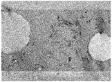
- Example 2 is a cross-sectional SEM photograph of a diffusion layer of an antiglare film obtained in Example 1.
- PETA pentaerythritol triacrylate
- DPHA dipentaerythritol hexaacrylate
- SAP cellulose acetate propionate
- a coating solution was prepared by blending 190 parts by mass of a mixture of toluene and methyl isobutyl ketone (mass ratio 8: 2) as a solvent with respect to 100 parts by mass of the radiation curable binder.
- 70 ° C. dry air was passed at a flow rate of 1.2 m / s and dried for 1 minute to form a coating film.
- the coating film was irradiated with ultraviolet rays (200 mJ / cm 2 in a nitrogen atmosphere) to cure the radiation curable binder to form a diffusion layer, and an antiglare film was produced.
- the film thickness of the diffusion layer was 6.0 ⁇ m.
- Table 1 shows the types of organic fine particles (A) and fine particles (B) to be added to the coating liquid, the types and contents of layered inorganic compounds, the presence or absence of surfactants, and the ratio of (coating liquid supply amount / coating amount).
- An antiglare film was produced in the same manner as in Example 1 except that the method was as described in 1.
- (Fine particle B) C Polystyrene particles (refractive index 1.59, average particle size 3.5 ⁇ m, manufactured by Soken Chemical Co., Ltd.)
- the particle diameter of a layered inorganic compound is the average particle diameter D50 by the laser diffraction scattering type particle size distribution measuring method.
- ⁇ Less than 20% of the observed layered inorganic compound whose major axis or major axis extension line was parallel to the major axis or major axis extension line of other layered inorganic compound ⁇ : Observed layered inorganic compound Among them, the presence of those whose major axis or major axis extension line was parallel to the major axis or major axis extension line of another layered inorganic compound is 20% or more and less than 30% x: More than 30% of the long diameter or long diameter extension line is parallel to the long diameter or long diameter extension line of other layered inorganic compounds
- the subject was installed in a room under an environment with an illuminance of approximately 1,000 Lx, displayed on a white screen, and viewed from various angles up and down and left and right from a location 1.5 to 2.0 m away from the liquid crystal television. Twenty people performed visual sensory evaluation. It was determined whether surface glare was observed on the white screen display, and evaluation was performed according to the following criteria. ⁇ : 15 or more people who answered good ⁇ : 10-14 people who answered good ⁇ : 5-9 people who answered good ⁇ : 4 or less people who answered good
- the antiglare film is cut in the thickness direction, and the SEM observation of the cross section of the diffusion layer is performed to determine the thickness of the impregnated layer formed on the cross section of the five organic fine particles (A) by 2 points each for a total of 10 points. The average value was calculated.
- the layered inorganic compound was contained in a random orientation state in the diffusion layer, and in the cross section, the talc particles had a long diameter. Is observed as a linear substance of about 0.5 to 1.5 ⁇ m, bentonite particles are observed as a linear substance of about 0.1 to 0.8 ⁇ m, and haze value, mandrel test, contrast and surface glare Each evaluation was good. Since the anti-glare film which concerns on the comparative example 1 was a thing which does not contain a layered inorganic compound in a diffused layer, it was inferior to each evaluation of a mandrel test, contrast, and surface glare.
- the antiglare film according to Comparative Example 2 has a low content of the layered inorganic compound added at the time of preparing the coating solution, is inferior in mandrel test, contrast, and surface glare evaluation, and the layered inorganic compound is in a non-random orientation state. There were many things. Moreover, the antiglare film according to Comparative Example 3 contained a large amount of the layered inorganic compound added during the preparation of the coating solution, and could not be uniformly applied to the transparent substrate. In addition, the antiglare films according to Comparative Examples 4 and 5 are inferior in each of the mandrel test, contrast, and surface glare evaluation because many of the layered inorganic compounds in the diffusion layer are not in a random orientation state. It was.
- the antiglare film of the present invention is suitable for displays such as cathode ray tube display (CRT), liquid crystal display (LCD), plasma display (PDP), electroluminescence display (ELD), touch panel, electronic paper, especially high definition display. It can be preferably used.
- displays such as cathode ray tube display (CRT), liquid crystal display (LCD), plasma display (PDP), electroluminescence display (ELD), touch panel, electronic paper, especially high definition display. It can be preferably used.
Landscapes
- Physics & Mathematics (AREA)
- General Physics & Mathematics (AREA)
- Optics & Photonics (AREA)
- Nonlinear Science (AREA)
- Mathematical Physics (AREA)
- Chemical & Material Sciences (AREA)
- Crystallography & Structural Chemistry (AREA)
- Optical Elements Other Than Lenses (AREA)
- Laminated Bodies (AREA)
- Polarising Elements (AREA)
- Liquid Crystal (AREA)
Abstract
Description
これらの防眩性フィルムは、凝集性粒子や無機及び/又は有機フィラーを樹脂中に添加して層表面に凹凸形状を形成するタイプ、あるいは層表面に凹凸をもったフィルムをラミネートして凹凸形状を転写するタイプや、2種類以上のポリマー等、バインダーを構成する化合物同士の相溶性を利用して相分離させることで凹凸形状を形成するタイプ等がある。
また、従来のタイプの防眩性フィルムは、フィルム表面に、いわゆる面ギラと呼ばれるキラキラ光る輝きが発生し、表示画面の視認性が低下するという問題もあった。
また、防眩層を構成するバインダー樹脂としては、紫外線硬化型バインダー樹脂を紫外線照射して硬化させてなるものが用いられているが、このような防眩層は、硬いが衝撃に弱いものであった。
偏光板製造工程や偏光板と液晶素子との貼合工程においては、防眩性フィルムの曲率半径を小さくしたり、局所的な加重がかかったりすることがあるが、上述の硬いが衝撃に弱い防眩層を備えた防眩性フィルムを用いると、防眩層にクラックが生ずる問題があった。更には、液晶ディスプレイとして、高い傷付き防止性が要求されるが、傷は加重により発生する局所的マイクロクラックの発生がきっかけとなるので、防眩性フィルムにはクラック耐性、すなわち耐衝撃性を有することが求められていた。
更に、紫外線硬化樹脂の重合収縮により製造した防眩性フィルムには、カールが発生することがあるという問題もあった。
このような溶剤で予め膨潤させた樹脂ビーズを用いてなる防眩層を備えた防眩性フィルムは、樹脂ビーズとバインダー樹脂との界面の密着性の向上を期待でき、防眩層の耐衝撃性の向上を図ることができるため、高精細化ディスプレイへ適用することが期待されている。
しかしながら、予め溶剤で膨潤させた樹脂ビーズを用いてなる防眩層を備えた防眩性フィルムは、防眩層中の膨潤した樹脂ビーズとバインダー樹脂との界面の密着性の向上は、該界面に生じるアンカー効果のみによるものであったため、密着性等を更に向上させる余地があった。
このため、従来の防眩性フィルムは、防眩層全体の耐衝撃性としては不充分であり、上述の偏光板製造工程等や、液晶ディスプレイに適用した際に防眩層にクラックが生じることを充分に防止できるものではなかった。
また、上記塗液は、有機微粒子(A)を膨潤する溶剤を含有することが好ましい。
また、上記塗液は、更に微粒子(B)を含有し、拡散層中の有機微粒子(A)は、放射線硬化型バインダーが含浸された含浸層を有し、かつ、上記拡散層中の微粒子(B)の平均粒径よりも大きな平均粒径を有することが好ましい。
上記微粒子(B)は、有機微粒子(A)よりも親油性が高い微粒子であることが好ましい。
また、上記放射線硬化型バインダーの屈折率と、有機微粒子(A)及び微粒子(B)の屈折率との差を、各々ΔA及びΔBとしたとき、上記ΔA及びΔBは、下記式(1)を満たすことが好ましい。
|ΔA|<|ΔB| (1)
また、本発明は、最表面に本発明の防眩性フィルム、又は、本発明の偏光板を備えることを特徴とする画像表示装置でもある。
以下、本発明を詳細に説明する。
上記光透過性基材は、平滑性、耐熱性を備え、機械的強度に優れたものが好ましい。上記光透過性基材を形成する材料の具体例としては、ポリエステル(ポリエチレンテレフタレート、ポリエチレンナフタレート)、セルローストリアセテート、セルロースジアセテート、セルロースアセテートブチレート、ポリアミド、ポリイミド、ポリエーテルスルフォン、ポリスルフォン、ポリプロピレン、ポリメチルペンテン、ポリ塩化ビニル、ポリビニルアセタール、ポリエーテルケトン、ポリメタクリル酸メチル、ポリカーボネート、又は、ポリウレタン、シクロポリオレフィン等の熱可塑性樹脂が挙げられ、好ましくはポリエステル(ポリエチレンテレフタレート、ポリエチレンナフタレート)、セルローストリアセテートが挙げられる。
また、上記光透過性基材は、その上に拡散層を形成するに際して、接着性向上のために、コロナ放電処理、プラズマ処理、鹸化処理、酸化処理等の物理的な処理のほか、アンカー剤もしくはプライマーと呼ばれる塗料の塗布を予め行ってもよい。
上記層状無機化合物としては特に限定されず、例えば、モンモリロナイト、バイデライト、ノントロナイト、サポナイト、ヘクトライト、ソーコナイト、スチブンサイト、バーミキュライト、ハロイサイト、カオリナイト、エンデライト、ディッカイト、タルク、パイロフィライト、マイカ、マーガライト、白雲母、金雲母、テトラシリリックマイカ、テニオライト、アンチゴライト、クロライト、クックアイト、ナンタイト等が挙げられる。これらの層状無機化合物は、天然物であってもよく、合成物であってもよい。また、上記層状無機化合物は、有機表面処理が施されていてもよい。
これらの層状無機化合物の粒子径は、レーザー回折散乱式粒度分布測定法による平均粒径D50(粒子径分布のメジアン径)で示される。好ましい粒径範囲は、0.1~9μm、より好ましくは0.3~5μmである。
これらの層状無機化合物は、実際の防眩性フィルムの断面をSEM等で観察した場合には、長径が0.3~5μm程度の板状粒子として存在している。本発明の課題を解決するためには、上記粒子径が小さすぎても効果を発揮できず、大きすぎても防眩性フィルム全体の透明性に影響がある場合もある。SEMで断面観察した結果に測定できる粒径で、更に好ましい範囲は長径が0.3~2.5μm程度の板状粒子である。なお、長径の測定においては、SEM断面観察にて見えた板状粒子の10点の長径の平均値を取ることとする。
上記層状無機化合物が拡散層中にランダムな配向状態で含有されていることで、上記拡散層が変形等により様々な方向から応力が加えられた場合であっても、クラックの起点となることを防止できる。また、該拡散層の作製時に紫外線照射を行っても、ランダムな配向状態で含有された上記層状無機化合物が紫外線照射によるダメージを緩和し、更に、製造した防眩性フィルムにカールが生じることも好適に防止することができる。
これは、上記層状無機化合物が、層間がファンデルワールス力で結合された多層構造を有し、該層間の結合力が弱いので、衝撃が加わると該層間がずれることにより、加えられたずり応力を吸収できることでより衝撃を吸収しやすくなるからであると類推している。また、このような層状無機化合物が上記拡散層中にランダムな配向状態で含有されていることで、拡散層のあらゆる方向から加えられる応力に対して、上述の衝撃吸収効果を発揮することが可能となる。
すなわち、本発明の防眩性フィルムは、上記層状無機化合物が拡散層中にランダムな配向状態で含有されていることで、極めて耐衝撃性に優れたものとなる。
更に、例えば、上記拡散層が後述する微粒子(B)を含有し、上記有機微粒子(A)が架橋アクリルビーズ、上記微粒子(B)がポリスチレンである場合、上記層状無機化合物がタルクであると、上記有機微粒子(A)と微粒子(B)との凝集を好適に制御することが可能となる。この結果、得られる防眩性フィルムの防眩性、白茶け防止性、面ギラ防止性を高レベルで達成することができる。
これは、上記タルクが親油性の高い物質であることが影響しているものと推測している。すなわち、有機微粒子(A)(架橋アクリル樹脂)が親水性、微粒子(B)(ポリスチレン)が親油性の各性質を有し、両微粒子が凝集するのを、親油性の高いタルクが調整しているものと推測している。
なお、上記タルクの形態としては、層状構造であり、断面顕微鏡観察において針状又は繊維状に見えるものも含む。
なお、本発明の防眩性フィルムの面ギラを抑制するために、上記有機微粒子(A)は、後述する放射線硬化型バインダーに対して屈折率差ΔAを持たせ、上記拡散層に内部拡散機能を持たせることがより好ましい。
具体的には、後述する微粒子(B)を用いない場合、上記屈折率差ΔAは0.1以下であることが好ましく、後述する微粒子(B)を用いる場合、上記屈折率差ΔAは0.04以下であることが好ましい。
上記アクリル系モノマーとして、メチルメタクリレートを用いて得られた架橋アクリル樹脂が特に好適である。
なお、上記平均粒径とは、拡散層に含有される各々の粒子が、形状が単一な粒子であれば、その粒径の算術平均を意味し、ブロードな粒度分布を持つ不定形型の粒子であれば、粒度分布測定により、最も多く存在する粒子の粒径を意味する。なお、上記粒径は、微粒子だけの状態のときは、コールターカウンター法等により計測できる。しかし、この方法以外に、硬化膜中の微粒子測定方法として、実際に作製した防眩性フィルムの断面をSEM観察し、その写真撮影による測定や、防眩性フィルム表面を透過型光学顕微鏡によって観察することによっても計測できる。
上記含浸層を有することで、上記有機微粒子(A2)は、拡散層の放射線硬化型バインダーの硬化物(以下、バインダー樹脂ともいう)との密着性が極めて優れたものとなる。また、有機微粒子(A2)における上記含浸層は、放射線硬化型バインダーが混合した状態で形成されたものであるので、上記含浸層の屈折率は、放射線硬化型バインダーの屈折率と有機微粒子(A)の屈折率との間の屈折率となり、上記有機微粒子(A2)(含浸層)とバインダー樹脂との界面での上記拡散層の透過光の反射を好適に減少することが可能となる。また、同時に、上記含浸層は適度な層厚であって、有機微粒子(A2)の中心部は初期の有機微粒子(A)の屈折率を保持しているので内部拡散が減少することがなく面ギラを好適に防止することが可能となる。
更に、後述するように、上記含浸層は、上記放射線硬化型バインダー及び/又は溶剤が、有機微粒子(A)を膨潤させることで好適に形成される層であるため、上記有機微粒子(A2)は、極めて柔軟性に富んだ微粒子となる。このため、上記拡散層の表面には該拡散層中の有機微粒子(A2)に対応する位置に形成されるが、該凸部の形状をなだらかなものとすることができる。なお、この点については、後で更に詳細に説明する。
上記含浸層は、例えば、上記拡散層の断面をSEM等で観察し、中の有機微粒子(A2)の断面を観察することで判別することができる。その詳細な方法としては、拡散層を厚さ方向に切断し、有機微粒子(A2)を1個以上少なくとも含む断面を倍率3千倍から5万倍でSEM観察を行い、放射線硬化型バインダーが有機微粒子(A2)に含浸している部分で、有機微粒子(A2)と周りの放射線硬化型バインダーとの境界が比較的明瞭であり、かつ、有機微粒子(A2)内に放射線硬化型バインダーが最も含浸していると見られる部分2点の厚さをSEM写真等で測定し、合計5個の有機微粒子(A2)について同様に測定し、10点の測定結果の平均値を算出する。仮に有機微粒子(A2)の他に、別の微粒子等を含有する場合、上記と同様にその微粒子への含浸層の厚さを測定できる。
なお、上記含浸層に含浸する放射線硬化型バインダーは、構成する全成分が含浸されたものであってもよく、構成する成分の一部が含浸したものであってもよい。
なお、上記含浸層の平均厚さとは、防眩性フィルムの断面SEM写真で観察される有機微粒子(A)の断面における含浸層の厚さの平均値を意味する。
0.01μm<DA2-DA1<1.0μm (2)
上記式(2)において、「DA2-DA1」が0.01μm以下であると、上記含浸層の厚さが薄くなりすぎ、上述した含浸層を形成することで得られる効果を得ることができないことがある。「DA2-DA1」が1.0μm以上であると、内部拡散機能が充分に発揮されなくなり、面ギラの防止効果を充分に得られないことがある。
上記「DA2-DA1」のより好ましい下限は0.1μm、より好ましい上限は0.5μmである。「DA2-DA1」がこの範囲にあることで、より前述の効果を発揮することができる。
このような微粒子(B)としては、上記塗液中の放射線硬化型バインダー及び/又は溶剤により膨潤されない粒子であることが好ましい。微粒子(B)が含浸層を有すると微粒子(B)とバインダーとの界面での拡散が減少するためである。
ここで、「膨潤されない粒子」とは、上記放射線硬化型バインダー及び/又は溶剤により全く膨潤されることがない場合のほか、僅かに膨潤される場合も含む。上記「僅かに膨潤される場合」とは、上記拡散層中において、上記微粒子(B)に上記有機微粒子(A2)と同様の含浸層が形成されるが、この含浸層の平均厚さが上記有機微粒子(A)の含浸層よりも小さく、かつ、0.1μm未満の場合をいう。
上記拡散層中の微粒子(B)に含浸層が形成されているか否かの判断は、例えば、上記拡散層の微粒子(B)の断面を顕微鏡(SEM等)で観察することで行うことができる。
なお、以下の説明において、上記拡散層中の微粒子(B)を「微粒子(B2)」ということとする。
なかでも、屈折率が高くバインダーとの屈折率差を設けやすく(通常の放射線硬化型バインダーの屈折率は1.48~1.54程度)、内部拡散を得やすいことから、ポリスチレン微粒子及び/又はアクリル-スチレン共重合体微粒子が好適に用いられる。なお、以下では微粒子(B)が有機粒子であるとして説明する。
ここで、アクリル樹脂、スチレン樹脂による有機微粒子は、一般的に知られている製造方法で製造される折、材料としてはいずれもアクリル-スチレン共重合樹脂を用いたり、コア-シェルタイプの微粒子では、コアにアクリル樹脂からなる微粒子を用いたポリスチレン微粒子や、逆にコアにスチレン樹脂からなる微粒子を用いたポリアクリル微粒子が存在する。本明細書では、アクリル微粒子、スチレン微粒子、アクリル-スチレン共重合微粒子の区別については、微粒子の持つ特性が、どの樹脂に一番近いかで判断する。例えば、微粒子の屈折率が1.50未満であればアクリル微粒子とし、1.50以上1.59未満であればアクリル-スチレン共重合体微粒子とし、1.59以上であればスチレン微粒子ととらえることができる。
1.0μm>DA2-DA1>DB2-DB1≧0 (3)
上記式(3)を満たすことで、拡散層表面の凹凸形状を滑らかなものにするとともに、内部拡散に寄与する粒子へのバインダー等の含浸による粒子の屈折率の変化が抑えられる等のため、内部拡散の維持が容易となり、かつ、粒子表面は含浸によりバインダーとの屈折率差が減じたことにより反射が抑えられるので本発明の防眩性フィルムの白茶け防止、及び、面ギラ防止をより確実にすることができる。
なお、拡散層中の微粒子(B)と放射線硬化型バインダーとの屈折率差ΔB2が大きい場合(例えば、ΔB2が0.02以上の屈折率差を有する場合)には、上記DA2は、上記DB2よりも大きいことがより好ましい。これは、有機微粒子(A)よりも内部拡散性が大きい微粒子(B)の平均粒径が小さいことによって、拡散層内部に広範囲に分布することができ、本発明の防眩性フィルムに面ギラやガサツキの発生が軽減されるためである。
このような放射線硬化型バインダーとしては、上述した有機微粒子(A)を膨潤させるものが好適に挙げられ、透明性のものが好ましく、例えば、紫外線又は電子線により硬化する電離放射線硬化型樹脂が挙げられる。なお、本明細書において「(メタ)アクリレート」とは、メタクリレート及びアクリレートを指すものである。また、本明細書において、モノマーとは、電離放射線硬化してポリマー膜となるために、このポリマー膜の基本構造の構成単位となりうる分子を全て含み、不飽和結合を有する。つまり、オリゴマーやプレポリマーが硬化膜の基本単位であれば、オリゴマーやプレポリマーも含まれる。本発明において、上記モノマーは、分子量が5000以下の小さいものが好ましい。
1の不飽和結合を有する化合物としては、例えば、エチル(メタ)アクリレート、エチルヘキシル(メタ)アクリレート、スチレン、メチルスチレン、N-ビニルピロリドン等が挙げられる。2以上の不飽和結合を有する化合物としては、例えば、ポリメチロールプロパントリ(メタ)アクリレート、ヘキサンジオールジ(メタ)アクリレート、ポリプロピレングリコールジ(メタ)アクリレート、ジエチレングリコールジ(メタ)アクリレート、ポリエチレングリコールジ(メタ)アクリレート、ビスフェノールF EO変性ジ(メタ)アクリレート、ビスフェノールA EO変性ジ(メタ)アクリレート、トリメチロールプロパントリ(メタ)アクリレート、ジペンタエリスリトールペンタ(メタ)アクリレート、イソシアヌル酸EO変性ジ(メタ)アクリレート、イソシアヌル酸EO変性トリ(メタ)アクリレート、トリメチロールプロパンPO変性トリ(メタ)アクリレート、トリメチロールプロパンEO変性トリ(メタ)アクリレート、ジトリメチロールプロパンテトラ(メタ)アクリレート、ペンタエリスリトールトリ(メタ)アクリレート、ペンタエリスリトールペンタ(メタ)アクリレート、ジペンタエリスリトールヘキサ(メタ)アクリレート、1,6-ヘキサンジオールジ(メタ)アクリレート、ネオペンチルグリコールジ(メタ)アクリレート等の多官能化合物と(メタ)アルリレート等の反応生成物(例えば、多価アルコールのポリ(メタ)アクリレートエステル)等が挙げられる。また、2以上の不飽和結合を有するウレタン(メタ)アクリレートやポリエステル(メタ)アクリレートも挙げられる。
なかでも、上記拡散層のハードコート性が重視される場合には、上記放射線硬化型バインダーは、全モノマー成分の50%(質量比)以上が3官能以上の反応基を持つアクリレートであることが好ましい。
上記光重合開始剤としては、具体例には、アセトフェノン類、ベンゾフェノン類、ミヒラーベンゾイルベンゾエート、α-アミロキシムエステル、チオキサントン類、プロピオフェノン類、ベンジル類、ベンゾイン類、アシルホスフィンオキシド類が挙げられる。また、光増感剤を混合して用いることが好ましく、その具体例としては、例えば、n-ブチルアミン、トリエチルアミン、ポリ-n-ブチルホスフィン等が挙げられる。
上記光重合開始剤の添加量は、紫外線硬化型樹脂100質量部に対して、0.1~10質量部であることが好ましい。
上記溶剤乾燥型樹脂としては、主として熱可塑性樹脂が挙げられる。上記熱可塑性樹脂としては、一般的に例示されるものが利用される。上記溶剤乾燥型樹脂の添加により、塗布面の塗膜欠陥を有効に防止することができる。
好ましい熱可塑性樹脂の具体例としては、例えば、スチレン系樹脂、(メタ)アクリル系樹脂、酢酸ビニル系樹脂、ビニルエーテル系樹脂、ハロゲン含有樹脂、脂環式オレフィン系樹脂、ポリカーボネート系樹脂、ポリエステル系樹脂、ポリアミド系樹脂、セルロース誘導体、シリコーン系樹脂、及びゴム又はエラストマー等が挙げられる。
上記熱可塑性樹脂としては、通常、非結晶性であり、かつ有機溶剤(特に複数のポリマーや硬化性化合物を溶解可能な共通溶剤)に可溶な樹脂を使用することが好ましい。特に、成形性又は製膜性、透明性や耐候性の高い樹脂、例えば、スチレン系樹脂、(メタ)アクリル系樹脂、脂環式オレフィン系樹脂、ポリエステル系樹脂、セルロース誘導体(セルロースエステル類等)等が好ましい。ことに、アクリレートモノマーとの親和性、硬度および光学特性のバランスが良いことから(メタ)アクリル系樹脂が特に好ましい。
|ΔA|<|ΔB| (1)
上記式(1)を満たすことで、有機微粒子(A)による拡散角の小さな内部拡散と微粒子(B)による拡散角の大きい内部拡散とを併せ持つ面ギラがなく画面輝度の均一性に優れた防眩フィルムを得ることができる。
なお、上記放射線硬化型バインダー、有機微粒子(A)及び微粒子(B)の屈折率の測定方法としては任意の方法が挙げられるが、例えば、ベッケ法、最小偏角法、偏角解析、モード・ライン法、エリプソメトリ法等により測定することができる。各方法は、材料そのものを測定すること以外に、作製した防眩性フィルムの膜中から微粒子をなんらかの形で取り出したものや測定方法によっては、塗膜そのものについても同様に用いることができる。
更に、上記放射線硬化型バインダーが、上記(メタ)アクリレートとそれ以外の樹脂及び添加剤とを含有する場合、上記放射線硬化型バインダーの屈折率とは、硬化後の微粒子を除いた含有する全ての樹脂成分及び添加剤による屈折率をいう。
上記屈折率の好ましい測定方法としては、放射線硬化型バインダーであれば、硬化膜からバインダー部分のみを削り取ってベッケ法で測定する方法が挙げられる。また、NTTアドバンステクノロジ社製の透過型位相シフトレーザー顕微干渉計測装置PLM-OPTを用いて位相差を測定することで、有機微粒子と樹脂成分との屈折率差を実測することができる。よって有機微粒子の屈折率については、先に求めた樹脂成分の屈折率±屈折率差という形で求める方法が挙げられる。
上記溶剤としては特に限定されず、例えば、アルコール(例、メタノール、エタノール、イソプロパノール、ブタノール、ベンジルアルコール)、ケトン(例、アセトン、メチルエチルケトン、メチルイソブチルケトン、シクロヘキサノン、シクロペンタノン)、エステル(例、酢酸メチル、酢酸エチル、酢酸プロピル、酢酸ブチル、蟻酸メチル、蟻酸エチル、蟻酸プロピル、蟻酸ブチル)、脂肪族炭化水素(例、ヘキサン、シクロヘキサン)、ハロゲン化炭化水素(例、メチレンクロライド、クロロホルム、四塩化炭素)、芳香族炭化水素(例、ベンゼン、トルエン、キシレン)、アミド(例、ジメチルホルムアミド、ジメチルアセトアミド、n-メチルピロリドン)、エーテル(例、ジエチルエーテル、ジオキサン、テトラヒドロフラン)、エーテルアルコール(例、1-メトキシ-2-プロパノール)等が挙げられる。
なお、上記有機微粒子(A)の含浸層の形成は、該有機微粒子(A)を膨潤させる性質を持つ溶剤が存在することで、上記放射線硬化型バインダーの膨潤性の程度によらず、より確実に行うことができるので、少なくとも上記溶剤は、上記有機微粒子(A)を膨潤させる性質を持つことがより好ましい。これは、上記有機微粒子(A)に、まず、上記溶剤が作用して上記有機微粒子(A)が膨潤し、次いで上記放射線硬化バインダーに含まれる低分子量成分が含浸してゆくためであると類推している。
本発明の防眩性フィルムでは、上記放射線硬化型バインダー及び溶剤の組み合わせとしては、なかでも、放射線硬化型バインダーとして、分子量が小さく含浸しやすいことから(メタ)アクリレートモノマーと、溶剤として、上記有機微粒子(A)を膨潤させる性質の強いケトン及び/又はエステル系とを組み合わせて用いることが好ましい。
また、上記溶剤を混合して用いることで有機微粒子(A)の膨潤度合いを調整することにより、上記放射線硬化型バインダーに含まれる低分子量成分の含浸量を制御することができる。
なお、光透過性基材としてセルローストリアセテート(以下、TAC基材ともいう)を使用する場合は、光透過性基材への拡散層の界面密着性や界面で生じる干渉縞防止のために、上記TAC基材を膨潤させ、かつ、TAC基材中に溶剤及び樹脂成分中の低分子量成分を含浸させることができるような溶剤を使用することが好ましい。有機微粒子(A)膨潤のために用いる溶剤と、TAC基材に含浸するような溶剤は、共通であるとなおよい。つまり、TAC基材への溶剤と、予め含浸層を有する有機微粒子(A)を調製する場合に用いる溶剤とがほぼ同じであると、上記塗液が含有する化合物バランスが非常に安定した状態となり、長時間、防眩性フィルムを加工する場合でも安定加工できる、優れた塗液とすることができる。
そのような溶剤として好ましいのは、メチルイソブチルケトン等である。また、樹脂成分中の低分子量成分として好ましいのは、ペンタエリスリトールトリ(メタ)アクリレート、ペンタエリスリトールペンタ(メタ)アクリレート、ジペンタエリスリトールペンタ(メタ)アクリレート、ジペンタエリスリトールヘキサ(メタ)アクリレート等である。
上記各材料を混合し塗液を調製する方法としては特に限定されず、例えば、ペイントシェーカー又はビーズミル等を使用するとよい。
上記塗液の塗布方法としては特に限定されず、例えば、ロールコート法、ミヤバーコート法、グラビアコート法、ダイコート法等が挙げられる。
上記拡散層の厚さは、拡散層の断面SEM観察などで測定できる。測定する場合には、有機微粒子(A2)が存在しない拡散層表面位置から光透過性基材界面までの厚さを5点以上測定し、その平均値を求める。
上記塗膜の硬化方法としては特に限定されないが、紫外線照射によって行うことが好ましい。紫外線によって硬化を行う場合、190~380nmの波長域の紫外線を使用することが好ましい。紫外線による硬化は、例えば、メタルハライドランプ灯、高圧水銀灯、低圧水銀灯、超高圧水銀灯、カーボンアーク灯、ブラックライト蛍光灯等によって行うことができる。電子線源の具体例としては、コッククロフトワルト型、バンデグラフト型、共振変圧器型、絶縁コア変圧器型、直線型、ダイナミトロン型、高周波型等の各種電子線加速器が挙げられる。
また、塗液にフッ素系、シロキサン系等の界面活性剤を0.0002~2.0質量%添加することがランダムな配向状態を得るためにはより好ましい。乾燥時の対流をより効果的に抑えることで、対流による配向を防止できるからである。添加量が0.0002質量%未満では対流の抑制効果が不充分になり、2.0質量%を超えると、形成する拡散層の硬度や擦傷性等の低下が生じることがある。
上記拡散層は、該拡散層中の少なくとも有機微粒子(A)に対応する位置に凸部(以下凸部(A)ともいう)を有することが好ましい。
また、有機微粒子(A)が上述した含浸層を有する有機微粒子(A2)である場合、上記凸部(A)は、その高さ及び/又は平均傾斜角が、下記要件(1)、(2)及び(3)の全てを充足する有機微粒子(C)を含む拡散層(C)の表面の上記有機微粒子(C)に対応する位置の凸部(以下、凸部(C)ともいう)の高さ及び/又は平均傾斜角よりも低いことが好ましい。
要件(1):有機微粒子(A)に代えて有機微粒子(C)を用いる以外は、有機微粒子(A)を含有する拡散層と同条件で、拡散層(C)を形成する
要件(2):拡散層(C)中の有機微粒子(C)は、拡散層中の有機微粒子(A)と同じ平均粒径を有する
要件(3):有機微粒子(C)は、拡散層(C)中で含浸層が形成されない
これは、上記有機微粒子(A2)が、上記有機微粒子(C)と比較して、非常に柔軟性に富んだ微粒子であるからと考えられる。すなわち、上記塗膜を硬化させると、放射線硬化型バインダーは硬化収縮を起こすが、上記有機微粒子(A2)が位置する表面の硬化収縮は、該有機微粒子(A2)の位置しない表面の硬化収縮と比較して、上記放射線硬化型バインダー量が少ないため小さくなる。また、上記有機微粒子(A2)は、非常に柔軟性に富んだ微粒子であるため、上記塗膜の硬化収縮により有機微粒子(A2)が変形する。その結果、形成される凸部(A)の高さ及び/又は平均傾斜角が、より硬い有機微粒子(C)を含む拡散層(C)の表面に形成される上記凸部(C)と比較して低く、滑らかになるものと推測している。
なお、上記凸部の高さとは、防眩性フィルム表面をAFMにより観察し、表面に存在する凸部と、該凸部に隣接する他の凸部との間の凹部との差を凸部の高さn(nは1~10)として測定する。そして、このように求めた任意の凸部高さ10点を平均して求めたものである。
すなわち、本発明の防眩性フィルムは、上記層状無機化合物が拡散層中にランダムな配向状態で含有されていることで、極めて耐衝撃性に優れたものとなる。
更に、上記有機微粒子(A2)を含有する拡散層を備えた本発明の防眩性フィルムは、変形等による様々な方向からの応力による歪みがたまり辛いので、該拡散層中の有機微粒子(A2)と放射線硬化型バインダーの硬化物との密着性が極めて優れたものとなる。なお、本発明の防眩性フィルムは、マンドレル試験で、マンドレルの直径が10mmの条件において、より好ましくは8mmの条件において、更に好ましくは6mmの条件においてクラックが生じないものであることが好ましい。
また、上記拡散層中の有機微粒子(A2)には上述した含浸層が形成されており、該含浸層は、放射線硬化型バインダーが混合された状態で形成されたものであるので、上記拡散層は、上記拡散層中の有機微粒子(A)(含浸層)と放射線硬化型バインダーの硬化物との屈折率差が減少し、界面での反射を好適に減少できる。また、同時に、上記含浸層は適度な層厚であって、有機微粒子(A)の中心は、初期の有機微粒子(A)の屈折率を保持しているので、適度な内部拡散性を発現することができ、面ギラを好適に防止できる。
更に、上記拡散層の有機微粒子(A)に対応する位置に形成された凸部を、その高さが低く、なだらかな形状とすることができる。
そのため、本発明の防眩性フィルムの防眩性、白茶け防止性及び面ギラ防止性を高いレベルで達成することができる。
なお、上記ヘイズ値は、JIS-K7136に規定されたヘイズ(曇度)に準じ、ヘイズメーターHR100(村上色彩技術研究所社製、商品名)を用いて測定した値である。なお、本発明におけるヘイズ値は、全てこの方法で測定した値である。
すなわち、本発明の防眩性フィルムの製造方法は、光透過性基材と、該光透過性基材の少なくとも一方の面上に形成され、表面に凹凸形状を有する拡散層とを有する防眩性フィルムの製造方法であって、上記光透過性基材の少なくとも一方の面上に、層状無機化合物、有機微粒子(A)、及び、(メタ)アクリレートモノマーを必須成分として含む放射線硬化型バインダーを含有する塗液を塗布し、乾燥させて塗膜を形成し、該塗膜を硬化させて前記拡散層を形成する工程を有し、上記拡散層中の上記層状無機化合物は、ランダムな配向状態で含有されていることを特徴とするものである。
また、上記拡散層を形成する工程も、上述した本発明の防眩性フィルムにおいて説明した方法と同様の方法が挙げられる。
まず、光透過性基材としてトリアセチルセルロース(富士フィルム(株)製、厚さ80μm)を用意した。
次に、放射線硬化型バインダーとして、ペンタエリスリトールトリアクリレート(PETA)、ジペンタエリスリトールヘキサアクリレート(DPHA)、及びセルロースアセテートプロピオネート(SAP)の混合物(質量比;PETA/DPHA/SAP=82/7/11)を用い(屈折率1.51)、光重合開始剤として1-ヒドロキシ-シクロヘキシル-フェニル-ケトン:イルガキュア184(BASF社製)を用い(バインダー固形分100質量部に対し、3質量部)、これに有機微粒子(A)として、低架橋アクリル粒子(屈折率1.49、平均粒径5.0μm)を、放射線硬化型バインダー100質量部に対して、6.0質量部、微粒子(B)として、ポリスチレン粒子(屈折率1.59、平均粒径3.5μm)を、放射線硬化型バインダー100質量部に対して、5.0質量部、層状無機化合物として、タルク粒子(屈折率1.57、平均粒径0.8μm)を、放射線硬化型バインダー100質量部に対して、8.0質量部含有させた。更に、界面活性剤として非反応性フッ素系界面活性剤を、放射線硬化型バインダー100質量部に対して、0.003質量部添加した。これに溶剤としてトルエンとメチルイソブチルケトンの混合物(質量比8:2)を、放射線硬化型バインダー100質量部に対して、190質量部配合した塗液を調製した。
得られた塗液を、塗液供給量と塗布量が一致する(塗液供給量/塗布量=1.0)ように調整することでシェアーを無くして光透過性基材にグラビア法で塗工し、1.2m/sの流速で70℃の乾燥空気を流通させ、1分間乾燥させて塗膜を形成した。
その後、塗膜に紫外線を照射して(窒素雰囲気下にて200mJ/cm2)放射線硬化型バインダーを硬化させて拡散層を形成し、防眩性フィルムを作製した。なお、拡散層の膜厚は6.0μmとした。
塗液に添加する、有機微粒子(A)及び微粒子(B)の種類、層状無機化合物の種類及び含有量、界面活性剤の有無、並びに、(塗液供給量/塗布量)の比を表1に示したようにした以外は、実施例1と同様にして防眩性フィルムを作製した。
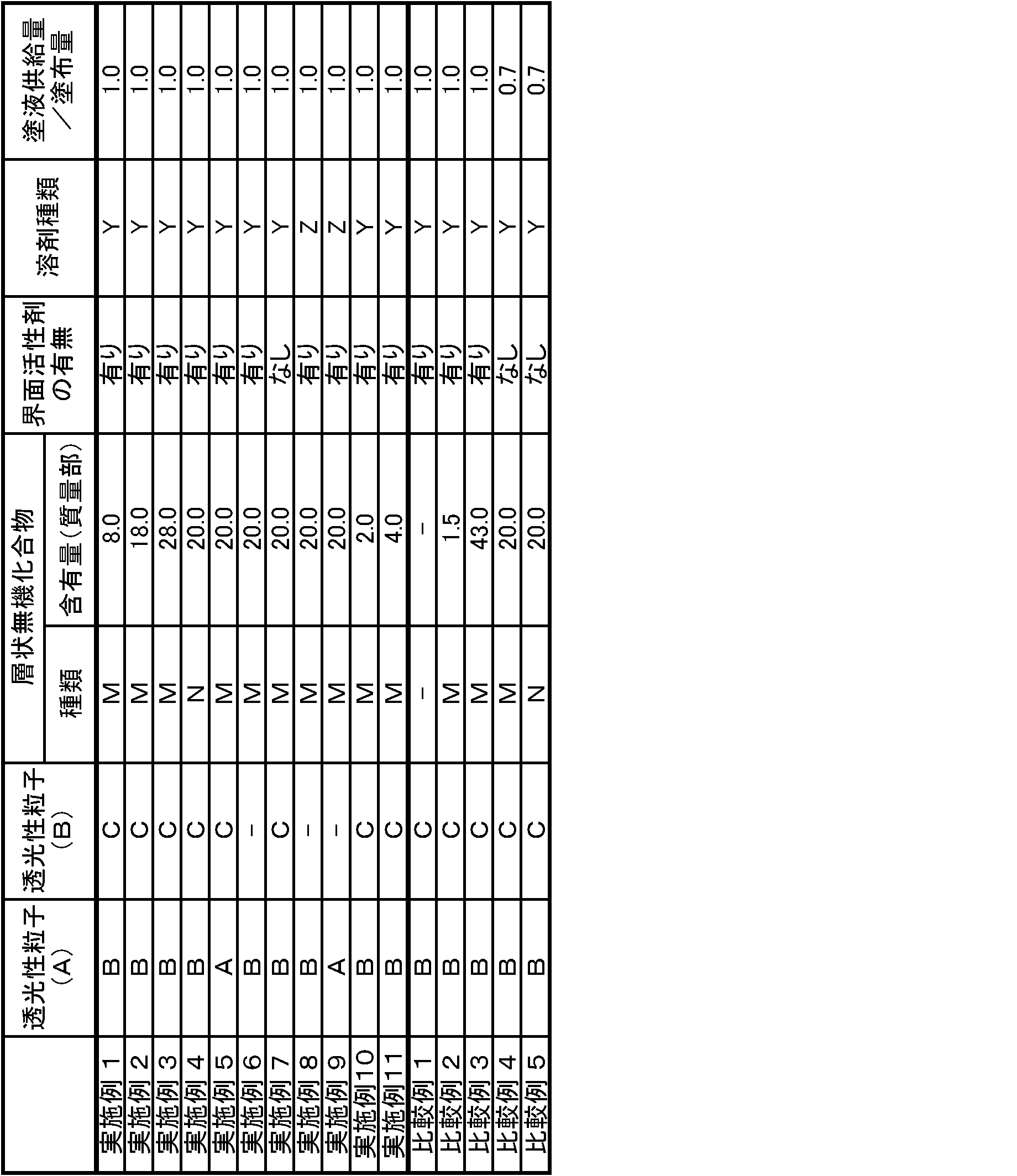
A:高架橋アクリル粒子(屈折率1.49、平均粒径5.0μm、綜研化学社製)
B:低架橋アクリル粒子(屈折率1.49、平均粒径5.0μm、綜研化学社製)
C:ポリスチレン粒子(屈折率1.59、平均粒径3.5μm、綜研化学社製)
M:タルク(屈折率1.57、平均粒径 0.8μm、ナノタルク 日本タルク社製)
N:ベントナイト(屈折率1.52、平均粒径0.1~0.5μm、クニピアF クニミネ工業社製)
なお、層状無機化合物の粒子径は、レーザー回折散乱式粒度分布測定法による平均粒径D50である。
Y:トルエンとメチルイソブチルケトンの混合物(質量比8:2)
Z:トルエンとイソプロピルアルコールの混合物(質量比7:3)
実施例及び比較例で得られた防眩性フィルムを厚さ方向に切断し、拡散層の断面において、該拡散層の厚みと該厚み方向に対して垂直方向(10μm)とが形成する領域のSEM観察にて層状無機化合物の配向状態を評価した。なお、図1に実施例1に係る防眩性フィルムの拡散層の断面SEM写真を示した。
◎:観察した層状無機化合物のうち、その長径ないし長径の延長線が、他の層状無機化合物の長径ないし長径の延長線と平行になっていたものの存在が20%未満
○:観察した層状無機化合物のうち、その長径ないし長径の延長線が、他の層状無機化合物の長径ないし長径の延長線と平行になっていたものの存在が20%以上30%未満
×:観察した層状無機化合物のうち、その長径ないし長径の延長線が、他の層状無機化合物の長径ないし長径の延長線と平行になっていたものの存在が30%以上
JIS-K7136に規定されたヘイズ(曇度)に準じ、ヘイズメーターHR100(村上色彩技術研究所社製)を用いて、実施例及び比較例で得られた防眩性フィルムのヘイズ値を測定した。
JIS K5600に準じ、マンドレルのφ6mm、φ8mm及びφ10mmで実施例及び比較例で得られた防眩性フィルムのマンドレル試験を行い、以下の基準に従って評価した。
◎:φ6mmでクラックが生じない
○:φ8mmでクラックが生じない
△:φ10mmでクラックが生じない
×:φ10mmでクラックが生じる
黒色アクリル板に実施例及び比較例で得られた防眩性フィルムを、光学フィルム用透明粘着フィルムを用いて貼合し、防眩性フィルムの表面状態を、20名の被験者が、1000Lxの明室条件で様々な方向から目視官能評価を行った。艶のある黒色を再現することができるか否かを判定し、以下の基準により評価した。
◎:良好と答えた人が15人以上
○:良好と答えた人が10~14人
△:良好と答えた人が5~9人
×:良好と答えた人が4人以下
ソニー社製液晶テレビ「KDL-40X2500」の最表面の偏光板を剥離し、表面塗布のない偏光板を貼付した。
次いで、その上に実施例及び比較例で得られた防眩性フィルムを、拡散層側が最表面となるように、光学フィルム用透明粘着フィルム(全光線透過率91%以上、ヘイズ0.3%以下、膜厚20~50μmの製品、例えばMHMシリーズ:日栄化工(株)製等)により貼付した。
該液晶テレビを、照度が約1,000Lxの環境下の室内に設置し、白画面表示して、液晶テレビから1.5~2.0m程度離れた場所から上下、左右様々な角度から、被験者20人が目視官能評価を行った。白画面表示に面ギラが認められるか否かを判定し、以下の基準に従って評価した。
◎:良好と答えた人が15人以上
○:良好と答えた人が10~14人
△:良好と答えた人が5~9人
×:良好と答えた人が4人以下
防眩性フィルムを厚さ方向に切断し、拡散層の断面のSEM観察にて、5個の有機微粒子(A)の断面に形成された含浸層の厚さを、それぞれ2点ずつ合計10点測定し、その平均値を算出した。

比較例1に係る防眩性フィルムは、拡散層中に層状無機化合物を含有しないものであったため、マンドレル試験、コントラスト及び面ギラの各評価に劣っていた。比較例2に係る防眩性フィルムは、塗液調製時に添加した層状無機化合物の含有量が少なく、マンドレル試験、コントラスト及び面ギラの各評価が劣り、また、層状無機化合物もランダムでない配向状態なものが多く存在した。また、比較例3に係る防眩性フィルムは、塗液調製時に添加した層状無機化合物の含有量が多く、透明性基材に均一な塗布ができなかった。また、比較例4及び5に係る防眩性フィルムは、拡散層中の層状無機化合物の多くがランダムな配向状態となっておらず、マンドレル試験、コントラスト及び面ギラの各評価に劣るものであった。
Claims (9)
- 光透過性基材と、該光透過性基材の少なくとも一方の面上に形成され、表面に凹凸形状を有する拡散層とを有する防眩性フィルムであって、
前記拡散層は、層状無機化合物、有機微粒子(A)、及び、(メタ)アクリレートモノマーを必須成分として含む放射線硬化型バインダーを含有する塗液を、前記光透過性基材の少なくとも一方の面上に塗布、乾燥して塗膜を形成し、該塗膜を硬化させてなるものであり、
前記塗液中の前記層状無機化合物の含有量が、前記放射線硬化型バインダー100質量部に対して2~40質量部であり、
前記層状無機化合物は、前記拡散層中にランダムな配向状態で含有されている
ことを特徴とする防眩性フィルム。 - 層状無機化合物は、タルクであることを特徴とする請求項1記載の防眩性フィルム。
- 塗液は、有機微粒子(A)を膨潤する溶剤を含有することを特徴とする請求項1又は2記載の防眩性フィルム。
- 塗液は、更に微粒子(B)を含有し、拡散層中の有機微粒子(A)は、放射線硬化型バインダーが含浸された含浸層を有し、かつ、前記拡散層中の微粒子(B)の平均粒径よりも大きな平均粒径を有することを特徴とする請求項1、2又は3記載の防眩性フィルム。
- 微粒子(B)は、有機微粒子(A)よりも親油性が高い微粒子であることを特徴とする請求項4記載の防眩性フィルム。
- 放射線硬化型バインダーの屈折率と、有機微粒子(A)及び微粒子(B)の屈折率との差を、各々ΔA及びΔBとしたとき、前記ΔA及びΔBは、下記式(1)を満たすことを特徴とする請求項4又は5記載の防眩性フィルム。
|ΔA|<|ΔB| (1) - 光透過性基材と、該光透過性基材の少なくとも一方の面上に形成され、表面に凹凸形状を有する拡散層とを有する防眩性フィルムの製造方法であって、
前記光透過性基材の少なくとも一方の面上に、層状無機化合物、有機微粒子(A)、及び、(メタ)アクリレートモノマーを必須成分として含む放射線硬化型バインダーを含有する塗液を塗布し、乾燥させて塗膜を形成し、該塗膜を硬化させて前記拡散層を形成する工程を有し、
前記拡散層中の前記層状無機化合物は、ランダムな配向状態で含有されている
ことを特徴とする防眩性フィルムの製造方法。 - 偏光素子を備えてなる偏光板であって、
前記偏光素子の表面に請求項1、2、3、4、5又は6記載の防眩性フィルムを備えることを特徴とする偏光板。 - 最表面に請求項1、2、3、4、5若しくは6記載の防眩性フィルム、又は、請求項8記載の偏光板を備えることを特徴とする画像表示装置。
Priority Applications (3)
| Application Number | Priority Date | Filing Date | Title |
|---|---|---|---|
| KR1020147016447A KR101476964B1 (ko) | 2010-03-31 | 2011-03-25 | 방현성 필름, 방현성 필름의 제조 방법, 편광판 및 화상 표시 장치 |
| CN201180016716.5A CN102822701B (zh) | 2010-03-31 | 2011-03-25 | 防眩性膜、防眩性膜的制造方法、偏振片和图像显示装置 |
| KR1020127028028A KR20130040840A (ko) | 2010-03-31 | 2011-03-25 | 방현성 필름, 방현성 필름의 제조 방법, 편광판 및 화상 표시 장치 |
Applications Claiming Priority (2)
| Application Number | Priority Date | Filing Date | Title |
|---|---|---|---|
| JP2010084010A JP4893840B2 (ja) | 2010-03-31 | 2010-03-31 | 防眩性フィルム、防眩性フィルムの製造方法、偏光板及び画像表示装置 |
| JP2010-084010 | 2010-03-31 |
Publications (1)
| Publication Number | Publication Date |
|---|---|
| WO2011122483A1 true WO2011122483A1 (ja) | 2011-10-06 |
Family
ID=44712190
Family Applications (1)
| Application Number | Title | Priority Date | Filing Date |
|---|---|---|---|
| PCT/JP2011/057397 Ceased WO2011122483A1 (ja) | 2010-03-31 | 2011-03-25 | 防眩性フィルム、防眩性フィルムの製造方法、偏光板及び画像表示装置 |
Country Status (5)
| Country | Link |
|---|---|
| JP (1) | JP4893840B2 (ja) |
| KR (2) | KR101476964B1 (ja) |
| CN (2) | CN104267450B (ja) |
| TW (2) | TWI459041B (ja) |
| WO (1) | WO2011122483A1 (ja) |
Cited By (2)
| Publication number | Priority date | Publication date | Assignee | Title |
|---|---|---|---|---|
| JP2013105160A (ja) * | 2011-11-16 | 2013-05-30 | Fujifilm Corp | 光学フィルム、偏光板、画像表示装置、及び光学フィルムの製造方法 |
| TWI615641B (zh) * | 2013-07-05 | 2018-02-21 | 鐘化股份有限公司 | 太陽能電池模組及其製造方法 |
Families Citing this family (13)
| Publication number | Priority date | Publication date | Assignee | Title |
|---|---|---|---|---|
| CN103140778B (zh) * | 2010-10-04 | 2015-10-07 | 大日本印刷株式会社 | 防眩性膜、防眩性膜的制造方法、偏振片和图像显示装置 |
| US9618656B2 (en) * | 2010-10-04 | 2017-04-11 | Dai Nippon Printing Co., Ltd. | Anti-glare film, method for producing anti-glare film, polarizer and image display device |
| US20160266286A1 (en) * | 2013-09-16 | 2016-09-15 | Coelux S.R.L. | Composite system comprising a polymer matrix and core-shell nanoparticles, process for preparing it and use thereof |
| TWI628457B (zh) * | 2014-04-17 | 2018-07-01 | 日商大日本印刷股份有限公司 | 防眩膜、偏光板、液晶面板以及影像顯示裝置 |
| CN104777544B (zh) * | 2015-04-29 | 2017-08-11 | 深圳市华星光电技术有限公司 | 偏光片及其制备方法、液晶面板 |
| JP6647761B2 (ja) * | 2015-12-07 | 2020-02-14 | 恵和株式会社 | 上用光拡散シート及びバックライトユニット |
| US11306216B2 (en) | 2016-02-09 | 2022-04-19 | Sun Chemical Corporation | High molecular weight polystyrene in inks and coatings |
| JP7069020B2 (ja) * | 2016-02-09 | 2022-05-17 | サン ケミカル コーポレイション | インキおよびコーティング中の高分子量のポリスチレン |
| KR101988548B1 (ko) | 2016-12-12 | 2019-06-12 | 주식회사 엘지화학 | 광학 필름 및 이를 포함하는 화상 표시 장치 |
| KR101988549B1 (ko) | 2016-12-12 | 2019-06-12 | 주식회사 엘지화학 | 광학 필름 및 이를 포함하는 화상 표시 장치 |
| JP2020190686A (ja) * | 2019-05-23 | 2020-11-26 | コニカミノルタ株式会社 | 光学フィルム及び光学フィルムの製造方法 |
| JP7469109B2 (ja) * | 2020-03-31 | 2024-04-16 | 日東電工株式会社 | 光学用粘着剤組成物及び光学積層体 |
| JP7526020B2 (ja) * | 2020-03-31 | 2024-07-31 | 日東電工株式会社 | 光学積層体 |
Citations (2)
| Publication number | Priority date | Publication date | Assignee | Title |
|---|---|---|---|---|
| JP2006276839A (ja) * | 2005-03-03 | 2006-10-12 | Fuji Photo Film Co Ltd | 光学機能フィルム、その製造方法、並びにそれを用いた偏光板及び画像表示装置 |
| JP2007293301A (ja) * | 2006-03-29 | 2007-11-08 | Fujifilm Corp | 光学フィルム、偏光板、画像表示装置、及び光学フィルムの製造方法 |
Family Cites Families (19)
| Publication number | Priority date | Publication date | Assignee | Title |
|---|---|---|---|---|
| JPH0721095B2 (ja) * | 1989-11-13 | 1995-03-08 | ライオン株式会社 | アクリル系樹脂組成物 |
| JPH04198248A (ja) * | 1990-11-26 | 1992-07-17 | Lion Corp | アクリル系樹脂組成物 |
| US6958860B2 (en) * | 2002-10-07 | 2005-10-25 | Eastman Kodak Company | Voided polymer film containing layered particulates |
| US20060144514A1 (en) * | 2005-01-03 | 2006-07-06 | Yongcai Wang | Polarizing plate laminated with an improved glue composition and a method of manufacturing the same |
| JP4855781B2 (ja) * | 2005-02-01 | 2012-01-18 | 日東電工株式会社 | 反射防止ハードコートフィルム、光学素子および画像表示装置 |
| JP2006301169A (ja) * | 2005-04-19 | 2006-11-02 | Konica Minolta Opto Inc | 液晶表示装置、液晶表示装置の製造方法、及びそれに用いる粘着層 |
| JP2007233374A (ja) * | 2006-02-02 | 2007-09-13 | Fujifilm Corp | ハードコートフィルム、これを用いた偏光板および画像表示装置 |
| JP2007233375A (ja) * | 2006-02-02 | 2007-09-13 | Fujifilm Corp | 反射防止フィルム、これを用いた偏光板および画像表示装置 |
| JP2007249191A (ja) * | 2006-02-17 | 2007-09-27 | Fujifilm Corp | 光学フィルム、反射防止フィルム、偏光板、及び画像表示装置 |
| US7848021B2 (en) * | 2006-02-17 | 2010-12-07 | Fujifilm Corporation | Optical film, antireflection film, polarizing plate and image display device |
| JP2007264113A (ja) * | 2006-03-27 | 2007-10-11 | Fujifilm Corp | 光学フィルム、偏光板および画像表示装置 |
| JP4145332B2 (ja) * | 2006-03-28 | 2008-09-03 | 日東電工株式会社 | ハードコートフィルム、ハードコートフィルムの製造方法、光学素子および画像表示装置 |
| US7960018B2 (en) * | 2006-03-29 | 2011-06-14 | Fujifilm Corporation | Optical film, polarizing plate, image display, and manufacturing method of optical film |
| JP5252811B2 (ja) * | 2006-05-16 | 2013-07-31 | 日東電工株式会社 | 防眩性ハードコートフィルム、偏光板および画像表示装置 |
| JP5220286B2 (ja) * | 2006-06-15 | 2013-06-26 | 日東電工株式会社 | 防眩性ハードコートフィルム、それを用いた偏光板および画像表示装置 |
| JP4281785B2 (ja) * | 2006-08-28 | 2009-06-17 | 住友化学株式会社 | 光拡散板 |
| JP2008304638A (ja) * | 2007-06-06 | 2008-12-18 | Sony Corp | 防眩性フィルムおよびその製造方法、偏光子ならびに表示装置 |
| JP2009020288A (ja) * | 2007-07-11 | 2009-01-29 | Sony Corp | 防眩性フィルムおよびその製造方法、偏光子ならびに表示装置 |
| JP2009156938A (ja) * | 2007-12-25 | 2009-07-16 | Sumitomo Chemical Co Ltd | 防眩フィルム、防眩性偏光板および画像表示装置 |
-
2010
- 2010-03-31 JP JP2010084010A patent/JP4893840B2/ja active Active
-
2011
- 2011-03-25 KR KR1020147016447A patent/KR101476964B1/ko active Active
- 2011-03-25 CN CN201410452995.5A patent/CN104267450B/zh active Active
- 2011-03-25 CN CN201180016716.5A patent/CN102822701B/zh active Active
- 2011-03-25 KR KR1020127028028A patent/KR20130040840A/ko not_active Ceased
- 2011-03-25 WO PCT/JP2011/057397 patent/WO2011122483A1/ja not_active Ceased
- 2011-03-30 TW TW100110890A patent/TWI459041B/zh active
- 2011-03-30 TW TW103132718A patent/TWI628247B/zh active
Patent Citations (2)
| Publication number | Priority date | Publication date | Assignee | Title |
|---|---|---|---|---|
| JP2006276839A (ja) * | 2005-03-03 | 2006-10-12 | Fuji Photo Film Co Ltd | 光学機能フィルム、その製造方法、並びにそれを用いた偏光板及び画像表示装置 |
| JP2007293301A (ja) * | 2006-03-29 | 2007-11-08 | Fujifilm Corp | 光学フィルム、偏光板、画像表示装置、及び光学フィルムの製造方法 |
Cited By (2)
| Publication number | Priority date | Publication date | Assignee | Title |
|---|---|---|---|---|
| JP2013105160A (ja) * | 2011-11-16 | 2013-05-30 | Fujifilm Corp | 光学フィルム、偏光板、画像表示装置、及び光学フィルムの製造方法 |
| TWI615641B (zh) * | 2013-07-05 | 2018-02-21 | 鐘化股份有限公司 | 太陽能電池模組及其製造方法 |
Also Published As
| Publication number | Publication date |
|---|---|
| KR20140079876A (ko) | 2014-06-27 |
| TWI459041B (zh) | 2014-11-01 |
| CN104267450B (zh) | 2016-08-24 |
| KR20130040840A (ko) | 2013-04-24 |
| CN104267450A (zh) | 2015-01-07 |
| CN102822701A (zh) | 2012-12-12 |
| JP2011215393A (ja) | 2011-10-27 |
| CN102822701B (zh) | 2015-08-26 |
| TW201213882A (en) | 2012-04-01 |
| TWI628247B (zh) | 2018-07-01 |
| KR101476964B1 (ko) | 2014-12-24 |
| TW201500491A (zh) | 2015-01-01 |
| JP4893840B2 (ja) | 2012-03-07 |
Similar Documents
| Publication | Publication Date | Title |
|---|---|---|
| JP4893840B2 (ja) | 防眩性フィルム、防眩性フィルムの製造方法、偏光板及び画像表示装置 | |
| JP5008734B2 (ja) | 防眩性フィルム、防眩性フィルムの製造方法、偏光板及び画像表示装置 | |
| JP4788830B1 (ja) | 防眩性フィルム、防眩性フィルムの製造方法、偏光板及び画像表示装置 | |
| JP5979000B2 (ja) | 防眩性フィルム、防眩性フィルムの製造方法、偏光板及び画像表示装置 | |
| JP5120490B2 (ja) | 防眩性フィルム、防眩性フィルムの製造方法、偏光板及び画像表示装置 | |
| JP5979002B2 (ja) | 防眩性フィルム、防眩性フィルムの製造方法、偏光板及び画像表示装置 | |
| JP5979001B2 (ja) | 防眩性フィルム、防眩性フィルムの製造方法、偏光板及び画像表示装置 | |
| JP2011197677A (ja) | 防眩性フィルム、防眩性フィルムの製造方法、偏光板及び画像表示装置 |
Legal Events
| Date | Code | Title | Description |
|---|---|---|---|
| WWE | Wipo information: entry into national phase |
Ref document number: 201180016716.5 Country of ref document: CN |
|
| 121 | Ep: the epo has been informed by wipo that ep was designated in this application |
Ref document number: 11762714 Country of ref document: EP Kind code of ref document: A1 |
|
| NENP | Non-entry into the national phase |
Ref country code: DE |
|
| ENP | Entry into the national phase |
Ref document number: 20127028028 Country of ref document: KR Kind code of ref document: A |
|
| 122 | Ep: pct application non-entry in european phase |
Ref document number: 11762714 Country of ref document: EP Kind code of ref document: A1 |