WO2011122453A1 - バスバー、及びバスバーの製造方法 - Google Patents
バスバー、及びバスバーの製造方法 Download PDFInfo
- Publication number
- WO2011122453A1 WO2011122453A1 PCT/JP2011/057255 JP2011057255W WO2011122453A1 WO 2011122453 A1 WO2011122453 A1 WO 2011122453A1 JP 2011057255 W JP2011057255 W JP 2011057255W WO 2011122453 A1 WO2011122453 A1 WO 2011122453A1
- Authority
- WO
- WIPO (PCT)
- Prior art keywords
- bus bar
- terminal
- electrode connection
- connection portion
- negative electrode
- Prior art date
- Legal status (The legal status is an assumption and is not a legal conclusion. Google has not performed a legal analysis and makes no representation as to the accuracy of the status listed.)
- Ceased
Links
Images





Classifications
-
- H—ELECTRICITY
- H01—ELECTRIC ELEMENTS
- H01M—PROCESSES OR MEANS, e.g. BATTERIES, FOR THE DIRECT CONVERSION OF CHEMICAL ENERGY INTO ELECTRICAL ENERGY
- H01M50/00—Constructional details or processes of manufacture of the non-active parts of electrochemical cells other than fuel cells, e.g. hybrid cells
- H01M50/50—Current conducting connections for cells or batteries
- H01M50/543—Terminals
-
- H—ELECTRICITY
- H01—ELECTRIC ELEMENTS
- H01M—PROCESSES OR MEANS, e.g. BATTERIES, FOR THE DIRECT CONVERSION OF CHEMICAL ENERGY INTO ELECTRICAL ENERGY
- H01M50/00—Constructional details or processes of manufacture of the non-active parts of electrochemical cells other than fuel cells, e.g. hybrid cells
- H01M50/50—Current conducting connections for cells or batteries
- H01M50/571—Methods or arrangements for affording protection against corrosion; Selection of materials therefor
-
- H—ELECTRICITY
- H01—ELECTRIC ELEMENTS
- H01M—PROCESSES OR MEANS, e.g. BATTERIES, FOR THE DIRECT CONVERSION OF CHEMICAL ENERGY INTO ELECTRICAL ENERGY
- H01M50/00—Constructional details or processes of manufacture of the non-active parts of electrochemical cells other than fuel cells, e.g. hybrid cells
- H01M50/50—Current conducting connections for cells or batteries
-
- H—ELECTRICITY
- H01—ELECTRIC ELEMENTS
- H01M—PROCESSES OR MEANS, e.g. BATTERIES, FOR THE DIRECT CONVERSION OF CHEMICAL ENERGY INTO ELECTRICAL ENERGY
- H01M50/00—Constructional details or processes of manufacture of the non-active parts of electrochemical cells other than fuel cells, e.g. hybrid cells
- H01M50/50—Current conducting connections for cells or batteries
- H01M50/502—Interconnectors for connecting terminals of adjacent batteries; Interconnectors for connecting cells outside a battery casing
-
- H—ELECTRICITY
- H01—ELECTRIC ELEMENTS
- H01M—PROCESSES OR MEANS, e.g. BATTERIES, FOR THE DIRECT CONVERSION OF CHEMICAL ENERGY INTO ELECTRICAL ENERGY
- H01M50/00—Constructional details or processes of manufacture of the non-active parts of electrochemical cells other than fuel cells, e.g. hybrid cells
- H01M50/50—Current conducting connections for cells or batteries
- H01M50/502—Interconnectors for connecting terminals of adjacent batteries; Interconnectors for connecting cells outside a battery casing
- H01M50/507—Interconnectors for connecting terminals of adjacent batteries; Interconnectors for connecting cells outside a battery casing comprising an arrangement of two or more busbars within a container structure, e.g. busbar modules
-
- H—ELECTRICITY
- H01—ELECTRIC ELEMENTS
- H01M—PROCESSES OR MEANS, e.g. BATTERIES, FOR THE DIRECT CONVERSION OF CHEMICAL ENERGY INTO ELECTRICAL ENERGY
- H01M50/00—Constructional details or processes of manufacture of the non-active parts of electrochemical cells other than fuel cells, e.g. hybrid cells
- H01M50/50—Current conducting connections for cells or batteries
- H01M50/502—Interconnectors for connecting terminals of adjacent batteries; Interconnectors for connecting cells outside a battery casing
- H01M50/514—Methods for interconnecting adjacent batteries or cells
- H01M50/517—Methods for interconnecting adjacent batteries or cells by fixing means, e.g. screws, rivets or bolts
-
- H—ELECTRICITY
- H01—ELECTRIC ELEMENTS
- H01M—PROCESSES OR MEANS, e.g. BATTERIES, FOR THE DIRECT CONVERSION OF CHEMICAL ENERGY INTO ELECTRICAL ENERGY
- H01M50/00—Constructional details or processes of manufacture of the non-active parts of electrochemical cells other than fuel cells, e.g. hybrid cells
- H01M50/50—Current conducting connections for cells or batteries
- H01M50/502—Interconnectors for connecting terminals of adjacent batteries; Interconnectors for connecting cells outside a battery casing
- H01M50/521—Interconnectors for connecting terminals of adjacent batteries; Interconnectors for connecting cells outside a battery casing characterised by the material
- H01M50/522—Inorganic material
-
- H—ELECTRICITY
- H01—ELECTRIC ELEMENTS
- H01M—PROCESSES OR MEANS, e.g. BATTERIES, FOR THE DIRECT CONVERSION OF CHEMICAL ENERGY INTO ELECTRICAL ENERGY
- H01M50/00—Constructional details or processes of manufacture of the non-active parts of electrochemical cells other than fuel cells, e.g. hybrid cells
- H01M50/50—Current conducting connections for cells or batteries
- H01M50/543—Terminals
- H01M50/547—Terminals characterised by the disposition of the terminals on the cells
- H01M50/55—Terminals characterised by the disposition of the terminals on the cells on the same side of the cell
-
- H—ELECTRICITY
- H01—ELECTRIC ELEMENTS
- H01M—PROCESSES OR MEANS, e.g. BATTERIES, FOR THE DIRECT CONVERSION OF CHEMICAL ENERGY INTO ELECTRICAL ENERGY
- H01M50/00—Constructional details or processes of manufacture of the non-active parts of electrochemical cells other than fuel cells, e.g. hybrid cells
- H01M50/50—Current conducting connections for cells or batteries
- H01M50/543—Terminals
- H01M50/552—Terminals characterised by their shape
- H01M50/561—Hollow metallic terminals, e.g. terminal bushings
-
- H—ELECTRICITY
- H01—ELECTRIC ELEMENTS
- H01M—PROCESSES OR MEANS, e.g. BATTERIES, FOR THE DIRECT CONVERSION OF CHEMICAL ENERGY INTO ELECTRICAL ENERGY
- H01M50/00—Constructional details or processes of manufacture of the non-active parts of electrochemical cells other than fuel cells, e.g. hybrid cells
- H01M50/50—Current conducting connections for cells or batteries
- H01M50/543—Terminals
- H01M50/562—Terminals characterised by the material
-
- H—ELECTRICITY
- H01—ELECTRIC ELEMENTS
- H01R—ELECTRICALLY-CONDUCTIVE CONNECTIONS; STRUCTURAL ASSOCIATIONS OF A PLURALITY OF MUTUALLY-INSULATED ELECTRICAL CONNECTING ELEMENTS; COUPLING DEVICES; CURRENT COLLECTORS
- H01R4/00—Electrically-conductive connections between two or more conductive members in direct contact, i.e. touching one another; Means for effecting or maintaining such contact; Electrically-conductive connections having two or more spaced connecting locations for conductors and using contact members penetrating insulation
- H01R4/58—Electrically-conductive connections between two or more conductive members in direct contact, i.e. touching one another; Means for effecting or maintaining such contact; Electrically-conductive connections having two or more spaced connecting locations for conductors and using contact members penetrating insulation characterised by the form or material of the contacting members
- H01R4/62—Connections between conductors of different materials; Connections between or with aluminium or steel-core aluminium conductors
-
- H—ELECTRICITY
- H01—ELECTRIC ELEMENTS
- H01M—PROCESSES OR MEANS, e.g. BATTERIES, FOR THE DIRECT CONVERSION OF CHEMICAL ENERGY INTO ELECTRICAL ENERGY
- H01M10/00—Secondary cells; Manufacture thereof
- H01M10/05—Accumulators with non-aqueous electrolyte
- H01M10/052—Li-accumulators
-
- H—ELECTRICITY
- H01—ELECTRIC ELEMENTS
- H01M—PROCESSES OR MEANS, e.g. BATTERIES, FOR THE DIRECT CONVERSION OF CHEMICAL ENERGY INTO ELECTRICAL ENERGY
- H01M50/00—Constructional details or processes of manufacture of the non-active parts of electrochemical cells other than fuel cells, e.g. hybrid cells
- H01M50/50—Current conducting connections for cells or batteries
- H01M50/502—Interconnectors for connecting terminals of adjacent batteries; Interconnectors for connecting cells outside a battery casing
- H01M50/509—Interconnectors for connecting terminals of adjacent batteries; Interconnectors for connecting cells outside a battery casing characterised by the type of connection, e.g. mixed connections
- H01M50/51—Connection only in series
-
- Y—GENERAL TAGGING OF NEW TECHNOLOGICAL DEVELOPMENTS; GENERAL TAGGING OF CROSS-SECTIONAL TECHNOLOGIES SPANNING OVER SEVERAL SECTIONS OF THE IPC; TECHNICAL SUBJECTS COVERED BY FORMER USPC CROSS-REFERENCE ART COLLECTIONS [XRACs] AND DIGESTS
- Y02—TECHNOLOGIES OR APPLICATIONS FOR MITIGATION OR ADAPTATION AGAINST CLIMATE CHANGE
- Y02E—REDUCTION OF GREENHOUSE GAS [GHG] EMISSIONS, RELATED TO ENERGY GENERATION, TRANSMISSION OR DISTRIBUTION
- Y02E60/00—Enabling technologies; Technologies with a potential or indirect contribution to GHG emissions mitigation
- Y02E60/10—Energy storage using batteries
Definitions
- the present invention relates to a bus bar that can be suitably used for a battery in which a plus terminal and a minus terminal are formed of different metals, and a method for manufacturing the same.
- a battery As a battery to be mounted on an electric vehicle, a hybrid car, or the like, a battery is known in which a plurality of battery cells are connected to each other with a bus bar so that the positive and negative electrodes are connected in series (for example, a patent) Reference 1).
- Such an assembled battery is characterized by high output and high energy density, and in most cases, a lithium ion battery is used for the battery cell.
- the plus terminal is made of aluminum (Al) and the minus terminal is made of copper (Cu).
- bus bar a part used for distribution of electrical energy, also called a bus bar
- a bus bar As a method for manufacturing such a bus bar, for example, as disclosed in “Problems to be Solved by the Invention” of Patent Document 2, there is a method of laser welding members constituting the bus bar.
- Patent Document 2 As a countermeasure against this problem, as disclosed in Patent Document 2, it is proposed to manufacture a bus bar by joining an aluminum piece and a copper piece by laser welding or the like, but in a bus bar prototyped by this method, The eutectic due to two kinds of metals is generated at the laser welding part, and this causes the disadvantage that the electrical resistance becomes excessive and the mechanical strength (especially brittleness and tensile strength) is remarkably lowered. It did not endure.
- the present invention has been made in view of the above circumstances, and is a bus bar used for a battery in which a plus terminal and a minus terminal are formed of different metals, and suppresses electrical resistance while preventing electrical corrosion.
- An object of the present invention is to provide a bus bar having high performance and high reliability that is capable of being used and having excellent mechanical strength, and a method for manufacturing the bus bar.
- a bus bar according to the present invention is a bus bar for terminal connection used for a battery in which a plus terminal and a minus terminal are made of different metals, and is the same as the plus terminal of the battery.
- the negative electrode connection portion are integrated by metal bonding.
- this bus bar by connecting a positive electrode connection part formed of the same metal as the terminal to the positive terminal of the battery, and connecting a negative electrode connection part formed of the same metal as the terminal to the negative terminal of the battery, Electrical corrosion at the terminal joint and an accompanying increase in electrical resistance can be suppressed, and the reliability as a bus bar for battery connection can be improved.
- the positive electrode connecting portion and the negative electrode connecting portion of the bus bar are integrated by metal bonding, electric corrosion and an accompanying increase in electric resistance do not occur at this bonding portion.
- the positive electrode connection portion is formed of aluminum or an aluminum alloy
- the negative electrode connection portion is formed of copper or a copper alloy.
- a facing base material is prepared in which the metal base material forming the positive electrode connection portion and the metal base material forming the negative electrode connection portion are in contact with each other on the surface, and a high pressure It is essential to employ a manufacturing method in which the facing material is extruded or drawn with a die in a hydrostatic pressure environment. By adopting this manufacturing method, the metal material that forms the positive electrode connection portion and the metal material that forms the negative electrode connection portion are combined and integrated, and the battery positive terminal and negative terminal are suitably connected. A possible bus bar can be manufactured.
- a bus bar according to the present invention is a bus bar for terminal connection used for a battery in which a plus terminal and a minus terminal are formed of different metals, and the plus terminal of the battery
- the positive electrode connection portion is surrounded by a negative electrode connection portion, or the negative electrode connection portion is surrounded by a positive electrode connection portion, and the positive electrode connection portion and the negative electrode connection portion are integrated by metal bonding. Are connected to each other.
- this bus bar by connecting a positive electrode connection part formed of the same metal as the terminal to the positive terminal of the battery, and connecting a negative electrode connection part formed of the same metal as the terminal to the negative terminal of the battery, Electrical corrosion at the terminal joint and an accompanying increase in electrical resistance can be suppressed, and the reliability as a bus bar for battery connection can be improved.
- the positive electrode connecting portion and the negative electrode connecting portion of the bus bar are integrated by metal bonding, electric corrosion and an accompanying increase in electric resistance do not occur at this bonding portion.
- the positive electrode connection portion is formed of aluminum or an aluminum alloy
- the negative electrode connection portion is formed of copper or a copper alloy.
- the metal base material forming the negative electrode connection portion, or the facing base material surrounding the metal base material forming the positive electrode connection portion with the metal base material forming the negative electrode connection portion is prepared by surrounding the material with a metal base material that forms a positive electrode connection, and a manufacturing method is adopted in which the facing base material is extruded or drawn with a die in a high-pressure hydrostatic environment. It is essential.
- the metal material that forms the positive electrode connection portion and the metal material that forms the negative electrode connection portion are combined and integrated, and the battery positive terminal and negative terminal are suitably connected.
- a possible bus bar can be manufactured.
- the positive terminal and the negative terminal can be used for a battery formed of different metals, and can suppress electric resistance while preventing electric corrosion and is excellent in mechanical strength.
- a bus bar having high performance and high reliability can be realized.
- First Embodiment 1 to 3 show a first embodiment of a bus bar 1 according to the present invention.
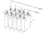
- the bus bar 1 includes a plus terminal 5 and a minus terminal 6 between the battery cells 2 in the assembled battery 3 configured by connecting a plurality of battery cells 2 in series. Used to connect.
- Each battery cell 2 is a lithium ion battery
- the positive terminal 5 is formed of aluminum or an aluminum alloy
- a male screw is formed on the outer peripheral surface.
- the negative terminal 6 is formed of copper or a copper alloy, and a male screw is formed on the outer peripheral surface.
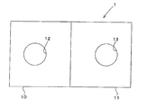
- the bus bar 1 is formed in a rectangular plate shape, and a positive electrode connection portion 10 is provided on one side of the middle with a middle position that bisects the long side as a boundary.
- a negative electrode connection portion 11 is provided on the other side.
- the dimensions of the bus bar 1 can be appropriately changed depending on the positions of the battery cells 2 and the amount of flowing current. For example, the length of the long side is 30 to 70 mm, the short side is 20 to 60 mm, and the thickness is 1 to 2 mm.
- the positive electrode connection portion 10 and the negative electrode connection portion 11 of the bus bar 1 are formed of different metals.
- the positive electrode connection part 10 is formed using the same metal as the plus terminal 5 of the battery cell 2, that is, aluminum or an aluminum alloy.
- the negative electrode connection portion 11 is formed using the same metal as the negative terminal 6, that is, copper or a copper alloy.
- the boundary between the positive electrode connection part 10 and the negative electrode connection part 11 in the bus bar 1 is deformed under a very high pressure (for example, about 1000 MPa) between the metal (Al) of the positive electrode connection part 10 and the metal (Cu) of the negative electrode connection part 11.
- a very high pressure for example, about 1000 MPa
- the positive electrode connection portion 10 is provided with a connection hole 12 into which the positive terminal 5 of the battery cell 2 is inserted at a substantially central portion in the short side direction, and the negative electrode connection portion 11 has the connection hole 12 of the battery cell 2.
- a connection hole 13 into which the minus terminal 6 is inserted is provided at a substantially central portion in the short side direction.
- the plus terminal 5 and the positive electrode connection portion 10 are connected by screwing a nut 15 into the penetrated plus terminal 5. Is done.
- a nut 15 is screwed into the minus terminal 6 to connect the minus terminal 6 and the negative electrode connection portion 11.
- the positive terminal 5 and the positive electrode connection portion 10 may be welded and the negative terminal 6 and the negative electrode connection portion 11 may be welded, instead of the coupling in which the nut 15 is screwed. That is, you may weld the dissimilar metal part of a bus bar directly to each same kind terminal.
- extrusion processing is performed under an ultrahigh hydrostatic pressure.
- the extrusion apparatus 20 used for this processing includes a die 21 having a single opening corresponding to the long-side cross-sectional shape (planar shape) of the bus bar 1 to be obtained, and isotropic pressure of ultrahigh pressure (about 1000 MPa). Extrusion under the environment is possible.
- a positive electrode base material 10 ⁇ / b> A (metal base material) made of the same metal (aluminum or aluminum alloy) as the positive terminal 5 of the battery cell 2 and the same metal ( A negative electrode base material 11A (metal base material) made of copper or a copper alloy is prepared.
- the positive electrode base material 10 ⁇ / b> A and the negative electrode base material 11 ⁇ / b> A may be formed as a round bar-shaped billet (face-to-face base material), for example, by sticking together strips along the longitudinal direction.
- this billet is loaded into the extrusion device 20 so that the positive electrode base material 10A and the negative electrode base material 11A are extruded in parallel with each other.
- the extrusion device 20 is operated in an ultrahigh-pressure isotropic pressure environment to perform an extrusion process or a drawing operation, and the positive electrode base material 10A and the negative electrode base material 11A are metal-bonded and integrated.
- the formed body 1A is formed.
- the opening area of the die 21 (die) of the extrusion device 20 is smaller than the cross-sectional area of the billet, when the die 21 is passed, the billet is subjected to overall circumferential compression and plastically deformed.
- the mating surfaces of the two base materials 10A and 11A form a bonding interface (metallic bonding portion) between the positive electrode connecting portion 10 and the negative electrode connecting portion 11 after exiting the die 21.
- the molded body 1A thus obtained is cut out at a predetermined interval in the extrusion direction. After cutting out, the connection hole 12 is provided in the positive electrode connection portion 10 and the connection hole 13 is provided in the negative electrode connection portion 11 to complete the bus bar 1. Surface polishing or surface treatment may be performed as necessary.
- the positive electrode connection portion 10 made of the same metal as the positive terminal 5 of the battery cell 2 and the negative electrode connection portion 11 made of the same metal as the negative terminal 6 of the battery cell 2 are integrally formed by metal connection. It is the structure which was made. For this reason, even in any part of this bus bar 1 (the connecting part with the battery terminal and the coupling surface between the positive electrode connecting part 10 and the negative electrode connecting part 11), electric corrosion does not occur and the electric resistance can be suppressed. In addition, the mechanical strength is excellent.
- [Second Embodiment] 4A and 4B show a second embodiment of the bus bar 1 according to the present invention.
- a stepped portion 25 having a bent shape in a side view is formed at a portion where a coupling interface (metallic coupling portion) between the positive electrode connecting portion 10 and the negative electrode connecting portion 11 is generated, and positive electrode connection is made.
- a difference in height is generated between the portion 10 and the negative electrode connecting portion 11.
- the size of the height difference between the positive electrode connecting portion 10 and the negative electrode connecting portion 11 in the step portion 25 is not limited.
- the stepped portion 25 is not limited to be formed so as to coincide with the bonding interface between the positive electrode connecting portion 10 and the negative electrode connecting portion 6, and is shifted to the positive electrode connecting portion 10 side or the negative electrode connecting portion 11 side. It can also be formed.
- the step portion 25 is not limited to be formed by crank bending, and may be formed so as to draw an S-shaped curve by a smooth curve.
- the opening shape of the die 21 may be a crank shape corresponding to the cross-sectional shape of the long side of the bus bar 1.
- Table 1 shows the characteristics of the bus bar of the first embodiment manufactured by extrusion or pultrusion under an ultra-high pressure isotropic pressure environment.
- a bus bar manufactured by friction stir welding (FSW) which is one of the conventional manufacturing methods
- laser welding which is one of the conventional manufacturing methods
- the bus bar manufactured by joining by the friction stir method has an electrical conductivity of 48.5% (one side stirring) and 49.0% (both stirring), and the conductivity value is bad.
- the bus bar manufactured by joining by laser welding has an electric conductivity of 60.4%, which is better than that of the friction stir method.
- the electrical conductivity is 66.1%, which is a very high value, and power transmission in the plurality of battery cells 2 can be performed with high efficiency without loss.
- the coupling interface (metallic coupling portion) between the positive electrode connecting portion 10 and the negative electrode connecting portion 11 is not limited to being arranged at the center of the long side of the bus bar 1, and the positive electrode connecting portion 10 side, or It is good also as arrangement
- the bus bar 1 according to the present invention is very suitable for connecting a lithium ion battery mounted on an automobile, but there is no problem even if it is used for connecting a lithium ion battery (battery) in other applications.
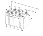
- the bus bar 101 includes a positive terminal 105 and a negative terminal 106 between the battery cells 102 in the assembled battery 103 configured by connecting a plurality of battery cells 102 in series. Used to connect.
- Each battery cell 102 is a lithium ion battery
- the positive terminal 105 is made of aluminum or an aluminum alloy
- a male screw is formed on the outer peripheral surface.
- the negative terminal 106 is formed of copper or a copper alloy, and a male screw is formed on the outer peripheral surface.
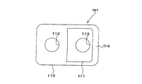
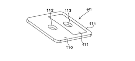
- the bus bar 101 is formed in a rectangular plate shape, and a positive electrode connection portion 110 is provided on one side of the middle with a middle position that bisects the long side.
- a negative electrode connecting portion 111 is provided on the other side.
- the positive electrode connection portion 110 is provided with a frame portion 114 so as to protrude toward the negative electrode connection portion 111, and the negative electrode connection portion 111 is fitted inside the frame portion 114. That is, the entire circumference of the outer periphery of the negative electrode connection 1 part 11 is surrounded by the positive electrode connection part 110.
- the dimensions of the bus bar 101 can be appropriately changed depending on the positions of the battery cells 102 and the amount of current flowing, and are, for example, a long side of 30 to 70 mm, a short side of 20 to 60 mm, and a thickness of 1 to 2 mm.
- the positive electrode connecting portion 110 and the negative electrode connecting portion 111 of the bus bar 101 are formed of different metals.
- the positive electrode connection part 110 is formed of the same metal as that of the plus terminal 105 of the battery cell 102, that is, aluminum or an aluminum alloy.
- the negative electrode connecting portion 111 is formed of the same metal as the negative terminal 106, that is, copper or a copper alloy.
- the positive electrode connecting portion 110 and the negative electrode connecting portion 111 are integrally coupled by a metallic bond between the joint surfaces along the inner periphery of the frame 114.
- This joining surface (boundary surface) is formed by applying deformation to the metal (Al) of the positive electrode connecting portion 110 and the metal (Cu) of the negative electrode connecting portion 111 under ultrahigh pressure (for example, about 1000 MPa).
- ultrahigh pressure for example, about 1000 MPa.
- a tightly bonded interface at the metal structure level is formed, and as a result, the electrical conductivity and mechanical bond strength are increased to “values suitable for practical use as a bus bar”.
- the aluminum or aluminum alloy forming the positive electrode connection portion 110 is softer than the copper or copper alloy forming the negative electrode connection portion 111. Due to the extrusion process under water pressure, the positive electrode connection part 110 is curved so as to swell toward the negative electrode connection part 111. Therefore, in the plan view of the present embodiment, the negative electrode connection portion 111 is shaped to be recessed toward the inside.
- the positive electrode connection portion 110 is provided with a connection hole 112 into which the positive terminal 105 of the battery cell 102 is inserted at the substantially central portion in the short side direction, and the negative electrode connection portion 111 has the connection hole 112 of the battery cell 102.
- a connection hole 113 into which the negative terminal 106 is inserted is provided at a substantially central portion in the short side direction.
- the plus terminal 105 and the positive electrode connection portion 110 are connected by screwing a nut 115 to the penetrated plus terminal 105. Is done.
- a nut 115 is screwed into the minus terminal 106 to connect the minus terminal 106 and the negative electrode connecting portion 111.
- the positive terminal 105 and the positive electrode connecting portion 110 may be welded and the negative terminal 106 and the negative electrode connecting portion 111 may be welded. That is, you may weld the dissimilar metal part of a bus bar directly to each same kind terminal.
- extrusion processing is performed under an ultrahigh hydrostatic pressure.
- the extrusion device 120 used for this processing is equipped with a single-opening die 121 (die) corresponding to the long-side cross-sectional shape (planar shape) of the bus bar 101 to be obtained, and has an ultrahigh pressure (about 1000 MPa). Extrusion under an isotropic pressure environment is possible.
- the manufacturing procedure of the bus bar 101 is as follows. First, a positive electrode base material 110A (metal base material) made of the same metal (aluminum or aluminum alloy) as the positive terminal 105 of the battery cell 102 and the same metal ( A negative electrode base material 111A (metal base material) made of copper or a copper alloy is prepared in a strip shape. Next, the strip-shaped positive electrode base material 110A and the negative electrode base material 111A are bonded together in the longitudinal direction, and the outside of the bonded members is wound around the plate-shaped positive electrode base material 110A, What is necessary is just to prepare the billet (facing material) which becomes a round bar shape as a whole. In addition, it is good also as a billet by inserting the member after bonding the base material 110A for positive electrodes and the base material 111A for negative electrodes in the base material 110A for positive electrodes of a hollow pipe shape.
- this billet is loaded into the extrusion device 120 so that the positive electrode base material 110A and the negative electrode base material 111A are extruded in parallel with each other.
- the extrusion device 120 is operated in an ultra-high pressure isotropic pressure environment to perform an extrusion process or a drawing operation, and the positive electrode base material 110A and the negative electrode base material 111A are metallically coupled and integrated.
- the formed body 1A is formed.
- the opening area of the die 121 of the extrusion device 120 is smaller than the cross-sectional area of the billet, by passing the die 121, the billet is subjected to overall compression and plastically deformed.
- the mating surfaces of the two base materials 110 ⁇ / b> A and 111 ⁇ / b> A form a bonding interface (metallic bonding portion) between the positive electrode connecting portion 110 and the negative electrode connecting portion 111 after exiting the die 121.
- the molded body 101A thus obtained is cut out at a predetermined interval in the extrusion direction. After cutting out, the connection hole 112 is provided in the positive electrode connection part 110 and the connection hole 113 is provided in the negative electrode connection part 111 to complete the bus bar 101. Surface polishing or surface treatment may be performed as necessary.
- a positive electrode connection part 110 made of the same metal as the positive terminal 105 of the battery cell 102 and a negative electrode connection part 111 made of the same metal as the negative terminal 106 of the battery cell 102 are integrally formed. It is the structure which was made. For this reason, any portion of the bus bar 11 (the connecting portion with the battery terminal, and the coupling surface between the positive electrode connecting portion 110 and the negative electrode connecting portion 111) can suppress electric resistance without causing electrical corrosion. Moreover, it has excellent mechanical strength.
- [Fourth Embodiment] 8A to 8C show a fourth embodiment of the bus bar 101 according to the present invention.
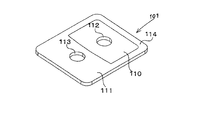
- the bus bar 101 of the fourth embodiment is also formed in a rectangular plate shape, and is provided with a positive electrode connection portion 110 (Al) on one side thereof with a middle position that bisects the long side as a boundary.
- a negative electrode connecting portion 111 (Cu) is provided on the side.
- the negative electrode connection portion 111 is provided with a frame portion 114 so as to protrude toward the positive electrode connection portion 110, and the positive electrode connection portion 110 is fitted inside the frame portion 114. . That is, the entire circumference of the outer periphery of the positive electrode connecting portion 110 is surrounded by the negative electrode connecting portion 111.
- the aluminum or aluminum alloy forming the positive electrode connecting portion 110 is softer than the copper or copper alloy forming the negative electrode connecting portion 111. Due to the extrusion process under water pressure, the positive electrode connection part 110 is curved so as to swell toward the negative electrode connection part 111. Therefore, in the plan view of the present embodiment, the positive electrode connection portion 110 has a shape that swells outward.
- the length and width of the frame portion 114 are not limited.
- the area ratio between the positive electrode connecting portion 110 and the negative electrode connecting portion 111 in a plan view can be changed as appropriate.
- the bus bar 101 according to the present invention is very suitable for connecting a lithium ion battery mounted on an automobile, but there is no problem even if it is used for connecting a lithium ion battery (battery) in other applications.
Landscapes
- Chemical & Material Sciences (AREA)
- Chemical Kinetics & Catalysis (AREA)
- Electrochemistry (AREA)
- General Chemical & Material Sciences (AREA)
- Inorganic Chemistry (AREA)
- Engineering & Computer Science (AREA)
- Manufacturing & Machinery (AREA)
- Connection Of Batteries Or Terminals (AREA)
Abstract
Description
一般に、異種の金属同士を接続したときに空気中の水分による電気腐食(電気化学的腐食)が起こることは周知である。従って、この電気腐食の進行に伴い、バスバーと端子との間が通電しなくなったりバスバー自体又は端子自体が損壊したりすることが起こり、最終的には、電気自動車を始動できないといった重大問題に至る。
好ましくは、前記正極接続部は、アルミニウム又はアルミニウム合金で形成され、前記負極接続部は、銅又は銅合金で形成されているとよい。
この製造方法を採用することで、正極接続部を形成する金属材と負極接続部を形成する金属材とが金属的結合して一体化し、バッテリのプラス端子とマイナス端子との間を好適に連結できるバスバーを製造することができる。
好ましくは、前記正極接続部は、アルミニウム又はアルミニウム合金で形成され、前記負極接続部は、銅又は銅合金で形成されているとよい。
[第1実施形態]
図1~図3は、本発明に係るバスバー1の第1実施形態を示している。
図1に示す使用例から分かるように、このバスバー1は、複数のバッテリセル2を直列接続することで構成される組電池3において、バッテリセル2相互間でプラス端子5とマイナス端子6とを接続するために用いる。
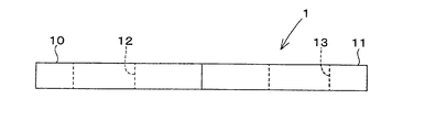
図2A及び2Bに示すように、バスバー1は、長方形の板状に形成されており、長辺側をほぼ二等分する中間位置を境として、その一方側に正極接続部10が設けられ、他方側に負極接続部11が設けられている。バスバー1の寸法は、バッテリセル2相互の位置や流れる電流量などにより適宜変更可能であるが、例えば、長辺30~70mm、短辺20~60mm、厚さ1~2mmである。
バスバー1における正極接続部10と負極接続部11との境界は、正極接続部10の金属(Al)と負極接続部11の金属(Cu)とを超高圧下(例えば1000MPa程度)で且つ変形を付与するようにして、互いが金属組織レベルで密着した結合界面を形成させ、その結果として導電性及び機械的結合強度を「バスバーとして実用に適する値」にまで高めた状態とされている。
図1に示したように、これら各接続孔12にプラス端子5を差し込んだ状態で、突き抜けたプラス端子5に対しナット15を螺合させることで、プラス端子5と正極接続部10とが連結される。同様に、接続孔13にマイナス端子6を差し込んだ上で、マイナス端子6に対しナット15を螺合させ、マイナス端子6と負極接続部11とを連結する。
図3に示す如く、このような構成のバスバー1を製造するには、超高圧静水圧下における押出加工を行う。この加工に用いる押出装置20は、得ようとするバスバー1の長辺側断面形状(平面形状)に対応した単一開口のダイ21を具備したもので、超高圧(1000MPa程度)の等方圧環境下での押出成形が可能である。
この状態で、押出装置20を超高圧の等方圧環境下にて作動させ、押出加工又は引抜作業を行い、正極用元材10Aと負極用元材11Aとが金属的結合して一体となった成形体1Aを成形する。
このようにして得られた成形体1Aを、押出方向で所定間隔をおいて切り出す。切り出し後において、正極接続部10に接続孔12を設け、負極接続部11に接続孔13を設けてバスバー1を完成させる。必要に応じて表面研磨や表面処理などを行ってもよい。
[第2実施形態]
図4A及び図4Bは、本発明に係るバスバー1の第2実施形態を示している。
更に、段差部25は、クランク折れによって形成することが限定されるものではなく、なめらかな曲線により、S字カーブを描くように形成してもよい。
その他の構成及び作用効果、製造方法は第1実施形態とほぼ同じであり、ここでの詳説は省略する。
比較対象としては、従来製造法の一つである摩擦攪拌法による接合(摩擦攪拌接合:Friction Stir Welding(FSW))を行って製造したバスバーと、従来製造法の一つであるレーザ溶接により接合を行って製造したバスバーとを例示する。

例えば、正極接続部10と負極接続部11との結合界面(金属的結合部)は、バスバー1における長辺側の中央に配置することが限定されるものではなく、正極接続部10側、又は負極接続部11側に偏らせた配置としてもよい。
図5~図7は、本発明に係るバスバー101の第3実施形態を示している。
図5に示す使用例から分かるように、このバスバー101は、複数のバッテリセル102を直列接続することで構成される組電池103において、バッテリセル102相互間でプラス端子105とマイナス端子106とを接続するために用いる。
図6A乃至6Cに示すように、バスバー101は、長方形の板状に形成されており、長辺側をほぼ二等分する中間位置を境として、その一方側に正極接続部110が設けられ、他方側に負極接続部111が設けられている。本実施形態の場合、正極接続部110は、負極接続部111側へ張り出すようにして枠部114が設けられており、この枠部114の枠内方に負極接続部111が嵌め込まれる。すなわち、正極接続部110により、負極接続1部11の外周部全周が取り囲まれる。
バスバー101の正極接続部110と負極接続部111とは、互いに異なる金属により形成されている。正極接続部110は、バッテリセル102のプラス端子105と同一金属、すなわちアルミニウム又はアルミニウム合金を素材として形成されている。また、負極接続部111は、マイナス端子106と同一金属、すなわち銅又は銅合金を素材として形成されている。
図5に示したように、これら各接続孔112にプラス端子105を差し込んだ状態で、突き抜けたプラス端子105に対しナット115を螺合させることで、プラス端子105と正極接続部110とが連結される。同様に、接続孔113にマイナス端子106を差し込んだ上で、マイナス端子106に対しナット115を螺合させ、マイナス端子106と負極接続部111とを連結する。
図7に示す如く、このような構成のバスバー101を製造するには、超高圧静水圧下における押出加工を行う。この加工に用いる押出装置120は、得ようとするバスバー101の長辺側断面形状(平面形状)に対応した単一開口のダイ121(ダイス)を具備したもので、超高圧(1000MPa程度)の等方圧環境下での押出成形が可能となる。
この状態で、押出装置120を超高圧の等方圧環境下にて作動させ、押出加工又は引抜作業を行い、正極用元材110Aと負極用元材111Aとが金属的結合して一体となった成形体1Aを成形する。
このようにして得られた成形体101Aを、押出方向で所定間隔をおいて切り出す。切り出し後において、正極接続部110に接続孔112を設け、負極接続部111に接続孔113を設けてバスバー101を完成させる。必要に応じて表面研磨や表面処理などを行ってもよい。
[第4実施形態]
図8A乃至8Cは、本発明に係るバスバー101の第4実施形態を示している。
ところが、本実施形態の場合、負極接続部111に、正極接続部110側へ張り出すようにして枠部114が設けられており、この枠部114の枠内方に正極接続部110が嵌め込まれる。すなわち、負極接続部111により、正極接続部110の外周部全周が取り囲まれる。
ところで、今回開示された実施形態はすべての点で例示であって制限的なものではない。本発明の範囲は上記した説明ではなくて特許請求の範囲によって示され、特許請求の範囲と均等の意味および範囲内でのすべての変更が含まれる。
また、本発明に係るバスバー101は、自動車搭載用のリチウムイオン電池を接続するに際し非常に好適であるが、他用途におけるリチウムイオン電池(バッテリ)の接続に用いても何ら問題はない。
本出願は、2010年3月29日出願の日本特許出願(特願2010-075915)、及び、2010年3月29日出願の日本特許出願(特願2010-075917)に基づくものであり、その内容はここに参照として取り込まれる。
1A 成形体
2 セル
3 組電池
5 正極端子
6 負極端子
10 正極接続部
10A 正極用元材
11 負極接続部
11A 負極用元材
12 接続孔
13 接続孔
15 ナット
20 押出装置
21 ダイ
25 段差部
101 バスバー
101A 成形体
102 セル
103 組電池
105 正極端子
106 負極端子
110 正極接続部
110A 正極用元材
111 負極接続部
111A 負極用元材
112 接続孔
113 接続孔
114 枠部
115 ナット
120 押出装置
121 ダイ
125 段差部
Claims (6)
- プラス端子とマイナス端子とが互いに異種金属で形成されたバッテリに対して用いる端子接続用のバスバーであって、
前記バッテリのプラス端子と同一金属で形成され且つプラス端子と接続可能とされた正極接続部と、前記バッテリのマイナス端子と同一金属で形成され且つマイナス端子と接続可能とされた負極接続部とを有し、
前記正極接続部と負極接続部とが金属的結合により一体化されていることを特徴とするバスバー。 - 前記正極接続部は、アルミニウム又はアルミニウム合金で形成され、
前記負極接続部は、銅又は銅合金で形成されていることを特徴とする請求項1に記載のバスバー。 - 前記正極接続部を形成する金属元材と負極接続部を形成する金属元材とが面で接する状態となっている対面元材を用意し、
高圧の静水圧環境下にて、前記対面元材をダイにより押出加工又は引抜加工することで、請求項1に記載されたバスバーを製造することを特徴とするバスバーの製造方法。 - プラス端子とマイナス端子とが互いに異種金属で形成されたバッテリに対して用いる端子接続用のバスバーであって、
前記バッテリのプラス端子と同一金属で形成され且つプラス端子と接続可能とされた正極接続部と、前記バッテリのマイナス端子と同一金属で形成され且つマイナス端子と接続可能とされた負極接続部とを有し、
平面視において、前記正極接続部の周りを負極接続部が取り囲む、又は負極接続部の周りを正極接続部が取り囲むように配備されていると共に、前記正極接続部と負極接続部とが金属的結合により一体的に結合されていることを特徴とするバスバー。 - 前記正極接続部は、アルミニウム又はアルミニウム合金で形成され、
前記負極接続部は、銅又は銅合金で形成されていることを特徴とする請求項4に記載のバスバー。 - 前記正極接続部を形成する金属元材の周りを負極接続部を形成する金属元材で取り囲んだ対面元材、又は負極接続部を形成する金属元材の周りを正極接続部を形成する金属元材で取り囲んだ対面元材を用意し、
高圧の静水圧環境下にて、前記対面元材をダイにより押出加工又は引抜加工することで、請求項4に記載されたバスバーを製造することを特徴とするバスバーの製造方法。
Priority Applications (5)
| Application Number | Priority Date | Filing Date | Title |
|---|---|---|---|
| KR1020147033978A KR101822229B1 (ko) | 2010-03-29 | 2011-03-24 | 버스 바 및 버스 바의 제조 방법 |
| KR1020127025706A KR20120138790A (ko) | 2010-03-29 | 2011-03-24 | 버스 바 및 버스 바의 제조 방법 |
| KR1020167009761A KR20160046920A (ko) | 2010-03-29 | 2011-03-24 | 버스 바 및 버스 바의 제조 방법 |
| US13/635,470 US8801444B2 (en) | 2010-03-29 | 2011-03-24 | Busbar and busbar manufacturing method |
| CN201180015121.8A CN102870254B (zh) | 2010-03-29 | 2011-03-24 | 汇流条、以及汇流条的制造方法 |
Applications Claiming Priority (4)
| Application Number | Priority Date | Filing Date | Title |
|---|---|---|---|
| JP2010075915A JP5483348B2 (ja) | 2010-03-29 | 2010-03-29 | バスバーの製造方法 |
| JP2010075917A JP5523165B2 (ja) | 2010-03-29 | 2010-03-29 | バスバーの製造方法 |
| JP2010-075915 | 2010-03-29 | ||
| JP2010-075917 | 2010-03-29 |
Publications (1)
| Publication Number | Publication Date |
|---|---|
| WO2011122453A1 true WO2011122453A1 (ja) | 2011-10-06 |
Family
ID=44712162
Family Applications (1)
| Application Number | Title | Priority Date | Filing Date |
|---|---|---|---|
| PCT/JP2011/057255 Ceased WO2011122453A1 (ja) | 2010-03-29 | 2011-03-24 | バスバー、及びバスバーの製造方法 |
Country Status (5)
| Country | Link |
|---|---|
| US (1) | US8801444B2 (ja) |
| KR (3) | KR20120138790A (ja) |
| CN (1) | CN102870254B (ja) |
| TW (1) | TWI478421B (ja) |
| WO (1) | WO2011122453A1 (ja) |
Cited By (5)
| Publication number | Priority date | Publication date | Assignee | Title |
|---|---|---|---|---|
| WO2012118014A1 (ja) * | 2011-02-28 | 2012-09-07 | 三洋電機株式会社 | バッテリシステム及びバッテリシステムを備える車両 |
| US20130309537A1 (en) * | 2012-05-21 | 2013-11-21 | Tyco Electronics Corporation | Boltless battery cell connection |
| EP2581966A4 (en) * | 2010-10-15 | 2014-01-15 | Kobe Steel Ltd | ELECTRICALLY CONDUCTIVE CONNECTING ELEMENT, METHOD FOR PRODUCING AN ELECTRICALLY CONDUCTIVE CONNECTING ELEMENT AND BATTERY WITH THE ELECTRICALLY CONDUCTIVE CONNECTING ELEMENT AS ELECTRODE |
| US20150214535A1 (en) * | 2014-01-28 | 2015-07-30 | Samsung Sdi Co., Ltd. | Secondary battery and secondary battery module |
| JP2020113524A (ja) * | 2019-01-15 | 2020-07-27 | Smk株式会社 | バスバーおよびバスバーの製造方法 |
Families Citing this family (41)
| Publication number | Priority date | Publication date | Assignee | Title |
|---|---|---|---|---|
| US8628875B2 (en) | 2010-04-16 | 2014-01-14 | Samsung Sdi Co., Ltd. | Battery module with multi-level connector |
| US9350007B2 (en) | 2011-01-27 | 2016-05-24 | Neomax Materials Co., Ltd. | Connection plate for battery terminals and method for manufacturing connection plate for battery terminals |
| DE102012208352A1 (de) * | 2012-05-18 | 2013-11-21 | Robert Bosch Gmbh | Verfahren zum Verbinden zweier aus ungleichen Materialien bestehenden Batteriepolen zweier Batteriezellen sowie Batterieeinheit |
| US9252550B2 (en) * | 2012-12-28 | 2016-02-02 | Hitachi Metals, Ltd. | Electrode terminal connector producing method |
| JP2014130740A (ja) * | 2012-12-28 | 2014-07-10 | Hitachi Metals Ltd | 電極端子接続体の製造方法 |
| EP2819217A1 (de) * | 2013-06-28 | 2014-12-31 | MAGNA STEYR Battery Systems GmbH & Co OG | Batteriesystem mit einem Zellverbinder und Verfahren zur Herstellung |
| EP2937916B1 (en) * | 2013-07-05 | 2020-05-06 | LG Chem, Ltd. | Battery module including connection members comprised of dissimilar metals |
| US9831482B2 (en) * | 2013-09-06 | 2017-11-28 | Johnson Controls Technology Company | Battery module lid system and method |
| US9722229B2 (en) | 2013-09-20 | 2017-08-01 | Ford Global Technologies, Llc | Electric vehicle battery attachment assembly and method |
| US9385356B2 (en) | 2014-04-30 | 2016-07-05 | Ford Global Technologies, Llc. | Terminal holder for electric vehicle battery assembly |
| DE102014210327A1 (de) * | 2014-06-02 | 2015-12-03 | Robert Bosch Gmbh | Elektrischer Zellverbinder für ein Batteriemodul |
| JP6380043B2 (ja) | 2014-11-21 | 2018-08-29 | 株式会社オートネットワーク技術研究所 | 蓄電モジュール |
| US9620764B2 (en) | 2015-01-05 | 2017-04-11 | Johnson Controls Technology Company | Battery module cooling fins and footings system and method |
| KR102316343B1 (ko) * | 2015-02-24 | 2021-10-21 | 삼성에스디아이 주식회사 | 이차 전지 및 그 모듈 |
| US10128486B2 (en) | 2015-03-13 | 2018-11-13 | Purdue Research Foundation | Current interrupt devices, methods thereof, and battery assemblies manufactured therewith |
| KR101623717B1 (ko) | 2015-08-21 | 2016-05-24 | 대산전자(주) | 전기 연결 수단의 제조 방법 |
| DE102016202873A1 (de) * | 2016-02-24 | 2017-08-24 | Bayerische Motoren Werke Aktiengesellschaft | Verfahren zur Herstellung eines elektrischen Verbindungselements und Verbindungselement für Batteriezellen |
| CN106025162B (zh) * | 2016-06-30 | 2019-11-08 | 上海捷新动力电池系统有限公司 | 一种软包电池模块连接结构 |
| US10787084B2 (en) * | 2017-03-17 | 2020-09-29 | Ford Global Technologies, Llc | Busbar with dissimilar materials |
| CN112743749A (zh) | 2017-04-04 | 2021-05-04 | 大山电子株式会社 | 汇流条的制造方法以及通过该制造方法而制造的汇流条 |
| KR102023638B1 (ko) | 2017-06-21 | 2019-09-20 | 대산전자(주) | 버스바의 제조방법 및 이를 통해 제조된 버스바 |
| KR102090619B1 (ko) | 2017-04-04 | 2020-03-19 | 대산전자(주) | 버스바의 제조방법 및 이를 통해 제조된 버스바 |
| WO2018186684A1 (ko) | 2017-04-04 | 2018-10-11 | 대산전자 주식회사 | 버스바의 제조방법 및 이를 통해 제조된 버스바 |
| DE102017129529A1 (de) * | 2017-12-12 | 2019-06-13 | Elringklinger Ag | Elektrisch leitfähige Verbindung und Verfahren zu deren Herstellung |
| CN108390005B (zh) * | 2018-02-01 | 2020-09-01 | 超威电源集团有限公司 | 一种铅酸蓄电池用高导电汇流排结构 |
| KR102383415B1 (ko) | 2018-03-20 | 2022-04-06 | 삼성에스디아이 주식회사 | 배터리 팩 |
| CN208209473U (zh) * | 2018-04-27 | 2018-12-07 | 施耐德电器工业公司 | 母线槽壳体 |
| KR102101451B1 (ko) * | 2018-05-10 | 2020-04-16 | 주식회사 경신 | 면대면 접합 버스바 |
| US10916492B2 (en) * | 2018-05-11 | 2021-02-09 | Advanced Semiconductor Engineering, Inc. | Semiconductor substrate and method of manufacturing the same |
| DE102018208340B4 (de) * | 2018-05-28 | 2025-05-08 | Bayerische Motoren Werke Aktiengesellschaft | Zellkontaktieranordnung für ein Energiespeichermodul und Verfahren zum Kontaktieren von Energiespeicherzellen eines Energiespeichermoduls |
| KR102127159B1 (ko) * | 2018-08-09 | 2020-06-26 | 주식회사 유라코퍼레이션 | 배터리 연결용 플레이트와 그 제조방법 및 이를 포함하는 배터리 연결 모듈 |
| US12136746B2 (en) * | 2018-10-29 | 2024-11-05 | Sanyo Electric Co., Ltd. | Method for producing busbar, busbar, and battery module |
| KR102034011B1 (ko) * | 2018-12-26 | 2019-10-18 | 에이에프더블류 주식회사 | 부스바 제조방법 |
| USD928088S1 (en) * | 2019-02-27 | 2021-08-17 | A.F.W. Co., Ltd. | Bus bar for fuses |
| CN113519086B (zh) * | 2019-03-12 | 2024-05-10 | 日本汽车能源株式会社 | 母线以及使用母线的电池模块 |
| KR102034012B1 (ko) * | 2019-04-05 | 2019-10-18 | 에이에프더블류 주식회사 | 마찰 교반 용접을 이용한 부스바 제조방법 |
| KR102541537B1 (ko) * | 2019-06-25 | 2023-06-08 | 주식회사 엘지에너지솔루션 | 전지 모듈 및 이를 포함하는 전지팩 |
| KR102132953B1 (ko) | 2019-09-16 | 2020-07-13 | 대산전자(주) | 버스바의 제조방법 및 이를 통해 제조된 버스바 |
| KR102831411B1 (ko) * | 2019-10-28 | 2025-07-08 | 주식회사 엘지에너지솔루션 | 이종금속으로 이루어진 버스바 및 이의 제조 방법 |
| KR102344019B1 (ko) | 2019-12-23 | 2021-12-28 | 대산전자(주) | 퓨즈가 적용된 버스바 |
| US20220263177A1 (en) * | 2020-11-17 | 2022-08-18 | Atlis Motor Vehicles, Inc. | Systems and Methods of Battery Assembly with Interlocking Features |
Citations (5)
| Publication number | Priority date | Publication date | Assignee | Title |
|---|---|---|---|---|
| JPS5790224A (en) * | 1980-11-27 | 1982-06-04 | Hitachi Cable Ltd | Composite rigid trolley |
| JPH11195434A (ja) * | 1997-10-07 | 1999-07-21 | Matsushita Electric Ind Co Ltd | 非水電解質二次電池 |
| JP2002151045A (ja) * | 2000-11-10 | 2002-05-24 | Honda Motor Co Ltd | 電池モジュール用バスバーおよび電池モジュール |
| JP2002358945A (ja) * | 2000-11-15 | 2002-12-13 | Ngk Insulators Ltd | リチウム二次単電池の接続構造体 |
| JP2003163039A (ja) * | 2001-11-27 | 2003-06-06 | Yazaki Corp | バスバーの接続構造 |
Family Cites Families (7)
| Publication number | Priority date | Publication date | Assignee | Title |
|---|---|---|---|---|
| US2806215A (en) | 1953-11-04 | 1957-09-10 | Aircraft Marine Prod Inc | Aluminum ferrule-copper tongue terminal and method of making |
| CA2274483C (en) * | 1997-10-07 | 2006-01-31 | Matsushita Electric Industrial Co., Ltd. | Non-aqueous electrolyte secondary battery |
| US6844110B2 (en) * | 2000-05-24 | 2005-01-18 | Ngk Insulators, Ltd. | Lithium secondary cell and assembly thereof |
| JP4029585B2 (ja) | 2001-06-18 | 2008-01-09 | 日産自動車株式会社 | バスバーおよびバスバーを用いた電池 |
| WO2008101067A1 (en) * | 2007-02-16 | 2008-08-21 | World Properties, Inc. | Laminated bus bars and methods of manufacture thereof |
| US20100248029A1 (en) * | 2009-01-07 | 2010-09-30 | A123 Systems, Inc. | Methods of welding battery terminals |
| JP5570383B2 (ja) * | 2010-10-15 | 2014-08-13 | 株式会社神戸製鋼所 | 導電性連結部材、導電性連結部材の製造方法、及び導電性連結部材が電極とされたバッテリ |
-
2011
- 2011-03-24 KR KR1020127025706A patent/KR20120138790A/ko not_active Ceased
- 2011-03-24 US US13/635,470 patent/US8801444B2/en not_active Expired - Fee Related
- 2011-03-24 KR KR1020167009761A patent/KR20160046920A/ko not_active Ceased
- 2011-03-24 CN CN201180015121.8A patent/CN102870254B/zh not_active Expired - Fee Related
- 2011-03-24 KR KR1020147033978A patent/KR101822229B1/ko not_active Expired - Fee Related
- 2011-03-24 WO PCT/JP2011/057255 patent/WO2011122453A1/ja not_active Ceased
- 2011-03-29 TW TW100110786A patent/TWI478421B/zh not_active IP Right Cessation
Patent Citations (5)
| Publication number | Priority date | Publication date | Assignee | Title |
|---|---|---|---|---|
| JPS5790224A (en) * | 1980-11-27 | 1982-06-04 | Hitachi Cable Ltd | Composite rigid trolley |
| JPH11195434A (ja) * | 1997-10-07 | 1999-07-21 | Matsushita Electric Ind Co Ltd | 非水電解質二次電池 |
| JP2002151045A (ja) * | 2000-11-10 | 2002-05-24 | Honda Motor Co Ltd | 電池モジュール用バスバーおよび電池モジュール |
| JP2002358945A (ja) * | 2000-11-15 | 2002-12-13 | Ngk Insulators Ltd | リチウム二次単電池の接続構造体 |
| JP2003163039A (ja) * | 2001-11-27 | 2003-06-06 | Yazaki Corp | バスバーの接続構造 |
Cited By (12)
| Publication number | Priority date | Publication date | Assignee | Title |
|---|---|---|---|---|
| EP2581966A4 (en) * | 2010-10-15 | 2014-01-15 | Kobe Steel Ltd | ELECTRICALLY CONDUCTIVE CONNECTING ELEMENT, METHOD FOR PRODUCING AN ELECTRICALLY CONDUCTIVE CONNECTING ELEMENT AND BATTERY WITH THE ELECTRICALLY CONDUCTIVE CONNECTING ELEMENT AS ELECTRODE |
| US9136617B2 (en) | 2010-10-15 | 2015-09-15 | Kobe Steel, Ltd. | Battery connector formed of plural materials, and production method |
| KR101765379B1 (ko) | 2010-10-15 | 2017-08-07 | 가부시키가이샤 고베 세이코쇼 | 도전성 연결 부재의 제조 방법 |
| WO2012118014A1 (ja) * | 2011-02-28 | 2012-09-07 | 三洋電機株式会社 | バッテリシステム及びバッテリシステムを備える車両 |
| US20130309537A1 (en) * | 2012-05-21 | 2013-11-21 | Tyco Electronics Corporation | Boltless battery cell connection |
| CN104321905A (zh) * | 2012-05-21 | 2015-01-28 | 泰科电子公司 | 无螺栓电池单体连接 |
| US9105912B2 (en) * | 2012-05-21 | 2015-08-11 | Tyco Electronics Corporation | Boltless battery cell connection |
| CN104321905B (zh) * | 2012-05-21 | 2018-04-06 | 泰科电子公司 | 无螺栓电池单体连接 |
| EP2852992B1 (en) * | 2012-05-21 | 2018-09-05 | TE Connectivity Corporation | Boltless battery cell connection |
| US20150214535A1 (en) * | 2014-01-28 | 2015-07-30 | Samsung Sdi Co., Ltd. | Secondary battery and secondary battery module |
| US9525163B2 (en) * | 2014-01-28 | 2016-12-20 | Samsung Sdi Co., Ltd. | Secondary battery and secondary battery module |
| JP2020113524A (ja) * | 2019-01-15 | 2020-07-27 | Smk株式会社 | バスバーおよびバスバーの製造方法 |
Also Published As
| Publication number | Publication date |
|---|---|
| TWI478421B (zh) | 2015-03-21 |
| KR20140146232A (ko) | 2014-12-24 |
| US20130012079A1 (en) | 2013-01-10 |
| KR20120138790A (ko) | 2012-12-26 |
| TW201214843A (en) | 2012-04-01 |
| KR101822229B1 (ko) | 2018-01-25 |
| CN102870254A (zh) | 2013-01-09 |
| US8801444B2 (en) | 2014-08-12 |
| CN102870254B (zh) | 2014-12-31 |
| KR20160046920A (ko) | 2016-04-29 |
Similar Documents
| Publication | Publication Date | Title |
|---|---|---|
| WO2011122453A1 (ja) | バスバー、及びバスバーの製造方法 | |
| JP5483348B2 (ja) | バスバーの製造方法 | |
| JP5523165B2 (ja) | バスバーの製造方法 | |
| JP5570383B2 (ja) | 導電性連結部材、導電性連結部材の製造方法、及び導電性連結部材が電極とされたバッテリ | |
| JP5523164B2 (ja) | 電極端子、及び電極端子の製造方法 | |
| CN101170171B (zh) | 引线构件及其接合方法和非水电解质电存储装置 | |
| US9159505B2 (en) | Electric storage device | |
| JP6845188B2 (ja) | 端子付き電線及びその製造方法 | |
| JP7285865B2 (ja) | 端子部品、二次電池および端子部品の製造方法 | |
| KR102000372B1 (ko) | 전선 접속 구조체의 제조방법, 및 전선 접속 구조체 | |
| JP2023062844A (ja) | 端子部品、二次電池、および、端子部品の製造方法 | |
| JP2014049333A (ja) | 接続構造体の製造方法、接続構造体、コネクタ、ワイヤハーネス | |
| JP2014164949A (ja) | 電線接続構造体の製造方法 | |
| JP2014164948A (ja) | 電線接続構造体の製造方法 |
Legal Events
| Date | Code | Title | Description |
|---|---|---|---|
| WWE | Wipo information: entry into national phase |
Ref document number: 201180015121.8 Country of ref document: CN |
|
| 121 | Ep: the epo has been informed by wipo that ep was designated in this application |
Ref document number: 11762684 Country of ref document: EP Kind code of ref document: A1 |
|
| WWE | Wipo information: entry into national phase |
Ref document number: 13635470 Country of ref document: US |
|
| ENP | Entry into the national phase |
Ref document number: 20127025706 Country of ref document: KR Kind code of ref document: A |
|
| NENP | Non-entry into the national phase |
Ref country code: DE |
|
| 122 | Ep: pct application non-entry in european phase |
Ref document number: 11762684 Country of ref document: EP Kind code of ref document: A1 |