WO2011122359A1 - 高圧放電ランプ - Google Patents
高圧放電ランプ Download PDFInfo
- Publication number
- WO2011122359A1 WO2011122359A1 PCT/JP2011/056387 JP2011056387W WO2011122359A1 WO 2011122359 A1 WO2011122359 A1 WO 2011122359A1 JP 2011056387 W JP2011056387 W JP 2011056387W WO 2011122359 A1 WO2011122359 A1 WO 2011122359A1
- Authority
- WO
- WIPO (PCT)
- Prior art keywords
- coil
- discharge lamp
- light emitting
- sealing
- pressure discharge
- Prior art date
- Legal status (The legal status is an assumption and is not a legal conclusion. Google has not performed a legal analysis and makes no representation as to the accuracy of the status listed.)
- Ceased
Links
Images



Classifications
-
- H—ELECTRICITY
- H01—ELECTRIC ELEMENTS
- H01J—ELECTRIC DISCHARGE TUBES OR DISCHARGE LAMPS
- H01J61/00—Gas-discharge or vapour-discharge lamps
- H01J61/02—Details
- H01J61/54—Igniting arrangements, e.g. promoting ionisation for starting
- H01J61/547—Igniting arrangements, e.g. promoting ionisation for starting using an auxiliary electrode outside the vessel
-
- H—ELECTRICITY
- H01—ELECTRIC ELEMENTS
- H01J—ELECTRIC DISCHARGE TUBES OR DISCHARGE LAMPS
- H01J61/00—Gas-discharge or vapour-discharge lamps
- H01J61/84—Lamps with discharge constricted by high pressure
- H01J61/86—Lamps with discharge constricted by high pressure with discharge additionally constricted by close spacing of electrodes, e.g. for optical projection
Definitions
- the present invention relates to a high-pressure discharge lamp, and in particular, it is possible to easily perform dielectric breakdown between a pair of electrodes provided in a light-emitting portion by a trigger wire provided so as to extend in the vicinity of the light-emitting portion of the high-pressure discharge lamp.
- the present invention relates to a high-pressure discharge lamp that can be used.
- a high-pressure discharge lamp is required to apply a high pulse voltage at the time of starting in order to cause a dielectric breakdown between a pair of electrodes provided in a light emitting portion of the high-pressure discharge lamp. Therefore, it has been a conventional problem to easily start the high-pressure discharge lamp.
- a high pulse voltage is generated by arranging an igniter for generating a high pulse voltage in the high pressure discharge lamp, or arranging a starter such as a lighting tube in the high pressure discharge lamp. .
- the method of lighting by applying a high pulse voltage required appropriate insulation for wiring, sockets and the like.
- the starter is built in the high-pressure discharge lamp, the high-pressure discharge lamp itself becomes large, and the high-pressure discharge lamp cannot be reduced in size. For this reason, the structure which reduces the starting voltage of a high voltage
- Patent Document 1 in order to reduce the starting voltage of a high-pressure discharge lamp, two metal coils are wound around the outer periphery of a small-diameter cylindrical portion on both sides of the arc tube, and each metal coil is connected to the arc tube.
- a high-pressure discharge lamp is shown which extends to the opposite side of the electrode and is connected to have the same potential as the electrode on the opposite side.
- Patent Document 2 one is wound around the outer periphery of the sealing portion at one end of the arc tube, and the other is straddling the vicinity of the arc tube from the outer end of the sealing portion at the other end of the arc tube.
- a high-pressure discharge lamp is shown that includes a trigger wire connected to an extended external lead and having the same potential as the external lead.
- the distance between the spanning portion and the electrode is constant, so that the effect of reducing the starting voltage can be sufficiently expected. If repeated, the thermal expansion and contraction are repeated, so that the separation distance between the stretched portion and the electrode becomes wider than the original, and the effect of reducing the starting voltage cannot be sufficiently obtained.
- the object of the present invention is to obtain the effect of reducing the starting voltage over a long period of time by preventing the drooping of the spanning part extending near the light emitting part of the trigger wire in view of the above-mentioned problems of the prior art.
- An object of the present invention is to provide a high-pressure discharge lamp capable of performing
- the present invention employs the following means in order to solve the above problems.
- the first means includes a light emitting part in which a pair of electrodes are arranged to face each other, a sealing part provided continuously at both ends of the light emitting part, and held by the respective sealing parts.
- An external lead extending from the outer end of each sealing part, and a trigger wire provided in the vicinity of the light emitting part, the trigger wire from the vicinity of the boundary between the light emitting part and one sealing part
- the high-pressure discharge lamp having a linear stretch portion that extends in the vicinity of the light emitting portion and is fixed to the external lead, a second coil portion is formed in the other sealing portion, and the stretch portion is The wire to be formed is sandwiched between the second coil portion and the other sealing portion.
- the second means is the high-pressure discharge lamp according to the first means, wherein the second coil part is a separate member from the first coil part.
- the third means is the first means or the second means, wherein the span portion is the winding portion other than the winding portion located closest to the light emitting portion among the second coil portions and the other winding portion.
- a high-pressure discharge lamp characterized by being sandwiched between a sealing portion.
- the fourth means is the first means or the second means, wherein the first coil part and / or the second coil part are arranged so that the coil pitch is close in the vicinity of the light emitting part. And a sparse part disposed so that a coil pitch is sparser than the dense part toward an outer end side of the sealing part provided with the dense part.
- This is a high pressure discharge lamp.
- a fifth means is the first means or the second means, wherein the high-pressure discharge lamp comprises a metal foil embedded in each of the sealing portions, and one end of each of the metal foils is the pair of electrodes.
- the first coil portion and / or the second coil portion is a high pressure discharge lamp characterized in that a coil pitch around the metal foil is sparse compared to a coil pitch near the light emitting portion. is there.
- the second coil portion prevents the span from hanging down. It is possible to make the distance from the electrode arranged in the long-term constant. As a result, the effect of reducing the starting voltage of the high-pressure discharge lamp over a long period can be obtained.
- the trigger wire can be easily attached to the high pressure discharge lamp.
- the extending portion can be disposed at a location appropriately separated from the light emitting portion, it is possible to prevent the light emitting portion from being damaged or devitrified.
- the temperature of a light emission part can be raised easily.
- the excessive raise of metal foil temperature can be prevented.
- FIG. 1 is an explanatory front sectional view showing a configuration of a high-pressure discharge lamp according to the present embodiment.
- the high-pressure discharge lamp 1 includes a spherical light emitting portion 2 made of quartz glass, and a pair of sealing portions 3 and 4 respectively connected to both ends of the light emitting portion 2.
- mercury is sealed in an amount of 0.15 mg / mm 3 or more so that the mercury vapor pressure when it is lit in the steady mode is 150 atm or more, and a pair of the ends face each other.
- Electrodes 5 and 6 are arranged.
- the electrodes 5 and 6 include spherical heads 51 and 61 with protrusions, shafts 53 and 63 connected to the rear of the heads 51 and 61, and the shafts 53 and 63.
- Coil portions 52 and 62 provided in regions following the head portions 51 and 61 are provided, and these are integrally formed of tungsten.
- the sealing portions 3 and 4 are hermetically sealed by embedding metal foils 7 and 8 made of molybdenum, respectively.
- Each metal foil 7, 8 has one end connected to the end of each shaft 53, 63 and the other end connected to external leads 9, 10.
- the respective external leads 9 and 10 extend outward from the respective sealing portions 3 and 4.
- Mercury enclosed in the light emitting unit 2 is for obtaining a necessary visible light wavelength, for example, radiation having a wavelength of 360 to 780 nm, and is contained in an amount of 0.15 mg / mm 3 or more. Although it depends on the temperature condition, it is for forming an extremely high vapor pressure of 150 atm or more at the time of lighting. Further, by enclosing a larger amount of mercury, a discharge lamp having a high mercury vapor pressure such as a mercury vapor pressure of 200 atmospheric pressure or higher and 300 atmospheric pressure or higher can be made when the lamp is turned on. Can be realized.
- the rare gas is, for example, argon gas and is sealed at about 10 to 26 kPa at a static pressure.
- the reason for enclosing such a rare gas is to improve the lighting startability.
- halogen, iodine, bromine, chlorine, etc. are enclosed in the form of a compound with mercury or other metal, and the amount of halogen enclosed is selected from the range of 10 ⁇ 6 to 10 ⁇ 2 ⁇ mol / mm 3 . Its function is also for the purpose of prolonging the life (preventing blackening) using the halogen cycle, but in the case of an extremely small and high internal pressure such as the high-pressure discharge lamp of the present invention, to prevent devitrification of the light emitting part. But there is.
- the trigger wire 11 includes a first coil part 111 wound around one sealing part 3 and a spanning part 112 connected to the first coil part 111.
- the first coil part 111 is wound from the vicinity of the boundary between the light emitting part 2 and the one sealing part 3 toward the outer end of the one sealing part 3.
- the spanning portion 112 integrally connected to the first coil portion 111 extends near the light emitting portion 2 toward the outer end of the other sealing portion 4 and is connected to the other external lead 10.
- the first coil portion 111 wound around one sealing portion 3 has the same potential as the other external lead 10 extending outward from the other sealing portion 4.
- a second coil portion 113 that is a separate member physically independent of the first coil portion 111 is wound around the other sealing portion 4.
- a spanning portion 112 connected to the first coil portion 111 extends in the vicinity of the light emitting portion 2 and is passed through the inside of the second coil portion 113, and the glass of the second coil portion 113 and the other sealing portion 4. Is sandwiched between.
- the material of the trigger wire 11 for example, an alloy of Fe and Cr is used, and the diameter of the wire is, for example, 0.3 mm.
- FIG. 2 is an enlarged front sectional view showing a part of the configuration in the vicinity of the light emitting part 2 and the other sealing part 4 of the high-pressure discharge lamp 1 according to the present embodiment.
- the spanning portion 112 that extends in the vicinity of the light emitting portion 2 of the trigger wire 11 is the winding closest to the light emitting portion 2 among the plurality of winding portions constituting the second coil portion 113.
- the portion 113a for example, it is sandwiched between the other sealing portion 4 by the winding portions 113f to 113i.
- the spanning portion 112 is inserted into the inside of the winding portion 113f of the sixth turn counted from the light emitting portion 2 side among the plurality of winding portions 113a to 113i constituting the second coil portion 113. Has been.
- the winding portion 113a closest to the light emitting portion 2 of the second coil portion 113 is avoided as the winding portion for fixing the spanning portion 112 as described above.
- the spanning portion 112 may come into contact with the light emitting portion 2, thereby possibly damaging the light emitting portion 2.
- the spanning part 112 is too close to the light emitting part 2, the spanning part 112 itself becomes hot and abuts against the light emitting part 2, which may cause the light emitting part 2 to be devitrified.
- the reason for the devitrification is that when the spanning part 112 comes into contact with the light emitting part 2, the temperature of the contact part of the light emitting part 2 rises or dirt on the surface of the spanning part 112 is taken into the light emitting part 2. This is probably because the glass becomes cloudy and crystallizes.
- the winding portions other than the winding portion 113a closest to the light emitting portion 2 among the plurality of winding portions 113a to 113i constituting the second coil portion 113 for example, the winding portions 113f to 113i.
- the second coil portion 113 is wound around the boundary between the light emitting portion 2 and the other sealing portion 4.
- a dense portion 1131 having a small coil interval between the adjacent winding portions 113a to 113e and, for example, wound on the outer end (right side of the drawing in FIG. 1) side of the other sealing portion 4 from the dense portion 1131.
- a sparse portion 1132 having a large coil interval between the adjacent winding portions 113f to 113i.
- the dense portion 1131 has an interval between adjacent coils of 0.3 mm or less
- the sparse portion 1132 has an interval between adjacent coils of 0.5 mm or more, for example, 2.3 mm.
- the coil pitch of the dense portion 1131 which is a region near the light emitting portion 2 in the other sealing portion 4 is small, and the second sealing portion 4
- the coil pitch of the sparse part 1132 which is a region far from the light emitting part 2 is large.
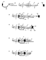
- FIG. 3 is a view showing a method for attaching a trigger wire in the high-pressure discharge lamp according to the present embodiment.
- the first coil portion 111 is connected to one sealing portion 3. Insert from the side to the vicinity of the boundary between one sealing portion 3 and the light emitting portion 2 and attach.
- the spanning portion 112 is extended along the light emitting portion 2 and the other sealing portion 4.
- the spanning part 112 is inserted outside the dense part 1131 of the second coil part 113 and inside the sparse part 1132 among the second coil parts 113. To be arranged.
- FIG. 3 (d) in the state of FIG. Insert it near the border and put it on.
- the distal end portion of the spanning portion 112 is fixed to the other external lead 10.
- FIG. 4 is a front sectional view showing the configuration of the high-pressure discharge lamp according to the present embodiment.
- the trigger wire 12 of the present embodiment includes the first coil portion 121 and the second coil portion 123 formed by a single trigger wire. Is different.
- the trigger wire 12 according to the present embodiment includes a first coil unit 121 disposed around one sealing unit 3, and the light emitting unit 2 following the first coil unit 121.
- a stretched portion 122 extending along the stretched portion 122, a second coil portion 123 wound around the other sealed portion 4 following the stretched portion 122, and a connecting portion 124 following the second coil portion 123.
- the trigger wire 12 has the same potential as that of the other external lead 10 when the connecting portion 124 is wound around the other external lead 10.
- the first coil unit 121 is disposed near the boundary between the light emitting unit 2 and the one sealing unit 3, and the first sealing unit 3 extends from the boundary between the light emitting unit 2 and the one sealing unit 3. Wrapped towards the outer end of the.
- the span portion 122 is provided between the one sealing portion 3 and the other sealing portion 4 so as to extend along the light emitting portion 2 in the vicinity of the light emitting portion 2.
- the second coil portion 123 is disposed in the vicinity of the boundary between the light emitting portion 2 and the other sealing portion 4, and extends from the boundary between the light emitting portion 2 and the other sealing portion 4 toward the outer end of the other sealing portion 4. Is wound.
- the connecting part 124 following the second coil part 123 extends outward from the second coil part 123 in the direction of the light emitting part 2 and is folded in a U-shape in the opposite direction in the vicinity of the light emitting part 2.
- 123 passes through the inside of 123, extends toward the outer end of the other sealing portion 4, and is wound and connected to the other external lead 10.
Landscapes
- Discharge Lamps And Accessories Thereof (AREA)
Abstract
トリガーワイヤの発光部付近を延伸する張渡部の垂下りを防止し、始動電圧を低減させる効果を長期的に保持する。 本発明は、一対の電極(5、6)が対向して配置された発光部(2)と、発光部(2)の両端に連接された封止部(3、4)と、封止部(3、4)に保持され各封止部(3、4)外端から伸び出した外部リード(9、10)と、発光部(2)の付近に設けられたトリガーワイヤ(11)とを備え、トリガーワイヤ(11)は、発光部(2)と一方の封止部(3)との境界付近から一方の封止部(3)の外端に向けて巻装されてなる第1のコイル部(111)と、第1のコイル部(111)から、他方の外部リード(10)に向って発光部(2)の付近を延伸すると共に外部リード(10)に固定された線状の張渡部(112)とを備える高圧放電ランプにおいて、他方の封止部(4)には、第2のコイル部(113)が形成され、張渡部(112)を形成するワイヤは、第2のコイル部(113)と他方の封止部(4)との間で挟持される。
Description
本発明は、高圧放電ランプに関し、特に、高圧放電ランプの発光部の付近を延伸するように設けられたトリガーワイヤによって、発光部内に設けられた一対の電極間における絶縁破壊を容易に行うことのできる高圧放電ランプに関する。
高圧放電ランプは、一般的に始動時に、高圧放電ランプの発光部内に設けられた一対の電極間の絶縁破壊を行うために、高いパルス電圧を印加することが必要とされている。そのため、高圧放電ランプを容易に始動させることは従来からの課題であった。従来においては、高いパルス電圧を発生させるイグナイタを高圧放電ランプに配設したり、点灯管などの始動器を高圧放電ランプに配設する等して、高いパルス電圧を発生させるようにしていた。
しかしながら、高パルス電圧を印加させて点灯する方法は、配線、ソケットなどに相応の絶縁性が必要であった。また、高圧放電ランプ内に始動器を内蔵することは、高圧放電ランプ自体が大きくなるため高圧放電ランプを小型化することができない。このため、高圧放電ランプの始動電圧を低減し、高いパルス電圧を必要としない構成が求められている。
しかしながら、高パルス電圧を印加させて点灯する方法は、配線、ソケットなどに相応の絶縁性が必要であった。また、高圧放電ランプ内に始動器を内蔵することは、高圧放電ランプ自体が大きくなるため高圧放電ランプを小型化することができない。このため、高圧放電ランプの始動電圧を低減し、高いパルス電圧を必要としない構成が求められている。
例えば、特許文献1には、高圧放電ランプの始動電圧を低減するために、2つの金属製コイルを発光管の両側の小径筒部の外周に巻装するとともに、各金属製コイルが、発光管の反対側に伸びて当該反対側の電極と同電位となるように接続した高圧放電ランプが示されている。
また、特許文献2には、一方を発光管の一端側の封止部の外周に巻装するとともに、他方を発光管の近傍を跨いで発光管の他端側の封止部の外端から伸び出た外部リードに接続して、該外部リードと同電位となるトリガーワイヤを備える高圧放電ランプが示されている。
また、特許文献2には、一方を発光管の一端側の封止部の外周に巻装するとともに、他方を発光管の近傍を跨いで発光管の他端側の封止部の外端から伸び出た外部リードに接続して、該外部リードと同電位となるトリガーワイヤを備える高圧放電ランプが示されている。
しかしながら、このような従来技術に係る高圧放電ランプは、短期的には始動電圧を低減させることはできるが、点灯及び消灯を長期に繰返し行うに従って、始動電圧を低減させる効果が次第に低下することが確認された。
これは、高圧放電ランプの点灯及び消灯を長期に繰り返し行った場合、封止部の外周に巻装されたコイル部が次第に緩むため、コイル部に繋がる張渡部が鉛直方向下方に垂下がり、張渡部と発光部内に配置された電極との離間距離が広がるためである。
つまり、高圧放電ランプの点灯及び消灯の回数が少ない初期においては、張渡部と電極との離間距離が一定であるために、始動電圧を低減させる効果は十分に期待できるが、点灯及び消灯を何度も繰り返し行うと、熱膨張と収縮が繰り返されるため、張渡部と電極との離間距離が当初よりも広くなり、始動電圧を低減させる効果を十分に得ることができないためと考えられる。
これは、高圧放電ランプの点灯及び消灯を長期に繰り返し行った場合、封止部の外周に巻装されたコイル部が次第に緩むため、コイル部に繋がる張渡部が鉛直方向下方に垂下がり、張渡部と発光部内に配置された電極との離間距離が広がるためである。
つまり、高圧放電ランプの点灯及び消灯の回数が少ない初期においては、張渡部と電極との離間距離が一定であるために、始動電圧を低減させる効果は十分に期待できるが、点灯及び消灯を何度も繰り返し行うと、熱膨張と収縮が繰り返されるため、張渡部と電極との離間距離が当初よりも広くなり、始動電圧を低減させる効果を十分に得ることができないためと考えられる。
本発明の目的は、上記の従来技術の問題点に鑑みて、トリガーワイヤの発光部付近を延伸する張渡部の垂下りを防止することにより、始動電圧を低減させる効果を長期に亘って得ることのできる高圧放電ランプを提供することにある。
本発明は、上記の課題を解決するために、次のような手段を採用した。
第1の手段は、内部に一対の電極が対向して配置された発光部と、該発光部の両端のそれぞれに連設された封止部と、前記それぞれの封止部に保持されると共にそれぞれの封止部の外端から伸び出した外部リードと、前記発光部の付近に設けられたトリガーワイヤとを備え、該トリガーワイヤは、前記発光部と一方の封止部との境界付近から該一方の封止部の外端に向けて巻装されてなる第1のコイル部と、該第1のコイル部から、他方の封止部の外端から伸び出した外部リードに向って前記発光部の付近を延伸すると共に該外部リードに固定された線状の張渡部とを備える高圧放電ランプにおいて、前記他方の封止部には、第2のコイル部が形成され、前記張渡部を形成するワイヤは、前記第2のコイル部と前記他方の封止部との間で挟持されていることを特徴とする高圧放電ランプである。
第2の手段は、第1の手段において、前記第2のコイル部は、前記第1のコイル部と別部材であることを特徴とする高圧放電ランプである。
第3の手段は、第1の手段又は第2の手段において、前記張渡部は、前記第2のコイル部のうちで最も発光部側に位置する巻回部以外の巻回部と前記他方の封止部との間で挟持されることを特徴とする高圧放電ランプである。
第4の手段は、第1の手段又は第2の手段において、前記第1のコイル部及び/又は前記第2のコイル部は、前記発光部の付近においてコイルピッチが密になるように配設された密部と、該密部が配設された封止部の外端側に向けてコイルピッチが前記密部より疎になるように配設された疎部とを有することを特徴とする高圧放電ランプである。
第5の手段は、第1の手段又は第2の手段において、前記高圧放電ランプは、前記それぞれの封止部に埋設された金属箔を備え、前記それぞれの金属箔の一端が前記一対の電極のそれぞれの端部に接続されると共に、前記それぞれの金属箔の他端がそれぞれの外部リードに接続され、
前記第1のコイル部及び/又は前記第2のコイル部は、前記金属箔の周囲におけるコイルピッチが、前記発光部の付近におけるコイルピッチに比べて疎であることを特徴とする高圧放電ランプである。
第1の手段は、内部に一対の電極が対向して配置された発光部と、該発光部の両端のそれぞれに連設された封止部と、前記それぞれの封止部に保持されると共にそれぞれの封止部の外端から伸び出した外部リードと、前記発光部の付近に設けられたトリガーワイヤとを備え、該トリガーワイヤは、前記発光部と一方の封止部との境界付近から該一方の封止部の外端に向けて巻装されてなる第1のコイル部と、該第1のコイル部から、他方の封止部の外端から伸び出した外部リードに向って前記発光部の付近を延伸すると共に該外部リードに固定された線状の張渡部とを備える高圧放電ランプにおいて、前記他方の封止部には、第2のコイル部が形成され、前記張渡部を形成するワイヤは、前記第2のコイル部と前記他方の封止部との間で挟持されていることを特徴とする高圧放電ランプである。
第2の手段は、第1の手段において、前記第2のコイル部は、前記第1のコイル部と別部材であることを特徴とする高圧放電ランプである。
第3の手段は、第1の手段又は第2の手段において、前記張渡部は、前記第2のコイル部のうちで最も発光部側に位置する巻回部以外の巻回部と前記他方の封止部との間で挟持されることを特徴とする高圧放電ランプである。
第4の手段は、第1の手段又は第2の手段において、前記第1のコイル部及び/又は前記第2のコイル部は、前記発光部の付近においてコイルピッチが密になるように配設された密部と、該密部が配設された封止部の外端側に向けてコイルピッチが前記密部より疎になるように配設された疎部とを有することを特徴とする高圧放電ランプである。
第5の手段は、第1の手段又は第2の手段において、前記高圧放電ランプは、前記それぞれの封止部に埋設された金属箔を備え、前記それぞれの金属箔の一端が前記一対の電極のそれぞれの端部に接続されると共に、前記それぞれの金属箔の他端がそれぞれの外部リードに接続され、
前記第1のコイル部及び/又は前記第2のコイル部は、前記金属箔の周囲におけるコイルピッチが、前記発光部の付近におけるコイルピッチに比べて疎であることを特徴とする高圧放電ランプである。
請求項1に記載の発明によれば、高圧放電ランプの点灯と消灯を長期にわたり繰り返しても、張渡部の垂れ下がりが第2のコイル部によって防止されることから、トリガーワイヤの張渡部と発光部内に配置された電極との離間距離を長期的に一定にすることができる。その結果、長期にわたり高圧放電ランプの始動電圧を低減する効果を得ることができる。
請求項2に記載の発明によれば、高圧放電ランプに対してトリガーワイヤを容易に取付けることができる。
請求項3に記載の発明によれば、張渡部を発光部から適当に離れた箇所に配設することができるため、発光部における損傷又は失透の発生を防止することができる。
請求項4に記載の発明によれば、発光部の温度を容易に上昇させることができる。請求項5に記載の発明によれば、金属箔温度の過剰な上昇を防止することができる。
請求項2に記載の発明によれば、高圧放電ランプに対してトリガーワイヤを容易に取付けることができる。
請求項3に記載の発明によれば、張渡部を発光部から適当に離れた箇所に配設することができるため、発光部における損傷又は失透の発生を防止することができる。
請求項4に記載の発明によれば、発光部の温度を容易に上昇させることができる。請求項5に記載の発明によれば、金属箔温度の過剰な上昇を防止することができる。
本発明の第1の実施形態を図1を用いて説明する。
図1は、本実施形態に係る高圧放電ランプの構成を示す説明用正面断面図である。
同図に示すように、この高圧放電ランプ1は、石英ガラスからなる球状の発光部2と、発光部2の両端にそれぞれ連設された一対の封止部3、4とで構成される。発光部2内には、定常モードで点灯したときの水銀蒸気圧が150気圧以上となるように、水銀が0.15mg/mm3 以上封入されていると共に、それぞれの先端が向き合うように一対の電極5、6が配置されている。
図1は、本実施形態に係る高圧放電ランプの構成を示す説明用正面断面図である。
同図に示すように、この高圧放電ランプ1は、石英ガラスからなる球状の発光部2と、発光部2の両端にそれぞれ連設された一対の封止部3、4とで構成される。発光部2内には、定常モードで点灯したときの水銀蒸気圧が150気圧以上となるように、水銀が0.15mg/mm3 以上封入されていると共に、それぞれの先端が向き合うように一対の電極5、6が配置されている。
電極5、6は、同図に示すように、突起が形成された球状の頭部51、61と、頭部51、61の後方に連なる軸部53、63と、この軸部53、63の頭部51、61に続く領域に設けられたコイル部52、62とを備え、これらがタングステンによって一体的に構成されている。それぞれの封止部3、4には、それぞれモリブデンからなる金属箔7、8が埋設されることで気密に封止されている。それぞれの金属箔7、8は、それぞれの一端にそれぞれの軸部53、63の端部が接続されると共に、それぞれの他端に外部リード9、10が接続されている。それぞれの外部リード9、10は、それぞれの封止部3、4の外方へと伸び出ている。
発光部2内に封入される水銀は、必要な可視光波長、例えば、波長360~780nmという放射光を得るためのものであり、0.15mg/mm3 以上封入されており、この封入量は、温度条件によっても異なるが、点灯時150気圧以上という極めて高い蒸気圧を形成するためのものである。また、水銀をより多く封入することで点灯時の水銀蒸気圧が200気圧以上、300気圧以上という高い水銀蒸気圧の放電ランプを作ることができ、水銀蒸気圧が高くなるほどプロジェクタ装置に適した光源を実現することができる。
希ガスは、例えば、アルゴンガスであり、静圧で約10~26kPa封入される。このような希ガスを封入するのは、点灯始動性を改善するためである。また、ハロゲンは、沃素、臭素、塩素などが、水銀その他の金属との化合物の形態で封入され、ハロゲンの封入量は、10-6~10-2μmol/mm3 の範囲から選択される。その機能は、ハロゲンサイクルを利用した長寿命化(黒化防止)のためでもあるが、本発明の高圧放電ランプのように極めて小型で高い内圧を有するものの場合、発光部の失透防止のためでもある。
この高圧放電ランプ1は、それぞれの外部リード9、10及び金属箔7、8を介して一対の電極5、6間に電圧が印加されることにより、電極5、6間で絶縁破壊が生じてプラズマが形成される。プラズマから放射される光のスペクトルは、紫外域から赤外域の広範囲に亘る。
トリガーワイヤ11は、図1に示すように、一方の封止部3に巻装された第1のコイル部111と、第1のコイル部111に繋がる張渡部112とを有する。第1のコイル部111は、発光部2と一方の封止部3との境界付近から一方の封止部3の外端に向けて巻装されている。第1のコイル部111に一体的に繋がる張渡部112は、発光部2付近を他方の封止部4の外端に向けて延伸し、他方の外部リード10に接続される。一方の封止部3に巻装された第1のコイル部111は、他方の封止部4の外方に伸び出た他方の外部リード10と同電位である。更に、他方の封止部4には、第1のコイル部111と物理的に独立した別部材である第2のコイル部113が巻装されている。第1のコイル部111に繋がる張渡部112が、発光部2付近を延伸すると共に、第2のコイル部113の内方に通され、第2のコイル部113と他方の封止部4のガラスとの間で挟持される。
トリガーワイヤ11の材質としては、例えば、FeとCrの合金が用いられ、その線径は、例えば、直径0.3mmである。
トリガーワイヤ11の材質としては、例えば、FeとCrの合金が用いられ、その線径は、例えば、直径0.3mmである。
次に、本発明の第2の実施形態を図2を用いて説明する。
図2は、本実施形態に係る高圧放電ランプ1の発光部2と他方の封止部4付近の構成の一部を拡大して示した正面断面図である。
同図に示すように、トリガーワイヤ11の、発光部2付近を延伸する張渡部112は、第2のコイル部113を構成する複数の巻回部のうち、発光部2に最も近接する巻回部113a以外の、例えば、巻回部113f~113iによって他方の封止部4との間で挟持されている。具体的には、張渡部112が第2のコイル部113を構成する複数の巻回部113a~113iのうちで、発光部2側から数えて6周目の巻回部113fの内方に挿入されている。
図2は、本実施形態に係る高圧放電ランプ1の発光部2と他方の封止部4付近の構成の一部を拡大して示した正面断面図である。
同図に示すように、トリガーワイヤ11の、発光部2付近を延伸する張渡部112は、第2のコイル部113を構成する複数の巻回部のうち、発光部2に最も近接する巻回部113a以外の、例えば、巻回部113f~113iによって他方の封止部4との間で挟持されている。具体的には、張渡部112が第2のコイル部113を構成する複数の巻回部113a~113iのうちで、発光部2側から数えて6周目の巻回部113fの内方に挿入されている。
このように張渡部112を固定するための巻回部として、第2のコイル部113の発光部2に最も近接する巻回部113aを避ける理由は、以下の2つである。
第1に、張渡部112が発光部2に近接させ過ぎると、張渡部112が発光部2に当接することにより発光部2を損傷する惧れがある。第2に、張渡部112を発光部2に近接させ過ぎると、張渡部112自体が高温になって発光部2に当接することにより、発光部2を失透させる惧れがあるためである。失透の理由は、張渡部112が発光部2と接触すると、発光部2の接触部分の温度が上昇、又は、張渡部112の表面の汚れ等が発光部2に取り込まれ、発光部2のガラスが白濁、結晶化するためと考えられる。
このように、第2のコイル部113を構成する複数の巻回部113a~113iのうち最も発光部2に近接する巻回部113a以外の巻回部、例えば、巻回部113f~113iに対して張渡部112を挿入することにより、張渡部112を発光部2から適当に離れた箇所に配設することができる。
第1に、張渡部112が発光部2に近接させ過ぎると、張渡部112が発光部2に当接することにより発光部2を損傷する惧れがある。第2に、張渡部112を発光部2に近接させ過ぎると、張渡部112自体が高温になって発光部2に当接することにより、発光部2を失透させる惧れがあるためである。失透の理由は、張渡部112が発光部2と接触すると、発光部2の接触部分の温度が上昇、又は、張渡部112の表面の汚れ等が発光部2に取り込まれ、発光部2のガラスが白濁、結晶化するためと考えられる。
このように、第2のコイル部113を構成する複数の巻回部113a~113iのうち最も発光部2に近接する巻回部113a以外の巻回部、例えば、巻回部113f~113iに対して張渡部112を挿入することにより、張渡部112を発光部2から適当に離れた箇所に配設することができる。
更に、本実施形態に係る高圧放電ランプにおいては、例えば、図2に示すように、第2のコイル部113は、発光部2と他方の封止部4との境界付近に巻装された、例えば、隣接する巻回部113a~113eの各コイル間隔が小さい密部1131と、例えば、密部1131より他方の封止部4の外端(同図紙面の右方)側に巻装された、隣接する巻回部113f~113iの各コイル間隔が大きい疎部1132とを有する。ここで、密部1131は隣接するコイル間の間隔が0.3mm以下であり、疎部1132は隣接するコイル間の間隔が0.5mm以上であり、例えば2.3mmである。すなわち、同図に示すように、第2のコイル部113は、他方の封止部4のうち発光部2に近い領域である密部1131のコイルピッチが小さく、他方の封止部4のうち発光部2から遠方の領域である疎部1132のコイルピッチが大きいものとなっている。
このように、発光部2に近接する巻回部ではコイルピッチを密にすることで、発光部2の保温効果を期待することができるので、発光部2の温度を上昇させることができる。また、発光部2より遠方の領域の巻回部ではコイルピッチを疎にすることで、金属箔8の周囲の温度を比較的低温とすることができる。金属箔8の周囲を比較的低温にすることで、金属箔8と他方の封止部4のガラスとが剥離するおそれがない。
なお、図示は省略するが、第1のコイル部111のコイルピッチに関しても、上記した第2のコイル部113と同様に構成しても良い。
このように、発光部2に近接する巻回部ではコイルピッチを密にすることで、発光部2の保温効果を期待することができるので、発光部2の温度を上昇させることができる。また、発光部2より遠方の領域の巻回部ではコイルピッチを疎にすることで、金属箔8の周囲の温度を比較的低温とすることができる。金属箔8の周囲を比較的低温にすることで、金属箔8と他方の封止部4のガラスとが剥離するおそれがない。
なお、図示は省略するが、第1のコイル部111のコイルピッチに関しても、上記した第2のコイル部113と同様に構成しても良い。
図3は、本実施形態に係る高圧放電ランプにおけるトリガーワイヤの取付け方法を示す図である。
まず、図3(a)に示すように、所定の形状に形成された第1のコイル部111と張渡部112からなるトリガーワイヤ11のうち、第1のコイル部111を一方の封止部3側から一方の封止部3と発光部2との境目付近まで挿入し、装着する。次に、図3(b)に示すように、張渡部112は、発光部2及び他方の封止部4に沿って延伸させる。次に、図3(c)に示すように、張渡部112を、第2のコイル部113のうち、第2のコイル部113の密部1131の外側であって、疎部1132の内側に挿入されるように配置する。次に、図3(d)に示すように、図3(c)の状態で、第2のコイル部113を、他方の封止部4側から他方の封止部4と発光部2との境目付近まで挿入し、装着する。次に、図3(e)に示すように、張渡部112の先端部を他方の外部リード10に固定する。
まず、図3(a)に示すように、所定の形状に形成された第1のコイル部111と張渡部112からなるトリガーワイヤ11のうち、第1のコイル部111を一方の封止部3側から一方の封止部3と発光部2との境目付近まで挿入し、装着する。次に、図3(b)に示すように、張渡部112は、発光部2及び他方の封止部4に沿って延伸させる。次に、図3(c)に示すように、張渡部112を、第2のコイル部113のうち、第2のコイル部113の密部1131の外側であって、疎部1132の内側に挿入されるように配置する。次に、図3(d)に示すように、図3(c)の状態で、第2のコイル部113を、他方の封止部4側から他方の封止部4と発光部2との境目付近まで挿入し、装着する。次に、図3(e)に示すように、張渡部112の先端部を他方の外部リード10に固定する。
次に、本発明の第3の実施形態を図4を用いて説明する。
図4は、本実施形態に係る高圧放電ランプの構成を示す正面断面図である。
本実施形態のトリガーワイヤ12は、図1に示した第1の実施形態のトリガーワイヤ11と比べて、第1のコイル部121と第2のコイル部123を1本のトリガーワイヤによって構成した点で相違する。
同図に示すように、本実施形態に係るトリガーワイヤ12は、一方の封止部3の周囲に配設された第1のコイル部121と、第1のコイル部121に続き発光部2に沿って延伸する張渡部122と、張渡部122に続いて他方の封止部4に巻装された第2のコイル部123と、第2のコイル部123に続く連結部124とを備え、これらが一体的に形成されている。トリガーワイヤ12は、連結部124が他方の外部リード10に巻装されることで、他方の外部リード10と同電位となる。
図4は、本実施形態に係る高圧放電ランプの構成を示す正面断面図である。
本実施形態のトリガーワイヤ12は、図1に示した第1の実施形態のトリガーワイヤ11と比べて、第1のコイル部121と第2のコイル部123を1本のトリガーワイヤによって構成した点で相違する。
同図に示すように、本実施形態に係るトリガーワイヤ12は、一方の封止部3の周囲に配設された第1のコイル部121と、第1のコイル部121に続き発光部2に沿って延伸する張渡部122と、張渡部122に続いて他方の封止部4に巻装された第2のコイル部123と、第2のコイル部123に続く連結部124とを備え、これらが一体的に形成されている。トリガーワイヤ12は、連結部124が他方の外部リード10に巻装されることで、他方の外部リード10と同電位となる。
より詳細には、第1のコイル部121は、発光部2と一方の封止部3の境界付近に配設され、発光部2と一方の封止部3の境界から一方の封止部3の外端に向けて巻装される。張渡部122は、発光部2の付近を発光部2に沿う形で一方の封止部3と他方の封止部4との間に架設されている。第2のコイル部123は、発光部2と他方の封止部4の境界付近に配設され、発光部2と他方の封止部4の境界から他方の封止部4の外端に向けて巻装される。第2のコイル部123に続く連結部124は、第2のコイル部123の外方を発光部2方向に延伸し、発光部2付近において反対方向にU字状に折返し、第2のコイル部123の内方を通過して他方の封止部4の外端方向に延伸し、他方の外部リード10に巻装接続される。
1 高圧放電ランプ
2 発光部
3 一方の封止部
4 他方の封止部
5、6 電極
51、61 頭部
52、62 コイル部
53、63 軸部
7、8 金属箔
9 一方の外部リード
10 他方の外部リード
11 トリガーワイヤ
111 第1のコイル部
112 張渡部
113 第2のコイル部
113a~113i 巻回部
1131 密部
1132 疎部
12 トリガーワイヤ
121 第1のコイル部
122 張渡部
123 第2のコイル部
124 連結部
2 発光部
3 一方の封止部
4 他方の封止部
5、6 電極
51、61 頭部
52、62 コイル部
53、63 軸部
7、8 金属箔
9 一方の外部リード
10 他方の外部リード
11 トリガーワイヤ
111 第1のコイル部
112 張渡部
113 第2のコイル部
113a~113i 巻回部
1131 密部
1132 疎部
12 トリガーワイヤ
121 第1のコイル部
122 張渡部
123 第2のコイル部
124 連結部
Claims (5)
- 内部に一対の電極が対向して配置された発光部と、該発光部の両端のそれぞれに連設された封止部と、前記それぞれの封止部に保持されると共にそれぞれの封止部の外端から伸び出した外部リードと、前記発光部の付近に設けられたトリガーワイヤとを備え、
該トリガーワイヤは、前記発光部と一方の封止部との境界付近から該一方の封止部の外端に向けて巻装されてなる第1のコイル部と、該第1のコイル部から、他方の封止部の外端から伸び出した外部リードに向って前記発光部の付近を延伸すると共に該外部リードに固定された線状の張渡部とを備える高圧放電ランプにおいて、
前記他方の封止部には、第2のコイル部が形成され、前記張渡部を形成するワイヤは、前記第2のコイル部と前記他方の封止部との間で挟持されていることを特徴とする高圧放電ランプ。 - 前記第2のコイル部は、前記第1のコイル部と別部材であることを特徴とする請求項1記載の高圧放電ランプ。
- 前記張渡部は、前記第2のコイル部のうちで最も発光部側に位置する巻回部以外の巻回部と前記他方の封止部との間で挟持されることを特徴とする請求項1又は請求項2に記載の高圧放電ランプ。
- 前記第1のコイル部及び/又は前記第2のコイル部は、前記発光部の付近においてコイルピッチが密になるように配設された密部と、該密部が配設された封止部の外端側に向けてコイルピッチが前記密部より疎になるように配設された疎部とを有することを特徴とする請求項1又は請求項2に記載の高圧放電ランプ。
- 前記高圧放電ランプは、前記それぞれの封止部に埋設された金属箔を備え、前記それぞれの金属箔の一端が前記一対の電極のそれぞれの端部に接続されると共に、前記それぞれの金属箔の他端がそれぞれの外部リードに接続され、
前記第1のコイル部及び/又は前記第2のコイル部は、前記金属箔の周囲におけるコイルピッチが、前記発光部の付近におけるコイルピッチに比べて大きいものであることを特徴とする請求項1又は請求項2に記載の高圧放電ランプ。
Priority Applications (1)
| Application Number | Priority Date | Filing Date | Title |
|---|---|---|---|
| US13/638,334 US8492976B2 (en) | 2010-03-30 | 2011-03-17 | High pressure discharge lamp |
Applications Claiming Priority (2)
| Application Number | Priority Date | Filing Date | Title |
|---|---|---|---|
| JP2010077155A JP5051401B2 (ja) | 2010-03-30 | 2010-03-30 | 高圧放電ランプ |
| JP2010-077155 | 2010-03-30 |
Publications (1)
| Publication Number | Publication Date |
|---|---|
| WO2011122359A1 true WO2011122359A1 (ja) | 2011-10-06 |
Family
ID=44712075
Family Applications (1)
| Application Number | Title | Priority Date | Filing Date |
|---|---|---|---|
| PCT/JP2011/056387 Ceased WO2011122359A1 (ja) | 2010-03-30 | 2011-03-17 | 高圧放電ランプ |
Country Status (3)
| Country | Link |
|---|---|
| US (1) | US8492976B2 (ja) |
| JP (1) | JP5051401B2 (ja) |
| WO (1) | WO2011122359A1 (ja) |
Families Citing this family (2)
| Publication number | Priority date | Publication date | Assignee | Title |
|---|---|---|---|---|
| JP5672562B2 (ja) * | 2012-06-12 | 2015-02-18 | ウシオ電機株式会社 | エキシマランプ |
| JP5216934B1 (ja) * | 2012-10-26 | 2013-06-19 | パナソニック株式会社 | 高圧放電ランプおよび当該高圧放電ランプを用いたプロジェクタ |
Citations (6)
| Publication number | Priority date | Publication date | Assignee | Title |
|---|---|---|---|---|
| JPH07296780A (ja) * | 1994-04-28 | 1995-11-10 | Ushio Inc | 金属蒸気放電ランプ |
| JPH09265947A (ja) * | 1996-03-29 | 1997-10-07 | Ushio Inc | メタルハライドランプ |
| JP2002367566A (ja) * | 2001-06-11 | 2002-12-20 | Ushio Inc | ショートアーク型放電ランプ |
| JP2005032521A (ja) * | 2003-07-10 | 2005-02-03 | Ushio Inc | 超高圧水銀ランプ |
| JP2005531116A (ja) * | 2002-06-24 | 2005-10-13 | コーニンクレッカ フィリップス エレクトロニクス エヌ ヴィ | セラミック・メタル・ハライド・ランプ用のコイル・アンテナ/保護 |
| JP2007073436A (ja) * | 2005-09-08 | 2007-03-22 | Sony Corp | ショートアーク放電ランプ及び光源装置 |
Family Cites Families (8)
| Publication number | Priority date | Publication date | Assignee | Title |
|---|---|---|---|---|
| DE60129265T2 (de) * | 2000-03-17 | 2008-03-13 | Ushiodenki K.K. | Quecksilberhochdrucklampen-Leuchtvorrichtung und Mittel zu ihrer Zündung |
| KR20010110200A (ko) * | 2000-06-06 | 2001-12-12 | 마츠시타 덴끼 산교 가부시키가이샤 | 고휘도 방전램프 및 고휘도 방전램프 점등장치 |
| JP2002175780A (ja) | 2000-09-28 | 2002-06-21 | Toshiba Lighting & Technology Corp | 高圧放電ランプ、高圧放電ランプ点灯装置および照明装置 |
| KR20040002563A (ko) * | 2002-06-26 | 2004-01-07 | 마쯔시다덴기산교 가부시키가이샤 | 고압수은램프 및 램프유닛 |
| JP4251474B2 (ja) * | 2002-07-23 | 2009-04-08 | ウシオ電機株式会社 | ショートアーク放電ランプおよび光源装置 |
| JP3938038B2 (ja) * | 2002-12-18 | 2007-06-27 | ウシオ電機株式会社 | ショートアーク型放電ランプ |
| US8076852B2 (en) * | 2003-04-09 | 2011-12-13 | Panasonic Corporation | High-pressure discharge lamp, lighting method and lighting device for high-pressure discharge lamp, high-pressure discharge lamp device, and lamp unit, image display device and headlight device |
| US7034460B2 (en) * | 2003-04-16 | 2006-04-25 | Matsushita Electric Industrial Co., Ltd. | High pressure discharge lamp |
-
2010
- 2010-03-30 JP JP2010077155A patent/JP5051401B2/ja active Active
-
2011
- 2011-03-17 US US13/638,334 patent/US8492976B2/en not_active Expired - Fee Related
- 2011-03-17 WO PCT/JP2011/056387 patent/WO2011122359A1/ja not_active Ceased
Patent Citations (6)
| Publication number | Priority date | Publication date | Assignee | Title |
|---|---|---|---|---|
| JPH07296780A (ja) * | 1994-04-28 | 1995-11-10 | Ushio Inc | 金属蒸気放電ランプ |
| JPH09265947A (ja) * | 1996-03-29 | 1997-10-07 | Ushio Inc | メタルハライドランプ |
| JP2002367566A (ja) * | 2001-06-11 | 2002-12-20 | Ushio Inc | ショートアーク型放電ランプ |
| JP2005531116A (ja) * | 2002-06-24 | 2005-10-13 | コーニンクレッカ フィリップス エレクトロニクス エヌ ヴィ | セラミック・メタル・ハライド・ランプ用のコイル・アンテナ/保護 |
| JP2005032521A (ja) * | 2003-07-10 | 2005-02-03 | Ushio Inc | 超高圧水銀ランプ |
| JP2007073436A (ja) * | 2005-09-08 | 2007-03-22 | Sony Corp | ショートアーク放電ランプ及び光源装置 |
Also Published As
| Publication number | Publication date |
|---|---|
| US20130026912A1 (en) | 2013-01-31 |
| US8492976B2 (en) | 2013-07-23 |
| JP2011210542A (ja) | 2011-10-20 |
| JP5051401B2 (ja) | 2012-10-17 |
Similar Documents
| Publication | Publication Date | Title |
|---|---|---|
| JP2010527115A (ja) | 外側エンベロープを有する電球形蛍光ランプ及びその作製方法 | |
| EP1134781B1 (en) | High-voltage discharge lamp | |
| JP5828364B1 (ja) | エキシマ放電ランプ | |
| JP2007531230A (ja) | ライトバーナ及びライトバーナを製造するための方法 | |
| JP5051401B2 (ja) | 高圧放電ランプ | |
| JP5167955B2 (ja) | キセノンランプ | |
| JP5672562B2 (ja) | エキシマランプ | |
| JP6212850B2 (ja) | エキシマランプ | |
| US20100295448A1 (en) | Vehicle discharge lamp | |
| KR101928599B1 (ko) | 쇼트 아크형 플래시 램프 및 광원 장치 | |
| CN102315080A (zh) | 辅助汞齐的定位 | |
| EP2149146B1 (en) | High pressure sodium lamp | |
| JP4929961B2 (ja) | 高圧水銀ランプ | |
| JP6186677B2 (ja) | エキシマランプ | |
| US7915826B2 (en) | Electric lamp with inner assembly and outer bulb and method for manufacturing | |
| JP2010272308A (ja) | 車輌用放電灯 | |
| JP2019185856A (ja) | エキシマランプ、光照射装置、及び、オゾン発生装置 | |
| KR100824235B1 (ko) | 저압 수은 증기 방전 램프 | |
| JP5861648B2 (ja) | 放電灯 | |
| KR20130058606A (ko) | 세라믹 메탈 할라이드 램프 | |
| JP2007500420A (ja) | 所定の破損確率を有する低圧水銀蒸気放電灯 | |
| JP2010177014A (ja) | 超高圧水銀ランプ | |
| JP2020091941A (ja) | ショートアーク型放電ランプ | |
| JP2009277537A (ja) | 高圧放電ランプおよび照明装置 | |
| JP2006318742A (ja) | 蛍光ランプ及びそれを用いた照明装置 |
Legal Events
| Date | Code | Title | Description |
|---|---|---|---|
| 121 | Ep: the epo has been informed by wipo that ep was designated in this application |
Ref document number: 11762595 Country of ref document: EP Kind code of ref document: A1 |
|
| WWE | Wipo information: entry into national phase |
Ref document number: 13638334 Country of ref document: US |
|
| NENP | Non-entry into the national phase |
Ref country code: DE |
|
| 122 | Ep: pct application non-entry in european phase |
Ref document number: 11762595 Country of ref document: EP Kind code of ref document: A1 |