WO2011122217A1 - 有機性排水の生物処理方法および装置 - Google Patents
有機性排水の生物処理方法および装置 Download PDFInfo
- Publication number
- WO2011122217A1 WO2011122217A1 PCT/JP2011/054748 JP2011054748W WO2011122217A1 WO 2011122217 A1 WO2011122217 A1 WO 2011122217A1 JP 2011054748 W JP2011054748 W JP 2011054748W WO 2011122217 A1 WO2011122217 A1 WO 2011122217A1
- Authority
- WO
- WIPO (PCT)
- Prior art keywords
- biological treatment
- treatment tank
- tank
- organic wastewater
- sludge
- Prior art date
- Legal status (The legal status is an assumption and is not a legal conclusion. Google has not performed a legal analysis and makes no representation as to the accuracy of the status listed.)
- Ceased
Links
Images





Classifications
-
- C—CHEMISTRY; METALLURGY
- C02—TREATMENT OF WATER, WASTE WATER, SEWAGE, OR SLUDGE
- C02F—TREATMENT OF WATER, WASTE WATER, SEWAGE, OR SLUDGE
- C02F3/00—Biological treatment of water, waste water, or sewage
- C02F3/30—Aerobic and anaerobic processes
-
- B—PERFORMING OPERATIONS; TRANSPORTING
- B01—PHYSICAL OR CHEMICAL PROCESSES OR APPARATUS IN GENERAL
- B01D—SEPARATION
- B01D61/00—Processes of separation using semi-permeable membranes, e.g. dialysis, osmosis or ultrafiltration; Apparatus, accessories or auxiliary operations specially adapted therefor
- B01D61/14—Ultrafiltration; Microfiltration
- B01D61/145—Ultrafiltration
-
- B—PERFORMING OPERATIONS; TRANSPORTING
- B01—PHYSICAL OR CHEMICAL PROCESSES OR APPARATUS IN GENERAL
- B01D—SEPARATION
- B01D61/00—Processes of separation using semi-permeable membranes, e.g. dialysis, osmosis or ultrafiltration; Apparatus, accessories or auxiliary operations specially adapted therefor
- B01D61/14—Ultrafiltration; Microfiltration
- B01D61/147—Microfiltration
-
- C—CHEMISTRY; METALLURGY
- C02—TREATMENT OF WATER, WASTE WATER, SEWAGE, OR SLUDGE
- C02F—TREATMENT OF WATER, WASTE WATER, SEWAGE, OR SLUDGE
- C02F3/00—Biological treatment of water, waste water, or sewage
- C02F3/02—Aerobic processes
- C02F3/12—Activated sludge processes
- C02F3/1205—Particular type of activated sludge processes
- C02F3/121—Multistep treatment
-
- C—CHEMISTRY; METALLURGY
- C02—TREATMENT OF WATER, WASTE WATER, SEWAGE, OR SLUDGE
- C02F—TREATMENT OF WATER, WASTE WATER, SEWAGE, OR SLUDGE
- C02F3/00—Biological treatment of water, waste water, or sewage
- C02F3/02—Aerobic processes
- C02F3/12—Activated sludge processes
- C02F3/1236—Particular type of activated sludge installations
- C02F3/1268—Membrane bioreactor systems
- C02F3/1273—Submerged membrane bioreactors
-
- C—CHEMISTRY; METALLURGY
- C02—TREATMENT OF WATER, WASTE WATER, SEWAGE, OR SLUDGE
- C02F—TREATMENT OF WATER, WASTE WATER, SEWAGE, OR SLUDGE
- C02F3/00—Biological treatment of water, waste water, or sewage
- C02F3/28—Anaerobic digestion processes
- C02F3/2806—Anaerobic processes using solid supports for microorganisms
-
- C—CHEMISTRY; METALLURGY
- C02—TREATMENT OF WATER, WASTE WATER, SEWAGE, OR SLUDGE
- C02F—TREATMENT OF WATER, WASTE WATER, SEWAGE, OR SLUDGE
- C02F3/00—Biological treatment of water, waste water, or sewage
- C02F3/32—Biological treatment of water, waste water, or sewage characterised by the animals or plants used, e.g. algae
-
- B—PERFORMING OPERATIONS; TRANSPORTING
- B01—PHYSICAL OR CHEMICAL PROCESSES OR APPARATUS IN GENERAL
- B01D—SEPARATION
- B01D2311/00—Details relating to membrane separation process operations and control
- B01D2311/04—Specific process operations in the feed stream; Feed pretreatment
-
- C—CHEMISTRY; METALLURGY
- C02—TREATMENT OF WATER, WASTE WATER, SEWAGE, OR SLUDGE
- C02F—TREATMENT OF WATER, WASTE WATER, SEWAGE, OR SLUDGE
- C02F3/00—Biological treatment of water, waste water, or sewage
- C02F3/02—Aerobic processes
- C02F3/08—Aerobic processes using moving contact bodies
- C02F3/085—Fluidized beds
-
- Y—GENERAL TAGGING OF NEW TECHNOLOGICAL DEVELOPMENTS; GENERAL TAGGING OF CROSS-SECTIONAL TECHNOLOGIES SPANNING OVER SEVERAL SECTIONS OF THE IPC; TECHNICAL SUBJECTS COVERED BY FORMER USPC CROSS-REFERENCE ART COLLECTIONS [XRACs] AND DIGESTS
- Y02—TECHNOLOGIES OR APPLICATIONS FOR MITIGATION OR ADAPTATION AGAINST CLIMATE CHANGE
- Y02W—CLIMATE CHANGE MITIGATION TECHNOLOGIES RELATED TO WASTEWATER TREATMENT OR WASTE MANAGEMENT
- Y02W10/00—Technologies for wastewater treatment
- Y02W10/10—Biological treatment of water, waste water, or sewage
Definitions
- the present invention relates to a biological treatment method and apparatus for organic wastewater that can be used for treatment of organic wastewater in a wide concentration range including domestic wastewater, sewage, food factories and pulp factories.
- the present invention relates to a biological treatment method and apparatus for organic wastewater that can improve the treatment efficiency and reduce the amount of excess sludge generation without deteriorating water quality.
- the activated sludge method used when biologically treating organic wastewater is widely used for sewage treatment, industrial wastewater treatment, and the like because of its advantages such as good treated water quality and easy maintenance.
- the BOD volumetric load in the activated sludge method is generally about 0.5 to 0.8 kg / m 3 / d, a large site area is required.
- 20 to 40% of the decomposed BOD is converted into bacterial cells, that is, sludge, a large amount of excess sludge treatment is also a problem.
- Japanese Patent Application Laid-Open No. 2000-210692 proposes a countermeasure for deterioration in processing performance due to fluctuations in the quality of raw water, which is a problem in the processing method of Japanese Patent Application Laid-Open No. 55-20649.
- “adjust BOD fluctuation of treated water to within 50% from median average concentration”, “measure water quality in first treatment tank and first treated water over time”, Methods such as “add seed sludge or microbial preparation to the first treatment tank when the quality of the first treated water deteriorates” have been proposed.
- the multistage activated sludge method using the predatory action of such minute animals is actually used for organic wastewater treatment.
- the treatment efficiency is improved and the amount of generated sludge is reduced by about 50%.
- the aggregate predation type micro-animal can be preyed while gnawing the flocked sludge. Therefore, when the aggregate predation type micro-animal is prioritized, the quality of the treated water is deteriorated.
- the activated sludge method includes a membrane activated sludge method that uses a membrane separator for solid-liquid separation of sludge and treated water, and a sedimentation basin type activated sludge method that uses a sedimentation basin.
- the membrane activated sludge process maintains a higher sludge concentration than the sedimentation basin type activated sludge process and can be operated with a high volumetric load. There is an advantage that treated water of quality can be obtained.
- the membrane is likely to be clogged and the frequency of membrane cleaning is high.
- Japanese Patent Laid-Open No. 9-294996 proposes a method for reducing sludge adhesion to the membrane and preventing the membrane from being blocked by adding a carrier to the aeration tank.
- the membrane may not be sufficiently blocked. Further, even when the activated sludge treatment is operated at a low load, fine SS is generated by sludge dismantling and the membrane is blocked. In addition, if the number of micro-animals that prey on flocs in activated sludge increases rapidly due to water temperature, load, and SRT (solid content retention time), refinement of sludge is promoted, leading to deterioration of treated water, and solid-liquid separation. There is also a problem that the operation management of the membrane separator becomes difficult.
- JP-A-55-20649 JP 2000-210692 A Japanese Patent Publication No. 60-23832 Japanese Patent No. 3410699 JP-A-9-294996
- the invention according to the first aspect provided by the present invention is a multi-stage activated sludge method utilizing the predatory action of micro animals, giving priority to filtered predatory micro animals, It is an object of the present invention to provide a biological treatment method and apparatus for organic wastewater that improves treatment efficiency and further reduces the sludge volume and further improves the quality of treated water (Problem I).
- the invention according to the second aspect provided by the present invention greatly reduces the amount of generated sludge in biological treatment of organic wastewater to which the membrane activated sludge method is applied.
- second invention greatly reduces the amount of generated sludge in biological treatment of organic wastewater to which the membrane activated sludge method is applied.
- it is an object to provide a biological treatment method and apparatus for organic wastewater that prevents clogging of the membrane, reduces the frequency of membrane washing, improves treatment efficiency by high-load operation, and achieves stable treated water quality ( Issue II).
- the present inventors have suppressed the growth of swimming aggregate predatory microanimals by drawing out the biological treatment tank sludge in the latter stage and passing it through the anoxic tank.
- it is possible to prevent the deterioration of treated water quality and in addition, by installing a micro animal holding carrier in the latter biological treatment tank, it is possible to hold the fixed filtration predation type micro animal, and the latter biological treatment tank. It was found that even if the sludge was extracted and introduced into the oxygen-free tank, these micro-animals were not affected, and as a result, predation-type micro-animals could be prioritized.
- the first invention has been achieved based on such knowledge, and the gist thereof is as follows.
- the biological treatment method for organic wastewater introduces organic wastewater into a first biological treatment tank of an aerobic biological treatment tank provided in two or more stages and performs biological treatment with bacteria.
- the first biological treatment water containing the dispersed bacteria from the first biological treatment tank is passed through the biological treatment tanks subsequent to the second biological treatment tank for biological treatment.
- a biological treatment tank after the biological treatment tank is provided with a carrier for holding micro-animals, and part of the sludge in the biological treatment tank after the second biological treatment tank is extracted and treated in an oxygen-free tank, and then the second organism. It returns to the biological treatment tank after a processing tank, It is characterized by the above-mentioned.
- the biological treatment method for organic wastewater in the first aspect, at least a part of the first biological treatment water passes through the anoxic tank and the biological substance after the second biological treatment tank. Water is passed through the treatment tank.
- the biological treatment method for organic wastewater according to the third aspect of the first invention is the first aspect or the second aspect, wherein a part of the organic wastewater is introduced into the anoxic tank and the remainder is the first biological treatment tank. It is characterized by being introduced to
- the biological treatment method for organic wastewater according to the fourth aspect of the first invention is characterized in that, in the first to third aspects, the oxygen-free tank holds a carrier.
- a biological treatment method for organic wastewater according to a fifth aspect of the first invention is the biological treatment method according to any one of the first to fourth aspects, wherein a carrier for holding a micro animal is provided in the biological treatment tank after the second biological treatment tank. It is characterized by being.
- the SRT (solid content residence time) of the biological treatment tank after the second biological treatment tank is 60. It is characterized by extracting sludge so that it is less than a day.
- the treated water in the biological treatment tanks after the second biological treatment tank is subjected to solid-liquid separation, and separated sludge is obtained. Is returned to the biological treatment tank after the second biological treatment tank.
- the biological treatment apparatus for organic wastewater comprises an aerobic biological treatment tank provided in two or more stages, and the organic wastewater is introduced into the first biological treatment tank so that the organism can be
- the first biological treatment water containing the dispersed bacteria from the first biological treatment tank is passed through the biological treatment tank after the second biological treatment tank for biological treatment.
- a carrier for holding micro animals is provided in a biological treatment tank after the second biological treatment tank, and after removing a part of sludge in the biological treatment tank after the second biological treatment tank and processing the second biological
- An oxygen-free tank that is returned to the biological treatment tank after the treatment tank is provided.
- At least a part of the first biological treatment water passes through the anoxic tank and the biological substance after the second biological treatment tank. It has a means for passing water through the treatment tank.
- a biological treatment apparatus for organic wastewater according to a tenth aspect of the first invention, according to the eighth aspect or the ninth aspect, means for introducing a part of the organic wastewater into the anoxic tank, and the remainder of the organic wastewater It has a means to introduce
- the biological treatment apparatus for organic wastewater of the eleventh aspect of the first invention is characterized in that, in any of the eighth to tenth aspects, a carrier is held in the anoxic tank.
- a biological treatment apparatus for organic wastewater according to a twelfth aspect of the first invention according to any one of the eighth to eleventh aspects, wherein a carrier for holding a micro animal is provided in the biological treatment tank after the second biological treatment tank. It is characterized by being.
- the SRT solids residence time of the biological treatment tank after the second biological treatment tank is 60.
- a biological treatment apparatus for organic wastewater characterized in that sludge is drawn out to be less than a day.
- a biological treatment apparatus for organic wastewater according to a fourteenth aspect of the first invention, according to any of the eighth to thirteenth aspects, separates and separates treated water from biological treatment tanks after the second biological treatment tank. It has a means which returns at least one part of sludge to the biological treatment tank after the said 2nd biological treatment tank.
- the present inventors have provided a tank for temporarily treating organic matter in the biological treatment tank in the previous stage in the multistage activated sludge method utilizing the predatory action of micro animals. Inhibiting the growth of aggregate (floc) predatory micro-animals that cause membrane occlusion by generating dispersal bacteria and actively prioritizing the necessary micro-animals in subsequent biological treatment tanks;
- a micro-animal holding carrier is provided in the biological treatment tank at the latter stage, and the fixed predation-type micro-animal that contributes to the solid-liquid separation property of sludge and the improvement of the treated water quality by preserving the dispersed bacteria efficiently is retained.
- the membrane-type activated sludge method can prevent clogging of the membrane and enable stable high-load treatment.
- the second invention has been achieved on the basis of such knowledge, and the summary is as follows.
- the biological treatment method for organic wastewater according to the first aspect of the second invention is characterized in that organic wastewater is introduced into a first biological treatment tank of an aerobic biological treatment tank provided in two or more stages and biologically treated with bacteria.
- the first biological treatment water containing the dispersed bacteria from the first biological treatment tank is passed through the biological treatment tank after the second biological treatment tank for biological treatment, and the biological treatment tank after the second biological treatment tank
- a biological treatment tank after the second biological treatment tank is provided with a carrier for holding a micro animal, and the biological treatment tank after the second biological treatment tank
- the solid-liquid separation of the treated water is performed by membrane separation treatment.
- the biological treatment method for organic wastewater according to the second aspect of the second invention is characterized in that, in the first aspect, the membrane separation treatment is performed by an outside-type membrane separation apparatus.
- the carrier provided in the biological treatment tank after the second biological treatment tank is fixed to the biological treatment tank. It is characterized by being a supported carrier.
- the second part of the organic wastewater is not passed through the first biological treatment tank. It introduce
- the SRT (solid content residence time) of the biological treatment tank after the second biological treatment tank is 60. It is characterized by extracting sludge so that it is less than a day.
- a biological treatment method for organic wastewater according to a sixth aspect of the second invention is the method according to any one of the first to fifth aspects, wherein a part of the sludge in the biological treatment tank after the second biological treatment tank is extracted. After the treatment in the oxygen tank, it is returned to the biological treatment tank after the second biological treatment tank.
- a biological treatment apparatus for organic wastewater comprises an aerobic biological treatment tank provided in two or more stages, and the organic wastewater is introduced into the first biological treatment tank and is biologically produced by bacteria.
- the first biological treatment water containing the dispersed bacteria from the first biological treatment tank is passed through the biological treatment tank after the second biological treatment tank for biological treatment, and the biological treatment after the second biological treatment tank
- a carrier for holding micro animals is provided in the biological treatment tank after the second biological treatment tank.
- a membrane separation treatment apparatus is provided as a solid-liquid separation means for treated water in biological treatment tanks after the biological treatment tank.
- the biological treatment apparatus for organic wastewater according to the eighth aspect of the second invention is characterized in that, in the seventh aspect, the membrane separation device is an outside-type membrane separation device.
- the biological wastewater treatment apparatus is the biological wastewater treatment apparatus according to the seventh aspect or the eighth aspect, wherein the carrier provided in the biological treatment tank after the second biological treatment tank is fixed to the biological treatment tank. It is characterized by being a supported carrier.
- a biological treatment apparatus for organic wastewater according to a tenth aspect of the second invention is the biological wastewater treatment apparatus according to any one of the seventh aspect to the ninth aspect, wherein the second part of the organic wastewater is not passed through the first biological treatment tank. It has a means to introduce into a biological treatment tank after a biological treatment tank.
- the biological treatment apparatus for organic wastewater according to the eleventh aspect of the second invention has an SRT (solids residence time) of 60 in the biological treatment tanks after the second biological treatment tank. It is characterized in that sludge is drawn out to be less than a day.
- a biological treatment apparatus for organic wastewater according to a twelfth aspect of the second invention extracts a part of sludge in the biological treatment tank after the second biological treatment tank. After that, an oxygen-free tank is provided for returning to the biological treatment tank after the second biological treatment tank.
- a micro animal holding carrier is provided in a biological treatment tank holding micro animals, and the sludge in the biological treatment tank is extracted and processed in an oxygen-free tank. After returning, it becomes possible to preferentially proliferate the filtration predation type micro-animal by suppressing the growth of the aggregate predation type micro-animal in the micro-animal holding biological treatment tank, and to improve the quality of the treated water be able to.
- the micro-animal holding carrier is provided in the bio-processing tank holding the micro animals, so that the dispersal bacteria can be efficiently eaten in the bio-processing tank.
- the micro-animal holding carrier is provided in the bio-processing tank holding the micro animals, so that the dispersal bacteria can be efficiently eaten in the bio-processing tank.
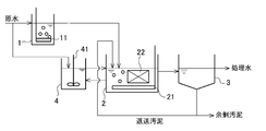
- FIGS. 1 to 5 are system diagrams showing an embodiment of a biological treatment method and apparatus for organic wastewater according to the first invention.
- 1 is a first biological treatment tank
- 2 is a second biological treatment tank
- 3 is a sedimentation tank
- 4 is an oxygen-free tank
- 5 is a membrane separator
- 11 and 21 are air diffusers
- 22 is a micro animal.
- a holding carrier, 41 is a stirring means
- 42 is a carrier, and members having the same functions in FIGS.
- raw water organic wastewater
- 70% or more, desirably 80% of the organic component (soluble BOD) is obtained by dispersible bacteria (non-aggregating bacteria). More preferably, 90% or more is oxidatively decomposed.
- the pH of the first biological treatment tank 1 is 6 or more, preferably 8 or less. However, when the raw water contains a large amount of oil, the pH may be 8 or more.
- the water flow to the first biological treatment tank 1 is usually a transient type, and the BOD volume load of the first biological treatment tank 1 is 1 kg / m 3 / d or more, for example, 1 to 20 kg / m 3 / d,
- the HRT raw water retention time
- the HRT raw water retention time
- treated water dominated by dispersible bacteria can be obtained, and by shortening the HRT, Wastewater with a low BOD concentration can be treated with a high load.
- the shape of the carrier is arbitrary such as a spherical shape, a pellet shape, a hollow cylindrical shape, a thread shape, a plate shape, etc., and the size is also arbitrary within a diameter of about 0.1 to 10 mm. is there.
- the material of the carrier is any material such as a natural material, an inorganic material, and a polymer material, and a gel material may be used.
- carrier added to the 1st biological treatment tank 1 is high, a dispersal microbe does not produce
- the first biological treatment tank 1 may suppress the growth of filamentous bacteria by setting the dissolved oxygen (DO) concentration to 1 mg / L or less, preferably 0.5 mg / L or less.
- DO dissolved oxygen
- the decomposition rate of the organic component in the first biological treatment tank 1 is not 100% but 95% or less, desirably 85 to 90%.
- the treated water in the first biological treatment tank 1 (first biological treated water) is passed through the second biological treatment tank 2 in the subsequent stage, where the remaining organic components are oxidatively decomposed and the dispersible bacteria are self-degraded. Reduce excess sludge through predation of micro-animals.
- this 2nd biological treatment tank 2 is good also as a multistage structure of two or more tanks.
- the holding amount of the micro animal in the tank is increased.
- the shape of the carrier 22 provided in the second biological treatment tank 2 is arbitrary, such as a spherical shape, a pellet shape, a hollow cylindrical shape, and a thread shape, and the size may be about 0.1 to 10 mm.
- a fixed bed may be used, and the shape of the carrier 22 in that case is arbitrary, such as a thread shape or a plate shape.
- the material of the carrier 22 is arbitrary such as a natural material, an inorganic material, or a polymer material, and a gel material may be used.
- a large amount of scaffolding for maintaining micro-animals is required, so the filling rate of the carrier to be added varies depending on the type and material of the fluidized bed and fixed bed. It is desirable to make it 40%.
- the second biological treatment tank 2 not only the filtration and predation type micro animals that prey on the dispersed cells, but also the aggregate predation type micro animals that can prey on the floc sludge. Since the latter prey on flocs while swimming, if prioritized, sludge is eaten and becomes sludge in which fine floc pieces are scattered. The floc pieces increase the concentration of treated water SS in sedimentation basin type activated sludge, and membrane clogging occurs in membrane activated sludge.
- an oxygen-free tank 4 is provided, and sludge extracted from the second biological treatment tank 2 is retained in the oxygen-free tank 4 for a predetermined time, thereby inhibiting the growth of the swimming micro-animals. Stabilize biota.
- the second biological treatment tank 2 is provided with a micro-animal holding carrier 22, and the filtered predatory micro-animal is fixed on the carrier 22 side. , So that the growth of filtered predatory microanimals is not inhibited.
- the sludge extracted from the second biological treatment tank 2 and treated in the anoxic tank 4 is returned to the second biological treatment tank 2.
- the amount of sludge withdrawn from the second biological treatment tank 2 to the oxygen-free tank 4 and the sludge residence time in the oxygen-free tank 4 are appropriately determined according to the treatment status. 1/30 times the amount / day or more, and the sludge residence time in the oxygen-free tank 4 is preferably 0.5 hours or more.
- the ORP in the anaerobic tank 4, the ORP needs to be 0 mV or less in order to inhibit the growth of minute animals. Therefore, it is desirable not to perform aeration in the oxygen-free tank 4 but only to mechanical stirring. Moreover, in order to accelerate
- a carrier may be added to the oxygen-free tank 4 in order to stably advance the ORP reduction (denitrification reaction, acid generation reaction) in the oxygen-free tank 4. If the ORP in the anaerobic tank 4 is low, the decrease in the activity of the swimming micro-animal is promoted, so the residence time of the second biological treatment tank sludge in the anoxic tank 4 can be shortened, and the anaerobic tank 4 can be downsized. can do.
- the shape of the carrier to be added is arbitrary such as a spherical shape, a pellet shape, a hollow cylindrical shape, and a thread shape, and the size is arbitrary with a diameter of about 0.1 to 10 mm.
- a fixed bed may be used, and the shape of the carrier 22 in that case is arbitrary, such as a thread shape or a plate shape.
- the material may be a natural material, an inorganic material, a polymer material or the like, and a gel material may be used.
- the filling rate varies depending on the type of fluidized bed and fixed bed and the material, but is preferably 0.5 to 40%.
- the tank sludge is periodically replaced, that is, in order to thin out minute animals and feces, the SRT (solid content retention time) is 60 days or less, preferably 45 days or less, and more preferably It is desirable to control it within a range from 10 days to 45 days.
- SRT solid content retention time
- SRT (sludge concentration in tank ⁇ aeration tank volume) ⁇ (drawn sludge concentration ⁇ amount drawn per day), and sludge concentration in tank (MLSS) indicates the concentration of floating sludge, exclude.
- the oxidative decomposition is performed in the subsequent treatment tank. It is known that when oxidative degradation of organic matter by bacteria occurs in the second biological treatment tank 2 where a large amount of micro animals are present, as a countermeasure to escape from predation of micro animals, it grows in a form that is difficult to be predated. The bacterial group thus grown is not preyed on by the micro-animals, and their decomposition depends only on autolysis, and the effect of reducing the amount of sludge generated is reduced.
- MLSS refers to the concentration of suspended sludge and does not include sludge for carrier adhesion.
- the treated water from the second biological treatment tank 2 is then solid-liquid separated into sludge and treated water in the settling tank 3, the separated water is taken out as treated water, and a part of the separated sludge is returned to the sludge. To the second biological treatment tank 2 and the remainder is discharged out of the system as excess sludge.
- a membrane separation device may be used as a solid-liquid separation means instead of the precipitation tank 3.
- a membrane separation device Conventionally, in membrane separation treatment of activated sludge, reduction of flux due to clogging of the membrane and chemical cleaning have been problems, but according to the present invention, sudden dispersion of sludge can be prevented, Operation management of the separation device can be facilitated.
- a part of the first biological treatment tank treated water from the first biological treatment tank 1, for example, about 10 to 20% is introduced into the anoxic tank 4, and the remaining part is supplied to the second biological treatment tank 2.
- the point of introduction is different from that shown in FIG.
- the ORP of the anoxic tank 4 is lowered, and the growth inhibition effect of the minute animals in the anoxic tank 4 is reduced. Can be increased.
- the embodiment shown in FIG. 3 is different from the embodiment shown in FIG. 1 in that a part of raw water, for example, about 10 to 20% is directly introduced into the anoxic tank 4 and the remainder is introduced into the first biological treatment tank 1.
- a part of raw water for example, about 10 to 20%
- the ORP of the anoxic tank 4 can be lowered and the effect of inhibiting the growth of micro animals in the anoxic tank 4 can be enhanced. .
- the embodiment shown in FIG. 4 uses a membrane separation device 5 in place of the sedimentation tank 3, takes out the permeated water of the membrane separation apparatus 5 as treated water, returns the concentrated water to the second biological treatment tank 2, and removes excess sludge.
- the point which was made to pull out directly from the 2nd biological treatment tank 2 differs from the aspect shown in FIG. 1, and others are set as the same structure.
- the membrane separation device 5 is used as the solid-liquid separation means, according to the first invention, since the growth of the aggregate predation type micro-animal is suppressed, as in the conventional activated sludge membrane separation process. The problem of clogging of the membrane is reduced, the membrane flux is stabilized, and the frequency of chemical cleaning can be reduced.
- the carrier 42 is added to the anaerobic tank 4, and the other configuration is the same.
- the ORP of the oxygen-free tank 4 can be reduced, and the effect of inhibiting the growth of micro animals in the oxygen-free tank 4 can be enhanced.
- the first biological treatment tank and the second biological treatment tank may have a multi-stage configuration with two or more stages as described above. Therefore, in the first invention, the biological treatment tank may be provided in three or more stages.
- a solid-liquid separation means a sedimentation tank, a membrane separation apparatus, a flotation separation tank, or the like may be used.
- a membrane separation type aerobic treatment may be performed.
- the biological treatment tank after the second biological treatment tank is provided with the micro animal holding carrier, and the biological treatment tank sludge after the second biological treatment tank is treated in the anoxic tank.
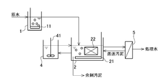
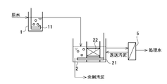
- FIGS. 6 to 8 are system diagrams showing an embodiment of the biological treatment method and apparatus for organic waste water of the second invention.
- 1 is a first biological treatment tank
- 2 is a second biological treatment tank
- 4 is an oxygen-free tank
- 5 is a membrane separation device
- 11 and 21 are air diffusers
- 22 is a micro-animal holding carrier
- 41 is Members that are stirring means and have the same function in FIGS. 6 to 8 are given the same reference numerals.
- raw water organic wastewater
- 70% or more preferably 80% of the organic component (soluble BOD) is obtained by dispersible bacteria (non-aggregating bacteria). More preferably, 90% or more is oxidatively decomposed.
- the pH of the first biological treatment tank 1 is 6 or more, preferably 8 or less. However, when the raw water contains a large amount of oil, the pH may be 8 or more.
- the water flow to the first biological treatment tank 1 is usually a transient type, and the BOD volume load of the first biological treatment tank 1 is 1 kg / m 3 / d or more, for example, 1 to 20 kg / m 3 / d,
- the HRT raw water retention time
- the HRT raw water retention time
- treated water dominated by dispersible bacteria can be obtained, and by shortening the HRT, Wastewater with a low BOD concentration can be treated with a high load.
- the shape of the carrier is arbitrary such as a spherical shape, a pellet shape, a hollow cylindrical shape, a thread shape, a plate shape, etc., and the size is also arbitrary within a diameter of about 0.1 to 10 mm. is there.
- the material of the carrier is any material such as a natural material, an inorganic material, and a polymer material, and a gel material may be used.
- carrier added to the 1st biological treatment tank 1 is high, a dispersal microbe does not produce
- the first biological treatment tank 1 may suppress the growth of filamentous bacteria by setting the dissolved oxygen (DO) concentration to 1 mg / L or less, preferably 0.5 mg / L or less.
- DO dissolved oxygen
- the decomposition rate of the organic component in the first biological treatment tank 1 is not 100% but 95% or less, desirably 85 to 90%.
- the treated water in the first biological treatment tank 1 (first biological treated water) is passed through the second biological treatment tank 2 in the subsequent stage, where the remaining organic components are oxidatively decomposed and the dispersible bacteria are self-degraded. And reduce excess sludge by predation of micro-animals.
- this 2nd biological treatment tank 2 is good also as a multistage structure of two or more tanks.
- the membrane separation device may be either a tank internal type or a tank external type, but by using the tank external type, clogging of the membrane by dispersal bacteria whose predation was delayed at high loads is prevented. be able to.
- the micro-animals particularly the dispersal bacteria, can be efficiently eaten to contribute to the solid-liquid separation of sludge and the quality of the treated water. Increase the amount of filterable predatory microanimals that can be retained in the tank.
- the second biological treatment tank 2 not only the filtration and predation type micro animals that prey on the dispersed cells, but also the aggregate predation type micro animals that can prey on the floc sludge. Since the latter prey on flocs while swimming, if prioritized, sludge is eaten and becomes sludge in which fine floc pieces are scattered. The floc pieces cause membrane clogging in the membrane activated sludge method. Therefore, in the second invention, in this second biological treatment tank 2, the tank sludge is periodically replaced, that is, in order to thin out minute animals and feces, the SRT (solid content retention time) is desirably 60 days or less, and more desirably.
- sludge concentration (MLSS) in the second biological treatment tank 2 is 2000 mg / L or less, SRT> 60 days may be set.
- SRT (tank sludge concentration ⁇ aeration tank volume) ⁇ (drawn sludge concentration ⁇ amount drawn per day), and the sludge concentration in the tank (MLSS) indicates the concentration of floating sludge. exclude.
- a micro-animal holding carrier 22 is provided in the second biological treatment tank 2 in order to maintain the filtration predation type micro-animal that prey on the dispersed cells in the second biological treatment tank 2.
- the carrier provided in the second biological treatment tank 2 is not a fluid carrier, but at least a part of the carrier is fixed to any one of the bottom surface, the side surface, the upper part and the like of the second biological treatment tank 2.
- a fixed carrier is preferred.
- the shape of the carrier 22 is arbitrary such as a thread shape, a plate shape, or a strip shape.
- the material of the carrier 22 is arbitrary such as a natural material, an inorganic material, or a polymer material, and a gel material may be used.
- a porous urethane foam is desirable, for example, a plate shape or a strip shape with a thickness of 100 to 400 cm ⁇ 50 to 200 cm ⁇ 0.5 to 5 cm, and it is desirable to install it where aeration air does not contact.
- the filling rate of the carrier is excessively high, mixing in the tank, sludge decay, etc. may occur.
- the filling rate is preferably about 0.1 to 20%.
- the oxidative decomposition is performed in a subsequent treatment tank. It is known that when oxidative degradation of organic matter by bacteria occurs in the second biological treatment tank 2 where a large amount of micro animals are present, as a countermeasure to escape from predation of micro animals, it grows in a form that is difficult to be predated. The bacterial group thus grown is not preyed on by the micro-animals, and their decomposition depends only on autolysis, and the effect of reducing the amount of sludge generated is reduced.
- MLSS refers to the concentration of suspended sludge and does not include sludge for carrier adhesion.
- the treated water from the second biological treatment tank 2 is fed to the outside membrane separation device 5, and the permeated water of the membrane separation device 5 is taken out as treated water, and the concentrated water is treated with the second biological treatment. It returns to the upstream of the tank 2, and the excess sludge is extracted directly from the second biological treatment tank 2.
- the membrane separation apparatus 5 since the growth of the aggregate predation type micro-animal is suppressed, Membrane clogging problems are alleviated, membrane flux can be stabilized and chemical cleaning frequency can be reduced, and sudden sludge dispersion can be prevented, facilitating operation management of membrane separation equipment. be able to.
- the embodiment shown in FIG. 7 is different from the embodiment shown in FIG. 6 in that a part of raw water, for example, about 5 to 50% is introduced directly into the second biological treatment tank 2 without passing through the first biological treatment tank 1.
- the other configurations are the same. In this way, by introducing a part of the raw water directly into the second biological treatment tank 2, an effect of avoiding the load shortage of the second biological treatment tank when the raw water fluctuates (when the load is reduced) is achieved.
- the second biological treatment tank 2 is provided with a micro-animal holding carrier 22, and since a certain amount of the filter predation type micro animal is held on the carrier 22 side, the growth of the filter predation type micro animal is inhibited. None happen.
- the sludge extracted from the second biological treatment tank 2 and treated in the anoxic tank 4 is returned to the second biological treatment tank 2.
- the amount of sludge withdrawn from the second biological treatment tank 2 to the oxygen-free tank 4 and the sludge residence time in the oxygen-free tank 4 are appropriately determined according to the treatment status. It is preferable that the sludge residence time in the anaerobic tank 4 is 0.5 hour or more.
- the ORP in the anaerobic tank 4, the ORP needs to be 0 mV or less in order to inhibit the growth of minute animals. Therefore, it is desirable not to perform aeration in the oxygen-free tank 4 but only to mechanical stirring. Moreover, in order to accelerate
- a carrier may be added to the oxygen-free tank 4 in order to stably advance the ORP reduction (denitrification reaction, acid generation reaction) in the oxygen-free tank 4. If the ORP in the anaerobic tank 4 is low, the decrease in the activity of the swimming micro-animal is promoted, so the residence time of the second biological treatment tank sludge in the anoxic tank 4 can be shortened, and the anaerobic tank 4 can be downsized. can do.
- the shape of the carrier to be added is arbitrary such as a spherical shape, a pellet shape, a hollow cylindrical shape, and a thread shape, and the size is arbitrary with a diameter of about 0.1 to 10 mm.
- a fixed bed may be used, and the shape of the carrier 22 in that case is arbitrary, such as a thread shape or a plate shape.
- the material may be a natural material, an inorganic material, a polymer material or the like, and a gel material may be used.
- the filling rate varies depending on the type of fluidized bed and fixed bed and the material, but is preferably 0.5 to 40%.
- the first biological treatment tank and the second biological treatment tank may have a multi-stage configuration with two or more stages as described above. Therefore, in the second invention, the biological treatment tank may be provided in three or more stages.
- the second invention by providing a micro-animal holding carrier in the biological treatment tanks subsequent to the second biological treatment tank, the priority of the aggregate predation type micro-animal is suppressed, so that sludge It is possible to achieve both weight loss and improvement of the quality of treated water, and by separating the biologically treated water after this second biological treatment tank by solid-liquid separation with a membrane separator, it prevents the membrane of the membrane separator from being blocked, Stable and high-load processing is possible.
- Example I-1 As shown in FIG. 1, a first biological treatment tank 1 with a capacity of 3.6 L, a second biological treatment tank 2 with a capacity of 15 L, an anoxic tank 4 with a capacity of 5 L, and a precipitation tank 3 with a capacity of 5 L
- the organic waste water according to the present invention was treated using an experimental apparatus in which the two were connected.
- the raw water contains artificial substrates of COD Cr : 1000 mg / L, BOD: 640 mg / L.
- the treatment conditions for each biological treatment tank were as follows.
- a plate-like polyurethane foam was used as the carrier 12 of the second biological treatment tank 2. Further, the BOD volumetric load in the entire apparatus was 0.75 kg-BOD / m 3 / d, and the HRT in the entire apparatus was 21 h.
- the sludge floc in the second biological treatment tank 2 and the filter-precipitating microanimals (Villus elegans, scallop) are prioritized on the carrier, and the sludge conversion rate is 0.1 kg-MLSS / kg-COD Cr. It was.
- the quality of the treated water (solid-liquid separated water in the precipitation tank 4) was always in good condition throughout the test period, with an SS concentration of less than 10 mg / L and a soluble COD Cr concentration of less than 30 mg / L.
- Example I-2 The treatment was performed under the same conditions as in Example I-1, except that a UF membrane was used as the membrane separation device instead of the precipitation tank, and the experimental device shown in FIG. 4 was used.
- the quality of the raw water, the treatment conditions of the first and second biological treatment tanks and anoxic tanks, and the overall BOD volumetric load and HRT are the same as in Example I-1.
- the sludge floc in the second biological treatment tank and the fixed filter predation type micro-animals were prioritized and the sludge conversion rate was 0.075 kg-MLSS / kg-COD Cr . .
- the quality of the treated water was always in good condition during the test period, with a soluble COD Cr concentration of less than 20 mg / L.
- there was almost no increase in transmembrane pressure and a stable flux could be maintained without chemical cleaning for one month or longer.
- Example I-1 The treatment was performed under the same conditions as in Example I-1, except that the anoxic tank was omitted and no carrier was provided in the second biological treatment tank.
- the quality of the raw water, the treatment conditions of the first and second biological treatment tanks, the overall BOD volumetric load and the HRT are the same as in Example I-1.
- the sludge conversion rate was 0.13 kg-MLSS / kg-COD Cr .
- aggregate predation type micro-animals Hele worms
- Example I-2 The treatment was performed under the same conditions as in Example I-2 except that the anoxic tank was omitted and no carrier was provided in the second biological treatment tank.
- the quality of the raw water, the treatment conditions of the first and second biological treatment tanks, the overall BOD volumetric load and the HRT are the same as in Example I-1.
- the sludge conversion rate was 0.12 kg-MLSS / kg-COD Cr .
- aggregate predation type micro-animals Hole worms
- transmembrane pressure increases frequently, and chemical cleaning of membranes is required once every two weeks throughout the test period. It became.
- Example II-1 As shown in FIG. 6, the present invention uses an experimental apparatus in which a first biological treatment tank 1 having a capacity of 3.6 L, a second biological treatment tank 2 having a capacity of 15 L, and a UF membrane separation device 5 are connected. Treatment of organic wastewater by The raw water contains artificial substrates of COD Cr : 1000 mg / L, BOD: 640 mg / L.
- the treatment conditions for each biological treatment tank were as follows.
- plate-like polyurethane foam (15 mm ⁇ 300 mm ⁇ 50 mm / 1 sheet) is used as the carrier 12 of the second biological treatment tank 2, and it is in a position symmetrical to the air diffusion tube 21 with respect to the vertical plane at the center of the tank.
- the bottom and the left and right sides were fixed to the tank wall surface.
- the BOD volumetric load in the entire apparatus was 0.75 kg-BOD / m 3 / d
- the HRT in the entire apparatus was 21 h.
- the sludge floc in the second biological treatment tank 2 and the filter-precipitating microanimals (Villus elegans, scallop) are prioritized on the carrier, and the sludge conversion rate is 0.1 kg-MLSS / kg-COD Cr. It was.
- the quality of the treated water (permeated water of the membrane separation device 5) was always in good condition throughout the test period, with a soluble COD Cr concentration of less than 20 mg / L. Further, there was almost no increase in the transmembrane pressure difference of the membrane separation device 5, and a stable flux could be maintained without chemical cleaning for one month or longer.
- Example II-1 The treatment was performed under the same conditions as in Example II-1 except that the first biological treatment tank was omitted, the capacity of the second biological treatment tank was 18.6 L, and no carrier was provided in the second biological treatment tank. .
- Raw water quality, DO and pH of the second biological treatment tank, overall BOD volumetric load and HRT are the same as in Example II-1.
- the sludge conversion rate was 0.20 kg-MLSS / kg-COD Cr .
- the aggregate predatory microanimals prevailed, and during that time, the transmembrane pressure difference increased, requiring chemical cleaning of the membrane once every two weeks.
- the process water is also worse, soluble COD Cr concentration was increased to more than 70 mg / L.
- Example II-2 As shown in FIG. 8, an anoxic tank 4 having a capacity of 5 L is provided, and after sludge in the second biological treatment tank 2 is extracted and treated in the anoxic tank 4, it is returned to the second biological treatment tank 2. Except for this, the treatment was performed under the same conditions as in Example II-1. The quality of raw water, the treatment conditions of the first and second biological treatment tanks, and the overall BOD volumetric load and HRT are the same as in Example II-1.
- the sludge floc in the second biological treatment tank and the fixed filter predation type micro-animals were prioritized and the sludge conversion rate was 0.075 kg-MLSS / kg-COD Cr . .
- the quality of the treated water was always in good condition during the test period with a soluble COD Cr concentration of less than 20 mg / L.
- the biological treatment method and apparatus for organic wastewater of the present invention can be used for treatment of organic wastewater in a wide concentration range including domestic wastewater, sewage, food factories and pulp factories.
Landscapes
- Life Sciences & Earth Sciences (AREA)
- Engineering & Computer Science (AREA)
- Water Supply & Treatment (AREA)
- Chemical & Material Sciences (AREA)
- Microbiology (AREA)
- Hydrology & Water Resources (AREA)
- Biodiversity & Conservation Biology (AREA)
- Environmental & Geological Engineering (AREA)
- Organic Chemistry (AREA)
- Chemical Kinetics & Catalysis (AREA)
- Botany (AREA)
- Biotechnology (AREA)
- Activated Sludge Processes (AREA)
- Purification Treatments By Anaerobic Or Anaerobic And Aerobic Bacteria Or Animals (AREA)
Abstract
Description
膜式活性汚泥法では、沈殿池型活性汚泥法に比べて汚泥濃度を高く維持し、高い容積負荷で運転することが可能である上に、沈殿池におけるような汚泥管理が不要で、良好な水質の処理水を得ることができるという利点がある。
また、活性汚泥処理を低負荷で運転した場合であっても、汚泥の解体で微細なSSが発生し、膜を閉塞させる。また、水温、負荷、SRT(固形分滞留時間)により、活性汚泥内でフロックを捕食する微小動物が急増すると、汚泥の微細化が促進され、処理水の悪化につながり、これを固液分離する膜分離装置の運転管理が困難になるという問題もある。
1)排水処理時に発生する汚泥の大幅な減量化
2)高負荷運転による処理効率の向上
3)安定した処理水質の維持
図1~5は第1発明の有機性排水の生物処理方法および装置の実施の形態を示す系統図である。
図1~5において、1は第一生物処理槽、2は第二生物処理槽、3は沈殿槽、4は無酸素槽、5は膜分離装置、11,21は散気管、22は微小動物保持担体、41は攪拌手段、42は担体であり、図1~5において同一機能を奏する部材には同一符号を付してある。
なお、第一生物処理槽1で溶解性有機物を完全に分解した場合、第二生物処理槽2ではフロックが形成されず、また、微小動物増殖のための栄養も不足し、圧密性の低い汚泥のみが優占化した生物処理槽となる。従って、第一生物処理槽1での有機成分の分解率は100%ではなく、95%以下、望ましくは85~90%となるようにすることが好ましい。
第二生物処理槽2に設ける担体22の形状は、流動床の場合は球状、ペレット状、中空筒状、糸状等任意であり、大きさも0.1~10mm程度の径で良い。固定床を用いても良く、その場合の担体22の形状は糸状、板状等任意である。また、担体22の材料は天然素材、無機素材、高分子素材等任意であり、ゲル状物質を用いても良い。
第二生物処理槽2では、微小動物を維持するための多量の足場が必要となることから、添加する担体の充填率は流動床、固定床の形式の違いや材質により異なるが、0.5~40%とすることが望ましい。
無酸素槽4に担体を添加する場合、その充填率は流動床、固定床の形式の違いや材質により異なるが、0.5~40%とすることが望ましい。
また、固液分離手段としては、沈殿槽の他、膜分離装置や浮上分離槽等を用いても良く、後段の生物処理槽は、生物処理槽と固液分離手段とを兼ねる膜浸漬型生物処理槽として、膜分離式好気処理を行ってもよい。
図6~8は第2発明の有機性排水の生物処理方法及び装置の実施の形態を示す系統図である。
図6~8において、1は第一生物処理槽、2は第二生物処理槽、4は無酸素槽、5は膜分離装置、11,21は散気管、22は微小動物保持担体、41は攪拌手段であり、図6~8において同一機能を奏する部材には同一符号を付してある。
なお、第一生物処理槽1で溶解性有機物を完全に分解した場合、第二生物処理槽2ではフロックが形成されず、また、微小動物増殖のための栄養も不足し、圧密性の低い汚泥のみが優占化した生物処理槽となる。従って、第一生物処理槽1での有機成分の分解率は100%ではなく、95%以下、望ましくは85~90%となるようにすることが好ましい。
その上で、分散状態の菌体を捕食する濾過捕食型微小動物を第二生物処理槽2内に維持するために、第二生物処理槽2内に微小動物保持担体22を設ける。即ち、この種の微小動物は汚泥フロックに固着し、系内に維持されるが、汚泥は一定の滞留時間で系外へ引き抜かれるため、供給源を系内に設ける必要がある。この時、担体を粒状や角型の流動床とすると、流動のための剪断力で、高濃度での安定保持ができないだけでなく、流動床で有機物が完全に処理され、汚泥フロックの微細化、これによる膜の閉塞につながる。
そこで、第2発明では、第二生物処理槽2に設ける担体として、流動担体ではなく、担体の少なくとも一部が、第二生物処理槽2の底面、側面、上部等のいずれかに固定された固定担体とすることが好ましい。その場合の担体22の形状は糸状、板状、短冊状等任意である。また、担体22の材料は天然素材、無機素材、高分子素材等任意であり、ゲル状物質を用いても良い。望ましくは多孔質のウレタンフォームであり、例えば100~400cm×50~200cm×0.5~5cm厚さの板状ないし短冊状とし、曝気空気があたらないところに設置することが望ましい。
無酸素槽4に担体を添加する場合、その充填率は流動床、固定床の形式の違いや材質により異なるが、0.5~40%とすることが望ましい。
[実施例I-1]
図1に示す如く、容量が3.6Lの第一生物処理槽1と、容量が15Lの第二生物処理槽2と、容量が5Lの無酸素槽4と、容量が5Lの沈殿槽3とを連結させた実験装置を用いて、本発明による有機性排水の処理を行った。原水は、CODCr:1000mg/L,BOD:640mg/Lの人口基質を含むものである。
各生物処理槽の処理条件は次の通りとした。
DO:0.5mg/L
BOD容積負荷:3.85kg-BOD/m3/d
HRT:4h
pH:7.0
<第二生物処理槽>
DO:4mg/L
担体充填率:2%
HRT:17h
SRT:30日
pH:7.0
<無酸素槽>
ORP:-100mV
HRT(=SRT):12h
また、装置全体でのBOD容積負荷は0.75kg-BOD/m3/dであり、装置全体でのHRTは21hであった。
沈殿槽の代りに膜分離装置としてUF膜を用い、図4に示す実験装置としたこと以外は実施例I-1と同様の条件で処理を行った。原水の水質、第一,第二生物処理槽及び無酸素槽の処理条件、並びに全体のBOD容積負荷及びHRTは実施例I-1と同一である。
処理水(膜分離装置の透過水)水質は、溶解性CODCr濃度が20mg/L未満と、試験期間中、常時良好な状態を維持していた。また、膜間差圧の上昇はほとんど無く、1ヶ月以上薬品洗浄を行わなくても、安定したフラックスを維持することができた。
無酸素槽を省略し、第二生物処理槽に担体を設けなかったこと以外は実施例I-1と同様の条件で処理を行った。
原水の水質、第一、第二生物処理槽の処理条件並びに全体のBOD容積負荷及びHRTは実施例I-1と同一である。
その結果、汚泥転換率は0.13kg-MLSS/kg-CODCrとなった。しかしながら、1ヶ月おきに、凝集体捕食型微小動物(ハオリワムシ)が優先化し、その間は、処理水SS濃度が80mg/L、溶解性CODCrが150mg/Lまで上昇した。
無酸素槽を省略し、第二生物処理槽に担体を設けなかったこと以外は実施例I-2と同様の条件で処理を行った。
原水の水質、第一、第二生物処理槽の処理条件並びに全体のBOD容積負荷及びHRTは実施例I-1と同一である。
その結果、汚泥転換率は0.12kg-MLSS/kg-CODCrとなった。しかしながら、1ヶ月おきに、凝集体捕食型微小動物(ハオリワムシ)が優先化し、その間は、膜間差圧の上昇が頻繁に起こり、試験期間を通じ、2週間に1回の膜の薬品洗浄が必要となった。
[実施例II-1]
図6に示す如く、容量が3.6Lの第一生物処理槽1と、容量が15Lの第二生物処理槽2と、UF膜分離装置5とを連結させた実験装置を用いて、本発明による有機性排水の処理を行った。原水は、CODCr:1000mg/L,BOD:640mg/Lの人口基質を含むものである。
各生物処理槽の処理条件は次の通りとした。
DO:0.5mg/L
BOD容積負荷:3.85kg-BOD/m3/d
HRT:4h
pH:7.0
<第二生物処理槽>
DO:4mg/L
担体充填率:2%
HRT:17h
SRT:30日
pH:7.0
また、装置全体でのBOD容積負荷は0.75kg-BOD/m3/dであり、装置全体でのHRTは21hであった。
処理水(膜分離装置5の透過水)水質は、溶解性CODCr濃度が20mg/L未満と、試験期間中、常時良好な状態を維持していた。
また、膜分離装置5の膜間差圧の上昇はほとんど無く、1ヶ月以上薬品洗浄を行わなくても、安定したフラックスを維持することができた。
第一生物処理槽を省略し、第二生物処理槽の容量を18.6Lとし、第二生物処理槽に担体を設けなかったこと以外は実施例II-1と同様の条件で処理を行った。
原水の水質、第二生物処理槽のDO及びpH、全体のBOD容積負荷及びHRTは実施例II-1と同一である。
その結果、汚泥転換率は0.20kg-MLSS/kg-CODCrとなった。しかしながら、1ヶ月おきに、凝集体捕食型微小動物(ハオリワムシ)が優先化し、その間は、膜間差圧の上昇で、2週間に1回の膜の薬品洗浄が必要となった。加えて、処理水質も、悪化し、溶解性CODCr濃度が70mg/L以上まで上昇した。
図8に示す如く、容量が5Lの無酸素槽4を設け、第二生物処理槽2内の汚泥を引き抜いて無酸素槽4で処理した後、第二生物処理槽2に返送するようにしたこと以外は実施例II-1と同様の条件で処理を行った。原水の水質、第一及び第二生物処理槽の処理条件、並びに全体のBOD容積負荷及びHRTは実施例II-1と同一である。
無酸素槽4の処理条件は以下の通りとした。
<無酸素槽>
ORP:-100mV
HRT(=SRT):12h
処理水水質は、溶解性CODCr濃度が20mg/L未満と、試験期間中、常時良好な状態を維持していた。また、膜間差圧の上昇はほとんど無く、1ヶ月以上薬品洗浄を行わなくても、安定したフラックスを維持することができた。
なお、本出願は、2010年3月31日付で出願された日本特許出願(特願2010-083136)、2010年7月21日付で出願された日本特許出願(特願2010-164087)、2011年3月2日付で出願された日本特許出願(特願2011-044797)及び2011年3月2日付で出願された日本特許出願(特願2011-044798)に基づいており、その全体が引用により援用される。
2 第二生物処理槽
3 沈殿槽
4 無酸素槽
5 膜分離装置
Claims (26)
- 二段以上の多段に設けられた好気性生物処理槽の第一生物処理槽に有機性排水を導入して細菌により生物処理し、第一生物処理槽からの分散状態の細菌を含む第一生物処理水を第二生物処理槽以降の生物処理槽に通水して生物処理する有機性排水の生物処理方法において、
該第二生物処理槽以降の生物処理槽に微小動物を保持する担体を設けると共に、該第二生物処理槽以降の生物処理槽内の汚泥の一部を引き抜いて無酸素槽で処理した後該第二生物処理槽以降の生物処理槽に返送することを特徴とする有機性排水の生物処理方法。 - 請求項1において、前記第一生物処理水の少なくとも一部を前記無酸素槽を経由して前記第二生物処理槽以降の生物処理槽に通水することを特徴とする有機性排水の生物処理方法。
- 請求項1又は2において、前記有機性排水の一部を前記無酸素槽に導入し、残部を前記第一生物処理槽に導入することを特徴とする有機性排水の生物処理方法。
- 請求項1ないし3のいずれか1項において、前記無酸素槽が担体を保持することを特徴とする有機性排水の生物処理方法。
- 請求項1ないし4のいずれか1項において、前記該第二生物処理槽以降の生物処理槽に微小動物を保持する担体が設けられていることを特徴とする有機性排水の生物処理方法。
- 請求項1ないし5のいずれか1項において、前記第二生物処理槽以降の生物処理槽のSRT(固形分滞留時間)が60日以下となるように汚泥を引き抜くことを特徴とする有機性排水の生物処理方法。
- 請求項1ないし6のいずれか1項において、前記第二生物処理槽以降の生物処理槽の処理水を固液分離し、分離汚泥の少なくとも一部を前記第二生物処理槽以降の生物処理槽に返送することを特徴とする有機性排水の生物処理方法。
- 二段以上の多段に設けられた好気性生物処理槽を備え、第一生物処理槽に有機性排水を導入して細菌により生物処理し、第一生物処理槽からの分散状態の細菌を含む第一生物処理水を第二生物処理槽以降の生物処理槽に通水して生物処理する有機性排水の生物処理装置において、
該第二生物処理槽以降の生物処理槽に微小動物を保持する担体が設けられており、該第二生物処理槽以降の生物処理槽内の汚泥の一部を引き抜いて処理した後該第二生物処理槽以降の生物処理槽に返送する無酸素槽を設けたことを特徴とする有機性排水の生物処理装置。 - 請求項8において、前記第一生物処理水の少なくとも一部を前記無酸素槽を経由して前記第二生物処理槽以降の生物処理槽に通水する手段を有することを特徴とする有機性排水の生物処理装置。
- 請求項8又は9において、前記有機性排水の一部を前記無酸素槽に導入する手段と、該有機性排水の残部を前記第一生物処理槽に導入する手段を有することを特徴とする有機性排水の生物処理装置。
- 請求項8ないし10のいずれか1項において、前記無酸素槽に担体が保持されていることを特徴とする有機性排水の生物処理装置。
- 請求項8ないし11のいずれか1項において、前記該第二生物処理槽以降の生物処理槽に微小動物を保持する担体が設けられていることを特徴とする有機性排水の生物処理装置。
- 請求項8ないし12のいずれか1項において、前記第二生物処理槽以降の生物処理槽のSRT(固形分滞留時間)が60日以下となるように汚泥が引き抜かれることを特徴とする有機性排水の生物処理装置。
- 請求項8ないし13のいずれか1項において、前記第二生物処理槽以降の生物処理槽の処理水を固液分離し、分離汚泥の少なくとも一部を前記第二生物処理槽以降の生物処理槽に返送する手段を有することを特徴とする有機性排水の生物処理装置。
- 二段以上の多段に設けられた好気性生物処理槽の第一生物処理槽に有機性排水を導入して細菌により生物処理し、第一生物処理槽からの分散状態の細菌を含む第一生物処理水を第二生物処理槽以降の生物処理槽に通水して生物処理し、該第二生物処理槽以降の生物処理槽の処理水を固液分離する有機性排水の生物処理方法において、
該第二生物処理槽以降の生物処理槽に微小動物を保持する担体を設けると共に、
該第二生物処理槽以降の生物処理槽の処理水の固液分離を膜分離処理により行うことを特徴とする有機性排水の生物処理方法。 - 請求項15において、前記膜分離処理を槽外型膜分離装置で行うことを特徴とする有機性排水の生物処理方法。
- 請求項15又は16において、前記第二生物処理槽以降の生物処理槽内に設けられた担体が該生物処理槽に固定された担体であることを特徴とする有機性排水の生物処理方法。
- 請求項15ないし17のいずれか1項において、前記有機性排水の一部を前記第一生物処理槽を経ることなく前記第二生物処理槽以降の生物処理槽に導入することを特徴とする有機性排水の生物処理方法。
- 請求項15ないし18のいずれか1項において、前記第二生物処理槽以降の生物処理槽のSRT(固形分滞留時間)が60日以下となるように汚泥を引き抜くことを特徴とする有機性排水の生物処理方法。
- 請求項15ないし19のいずれか1項において、前記第二生物処理槽以降の生物処理槽内の汚泥の一部を引き抜いて無酸素槽で処理した後該第二生物処理槽以降の生物処理槽に返送することを特徴とする有機性排水の生物処理方法。
- 二段以上の多段に設けられた好気性生物処理槽を備え、第一生物処理槽に有機性排水を導入して細菌により生物処理し、第一生物処理槽からの分散状態の細菌を含む第一生物処理水を第二生物処理槽以降の生物処理槽に通水して生物処理し、第二生物処理槽以降の生物処理槽の処理水を固液分離することを特徴とする有機性排水の生物処理装置において、
該第二生物処理槽以降の生物処理槽に微小動物を保持する担体が設けられており、
該第二生物処理槽以降の生物処理槽の処理水の固液分離手段として膜分離処理装置を備えることを特徴とする有機性排水の生物処理装置。 - 請求項21において、前記膜分離装置が槽外型膜分離装置であることを特徴とする有機性排水の生物処理装置。
- 請求項21又は22において、前記第二生物処理槽以降の生物処理槽内に設けられた担体が該生物処理槽に固定された担体であることを特徴とする有機性排水の生物処理装置。
- 請求項21ないし23のいずれか1項において、前記有機性排水の一部を前記第一生物処理槽を経ることなく前記第二生物処理槽以降の生物処理槽に導入する手段を有することを特徴とする有機性排水の生物処理装置。
- 請求項21ないし24のいずれか1項において、前記第二生物処理槽以降の生物処理槽のSRT(固形分滞留時間)が60日以下となるように汚泥が引き抜かれることを特徴とする有機性排水の生物処理装置。
- 請求項21ないし25のいずれか1項において、前記第二生物処理槽以降の生物処理槽内の汚泥の一部を引き抜いて処理した後該第二生物処理槽以降の生物処理槽に返送する無酸素槽を設けたことを特徴とする有機性排水の生物処理装置。
Priority Applications (3)
| Application Number | Priority Date | Filing Date | Title |
|---|---|---|---|
| KR1020187007823A KR20180031085A (ko) | 2010-03-31 | 2011-03-02 | 유기성 배수의 생물 처리 방법 및 장치 |
| CN201180013652.3A CN102791640B (zh) | 2010-03-31 | 2011-03-02 | 有机性排水的生物处理方法及装置 |
| KR1020127025769A KR20130040800A (ko) | 2010-03-31 | 2011-03-02 | 유기성 배수의 생물 처리 방법 및 장치 |
Applications Claiming Priority (8)
| Application Number | Priority Date | Filing Date | Title |
|---|---|---|---|
| JP2010-083136 | 2010-03-31 | ||
| JP2010083136 | 2010-03-31 | ||
| JP2010164087 | 2010-07-21 | ||
| JP2010-164087 | 2010-07-21 | ||
| JP2011044798A JP5935236B2 (ja) | 2010-03-31 | 2011-03-02 | 有機性排水の生物処理方法および装置 |
| JP2011-044798 | 2011-03-02 | ||
| JP2011044797 | 2011-03-02 | ||
| JP2011-044797 | 2011-03-02 |
Publications (1)
| Publication Number | Publication Date |
|---|---|
| WO2011122217A1 true WO2011122217A1 (ja) | 2011-10-06 |
Family
ID=44711946
Family Applications (1)
| Application Number | Title | Priority Date | Filing Date |
|---|---|---|---|
| PCT/JP2011/054748 Ceased WO2011122217A1 (ja) | 2010-03-31 | 2011-03-02 | 有機性排水の生物処理方法および装置 |
Country Status (1)
| Country | Link |
|---|---|
| WO (1) | WO2011122217A1 (ja) |
Cited By (3)
| Publication number | Priority date | Publication date | Assignee | Title |
|---|---|---|---|---|
| WO2013084711A1 (ja) * | 2011-12-09 | 2013-06-13 | 栗田工業株式会社 | 揺動性担体と、この揺動性担体を用いた有機性排水の生物処理装置及び方法 |
| CN104039715A (zh) * | 2012-01-06 | 2014-09-10 | 栗田工业株式会社 | 有机性排水的生物处理方法和装置 |
| WO2025229990A1 (ja) * | 2024-05-02 | 2025-11-06 | 栗田工業株式会社 | 有機性排水の生物処理方法 |
Citations (1)
| Publication number | Priority date | Publication date | Assignee | Title |
|---|---|---|---|---|
| JP2007105580A (ja) * | 2005-10-12 | 2007-04-26 | Kurita Water Ind Ltd | 有機性排水の生物処理方法および装置 |
-
2011
- 2011-03-02 WO PCT/JP2011/054748 patent/WO2011122217A1/ja not_active Ceased
Patent Citations (1)
| Publication number | Priority date | Publication date | Assignee | Title |
|---|---|---|---|---|
| JP2007105580A (ja) * | 2005-10-12 | 2007-04-26 | Kurita Water Ind Ltd | 有機性排水の生物処理方法および装置 |
Cited By (3)
| Publication number | Priority date | Publication date | Assignee | Title |
|---|---|---|---|---|
| WO2013084711A1 (ja) * | 2011-12-09 | 2013-06-13 | 栗田工業株式会社 | 揺動性担体と、この揺動性担体を用いた有機性排水の生物処理装置及び方法 |
| CN104039715A (zh) * | 2012-01-06 | 2014-09-10 | 栗田工业株式会社 | 有机性排水的生物处理方法和装置 |
| WO2025229990A1 (ja) * | 2024-05-02 | 2025-11-06 | 栗田工業株式会社 | 有機性排水の生物処理方法 |
Similar Documents
| Publication | Publication Date | Title |
|---|---|---|
| JP5994253B2 (ja) | 有機性排水の生物処理装置及び方法 | |
| KR20100061808A (ko) | 높은 용존 산소 농도를 이용한 활성 슬러지 하수 처리용 시스템 | |
| JP5895663B2 (ja) | 有機性排水の生物処理方法 | |
| WO2012169381A1 (ja) | 有機性排水の生物処理方法および装置 | |
| JP5772337B2 (ja) | 有機性排水の生物処理方法及び装置 | |
| WO2007088860A1 (ja) | 有機性廃水の生物処理方法 | |
| JP5862597B2 (ja) | 有機性排水の生物処理方法および装置 | |
| JP5915643B2 (ja) | 有機性排水の生物処理方法および装置 | |
| JP5874741B2 (ja) | 有機性排水の生物処理方法及び装置 | |
| JP5786998B1 (ja) | 有機性排水の生物処理方法及び装置 | |
| WO2013084711A1 (ja) | 揺動性担体と、この揺動性担体を用いた有機性排水の生物処理装置及び方法 | |
| JP5935236B2 (ja) | 有機性排水の生物処理方法および装置 | |
| CN102791640B (zh) | 有机性排水的生物处理方法及装置 | |
| WO2011122217A1 (ja) | 有機性排水の生物処理方法および装置 | |
| JP4581551B2 (ja) | 有機性排水の生物処理方法 | |
| WO2017064982A1 (ja) | 有機性排水の生物処理方法 | |
| WO2015045094A1 (ja) | 有機性排水の生物処理方法 | |
| JP6020620B2 (ja) | 有機性排水の生物処理方法および装置 | |
| WO2012073752A1 (ja) | 有機性排水の生物処理方法及び装置 | |
| JP2006247494A (ja) | 有機性排水の生物処理方法及び装置 | |
| JP7228487B2 (ja) | 有機性廃水の処理方法及び有機性廃水の処理装置 | |
| TW202535788A (zh) | 有機性廢水的生物處理方法 | |
| JP2021181062A (ja) | 有機性廃水の処理方法及び有機性廃水の処理装置 | |
| TW201512108A (zh) | 有機性廢水的生物處理方法 |
Legal Events
| Date | Code | Title | Description |
|---|---|---|---|
| WWE | Wipo information: entry into national phase |
Ref document number: 201180013652.3 Country of ref document: CN |
|
| 121 | Ep: the epo has been informed by wipo that ep was designated in this application |
Ref document number: 11762457 Country of ref document: EP Kind code of ref document: A1 |
|
| ENP | Entry into the national phase |
Ref document number: 20127025769 Country of ref document: KR Kind code of ref document: A |
|
| NENP | Non-entry into the national phase |
Ref country code: DE |
|
| 122 | Ep: pct application non-entry in european phase |
Ref document number: 11762457 Country of ref document: EP Kind code of ref document: A1 |