WO2011122173A1 - トレー、光学製品の収容構造及び光学製品の収容方法 - Google Patents
トレー、光学製品の収容構造及び光学製品の収容方法 Download PDFInfo
- Publication number
- WO2011122173A1 WO2011122173A1 PCT/JP2011/053804 JP2011053804W WO2011122173A1 WO 2011122173 A1 WO2011122173 A1 WO 2011122173A1 JP 2011053804 W JP2011053804 W JP 2011053804W WO 2011122173 A1 WO2011122173 A1 WO 2011122173A1
- Authority
- WO
- WIPO (PCT)
- Prior art keywords
- tray
- optical
- optical product
- hole
- flange portion
- Prior art date
- Legal status (The legal status is an assumption and is not a legal conclusion. Google has not performed a legal analysis and makes no representation as to the accuracy of the status listed.)
- Ceased
Links
Images



Classifications
-
- B—PERFORMING OPERATIONS; TRANSPORTING
- B65—CONVEYING; PACKING; STORING; HANDLING THIN OR FILAMENTARY MATERIAL
- B65D—CONTAINERS FOR STORAGE OR TRANSPORT OF ARTICLES OR MATERIALS, e.g. BAGS, BARRELS, BOTTLES, BOXES, CANS, CARTONS, CRATES, DRUMS, JARS, TANKS, HOPPERS, FORWARDING CONTAINERS; ACCESSORIES, CLOSURES, OR FITTINGS THEREFOR; PACKAGING ELEMENTS; PACKAGES
- B65D21/00—Nestable, stackable or joinable containers; Containers of variable capacity
- B65D21/02—Containers specially shaped, or provided with fittings or attachments, to facilitate nesting, stacking, or joining together
- B65D21/0201—Containers specially shaped, or provided with fittings or attachments, to facilitate nesting, stacking, or joining together stackable or joined together side-by-side
- B65D21/0204—Containers specially shaped, or provided with fittings or attachments, to facilitate nesting, stacking, or joining together stackable or joined together side-by-side and joined together by interconnecting formations forming part of the container, e.g. dove-tail, snap connections, hook elements
-
- B—PERFORMING OPERATIONS; TRANSPORTING
- B65—CONVEYING; PACKING; STORING; HANDLING THIN OR FILAMENTARY MATERIAL
- B65D—CONTAINERS FOR STORAGE OR TRANSPORT OF ARTICLES OR MATERIALS, e.g. BAGS, BARRELS, BOTTLES, BOXES, CANS, CARTONS, CRATES, DRUMS, JARS, TANKS, HOPPERS, FORWARDING CONTAINERS; ACCESSORIES, CLOSURES, OR FITTINGS THEREFOR; PACKAGING ELEMENTS; PACKAGES
- B65D85/00—Containers, packaging elements or packages, specially adapted for particular articles or materials
- B65D85/30—Containers, packaging elements or packages, specially adapted for particular articles or materials for articles particularly sensitive to damage by shock or pressure
- B65D85/38—Containers, packaging elements or packages, specially adapted for particular articles or materials for articles particularly sensitive to damage by shock or pressure for delicate optical, measuring, calculating or control apparatus
Definitions
- the present invention relates to a tray, an optical product housing structure, and an optical product housing method.
- optical products such as lenses are stored and transported in a highly airtight pallet configured by superposing first and second plates having different shapes (for example, Patent Documents). 1).
- the pallet includes a first through hole that exposes a part of the lens on the first plate, and a first support portion including a plurality of protrusions around the first through hole.
- a second through hole for exposing a part of the lens to the second plate, and a second support portion formed of a plurality of protrusions around the second through hole, and the first and second plates are overlapped.
- the outer periphery of the lens is supported by the side surfaces of the first and second support portions by fitting each other so that the tip portions of the first support portion and the second support portion do not abut each other when they are combined. It is configured.
- a concave portion 301 that is recessed from the upper surface 300 a to the lower surface 300 b side is formed in the tray 300, and a through hole 302 that exposes the optical surface 202 is formed at the center of the concave portion 301.
- the flange portion 201 of the lens 200 ⁇ / b> A is placed in the recess 301, and the optical surface 202 of the lens 200 ⁇ / b> A is placed in the through hole 302.
- the tray 300 is further placed on the upper surfaces of the lens 200A and the tray 300 thus arranged, and the lens 200B is similarly arranged on the placed tray 300.
- the flange portion 201 of the uppermost lens 200B has its outer peripheral surface and lower surface held by the recess 301, and the flange portion 201 is Is pressed from above by the lower surface of the tray 300.
- the lens 200A also holds the upper and lower surfaces and the outer peripheral surface of the flange portion 201 (see FIG. 7A).
- the pallet of patent document 1 is the structure which formed the 1st and 2nd support part which is a some protrusion in the 1st and 2nd plate, respectively, such 1st plate and 2nd
- the first and second support portions are protrusions, so that there is a problem that they are thin and easy to break.
- the first and second support portions are formed so as to protrude from the plate, so that the fitting between the first and second support portions is shifted. There is a possibility that the contained lens will pop out.
- the second plate as in the cited document 1 is not necessary, and the storage container can be configured by only one type of tray 300, but FIG. As shown in FIG. 7, the upper and lower trays 300 are turned upside down in a state where the multi-stage trays 300 are stacked in each process, and the uppermost tray 300 is removed and the optical surface is observed as shown in FIG. 7C. Cases arise. In such a case, since the uppermost tray 300 is removed from the uppermost lens 200A in the inverted state, the lens 200A is only placed on the lowermost tray 300, and the flange portion 201 of the lens 200A. The outer peripheral surface 201c is not held. For this reason, handling is inconvenient, such as the lens 200A being displaced, and improvement in convenience is required by making the storage container reversible.
- the present invention has been made in view of the above circumstances, can reduce costs, can reliably store optical products, and can be inverted upside down to improve convenience by making it reversible. It is an object of the present invention to provide a tray, an optical product housing structure, and an optical product housing method.
- a tray that accommodates optical products and can be stacked in multiple stages, It has a plate-like tray body, In the tray body, A recess that is recessed from the upper surface of the tray body toward the lower surface, and that accommodates the optical product; A through hole penetrating the upper and lower surfaces in the recess, and the optical surface of the optical product is disposed; A mounting portion that is formed around the through hole in the recess and on which the flange portion of the optical product is mounted; An outer peripheral holding portion formed on an inner wall surface forming the concave portion and holding an outer peripheral surface of the flange portion of the optical product; Around the through hole in the lower surface of the tray body, at least three protrusions that fall from the lower surface; A groove portion formed in a position corresponding to the protrusion portion on the outer periphery of the placement portion of the tray body, and into which the protrusion portion of the upper tray stacked on the upper portion of the tray body is inserted; A pressing portion that is
- an optical product is accommodated in a tray, and the tray is stacked in multiple stages.
- the tray includes a plate-like tray body, In the tray body, A recess that is recessed from the upper surface of the tray body toward the lower surface, and that accommodates the optical product; A through hole penetrating the upper and lower surfaces in the recess, and the optical surface of the optical product is disposed; A mounting portion that is formed around the through hole in the recess and on which the flange portion of the optical product is mounted; An outer peripheral holding portion formed on an inner wall surface forming the concave portion and holding an outer peripheral surface of the flange portion of the optical product; Around the through hole in the lower surface of the tray body, at least three protrusions that fall from the lower surface; A groove portion formed in a position corresponding to the protrusion portion on the outer periphery of the placement portion of the tray body, and into which the protrusion portion of the upper tray stacked on the upper portion of the tray body is inserted;
- the flange portion is placed on the mounting portion of the tray body, and the outer periphery of the flange portion A surface is held by the outer periphery holding portion, and the optical surface is disposed in the through hole, By inserting the protrusion of the upper tray into the groove, the flange portion is pressed from above by the pressing portion of the upper tray.
- an optical product storage method for storing an optical product in a tray and laminating the tray in multiple stages.
- the tray includes a plate-like tray body, The tray body is recessed from the upper surface to the lower surface side of the tray body, and a recess for storing the optical product; A through hole penetrating the upper and lower surfaces in the recess, and the optical surface of the optical product is disposed; A mounting portion that is formed around the through hole in the recess and on which the flange portion of the optical product is mounted; An outer peripheral holding portion formed on an inner wall surface forming the concave portion and holding an outer peripheral surface of the flange portion of the optical product; Around the through hole in the lower surface of the tray body, at least three protrusions that fall from the lower surface; A groove portion formed in a position corresponding to the protrusion portion on the outer periphery of the placement portion of the tray body, and into which the protrusion portion of the upper tray stacked on the upper portion of the
- the flange portion of the optical product is placed on the mounting portion of the tray body, the outer peripheral surface of the flange portion is held by the outer peripheral holding portion, and the optical surface is disposed in the through hole, Next, by inserting the protruding portion of the upper tray into the groove portion of the tray body, the flange portion is pressed from above by the pressing portion of the upper tray to form a laminated state.
- a product storage method is provided.
- the upper and lower surfaces and the outer peripheral surface of the flange portion of the optical product are held in both the laminated state and the inverted state of the tray and the optical product. And can be reliably accommodated.
- the inverted state even when the uppermost tray is removed, the flange of the optical product is securely placed on the tray body, and the outer peripheral surface is also held and positioned. Etc. can be performed.
- the tray can be reversible in the stacked state and the inverted state, the convenience can be improved.
- the recess that accommodates the optical product is formed so as to be recessed from the upper surface of the tray main body toward the lower surface, and is a digging type. I don't have to. Further, even when the tray body is warped and deformed, the optical product is accommodated in such a way as to enter the recess, so that the optical product can be prevented from popping out.
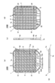
- FIG. 2A is an enlarged view of a D portion in FIG. 1A
- FIG. 2B is an enlarged view of an E portion in FIG.
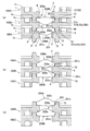
- A) is an optical product storage structure in a stacked state in which optical products are stored in a tray and stacked in multiple stages, and is an arrow view when cut along the cutting line FF in FIG.
- a sectional view is an inverted state obtained by vertically inverting the stacked state of FIG. 3 (a), and (c) is a state where the uppermost tray is removed from the inverted state of FIG.
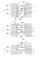
- (A) is an optical product storage structure in a stacked state in which optical products are stored in a tray and stacked in multiple stages, and is an arrow view when cut along the cutting line GG in FIG. A sectional view
- (b) is an inverted state obtained by vertically inverting the stacked state of FIG. 4 (a)
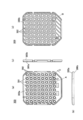
- (c) is a state where the uppermost tray is removed from the inverted state of FIG. 4 (b). It is the figure which showed the tray of the prior art example, (a) is a top view, (b) is a front view, (c) is a right view, (d) is a bottom view.
- (A) is an enlarged view of a portion A in FIG.
- FIG. 5A shows a conventional optical product housing structure in a stacked state in which optical products are housed in a tray and stacked in multiple stages, along a cutting line CC in FIG. 7B is a cross-sectional view taken along the arrow, FIG. 7B is an inverted state obtained by vertically inverting the stacked state of FIG. 7A, and FIG. 7C is an uppermost tray removed from the inverted state of FIG. It is in the state.
- FIG. 1 is a view showing a tray according to the present invention, where (a) is a top view, (b) is a front view, (c) is a right side view, (d) is a bottom view, and FIG. 2 (a).
- FIG. 2 is an enlarged view of a D portion in FIG. 1A
- FIG. 2B is an enlarged view of an E portion in FIG.
- FIG. 3A shows an optical product housing structure in a stacked state in which optical products are housed in a tray and stacked in multiple stages, and is cut along the cutting line FF in FIG. 3B is a cross-sectional view taken along the arrow, FIG. 3B is an inverted state obtained by vertically inverting the stacked state of FIG. 3A, and FIG. 3C is an uppermost tray from the inverted state of FIG. 3B. It shows the state that has been removed.
- FIG. 4 shows the optical product housing structure in a stacked state in which optical products are housed in a tray and stacked in multiple stages in the same manner as in FIG. 3, but the cutting line GG in FIG. It is a case where it cut
- the trays 100A, 100B, and 100C can accommodate the optical products 200A and 200B and can be stacked in multiple stages. Since all of the trays 100A, 100B, and 100C are the same, in the following description, only the tray 100B that houses the optical product 200B will be described.
- the tray 100B includes a plate-like tray body 1.
- the tray body 1 is preferably made of resin from the viewpoints of light weight and low cost, which hardly damage the optical product 200B. It may be made of metal.
- the tray main body 1 is formed with a plurality of circular recesses 2 in a plan view that are recessed from the upper surface 1a toward the lower surface 1b.
- a through-hole 4 having a circular shape in a plan view is formed through the lower surface and in which the lower optical surface 202b of the optical product 200B is disposed.
- the diameter of the through-hole 4 is designed so that the arranged optical surfaces 202a and 202b do not interfere with the wall surface forming the through-hole 4, and the scratches and dirt on the optical surfaces 202a and 202b are prevented.
- a mounting portion 3 on which the flange portion 201 of the optical product 200B is mounted is provided around the through hole 4 in the recess 2.
- the mounting portion 3 rises from the bottom surface of the recess 2 and is formed in a ring shape in plan view.
- the inner wall surface forming the recess 2 is inclined so that the diameter of the recess 2 increases upward. This gradient is set to about 0.75 °.
- the outer peripheral surface 201c of the flange portion 201 forms the recess 2. It is held in contact with the inner wall surface, specifically the root portion (outer peripheral holding portion 71). Thereby, the outer periphery of the optical product 200A is positioned, and the movement in the horizontal direction is restricted.
- the upper edge of the inner wall surface that forms the recess 2 is chamfered.
- groove portions 51a, 51b, 52a, 52b are formed at equal intervals on the outer periphery of the placement portion 3.
- two groove portions 51a, 51b facing each other are formed by notching the placement portion 3.
- at least one of the four groove portions 51a, 51b, 52a, and 52b is formed in the groove portions 51a, 51b, 52a, and 52b formed in the through holes 4 adjacent to each other in plan view.
- Such groove portions 51a, 51b, 52a, and 52b are used as tweezer holes for inserting and removing the optical product 200B, as well as a protrusion 6 described later.
- the structure can be simplified by using the grooves 51a, 51b, 52a, 52b also as the holes for tweezers.
- protrusions 6 are formed around the through hole 4 on the lower surface 1b of the tray body 1 so as to fall from the lower surface 1b. These protrusions 6 are provided at equal intervals around the through hole 4 and have a pin shape. The protrusions 6 are inserted into the grooves 51a, 51b, 52a, 52b of the lower tray 100A on which the tray body 1 is stacked (see FIG. 3A).
- the projection 6 is formed to be inclined so as to taper downward, and the tip thereof is chamfered.
- the gradient of the inner wall surface 72 of the protrusion 6 is about 3 °, which is larger than the gradient of the inner wall surface of the recess 2 described above.
- the inner wall surface 72 of the protrusion 6 holds the outer peripheral surface 201c of the flange portion 201 of the optical product 200A accommodated in the lower tray 100A when inverted (as will be described later) ( (Refer FIG.3 (b)). That is, in the state where the optical product 200A is accommodated and inverted, the inner wall surfaces 72 of the four protrusions 6 (specifically, the inscribed circle of the root portion of the inner wall surface 72 of the four protrusions 6) of the optical product 200A. The outer periphery is positioned and the movement of the flange portion 201 in the horizontal direction is restricted.
- the outer peripheral edge of the through hole 4 (between the through hole 4 and the protrusion 6) on the lower surface 1b of the tray body 1 is an optical product 200A accommodated in a lower tray 100A on which the tray body 1 is stacked in the stacked state.
- the flange portion 201 is pressed from above and serves as a pressing portion 8 for preventing the lifting.
- the outer peripheral edge 9 is stepped so as to be lower than the above-described upper surface 1a in which the recess 2 is formed. And in the lamination
- the outer peripheral edge 9 of the tray body 1 is formed with a notch 91 at a position facing each other so as to cut out the outer peripheral edge 9. Then, by hanging the rubber bands (not shown) on the notch portions 91 facing each other, the posture of the tray 100 at the time of stacking can be stabilized, and the shift and protrusion of the rubber bands can be prevented.
- the tray body 1 is formed with positioning holes 92 for positioning the tray body 1 with respect to another device (not shown).
- the flange portion 201 of the optical product 200 ⁇ / b> A is placed on the placement portion 3 of the lower tray 100 ⁇ / b> A, and the lower optical surface is placed in the through hole 4. 202b is arranged. At this time, the outer peripheral surface 201c of the flange portion 201 is held by the outer peripheral holding portion 71 of the concave portion 2, and the movement in the horizontal direction is restricted (see FIG. 4A).
- the optical surface 202b having a large convex portion is disposed so as to face the lower surface
- the optical surface 202a having a small convex portion is disposed so as to face the upper surface.
- the optical surface 202a having a small convex portion is arranged on the upper surface side, thereby preventing damage or the like of the optical surface 202a.
- the protruding portion 6 of the middle tray 100B is inserted into the grooves 51a, 51b, 52a, 52b of the lower tray 100A, whereby the flange portion 201 is pressed from above by the pressing portion 8 of the middle tray 100B and stacked.
- the upper surface 201a of the flange portion 201 of the optical product 200 is located below the upper surface 1a of the tray body 1 of the lower tray 100A, and does not protrude upward (in FIG. 3A).
- the alternate long and short dash line indicates the height position of the upper surface 1a of the tray body 1).
- the optical product 200B is similarly placed at a predetermined position on the middle tray 100B, and the upper tray 100C is stacked on the middle tray 100B to accommodate the optical products 200A and 200B.
- the stacked trays 100A, 100B, and 100C are fixed by putting bands on the notch portions 91 facing each other.
- the flange portions 201 of the optical products 200A and 200B in the inverted state are respectively pressed by the tray 100B.
- the outer peripheral surface 201c of the flange portion 201 is held by the inner wall surface 72 of the protruding portion 6 of the tray 100B (see FIG. 3B) while being placed on the portion 8 and the pressing portion 8 of the tray 100C.
- FIGS. 3 (c) and 4 (c) show a case where the tray 100A in the upper stage is removed from the inverted state of FIGS. 3 (b) and 4 (b).
- the flange portion 201 of the optical product 200A is placed on the pressing portion 8 of the tray 100B. Since the outer peripheral surface 201c of the flange part 201 is held by the inner wall surface 72 of the projection part 6 of the tray 100B (see FIG. 3C), operations such as inspection of the optical product 200B can be performed in this state. .
- the removed tray 100A is stacked on the tray 100B and returned, and then turned upside down, it can be easily returned to the initial stacked state (the state shown in FIGS. 3A and 4A). .
- the optical product 200A is accommodated in the tray body 1 of the lower tray 100A, and the tray of the lower tray 100A is stacked in the stacked state in which the middle tray 100B is stacked on the tray body 1.
- the flange portion 201 is placed on the placement portion 3 of the main body 1, the outer peripheral surface 201 c of the flange portion 201 is held by the outer peripheral holding portion 71 of the recess 2, and the lower optical surface 202 b is arranged in the through hole 4.
- the protrusion 6 of the middle tray 100B is inserted into the grooves 51a, 51b, 52a, 52b of the lower tray 100A, whereby the flange portion 201 is pressed from above by the pressing portion 8 of the middle tray 100C.
- the upper and lower surfaces and the outer peripheral surface 201c of the flange portion 201 of the optical product 200A are held.
- the upper and lower surfaces and the outer peripheral surface 201c of the flange portion 201 of the optical product 200B housed in the middle tray 100B are held by the upper tray 100C.
- optical products 200A and 200B can be reliably accommodated without being restricted from moving out.
- the optical surface 202b is disposed in the through holes 4 of the trays 100A and 100B, the optical products 200A and 200B can be observed as they are.
- the flange portion 201 of the optical product 200A that has become the upper stage due to the inversion is placed on the pressing portion 8 of the tray 100B, and the tray 100A that has become the upper stage due to the inversion is placed.
- the outer peripheral surface 201c of the flange portion 201 is held by the inner wall surface 72 of the protruding portion 6 of the tray 100B.
- the flange portion 201 of the optical product 200A is placed on the pressing portion 8 of the middle tray 100B, and the outer peripheral surface 201c is the inner wall surface 72 of the protruding portion 6. Since the optical surface 202a is disposed in the through hole 4, the operation such as observation of the optical product 200A can be performed as it is.
- the tray can be placed in the stacked state and the inverted state. Reversibility can be achieved, and convenience can be improved.
- the recess 2 for accommodating the optical products 200A and 200B is formed so as to be recessed from the upper surface 1a of the tray body 1 toward the lower surface 1b side, and is a digging type. The pins protruding from the pins will not break.
- the optical products 200A and 200B can be accommodated in such a manner as to enter the recess 2, so that the optical product 200B can be prevented from popping out.
- a tray lid that does not have a through hole may be provided at the uppermost and lowermost stages.
- a tray that does not contain optical products may be substituted.
- the protrusion 6 and the groove portions 51a, 51b, 52a, and 52b are provided, respectively, but at least three or more may be provided.
Landscapes
- Engineering & Computer Science (AREA)
- Mechanical Engineering (AREA)
- Packaging Frangible Articles (AREA)
- Stackable Containers (AREA)
Abstract
Description
板状のトレー本体を備え、
前記トレー本体には、
当該トレー本体の上面から下面側に向けて窪み、前記光学製品が収容される凹部と、
前記凹部内の上下面を貫通し、前記光学製品の光学面が配置される貫通孔と、
前記凹部内で前記貫通孔の周囲に形成されて、前記光学製品のフランジ部が載置される載置部と、
前記凹部を形成する内壁面に形成されて、前記光学製品の前記フランジ部の外周面が保持される外周保持部と、
前記トレー本体の下面のうち前記貫通孔の周囲で、前記下面から立ち下がる少なくとも3つ以上の突起部と、
前記トレー本体の前記載置部の外周で前記突起部に対応する位置に形成されて、当該トレー本体の上段に積層された上段のトレーの前記突起部が挿入される溝部と、
前記トレー本体の下面のうち前記貫通孔の周囲に形成されて、当該トレー本体の下段に積層された下段のトレーに収容した前記光学製品の前記フランジ部を上方から押さえる押さえ部と、が設けられていることを特徴とするトレーが提供される。
前記トレーは、板状のトレー本体を備え、
前記トレー本体には、
当該トレー本体の上面から下面側に向けて窪み、前記光学製品が収容される凹部と、
前記凹部内の上下面を貫通し、前記光学製品の光学面が配置される貫通孔と、
前記凹部内で前記貫通孔の周囲に形成されて、前記光学製品のフランジ部が載置される載置部と、
前記凹部を形成する内壁面に形成されて、前記光学製品の前記フランジ部の外周面が保持される外周保持部と、
前記トレー本体の下面のうち前記貫通孔の周囲で、前記下面から立ち下がる少なくとも3つ以上の突起部と、
前記トレー本体の前記載置部の外周で前記突起部に対応する位置に形成されて、当該トレー本体の上段に積層された上段のトレーの前記突起部が挿入される溝部と、
前記トレー本体の下面のうち前記貫通孔の周囲に形成されて、当該トレー本体の下段に積層された下段のトレーに収容した前記光学製品の前記フランジ部を上方から押さえる押さえ部と、が設けられており、
前記トレー本体に前記光学製品を収容し、当該トレー本体に対して上段のトレーを積層した積層状態では、前記フランジ部が前記トレー本体の前記載置部に載置されて、前記フランジ部の外周面が前記外周保持部によって保持されるとともに、前記光学面が前記貫通孔に配置され、
上段のトレーの前記突起部が前記溝部内に挿入されることによって、前記フランジ部が上段のトレーの前記押さえ部によって上方から押さえられることを特徴とする光学製品の収容構造が提供される。
前記トレーは、板状のトレー本体を備え、
前記トレー本体には、当該トレー本体の上面から下面側に向けて窪み、前記光学製品が収容される凹部と、
前記凹部内の上下面を貫通し、前記光学製品の光学面が配置される貫通孔と、
前記凹部内で前記貫通孔の周囲に形成されて、前記光学製品のフランジ部が載置される載置部と、
前記凹部を形成する内壁面に形成されて、前記光学製品の前記フランジ部の外周面が保持される外周保持部と、
前記トレー本体の下面のうち前記貫通孔の周囲で、前記下面から立ち下がる少なくとも3つ以上の突起部と、
前記トレー本体の前記載置部の外周で前記突起部に対応する位置に形成されて、当該トレー本体の上段に積層された上段のトレーの前記突起部が挿入される溝部と、
前記トレー本体の下面のうち前記貫通孔の周囲に形成されて、当該トレー本体の下段に積層された下段のトレーに収容した前記光学製品の前記フランジ部を上方から押さえる押さえ部と、が設けられており、
まず、前記トレー本体の前記載置部に前記光学製品のフランジ部を載置させて、前記フランジ部の外周面を前記外周保持部によって保持するとともに、前記光学面を前記貫通孔に配置し、
次いで、上段のトレーの前記突起部を前記トレー本体の前記溝部内に挿入させることによって、前記フランジ部を上段のトレーの前記押さえ部によって上方から押さえて、積層状態とすることを特徴とする光学製品の収容方法が提供される。
1a 上面
1b 下面
2 凹部
3 載置部
4 貫通孔
51a,51b,52a,52b 溝部
6 突起部
71 外周保持部
72 内壁面
8 押さえ部
100A、100B,100C トレー
200A,200B 光学製品
201 フランジ部
201c 外周面
202a,202b 光学面
Claims (7)
- 光学製品を収容して多段に積層可能なトレーであって、
板状のトレー本体を備え、
前記トレー本体には、
当該トレー本体の上面から下面側に向けて窪み、前記光学製品が収容される凹部と、
前記凹部内の上下面を貫通し、前記光学製品の光学面が配置される貫通孔と、
前記凹部内で前記貫通孔の周囲に形成されて、前記光学製品のフランジ部が載置される載置部と、
前記凹部を形成する内壁面に形成されて、前記光学製品の前記フランジ部の外周面が保持される外周保持部と、
前記トレー本体の下面のうち前記貫通孔の周囲で、前記下面から立ち下がる少なくとも3つ以上の突起部と、
前記トレー本体の前記載置部の外周で前記突起部に対応する位置に形成されて、当該トレー本体の上段に積層された上段のトレーの前記突起部が挿入される溝部と、
前記トレー本体の下面のうち前記貫通孔の周囲に形成されて、当該トレー本体の下段に積層された下段のトレーに収容した前記光学製品の前記フランジ部を上方から押さえる押さえ部と、が設けられていることを特徴とするトレー。 - 光学製品をトレーに収容して、当該トレーを多段に積層した光学製品の収容構造であって、
前記トレーは、板状のトレー本体を備え、
前記トレー本体には、
当該トレー本体の上面から下面側に向けて窪み、前記光学製品が収容される凹部と、
前記凹部内の上下面を貫通し、前記光学製品の光学面が配置される貫通孔と、
前記凹部内で前記貫通孔の周囲に形成されて、前記光学製品のフランジ部が載置される載置部と、
前記凹部を形成する内壁面に形成されて、前記光学製品の前記フランジ部の外周面が保持される外周保持部と、
前記トレー本体の下面のうち前記貫通孔の周囲で、前記下面から立ち下がる少なくとも3つ以上の突起部と、
前記トレー本体の前記載置部の外周で前記突起部に対応する位置に形成されて、当該トレー本体の上段に積層された上段のトレーの前記突起部が挿入される溝部と、
前記トレー本体の下面のうち前記貫通孔の周囲に形成されて、当該トレー本体の下段に積層された下段のトレーに収容した前記光学製品の前記フランジ部を上方から押さえる押さえ部と、が設けられており、
前記トレー本体に前記光学製品を収容し、当該トレー本体に対して上段のトレーを積層した積層状態では、前記フランジ部が前記トレー本体の前記載置部に載置されて、前記フランジ部の外周面が前記外周保持部によって保持されるとともに、前記光学面が前記貫通孔に配置され、
上段のトレーの前記突起部が前記溝部内に挿入されることによって、前記フランジ部が上段のトレーの前記押さえ部によって上方から押さえられることを特徴とする光学製品の収容構造。 - 前記積層状態から上下反転させた状態では、
前記積層状態で上段にあったトレーの前記押さえ部に前記フランジ部が載置され、前記貫通孔に光学面が配置されるとともに、
前記上段にあったトレーの前記突起部が、前記トレー本体の前記溝部内に挿入され、前記フランジ部が前記トレー本体の前記載置部によって上方から押さえられるとともに、前記フランジ部の外周面が前記上段にあったトレーの前記突起部の内壁面によって保持されることを特徴とする請求項2に記載の光学製品の収容構造。 - 前記積層状態において、前記トレー本体の上面は、当該トレー本体に収容した前記光学製品の前記フランジ部の上面よりも突出していることを特徴とする請求項2又は請求項3に記載の光学製品の収容構造。
- 前記積層状態において、前記光学製品の両面の光学面のうち、凸部の大きい光学面側が下面を向くように前記光学製品が配置されていることを特徴とする請求項2~4の何れか1項に記載の光学製品の収容構造。
- 光学製品をトレーに収容し、当該トレーを多段に積層する光学製品の収容方法であって、
前記トレーは、板状のトレー本体を備え、
前記トレー本体には、当該トレー本体の上面から下面側に向けて窪み、前記光学製品が収容される凹部と、
前記凹部内の上下面を貫通し、前記光学製品の光学面が配置される貫通孔と、
前記凹部内で前記貫通孔の周囲に形成されて、前記光学製品のフランジ部が載置される載置部と、
前記凹部を形成する内壁面に形成されて、前記光学製品の前記フランジ部の外周面が保持される外周保持部と、
前記トレー本体の下面のうち前記貫通孔の周囲で、前記下面から立ち下がる少なくとも3つ以上の突起部と、
前記トレー本体の前記載置部の外周で前記突起部に対応する位置に形成されて、当該トレー本体の上段に積層された上段のトレーの前記突起部が挿入される溝部と、
前記トレー本体の下面のうち前記貫通孔の周囲に形成されて、当該トレー本体の下段に積層された下段のトレーに収容した前記光学製品の前記フランジ部を上方から押さえる押さえ部と、が設けられており、
まず、前記トレー本体の前記載置部に前記光学製品のフランジ部を載置させて、前記フランジ部の外周面を前記外周保持部によって保持するとともに、前記光学面を前記貫通孔に配置し、
次いで、上段のトレーの前記突起部を前記トレー本体の前記溝部内に挿入させることによって、前記フランジ部を上段のトレーの前記押さえ部によって上方から押さえて、積層状態とすることを特徴とする光学製品の収容方法。 - 前記積層状態から上下反転させることによって、
前記積層状態で前記上段にあったトレーの前記押さえ部に前記フランジ部を載置させて、前記貫通孔に光学面を配置させるとともに、
前記上段にあったトレーの前記突起部を、前記トレー本体の前記溝部内に挿入させ、前記フランジ部を前記トレー本体の前記載置部によって上方から押さえるとともに、前記フランジ部の外周面を前記上段にあったトレーの前記突起部の内壁面によって保持させることを特徴とする請求項6に記載の光学製品の収容方法。
Priority Applications (2)
| Application Number | Priority Date | Filing Date | Title |
|---|---|---|---|
| CN2011800163056A CN102933470A (zh) | 2010-03-31 | 2011-02-22 | 托盘、光学产品的收容构造以及光学产品的收容方法 |
| JP2012508142A JPWO2011122173A1 (ja) | 2010-03-31 | 2011-02-22 | トレー、光学製品の収容構造及び光学製品の収容方法 |
Applications Claiming Priority (2)
| Application Number | Priority Date | Filing Date | Title |
|---|---|---|---|
| JP2010-080804 | 2010-03-31 | ||
| JP2010080804 | 2010-03-31 |
Publications (1)
| Publication Number | Publication Date |
|---|---|
| WO2011122173A1 true WO2011122173A1 (ja) | 2011-10-06 |
Family
ID=44711905
Family Applications (1)
| Application Number | Title | Priority Date | Filing Date |
|---|---|---|---|
| PCT/JP2011/053804 Ceased WO2011122173A1 (ja) | 2010-03-31 | 2011-02-22 | トレー、光学製品の収容構造及び光学製品の収容方法 |
Country Status (3)
| Country | Link |
|---|---|
| JP (1) | JPWO2011122173A1 (ja) |
| CN (1) | CN102933470A (ja) |
| WO (1) | WO2011122173A1 (ja) |
Citations (2)
| Publication number | Priority date | Publication date | Assignee | Title |
|---|---|---|---|---|
| JP2001348080A (ja) * | 2000-04-04 | 2001-12-18 | Nissin Kohki Co Ltd | 製品収納容器 |
| JP2007161278A (ja) * | 2005-12-12 | 2007-06-28 | Matsushita Electric Ind Co Ltd | パレットとこれを用いた光学部品の製造方法および光学部品の包装体と収容体 |
Family Cites Families (2)
| Publication number | Priority date | Publication date | Assignee | Title |
|---|---|---|---|---|
| JP4617247B2 (ja) * | 2005-11-29 | 2011-01-19 | 日立マクセル株式会社 | トレイ |
| CN101445168B (zh) * | 2007-11-26 | 2011-05-04 | 鸿富锦精密工业(深圳)有限公司 | 托盘 |
-
2011
- 2011-02-22 WO PCT/JP2011/053804 patent/WO2011122173A1/ja not_active Ceased
- 2011-02-22 CN CN2011800163056A patent/CN102933470A/zh active Pending
- 2011-02-22 JP JP2012508142A patent/JPWO2011122173A1/ja active Pending
Patent Citations (2)
| Publication number | Priority date | Publication date | Assignee | Title |
|---|---|---|---|---|
| JP2001348080A (ja) * | 2000-04-04 | 2001-12-18 | Nissin Kohki Co Ltd | 製品収納容器 |
| JP2007161278A (ja) * | 2005-12-12 | 2007-06-28 | Matsushita Electric Ind Co Ltd | パレットとこれを用いた光学部品の製造方法および光学部品の包装体と収容体 |
Also Published As
| Publication number | Publication date |
|---|---|
| CN102933470A (zh) | 2013-02-13 |
| JPWO2011122173A1 (ja) | 2013-07-08 |
Similar Documents
| Publication | Publication Date | Title |
|---|---|---|
| CN102320406B (zh) | 一种托盘组合 | |
| JP2011513978A (ja) | 太陽電池ウェハを搬送するためのウェハボックス | |
| JP2013163533A (ja) | トレーを用いた光学部品の製造方法 | |
| WO2011122173A1 (ja) | トレー、光学製品の収容構造及び光学製品の収容方法 | |
| JP4941527B2 (ja) | 半導体チップ収容トレイ | |
| KR101632828B1 (ko) | 반도체 칩 트레이 | |
| JP2009202883A (ja) | レンズユニット収納用トレイ | |
| JP4811008B2 (ja) | パレットとこれを用いた光学部品の製造方法および光学部品の包装体と収容体 | |
| JP4617247B2 (ja) | トレイ | |
| JP4630925B2 (ja) | 収納トレー及び収納体 | |
| JP2006143246A (ja) | 収納用治具およびそれを用いた半導体製造方法 | |
| KR101699603B1 (ko) | 반도체 칩 트레이 | |
| JP5717505B2 (ja) | ウエハ収納容器 | |
| KR100826135B1 (ko) | 상하 적층수단을 갖는 트레이 | |
| KR102603102B1 (ko) | 표시 패널용 트레이 및 트레이 집합체 | |
| JP2011116415A (ja) | 容器、包装体及びレンズ包装品 | |
| JP2010269853A (ja) | 収納トレー及び収納体 | |
| JP5609548B2 (ja) | 半導体チップトレイ及び半導体チップの搬送方法 | |
| CN216035656U (zh) | 托盘及托盘组合 | |
| CN216035655U (zh) | 托盘及托盘组合 | |
| JP2005263254A (ja) | ムーブメントトレー | |
| JP2013151313A (ja) | 収容容器 | |
| JP5678494B2 (ja) | 電子デバイス用収納容器 | |
| CN217146745U (zh) | Tray盘 | |
| JPWO2009060680A1 (ja) | 光学製品収容容器及び光学製品収容方法 |
Legal Events
| Date | Code | Title | Description |
|---|---|---|---|
| WWE | Wipo information: entry into national phase |
Ref document number: 201180016305.6 Country of ref document: CN |
|
| 121 | Ep: the epo has been informed by wipo that ep was designated in this application |
Ref document number: 11762413 Country of ref document: EP Kind code of ref document: A1 |
|
| WWE | Wipo information: entry into national phase |
Ref document number: 2012508142 Country of ref document: JP |
|
| NENP | Non-entry into the national phase |
Ref country code: DE |
|
| 122 | Ep: pct application non-entry in european phase |
Ref document number: 11762413 Country of ref document: EP Kind code of ref document: A1 |