WO2011122089A1 - 表示装置及び、表示装置のプログラム - Google Patents
表示装置及び、表示装置のプログラム Download PDFInfo
- Publication number
- WO2011122089A1 WO2011122089A1 PCT/JP2011/051728 JP2011051728W WO2011122089A1 WO 2011122089 A1 WO2011122089 A1 WO 2011122089A1 JP 2011051728 W JP2011051728 W JP 2011051728W WO 2011122089 A1 WO2011122089 A1 WO 2011122089A1
- Authority
- WO
- WIPO (PCT)
- Prior art keywords
- color
- waveform
- rewriting
- rewrite
- rewrite instruction
- Prior art date
- Legal status (The legal status is an assumption and is not a legal conclusion. Google has not performed a legal analysis and makes no representation as to the accuracy of the status listed.)
- Ceased
Links
Images







Classifications
-
- G—PHYSICS
- G09—EDUCATION; CRYPTOGRAPHY; DISPLAY; ADVERTISING; SEALS
- G09G—ARRANGEMENTS OR CIRCUITS FOR CONTROL OF INDICATING DEVICES USING STATIC MEANS TO PRESENT VARIABLE INFORMATION
- G09G3/00—Control arrangements or circuits, of interest only in connection with visual indicators other than cathode-ray tubes
- G09G3/20—Control arrangements or circuits, of interest only in connection with visual indicators other than cathode-ray tubes for presentation of an assembly of a number of characters, e.g. a page, by composing the assembly by combination of individual elements arranged in a matrix no fixed position being assigned to or needed to be assigned to the individual characters or partial characters
- G09G3/2007—Display of intermediate tones
-
- G—PHYSICS
- G09—EDUCATION; CRYPTOGRAPHY; DISPLAY; ADVERTISING; SEALS
- G09G—ARRANGEMENTS OR CIRCUITS FOR CONTROL OF INDICATING DEVICES USING STATIC MEANS TO PRESENT VARIABLE INFORMATION
- G09G3/00—Control arrangements or circuits, of interest only in connection with visual indicators other than cathode-ray tubes
- G09G3/20—Control arrangements or circuits, of interest only in connection with visual indicators other than cathode-ray tubes for presentation of an assembly of a number of characters, e.g. a page, by composing the assembly by combination of individual elements arranged in a matrix no fixed position being assigned to or needed to be assigned to the individual characters or partial characters
- G09G3/34—Control arrangements or circuits, of interest only in connection with visual indicators other than cathode-ray tubes for presentation of an assembly of a number of characters, e.g. a page, by composing the assembly by combination of individual elements arranged in a matrix no fixed position being assigned to or needed to be assigned to the individual characters or partial characters by control of light from an independent source
- G09G3/3433—Control arrangements or circuits, of interest only in connection with visual indicators other than cathode-ray tubes for presentation of an assembly of a number of characters, e.g. a page, by composing the assembly by combination of individual elements arranged in a matrix no fixed position being assigned to or needed to be assigned to the individual characters or partial characters by control of light from an independent source using light modulating elements actuated by an electric field and being other than liquid crystal devices and electrochromic devices
- G09G3/344—Control arrangements or circuits, of interest only in connection with visual indicators other than cathode-ray tubes for presentation of an assembly of a number of characters, e.g. a page, by composing the assembly by combination of individual elements arranged in a matrix no fixed position being assigned to or needed to be assigned to the individual characters or partial characters by control of light from an independent source using light modulating elements actuated by an electric field and being other than liquid crystal devices and electrochromic devices based on particles moving in a fluid or in a gas, e.g. electrophoretic devices
-
- G—PHYSICS
- G09—EDUCATION; CRYPTOGRAPHY; DISPLAY; ADVERTISING; SEALS
- G09G—ARRANGEMENTS OR CIRCUITS FOR CONTROL OF INDICATING DEVICES USING STATIC MEANS TO PRESENT VARIABLE INFORMATION
- G09G2320/00—Control of display operating conditions
- G09G2320/02—Improving the quality of display appearance
- G09G2320/0242—Compensation of deficiencies in the appearance of colours
-
- G—PHYSICS
- G09—EDUCATION; CRYPTOGRAPHY; DISPLAY; ADVERTISING; SEALS
- G09G—ARRANGEMENTS OR CIRCUITS FOR CONTROL OF INDICATING DEVICES USING STATIC MEANS TO PRESENT VARIABLE INFORMATION
- G09G2320/00—Control of display operating conditions
- G09G2320/02—Improving the quality of display appearance
- G09G2320/0247—Flicker reduction other than flicker reduction circuits used for single beam cathode-ray tubes
-
- G—PHYSICS
- G09—EDUCATION; CRYPTOGRAPHY; DISPLAY; ADVERTISING; SEALS
- G09G—ARRANGEMENTS OR CIRCUITS FOR CONTROL OF INDICATING DEVICES USING STATIC MEANS TO PRESENT VARIABLE INFORMATION
- G09G2320/00—Control of display operating conditions
- G09G2320/02—Improving the quality of display appearance
- G09G2320/0261—Improving the quality of display appearance in the context of movement of objects on the screen or movement of the observer relative to the screen
Definitions
- the present invention relates to a display device that rewrites an image according to a user operation and a program for the display device.
- the image displayed on the display device using the electrophoretic display is rewritten when an input button provided on the display device is pressed.
- the display device applies a positive voltage or a negative voltage to the electrodes, and rewrites the image displayed on the electrophoretic display.
- the display device may perform a process of reversing the direction of the electric field between the electrodes for a certain period of time in order to remove the afterimage on the screen. is there. Thereby, the moving direction of the particles may be reversed.
- the direction in which the direction of the electric field is reversed in the middle is long, the color displayed on the electrophoretic display flickers due to a change in the distribution state of the white charged particles and the black charged particles between the electrodes. For example, when the display is rewritten from white to gray, a dark gray closer to black than gray is displayed once and then rewritten to gray.
- the brightness decreases until white to dark gray is displayed, and the brightness increases until dark gray to gray is displayed.
- the display appears to flicker depending on the brightness level. It is conceivable that the user continuously presses the input button in order to rewrite the display. If the display is continuously rewritten, the color flickers continuously, so the display looks particularly flickering.
- the present invention has been made to solve the above-described problems, and provides a display device capable of suppressing flickering of color due to a change in the distribution state of charged particles between electrodes in display rewriting, and a program for the display device The purpose is to do.
- the present invention described in claim 1 has a first color, a positively charged first charged particle, and a second color between a pair of opposed electrodes.
- the negatively charged second charged particles are arranged, and the voltage is applied between the two electrodes, whereby the arrangement of the first charged particles and the second charged particles changes, and the first color
- a display unit capable of displaying any one of a color and a third color which is a mixed color of the first color and the second color, and the display unit from a color before rewriting to a color after rewriting
- the second rewriting process in which the color of the display unit is rewritten from the color before rewriting to the same color after rewriting from the color before rewriting to the color after rewriting
- the waveform determining unit displays on the display unit if the rewriting instruction next to the rewriting instruction read by the rewriting instruction reading unit is stored in the rewriting instruction storage unit. It is determined that the waveform for rewriting the color is the second waveform, and if the rewrite instruction next to the rewrite instruction read by the rewrite instruction reading unit is not stored in the rewrite instruction storage unit, The waveform for rewriting the color displayed on the display unit is determined to be the first waveform.
- the waveform storage unit is configured such that the first change curve is set to have an extreme value.
- One waveform and the second waveform determined so that the second change curve does not have the extreme value are stored.
- the waveform storage unit is configured such that the first change curve has a maximum value and a minimum value.
- the difference between the maximum value and the minimum value is a first inversion amount
- the first change curve has one extreme value
- the extreme value and the color before rewriting And storing the first waveform determined so that one of the absolute value of the difference between the absolute value and the absolute value of the difference between the extreme value and the color after rewriting is the first inversion amount.
- the first inversion amount is larger than an inversion recognition amount that is a change amount of a color recognized as an inversion of a color displayed on the display unit.
- the waveform storage unit is configured such that the first change curve has a first maximum value and a first minimum value. Storing the first waveform determined to have and the second waveform determined so that the second change curve has a second maximum value and a second minimum value, and storing the second maximum The third inversion amount, which is the difference between the value and the second minimum value, is smaller than the second inversion amount, which is the difference between the first maximum value and the first minimum value.
- the present invention according to claim 5 is the display device according to claim 4, wherein the waveform storage unit inverts the second inversion amount and the color displayed on the display unit.
- the first change curve determined to be the first change curve larger than the reversal recognition amount recognized as having been made, and the third change amount being the second change curve smaller than the reversal recognition amount. And storing the second waveform defined in (1).
- the color before rewriting and the color after rewriting are changed from the first color to the first color. It is a color of discrete gradations up to the second color, and the interval between the adjacent gradations is larger than the inversion recognition amount.
- the present invention according to claim 7 is the display device according to claim 1, wherein the rewrite instruction determination unit determines whether the rewrite instruction is a next page rewrite or a previous page rewrite, and the rewrite instruction.
- the instruction determination unit determines that the rewrite instruction read by the rewrite instruction reading unit is the next page rewrite instruction, and the rewrite instruction next to the determined rewrite instruction is the previous page rewrite instruction.
- the rewrite instruction determining unit determines that the rewrite instruction read by the rewrite instruction reading unit is a previous page rewrite instruction, and the rewrite instruction next to the determined rewrite instruction is a next page.
- the rewrite unit rewrites the color displayed on the display unit according to the rewrite instruction read by the rewrite instruction reading unit when the rewrite instruction is determined to be a rewrite instruction. It is characterized in that it comprises a rewriting canceling unit, the halting and.
- the time during which the color is rewritten by the second waveform is longer than the time during which the color is rewritten by the first waveform. Is also short.
- the present invention has a first color, a first charged particle having a positive polarity, and a second color between a pair of opposed electrodes.
- the negatively charged second charged particles are arranged, and the voltage is applied between the two electrodes, whereby the arrangement of the first charged particles and the second charged particles changes, and the first color
- a display unit capable of displaying any one of a color and a third color which is a mixed color of the first color and the second color, and the display unit from a color before rewriting to a color after rewriting
- the first waveform defined so that the color change displayed on the display unit becomes a first change curve, and the same color before the rewriting as in the first rewriting process
- the second rewriting process in which the color of the display unit is rewritten from the color before rewriting to the same color after rewriting from the color before rewriting to the color after
- a rewrite instruction reading step for reading the rewrite instruction stored in the rewrite instruction storage unit on a computer of the display device, and whether the waveform for rewriting the color displayed on the display unit is the first waveform or the second waveform.
- the display unit according to the waveform determining step for determining the waveform, the first waveform or the second waveform determined by the waveform determining step, and the rewrite instruction read by the rewrite instruction reading step.
- the rewrite instruction next to the rewrite instruction is stored in the rewrite instruction storage unit, it is determined that the waveform for rewriting the color displayed on the display unit is the second waveform, and the rewrite instruction read If the rewrite instruction next to the rewrite instruction read in step is not stored in the rewrite instruction storage unit, it is determined that the waveform for rewriting the color displayed on the display unit is the first waveform. Is a program for a display device.
- the waveform determining unit is displayed on the display unit. It is determined that the waveform for rewriting the existing color is the second waveform. If the rewrite instruction next to the rewrite instruction read by the rewrite instruction reading unit is not stored in the rewrite instruction storage unit, the waveform determining unit determines that the waveform rewriting the color displayed on the display unit is the first waveform. to decide. The total length of the first change curve is longer than the total length of the second change curve.
- the position of the particles arranged between the pair of electrodes facing each other can be controlled in detail. Thereby, a display with little afterimage can be performed. Therefore, when the color displayed on the display unit is rewritten according to the first waveform, the afterimage of the color displayed on the display unit is erased.
- the total length of the second change curve is shorter than the total length of the first change curve. Therefore, when the color displayed on the display unit is rewritten according to the second waveform, the color flicker due to the change in the distribution state between the first charged particles and the electrodes of the second charged particles is colored by the first waveform. Is suppressed more than when rewritten.
- the rewriting unit When rewriting instructions are continuously input, the rewriting unit follows the rewriting instructions other than the rewriting instruction that is input last, and the second waveform that suppresses flickering of colors. Rewrite.
- the rewriting unit rewrites the color with the first waveform from which the afterimage is erased in accordance with the rewriting instruction input last among the rewriting instructions input continuously. Therefore, when the rewrite instruction is continuously input to the input unit, the number of times of rewriting the color can be reduced according to the first waveform. Thereby, the flicker of the color by the change of the distribution state between the electrode of the 1st charged particle and the 2nd charged particle can be suppressed.
- the color is rewritten by the first waveform determined so that the first change curve has an extreme value.
- the color is rewritten by the second waveform determined so that the second change curve does not have an extreme value. Therefore, when the color is rewritten according to the first waveform, the moving direction of the first charged particles and the moving direction of the second charged particles are reversed in the first rewriting process. Therefore, rewriting with the first waveform can erase afterimages better than when the color is rewritten with a waveform determined so that the change curve does not have an extreme value.
- the moving direction of the first charged particle and the moving direction of the second charged particle are determined in the second rewriting process. Do not invert. Therefore, the rewriting with the second waveform can reduce the color change in the second rewriting process, compared with the case where the color is rewritten according to the waveform determined so that the change curve has an extreme value. Thereby, the flicker of the color by the change of the distribution state between the electrode of the 1st charged particle and the 2nd charged particle can be suppressed.
- the color is rewritten according to the first waveform determined so that the first change curve has the first inversion amount larger than the inversion recognition amount. Therefore, when the first change curve has a maximum value and a minimum value, the time between the moving direction of the first charged particles and the moving direction of the second charged particles takes a maximum value and a time point at which the minimum value is taken. Reverse with. When the first change curve has one extreme value, the time when the moving direction of the first charged particle and the moving direction of the second charged particle take the extreme value before rewriting or when the extreme value takes the extreme value. Inverts between and after rewriting.
- the change curve Since the first reversal amount at the time when the moving direction of the first charged particles and the moving direction of the second charged particles are reversed is larger than the reversal recognition amount, the change curve has a reversal amount smaller than the reversal recognition amount.
- the rewriting with the first waveform can erase the afterimage more than the color is rewritten according to the determined waveform.
- the rewrite instruction is stored according to the waveform determined so that the third inversion amount is larger than the second inversion amount.
- the rewriting with the second waveform can suppress the flickering of the color due to the change in the distribution state between the first charged particles and the electrodes of the second charged particles, rather than the color being rewritten in a state where the color is changed.
- the second inversion amount is larger than the inversion recognition amount
- the third inversion amount is smaller than the inversion recognition amount. Therefore, rewriting with the first waveform can erase the afterimage more than when the color is rewritten according to the waveform determined so that the change curve has the second inversion amount smaller than the inversion recognition amount.
- the rewriting with the second waveform can suppress the color change in the second rewriting process, rather than rewriting the color with the waveform determined so that the change curve has the third inversion amount larger than the inversion recognition amount. Thereby, the flicker of the color by the change of the distribution state between the electrode of the 1st charged particle and the 2nd charged particle can be suppressed.
- the interval between the adjacent gradation colors is equal to or greater than the inversion recognition amount
- the interval between the adjacent gradation colors is set to be less than the inversion recognition amount.
- the rewrite instruction determination unit determines that the rewrite instruction read by the rewrite instruction reading unit is the next page rewrite instruction, and follows the rewrite instruction determined by the rewrite instruction determination unit. May be determined to be the previous page rewrite instruction.
- the rewrite instruction determining unit determines that the rewrite instruction read by the rewrite instruction reading unit is the previous page rewrite instruction, and determines that the rewrite instruction next to the rewrite instruction determined by the rewrite instruction determining unit is the previous page rewrite instruction. There is a case.
- the rewrite cancel unit causes the rewrite unit to stop rewriting the color displayed on the display unit in accordance with the rewrite instruction read by the rewrite instruction reading unit. Therefore, the number of times of rewriting the color with the second waveform can be reduced. Thereby, the flicker of the color by the change of the distribution state between the electrode of the 1st charged particle and the 2nd charged particle by this can be suppressed.
- the time for rewriting the color according to the second waveform is shorter than the time for rewriting the color according to the first waveform. Accordingly, it is possible to shorten the time until the rewritten color is displayed in accordance with the last rewriting instruction among the rewriting instructions continuously input to the input unit.
- the waveform determination step is displayed on the display unit if the rewrite instruction next to the rewrite instruction read by the rewrite instruction reading step is stored in the rewrite instruction storage unit. It is determined that the waveform for rewriting the existing color is the second waveform.
- the waveform determination step if the rewrite instruction next to the rewrite instruction read in the rewrite instruction reading step is not stored in the rewrite instruction storage unit, the waveform rewriting the color displayed on the display unit is the first waveform. to decide.
- the total length of the first change curve is longer than the total length of the second change curve.
- the position of the particles arranged between the pair of electrodes facing each other can be controlled in detail. Thereby, a display with little afterimage can be performed. Therefore, when the color displayed on the display unit is rewritten according to the first waveform, the afterimage of the color displayed on the display unit is erased.
- the total length of the second change curve is shorter than the total length of the first change curve. Therefore, when the color displayed on the display unit is rewritten according to the second waveform, the color flicker due to the change in the distribution state between the first charged particles and the electrodes of the second charged particles is colored by the first waveform. Is suppressed more than when rewritten.
- the rewriting unit When rewriting instructions are continuously input, the rewriting unit follows the rewriting instruction other than the rewriting instruction that is input last among the rewriting instructions that have been continuously input, and the second waveform that suppresses flickering of colors.
- Rewrite In the rewriting step, the color is rewritten with the first waveform in which the afterimage is erased in accordance with the rewriting instruction inputted last among the rewriting instructions inputted continuously. Therefore, when the rewrite instruction is continuously input to the input unit, the number of times of rewriting the color can be reduced according to the first waveform. Thereby, the flicker of the color by the change of the distribution state between the electrode of the 1st charged particle and the 2nd charged particle can be suppressed.
- FIG. 3 is a front view of the display device 1.
- FIG. 2 is a block diagram illustrating a hardware configuration of a display device 1.
- FIG. 3 is a diagram showing a configuration of a storage area of a ROM 33.
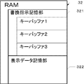
- FIG. 3 is a diagram illustrating a configuration of a storage area of a RAM 32.
- FIG. 3 is a diagram showing a configuration of a storage area of a memory card 41.
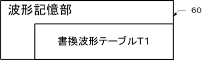
- FIG. 3 is a diagram showing a configuration of a storage area of a waveform storage unit 60.
- FIG. (A) It is a wave form diagram of the normal rewriting waveform which rewrites the color of the display part 10 from "white” to "white”.
- (B) It is a wave form diagram of the high-speed rewriting waveform which rewrites the color of the display part 10 from “white” to “white”.
- (C) It is a figure showing the change of the brightness of the color displayed on the display part 10 when the color of the display part 10 is rewritten from “white” to “white”.
- (A) It is a wave form diagram of the normal rewriting waveform which rewrites the color of the display part 10 from "white” to "black.”
- (B) It is a wave form diagram of the high-speed rewriting waveform which rewrites the color of the display part 10 from "white” to "black”.
- (C) It is a figure showing the change of the brightness of the color displayed on the display part 10 when the color of the display part 10 is rewritten from "white” to “black”.
- (A) It is a wave form diagram of the normal rewriting waveform which rewrites the color of the display part 10 from “white” to “light gray 4.”
- (B) A waveform diagram of a high-speed rewriting waveform for rewriting the color of the display unit 10 from “white” to “light gray 4”.
- (C) It is a figure showing the change of the brightness of the color displayed on the display part 10 when the color of the display part 10 is rewritten from "white” to "light gray 4".
- (A) It is a wave form diagram of the normal rewriting waveform which rewrites the color of the display part 10 from “white” to “dark gray 7.”
- (B) A waveform diagram of a high-speed rewrite waveform for rewriting the color of the display unit 10 from “white” to “light gray 7”.
- (C) It is a figure showing the change of the brightness of the color displayed on the display part 10 when the color of the display part 10 is rewritten from "white” to "dark gray 7.” * The figure should be divided into (A), (B), and (C), and each figure should be revised.
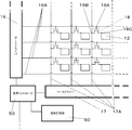
- 2 is a diagram illustrating a configuration of a display unit 10.
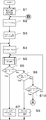
- 3 is a flowchart illustrating a procedure of overall processing of a control unit 30.
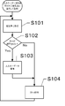
- 3 is a flowchart illustrating a procedure of an input key data acquisition task of a control unit 30.
- 3 is a flowchart illustrating a procedure of overall processing of a control unit 30.
- 3 is a flowchart illustrating a procedure of overall processing of a control unit 30.
- 3 is a flowchart illustrating a procedure of overall processing of a control unit 30.
- the display unit 10 is disposed in front of the display device 1.
- the display unit 10 is a known active matrix type electrophoretic display.
- the display unit 10 displays a page image that is an image including characters, symbols, and figures based on page image data described later.
- the display unit 10 can maintain the display state even when the power supply is cut off.
- the input unit 20 is arranged on the right side of the display unit 10.
- the input unit 20 includes a power key 21 that is pressed when the user gives an instruction to turn on or off the power, and a plurality of instructions for the user to input a predetermined instruction while the display device 1 is turned on. And an input key 22.
- the plurality of input keys 22 include a menu key 23, a close key 24, a previous key 25, a next key 26, 13 selection keys 27, and an enter key 28.
- the display device 1 rewrites the image according to the type of the pressed input key 22 and the image being displayed.
- the menu key 23 is a key that the user presses when displaying a menu screen.
- the close key 24 is a key that is pressed to close a page image (to be described later) being displayed.
- the previous key 25 is a key to be pressed when the page image being displayed is rewritten to the previous page image.
- the next key 26 is a key to be pressed when the page image being displayed is rewritten to the next page image.
- the selection key 27 is a key to be pressed when selecting a menu item being displayed on the menu screen.
- the determination key 28 is a key that is pressed when determining a document file to be described later.
- FIG. 2 is a schematic view of a cross section in the AA direction of FIG.
- the direction from the pixel electrode 12 toward the transparent electrode 14 is the upward direction.
- the direction from the transparent electrode 14 toward the pixel electrode 12 is the downward direction.
- the substrate 11 is disposed below the display unit 10.
- a plurality of pixel electrodes 12 are disposed on the substrate 11.
- Microcapsules 13 are respectively disposed on the pixel electrodes 12.
- a transparent electrode 14 is disposed on the microcapsule 13 so as to cover the microcapsule 13 provided in the display unit 10.
- a transparent substrate 15 is disposed on the transparent electrode 14.
- each pixel of the display unit 10 corresponds to each pixel electrode 12.
- the electrode pixel electrode 12 and the transparent electrode 14 are an example of a pair of electrodes facing each other in the present invention.
- the microcapsule 13 includes a plurality of white charged particles 13A, a plurality of black charged particles 13B, and a dispersion medium 13C.
- the white charged particles 13A have a negative polarity.
- the black charged particles 13B have a positive polarity.
- the white charged particles 13A, the black charged particles 13B, and the dispersion medium 13C have substantially the same specific gravity.
- the transparent electrode 14 is connected to a power source (not shown) and a predetermined voltage is applied. This voltage is, for example, 1 volt.
- a predetermined voltage is applied.
- This voltage is, for example, 1 volt.
- a positive voltage is applied to the pixel electrode 12
- the white charged particles 13A move to the pixel electrode 12 side
- the black charged particles 13B move to the transparent electrode 14 side. Accordingly, black is displayed on the transparent substrate 15 side of the display unit 10.
- a negative voltage is applied to the pixel electrode 12
- the black charged particles 13B move to the pixel electrode 12 side
- the white charged particles 13A move to the transparent electrode 14 side. Accordingly, white is displayed on the transparent substrate 15 side of the display unit 10.
- the color displayed on the display unit 10 varies depending on the distribution state of each charged particle in the microcapsule 13. Black and white are the first and second colors of the present invention, respectively.
- the halftone color is the third color of the present invention.
- the positive voltage is +50 volts, for example.
- the negative voltage is, for example, ⁇ 50 volts.
- the display device 1 includes a display unit 10, an input unit 20, a control unit 30, a memory card interface 40, a display controller 50, and a waveform storage unit 60.
- the memory card 41 is connected to the display device 1 via the memory card interface 40.
- the memory card 41 is detachably attached to the display device 1.
- the control unit 30 corresponds to a rewrite instruction reading unit, a waveform determination unit, a rewrite unit, and a rewrite cancellation unit of the present invention.
- the control unit 30 includes a CPU 31, a RAM 32, a ROM 33, and a timer 34.
- the CPU 31, the RAM 32, the ROM 33, and the timer 34 cooperate to execute each process described later.
- the control unit 30 controls each peripheral device of the display device 1.
- the CPU 31 controls each peripheral device of the display device 1 according to a program stored in the ROM 33.
- the ROM 33 stores a program for overall processing described later.
- the ROM 33 is a nonvolatile storage device. As shown in FIG. 4, the ROM 33 includes two storage areas, a storage area 331 and a storage area 332.
- the entire processing program P1 is stored in the storage area 331.
- the input key data acquisition task program P2 is stored in the storage area 332.
- the whole processing program P1 is a program for executing the whole processing of the display device 1.
- the overall processing program P1 reads page image data stored in the memory card 41, and for each pixel from the read page image data and current display color data D1 described later. Includes a program for creating difference data indicating the color before rewriting and the color after rewriting.
- the overall processing program P1 includes a program for setting whether the rewrite mode is the normal rewrite mode or the high-speed rewrite mode.
- the normal rewriting mode is a mode in which the color displayed on the display unit 10 is rewritten with a normal rewriting waveform.
- the high speed rewriting mode is a mode in which the color displayed on the display unit 10 is rewritten with a high speed rewriting waveform.
- the input key data acquisition task program P2 is a program for storing input key data in the rewrite instruction storage unit 321 in accordance with an input from the input unit 20.
- the RAM 32 includes a rewrite instruction storage unit 321 and a display data storage unit 322.
- the RAM 32 is a volatile storage device.
- the rewrite instruction storage unit 321 is a storage area that temporarily stores input key data corresponding to a signal corresponding to the input key 22 pressed in the input unit 20 in the order of input.
- the rewrite instruction storage unit 321 includes a key buffer 1, a key buffer 2, and a key buffer 3.
- the display data storage unit 322 is a storage area for temporarily storing, for example, a program stored in the ROM 33 when the CPU 31 executes a process and data necessary for executing each process.
- the display data storage unit 322 stores current display color data D1.
- the current display color data D1 is data representing the color of each pixel of the image currently displayed on the display unit 10.
- the display data storage unit 322 stores the input key data stored in the key buffer 1.
- the timer 34 When the timer 34 receives a timing start control signal from the CPU 31, the timer 34 starts timing. In addition, when the timer 34 receives a control signal indicating the end of timing from the CPU 31, the timer 34 ends timing.
- the input unit 20 includes a power key 21 and a plurality of input keys 22 as described above.
- the input unit 20 outputs an electrical signal corresponding to the pressed input key 22 to the control unit 30. Accordingly, the control unit 30 can determine whether or not the input key 22 has been pressed. Further, the control unit 30 can determine which input key 22 has been pressed based on the input electrical signal.
- the memory card 41 stores a plurality of document files 410 that are data files that can be displayed on the display device 1.
- the document file 410 includes title data 410T and page data corresponding to the number of document pages.
- page data page 1 data 411A that is page data of the first page of a sentence will be described.
- the page 1 data 411A includes page number data 411B and page image data 411C.
- the page 1 number data is data indicating the page number of page 1.
- the page 1 image data 411C is data indicating a page image of the page.
- the display controller 50 receives the difference data and the rewrite mode data from the control unit 30.
- the display controller 50 reads waveform data stored in a waveform storage unit 60 described later based on the difference data and the rewrite mode data.
- the display controller 50 specifies the waveform of the voltage applied to each pixel electrode 12 by the gate driver 16 and the source driver 17 based on the read waveform data.
- the display controller 50 instructs the gate driver 16 and the source driver 17 to apply the voltage having the specified waveform.
- the waveform storage unit 60 is a nonvolatile storage device. As shown in FIG. 7, the waveform storage unit 60 stores a rewritten waveform table T1.
- the rewrite waveform table T1 stores normal rewrite waveform data and high-speed rewrite waveform data corresponding to the combination of the color before rewrite and the color after rewrite.
- the color before rewriting and the color after rewriting are set from “white”, “black”, and 14 intermediate colors.
- the color before rewriting and the color after rewriting are “white”, “black”, seven types of “light gray” which is a halftone color, and seven types “ It will be described as “Dark Gray”.
- the process of rewriting from the color before rewriting to the color after rewriting with the normal rewriting waveform is an example of the first rewriting process of the present invention.
- the process of rewriting from the color before rewriting to the color after rewriting with the high-speed rewriting waveform is the second rewriting process of the present invention.
- the time during which the color is rewritten by the first rewriting process is longer than the time during which the color is rewritten by the second rewriting process.
- Ts1 shown in FIGS. 8 to 11 is the application start point of the voltage having the normal rewrite waveform.
- Te1 shown in FIGS. 8 to 11 is a time point when the application of the voltage having the normal rewrite waveform is finished.
- Ts2 shown in FIGS. 8 to 11 is the application start time of the voltage having the high-speed rewrite waveform.
- Te2 shown in FIG. 8 to FIG. 11 is the end of application of the voltage having the normal rewrite waveform.
- the second change curve L2 has a time axis for comparison with the first change curve L1.
- the values are normalized by multiplying by (Te1-Ts1) / (Te2-Ts2). For this reason.
- Arbitrary T between Ts2 and Te2 in the second rewriting process is indicated by a value obtained by multiplying X in FIGS. 8C, 9C, 10C, and 11C.
- the colors displayed on the display unit 10 are “white”, “light gray 7”, “light gray 6”, “light gray 5”, “light gray 4”, “light gray 3” in descending order of brightness. ”,“ Light Gray 2 ”,“ Light Gray 1 ”,“ Dark Gray 7 ”,“ Dark Gray 6 ”,“ Dark Gray 5 ”,“ Dark Gray 4 ”,“ Dark Gray 3 ”,“ Dark Gray 2 ”, “Dark gray 1” and “black”.
- the brightness of “white” is “15”.
- the lightness of “light gray 7” is “14”.
- the lightness of “light gray 6” is “13”.
- the lightness of “light gray 5” is “12”.
- the lightness of “light gray 4” is “11”.
- the lightness of “light gray 3” is “10”.
- the lightness of “light gray 2” is “9”.
- the lightness of “light gray 1” is “8”.
- the brightness of “Dark Gray 7” is “7”.
- the brightness of “Dark Gray 6” is “6”.
- the brightness of “Dark Gray 5” is “5”.
- the brightness of “Dark Gray 4” is “4”.
- the brightness of “Dark Gray 3” is “3”.
- the brightness of “Dark Gray 2” is “2”.
- the brightness of “Dark Gray 1” is “1”.
- the brightness of “black” is “0”.
- the reversal recognition amount R is a lightness amount of the color that allows an average person to recognize the color reversal. If the reversal recognition amount R is the interval of the brightness of the color displayed on the display unit 10, the color reversal is reliably recognized. In the present embodiment, the reverse recognition amount R is described as “1”.
- the color displayed on the display unit 10 at Ts1 and Ts2 is the color before rewriting of the present invention.
- the colors displayed on the display unit 10 in Te1 and Te2 are the colors after rewriting of the present invention.
- Curves indicated by solid lines in FIGS. 8C, 9C, 10C, and 11C are the first change curve L1 of the present invention. Curves indicated by dotted lines in FIGS.
- 8C, 9C, 10C, and 11C are the second change curve L2 of the present invention.
- the color of the display unit 10 is changed by the vertical movement of the white charged particles 13A and the black charged particles 13B. Therefore, the color change of the display unit 10 is continuous, and the first change curve L1 and the second change curve L2 can be differentiated from Ts to Te.
- FIG. 8A is a waveform diagram of a normal rewrite waveform representing a voltage applied to the pixel electrode 12 in order to rewrite the color of the display unit 10 from “white” to “white”.
- FIG. 8C is a diagram illustrating a change in brightness of the color displayed on the display unit 10 when the color of the display unit 10 is rewritten from “white” to “white”.
- a positive voltage is applied to the pixel electrode 12 during a predetermined time from Ts1.
- a negative voltage is applied to the pixel electrode 12.
- the white charged particles 13A first move from the transparent electrode 14 side to the pixel electrode 12 side.
- the moving direction of the white charged particles 13A is reversed, and the white charged particles 13A move from the pixel electrode 12 side to the transparent electrode 14 side.
- the black charged particles 13B first move from the pixel electrode 12 side to the transparent electrode 14 side.
- the moving direction of the black charged particles 13B is reversed, and the black charged particles 13B move from the transparent electrode 14 side to the pixel electrode 12 side. Therefore, as shown in FIG. 8A, in the first rewriting process, the color displayed on the display unit 10 is rewritten from “white” to “white” via “dark gray 7”. Therefore, as shown in FIG. 8C, the first change curve L1 has a minimum value Pmin. Tmin is the time when this minimum value Pmin is taken.
- the first inversion amount R1 which is the absolute value of the difference between the brightness of the color before rewriting and the extreme value, is “8”.
- the first inversion amount R1 is larger than the inversion recognition amount R.
- FIG. 8B is a waveform diagram of a fast rewrite waveform representing a voltage applied to the pixel electrode 12 in order to rewrite the color of the display unit 10 from “white” to “white”.
- no voltage is applied when rewriting from “white” to “white” in the high-speed rewriting waveform. Therefore, the white charged particles 13A and the black charged particles 13B do not move in the second rewriting process. Therefore, the color displayed on the display unit 10 in the second rewriting process remains “white”. Therefore, as shown in FIG. 8C, the second change curve L2 does not have the extreme value P. The brightness remains “15” in the second rewriting process.
- the total length of the first change curve L1 is longer than the total length of the second change curve L2.
- the total length of the first change curve L1 is longer than the total length of the second change curve L2. Therefore, when the color of the display unit 10 is rewritten with the normal rewrite waveform rather than the color of the display unit 10 with the high-speed rewrite waveform, the white charged particles 13 ⁇ / b> A disposed between the pixel electrode 12 and the transparent electrode 14 and the black color are rewritten. Detailed control of the position with the charged particles 13B can be performed. Thereby, a display with little afterimage can be performed.
- the white charged particles 13A arranged between the pixel electrode 12 and the transparent electrode 14 are The movement in the direction and the vertical movement of the black charged particles 13B are reduced. Thereby, the flicker of the color displayed on the display part 10 can be suppressed.
- the color is rewritten by the normal rewrite waveform determined so that the first change curve L1 has the extreme value P.
- the color is rewritten by a fast rewrite waveform determined so that the second change curve L2 does not have an extreme value.
- the moving direction of the black charged particles 13B and the moving direction of the white charged particles 13A are reversed in the first rewriting process. Therefore, rewriting with the normal rewriting waveform can erase afterimages better than when the color is rewritten with a waveform determined so that the change curve does not have the extreme value P. Further, when the color is rewritten by the fast rewriting waveform determined so that the second change curve L2 does not have an extreme value, the moving direction of the black charged particles 13B and the moving direction of the white charged particles 13A are the second rewriting process. Do not invert.
- rewriting with the high-speed rewriting waveform can reduce the color change in the second rewriting process, compared with the case where the color is rewritten according to the waveform determined so that the change curve has an extreme value. Thereby, the flicker of the color by the change of the distribution state between the pixel electrode 12 and the transparent electrode 14 of the black charged particle 13B and the white charged particle 13A can be suppressed.
- the color is rewritten according to the normal rewrite waveform determined so that the first change curve L1 has the first inversion amount R1 larger than the inversion recognition amount R. Since the first change curve L1 has one extreme value P, the movement direction of the black charged particles 13B and the movement direction of the white charged particles 13A are from before rewriting until the time when the extreme value P is taken, or the extreme value P is changed. It reverses between the time of taking and after rewriting. Since the first reversal amount R1 at the time when the moving direction of the black charged particles 13B and the moving direction of the white charged particles 13C are reversed, the reversal is smaller than the reversal recognition amount R. The rewriting with the normal rewriting waveform can erase the afterimage more than the color is rewritten according to the waveform determined to have a quantity.
- the color is rewritten according to the high-speed rewrite waveform determined so that the interval between adjacent gradation colors is less than the inversion recognition amount R.
- the color change in the second rewriting process can be suppressed more than the case. Thereby, the flicker of the color by the change of the distribution state between the pixel electrode 12 and the transparent electrode 14 of the black charged particle 13B and the white charged particle 13A can be suppressed.
- FIG. 9A is a waveform diagram of a normal rewrite waveform representing a voltage applied to the pixel electrode 12 in order to rewrite the color of the display unit 10 from “white” to “black”.
- FIG. 9C is a diagram showing a change in brightness of the color displayed on the display unit 10 when the color of the display unit 10 is rewritten from “white” to “black”.
- a positive voltage is applied to the pixel electrode 12 during a predetermined time from Ts1.
- a negative voltage is applied to the pixel electrode 12.
- a positive voltage is applied to the pixel electrode 12.
- the white charged particles 13A first move from the transparent electrode 14 side to the pixel electrode 12 side.
- the moving direction of the white charged particles 13A is reversed, and the white charged particles 13A move from the pixel electrode 12 side to the transparent electrode 14 side.
- the moving direction of the white charged particles 13A is reversed, and the white charged particles 13A move from the transparent electrode 14 side to the pixel electrode 12 side.
- the black charged particles 13B first move from the pixel electrode 12 side to the transparent electrode 14 side.
- the moving direction of the black charged particles 13B is reversed, and the black charged particles 13B move from the transparent electrode 14 side to the pixel electrode 12 side.
- the moving direction of the black charged particles 13B is reversed, and the black charged particles 13B move from the pixel electrode 12 side to the transparent electrode 14 side. Therefore, as shown in FIG. 9A, in the first rewriting process, “white” is displayed on the display unit 10 from “dark gray 7” and “light gray 4” to “black”. The color is rewritten. Therefore, as shown in FIG. 9C, the first change curve L1 has a maximum value Pmax and a minimum value Pmin.
- the absolute value of the difference between the maximum value Pmax and the minimum value Pmin is the first inversion amount R1.
- Tmin is the time when this minimum value Pmin is taken.
- Tmax is the time when the maximum value Pmax is taken.
- the first inversion amount R1 is “4”. The first inversion amount R1 is larger than the inversion recognition amount R.
- FIG. 9B is a waveform diagram of a fast rewrite waveform representing a voltage applied to the pixel electrode 12 in order to rewrite the color of the display unit 10 from “white” to “black”.
- a positive voltage is applied to the pixel electrode 12 during a predetermined time from Ts2.
- a predetermined time elapses, a positive voltage is applied to the pixel electrode 12.
- the white charged particles 13A move from the transparent electrode 14 side to the pixel electrode 12 side from Ts to Te.
- the black charged particles 13B move from the pixel electrode 12 side to the transparent electrode 14 side from Ts to Te.
- FIG. 9B is a waveform diagram of a fast rewrite waveform representing a voltage applied to the pixel electrode 12 in order to rewrite the color of the display unit 10 from “white” to “black”.
- the second change curve L2 has no extreme value P.
- the color displayed on the display unit 10 changes from “white” to “black”. Therefore, the brightness changes from “15” to “0”. That is, the brightness decreases.
- the total length of the first change curve L1 is longer than the total length of the second change curve L2.
- the total length of the first change curve L1 is longer than the total length of the second change curve L2. Therefore, when the color of the display unit 10 is rewritten with the normal rewrite waveform rather than the color of the display unit 10 with the high-speed rewrite waveform, the white charged particles 13 ⁇ / b> A disposed between the pixel electrode 12 and the transparent electrode 14 and the black color are rewritten. Detailed control of the position with the charged particles 13B can be performed. Thereby, a display with little afterimage can be performed.
- the white charged particles 13A arranged between the pixel electrode 12 and the transparent electrode 14 are The movement in the direction and the vertical movement of the black charged particles 13B are reduced. Thereby, the flicker of the color displayed on the display part 10 can be suppressed.
- the color is rewritten by the normal rewrite waveform determined so that the first change curve L1 has the extreme value P.
- the color is rewritten by a fast rewrite waveform determined so that the second change curve L2 does not have an extreme value.
- the moving direction of the black charged particles 13B and the moving direction of the white charged particles 13A are reversed in the first rewriting process. Therefore, rewriting with the normal rewriting waveform can erase afterimages better than when the color is rewritten with a waveform determined so that the change curve does not have the extreme value P. Further, when the color is rewritten by the fast rewriting waveform determined so that the second change curve L2 does not have an extreme value, the moving direction of the black charged particles 13B and the moving direction of the white charged particles 13A are the second rewriting process. Do not invert.
- rewriting with the high-speed rewriting waveform can reduce the color change in the second rewriting process, compared with the case where the color is rewritten according to the waveform determined so that the change curve has an extreme value. Thereby, the flicker of the color by the change of the distribution state between the pixel electrode 12 and the transparent electrode 14 of the black charged particle 13B and the white charged particle 13A can be suppressed.
- the color is rewritten according to the normal rewrite waveform determined so that the first change curve L1 has the first inversion amount R1 larger than the inversion recognition amount R. Since the first change curve L1 has the maximum value Pmax and the minimum value Pmin, the time point Tmax at which the moving direction of the black charged particles 13B and the direction of movement of the white charged particle 13A take the maximum value Pmax and the time point Tmin at which the minimum value Pmin is taken. Invert between. Since the first reversal amount R1 at the time when the moving direction of the black charged particles 13B and the moving direction of the white charged particles 13C are reversed, the reversal is smaller than the reversal recognition amount R. The rewriting with the normal rewriting waveform can erase the afterimage more than the color is rewritten according to the waveform determined to have a quantity.
- the color is rewritten according to the high-speed rewrite waveform determined so that the interval between adjacent gradation colors is less than the inversion recognition amount R.
- the color change in the second rewriting process can be suppressed more than the case. Thereby, the flicker of the color by the change of the distribution state between the pixel electrode 12 and the transparent electrode 14 of the black charged particle 13B and the white charged particle 13A can be suppressed.
- FIG. 10A is a waveform diagram of a normal rewrite waveform representing a voltage applied to the pixel electrode 12 in order to rewrite the color of the display unit 10 from “white” to “light gray 4”.
- FIG. 10C is a diagram showing a change in brightness of the color displayed on the display unit 10 when the color of the display unit 10 is rewritten from “white” to “light gray 4”.
- a positive voltage is applied to the pixel electrode 12 during a predetermined time from Ts1.
- a negative voltage is applied to the pixel electrode 12.
- a positive voltage is applied to the pixel electrode 12.
- the white charged particles 13A first move from the transparent electrode 14 side to the pixel electrode 12 side.
- the moving direction of the white charged particles 13A is reversed, and the white charged particles 13A move from the pixel electrode 12 side to the transparent electrode 14 side.
- the moving direction of the white charged particles 13A is reversed, and the white charged particles 13A move from the transparent electrode 14 side to the pixel electrode 12 side.
- the black charged particles 13B first move from the pixel electrode 12 side to the transparent electrode 14 side.
- the moving direction of the black charged particles 13B is reversed, and the black charged particles 13B move from the transparent electrode 14 side to the pixel electrode 12 side.
- the moving direction of the black charged particles 13B is reversed, and the black charged particles 13B move from the pixel electrode 12 side to the transparent electrode 14 side.
- the first change curve L1 has a minimum value Pmin.
- Tmin is the time when this minimum value Pmin is taken.
- the color displayed on the display unit 10 changes from “white” to “dark gray 7”. Therefore, the brightness changes from “15” to “7”. That is, the brightness decreases.
- the first inversion amount R1 which is the absolute value of the difference between the minimum value Pmin and the lightness of the color after rewriting, is “3”. The first inversion amount is larger than the inversion recognition amount R.
- FIG. 10B is a waveform diagram of a fast rewrite waveform representing a voltage applied to the pixel electrode 12 in order to rewrite the color of the display unit 10 from “white” to “light gray 4”.
- a negative voltage is applied to the pixel electrode 12 during a predetermined time from Ts2. This is because it is difficult to control the position of the white charged particles 13A and the black charged particles 13B when the color of the display unit 10 is rewritten from “white” to “light gray 4” with a high-speed rewrite waveform. For this reason, the negative voltage is first applied to the pixel electrode 12 to simplify the position control.
- the second change curve L2 does not have the extreme value P.
- the color displayed on the display unit 10 changes from “white” to “black”. Therefore, the brightness changes from “15” to “11”. That is, the brightness decreases.
- the total length of the first change curve L1 is longer than the total length of the second change curve L2.
- the total length of the first change curve L1 is longer than the total length of the second change curve L2. Therefore, when the color of the display unit 10 is rewritten with the normal rewrite waveform rather than the color of the display unit 10 with the high-speed rewrite waveform, the white charged particles 13 ⁇ / b> A disposed between the pixel electrode 12 and the transparent electrode 14 and the black color are rewritten. Detailed control of the position with the charged particles 13B can be performed. Thereby, a display with little afterimage can be performed.
- the white charged particles 13A arranged between the pixel electrode 12 and the transparent electrode 14 are The movement in the direction and the vertical movement of the black charged particles 13B are reduced. Thereby, the flicker of the color displayed on the display part 10 can be suppressed.
- the color is rewritten by the normal rewrite waveform determined so that the first change curve L1 has the extreme value P.
- the color is rewritten by a fast rewrite waveform determined so that the second change curve L2 does not have an extreme value.
- the moving direction of the black charged particles 13B and the moving direction of the white charged particles 13A are reversed in the first rewriting process. Therefore, rewriting with the normal rewriting waveform can erase afterimages better than when the color is rewritten with a waveform determined so that the change curve does not have the extreme value P. Further, when the color is rewritten by the fast rewriting waveform determined so that the second change curve L2 does not have an extreme value, the moving direction of the black charged particles 13B and the moving direction of the white charged particles 13A are the second rewriting process. Do not invert.
- rewriting with the high-speed rewriting waveform can reduce the color change in the second rewriting process, compared with the case where the color is rewritten according to the waveform determined so that the change curve has an extreme value. Thereby, the flicker of the color by the change of the distribution state between the pixel electrode 12 and the transparent electrode 14 of the black charged particle 13B and the white charged particle 13A can be suppressed.
- the color is rewritten according to the normal rewrite waveform determined so that the first change curve L1 has the first inversion amount R1 larger than the inversion recognition amount R. Since the first change curve L1 has one extreme value P, the movement direction of the black charged particles 13B and the movement direction of the white charged particles 13A are from before rewriting until the time when the extreme value P is taken, or the extreme value P is changed. It reverses between the time of taking and after rewriting. Since the first reversal amount R1 at the time when the moving direction of the black charged particles 13B and the moving direction of the white charged particles 13C are reversed, the reversal is smaller than the reversal recognition amount R. The rewriting with the normal rewriting waveform can erase the afterimage more than the color is rewritten according to the waveform determined to have a quantity.
- the color is rewritten according to the high-speed rewrite waveform determined so that the interval between adjacent gradation colors is less than the inversion recognition amount R.
- the color change in the second rewriting process can be suppressed more than the case. Thereby, the flicker of the color by the change of the distribution state between the pixel electrode 12 and the transparent electrode 14 of the black charged particle 13B and the white charged particle 13A can be suppressed.
- FIG. 11A is a waveform diagram of a normal rewrite waveform representing a voltage applied to the pixel electrode 12 in order to rewrite the color of the display unit 10 from “white” to “dark gray 7”.
- FIG. 11C is a diagram showing a change in brightness of the color displayed on the display unit 10 when the color of the display unit 10 is rewritten from “white” to “dark gray 7”.
- a positive voltage is applied to the pixel electrode 12 during a predetermined time from Ts1.
- a negative voltage is applied to the pixel electrode 12.
- a positive voltage is applied to the pixel electrode 12.
- the white charged particles 13A first move from the transparent electrode 14 side to the pixel electrode 12 side.
- the moving direction of the white charged particles 13A is reversed, and the white charged particles 13A move from the pixel electrode 12 side to the transparent electrode 14 side.
- the moving direction of the white charged particles 13A is reversed, and the white charged particles 13A move from the transparent electrode 14 side to the pixel electrode 12 side.
- the black charged particles 13B first move from the pixel electrode 12 side to the transparent electrode 14 side.
- the moving direction of the black charged particles 13B is reversed, and the black charged particles 13B move from the transparent electrode 14 side to the pixel electrode 12 side.
- the first change curve L1 has a maximum value Pmax1 and a minimum value Pmin1.
- the absolute value of the difference between the maximum value Pmax1 and the minimum value Pmin1 is the second inversion amount R2.
- Tmax1 is the time when the maximum value Pmax1 is taken.
- Tmin1 is a time point when the minimum value Pmin1 is taken.
- the color displayed on the display unit 10 changes from “white” to “light gray 1”. Accordingly, the brightness changes from “15” to “8”. That is, the brightness decreases.
- the color displayed on the display unit 10 changes from “light gray 1” to “light gray 6”. Accordingly, the brightness changes from “8” to “13”. In other words, the brightness increases.
- the light gray 6 changes to “dark gray 7”. Accordingly, the brightness changes from “13” to “7”. That is, the brightness decreases.
- the second inversion amount R2 is “5”. The second inversion amount R2 is larger than the inversion recognition amount R.
- FIG. 11B is a waveform diagram of a fast rewrite waveform representing a voltage applied to the pixel electrode 12 in order to rewrite the color of the display unit 10 from “white” to “dark gray 7”.
- a positive voltage is applied to the pixel electrode 12 during a predetermined time from Ts2.
- a negative voltage is applied to the pixel electrode 12.
- a positive voltage is applied to the pixel electrode 12.
- the white charged particles 13A first move from the transparent electrode 14 side to the pixel electrode 12 side.
- the moving direction of the white charged particles 13A is reversed, and the white charged particles 13A move from the pixel electrode 12 side to the transparent electrode 14 side.
- the moving direction of the white charged particles 13A is reversed, and the white charged particles 13A move from the transparent electrode 14 side to the pixel electrode 12 side.
- the black charged particles 13B first move from the pixel electrode 12 side to the transparent electrode 14 side.
- the moving direction of the black charged particles 13B is reversed, and the black charged particles 13B move from the transparent electrode 14 side to the pixel electrode 12 side.
- the moving direction of the black charged particles 13B is reversed, and the black charged particles 13B move from the pixel electrode 12 side to the transparent electrode 14 side.
- the second change curve L2 has a maximum value Pmax2 and a minimum value Pmin2.
- the absolute value of the difference between the maximum value Pmax2 and the minimum value Pmin2 is the third inversion amount R3.
- Tmax2 is the time when the maximum value Pmax2 is taken.
- Tmin2 is the time when the minimum value Pmin2 is taken.
- the third inversion amount R3 is “0.5”.
- the third inversion amount R3 is smaller than the inversion recognition amount R.
- the total length of the first change curve L1 is longer than the total length of the second change curve L2.
- the third inversion amount R3 is smaller than the inversion recognition amount R.
- the total length of the first change curve L1 is longer than the total length of the second change curve L2. Therefore, when the color of the display unit 10 is rewritten with the normal rewrite waveform rather than the color of the display unit 10 with the high-speed rewrite waveform, the white charged particles 13 ⁇ / b> A disposed between the pixel electrode 12 and the transparent electrode 14 and the black color are rewritten. Detailed control of the position with the charged particles 13B can be performed. Thereby, a display with little afterimage can be performed.
- the white charged particles 13A arranged between the pixel electrode 12 and the transparent electrode 14 are The movement in the direction and the vertical movement of the black charged particles 13B are reduced. Thereby, the flicker of the color displayed on the display part 10 can be suppressed.
- the color is rewritten by the normal rewrite waveform determined so that the first change curve L1 has the extreme value P.
- the color is rewritten by a fast rewrite waveform determined so that the second change curve L2 does not have an extreme value.
- the moving direction of the black charged particles 13B and the moving direction of the white charged particles 13A are reversed in the first rewriting process. Therefore, rewriting with the normal rewriting waveform can erase afterimages better than when the color is rewritten with a waveform determined so that the change curve does not have the extreme value P. Further, when the color is rewritten by the fast rewriting waveform determined so that the second change curve L2 does not have an extreme value, the moving direction of the black charged particles 13B and the moving direction of the white charged particles 13A are the second rewriting process. Do not invert.
- rewriting with the high-speed rewriting waveform can reduce the color change in the second rewriting process, compared with the case where the color is rewritten according to the waveform determined so that the change curve has an extreme value. Thereby, the flicker of the color by the change of the distribution state between the pixel electrode 12 and the transparent electrode 14 of the black charged particle 13B and the white charged particle 13A can be suppressed.
- the color is rewritten according to the normal rewrite waveform determined so that the first change curve L1 has the second inversion amount R1 larger than the inversion recognition amount R. Since the first change curve L1 has the maximum value Pmax1 and the minimum value Pmin1, the time Tmin1 at which the moving direction of the black charged particles 13B and the direction of movement of the white charged particles 13A take the maximum value Pmax1 and the time Tmin1 at which the minimum value Pmin1 is taken. Invert between. Since the second reversal amount R2 at the time when the moving direction of the black charged particles 13B and the moving direction of the white charged particles 13C are reversed is larger than the reversal recognition amount R, the change curve is smaller than the reversal recognition amount R.
- the rewriting with the normal rewriting waveform can erase the afterimage more than the color is rewritten according to the waveform determined to have a quantity.
- the color is rewritten according to the high-speed rewrite waveform determined so that the interval between adjacent gradation colors is less than the inversion recognition amount R.
- the color change in the second rewriting process can be suppressed more than the case. Thereby, the flicker of the color by the change of the distribution state between the pixel electrode 12 and the transparent electrode 14 of the black charged particle 13B and the white charged particle 13A can be suppressed.
- the color is changed in a state where the rewrite instruction is stored in accordance with a waveform determined so that the third inversion amount R3 is larger than the second inversion amount R2.
- Rewriting with the high-speed rewriting waveform can suppress the flickering of the color due to the change in the distribution state of the black charged particles 13 ⁇ / b> B and the white charged particles 13 ⁇ / b> A between the pixel electrode 12 and the transparent electrode 14.
- the second inversion amount R2 is larger than the inversion recognition amount R
- the third inversion amount R3 is smaller than the inversion recognition amount R. Therefore, rewriting with the normal rewriting waveform can erase the afterimage more than when the color is rewritten according to the waveform determined so that the change curve has the second reversal amount R2 smaller than the reversal recognition amount R.
- the rewriting by high-speed rewriting can suppress the color change in the second rewriting process, rather than rewriting the color by the waveform determined so that the change curve has the third reversal amount R3 larger than the reversal recognition amount R. Thereby, the flicker of the color by the change of the distribution state between the pixel electrode 12 and the transparent electrode 14 of the black charged particle 13B and the white charged particle 13A can be suppressed.
- the display unit 10 includes a gate driver 16, a source driver 17, and a thin film transistor 18 (Thin Film Transistor: hereinafter “TFT”).
- the display controller 50 is connected to the gate driver 16, the source driver 17, the control unit 30, and the waveform storage unit 60.
- the TFT 18 is connected to the gate driver 16 and the source driver 17.
- the display controller 50, the gate driver 16, the source driver 17, and the TFT 18 are examples of the rewriting unit of the present invention.
- FIG. 12 shows a detailed configuration of the display unit 10 in the present embodiment.
- the gate driver 16 is connected to a number of gate lines 16A.
- the source driver 17 is connected to a number of source lines 17A.
- the gate line 16A and the source line 17A are wired so as to cross each other.
- the TFT 18 is disposed in the vicinity of each intersection between the gate line 16A and the source line 17A.
- the gate terminal 18A of the TFT 18 is connected to the gate line 16A.
- the source terminal 18B of the TFT 18 is connected to the source line 17A.
- a drain terminal 18 ⁇ / b> C of the TFT 18 is connected to the pixel electrode 12.
- the gate driver 16 supplies a gate control voltage for turning on the TFT 18 to the gate terminal 18A via the gate line 16A.
- the source driver 17 supplies a positive voltage or a negative voltage to the source terminal 18B via the source line 17A. Therefore, the positive voltage or the negative voltage is applied to the pixel electrode 12 when the gate control voltage is applied to the gate terminal 18A.
- the display controller 50 controls the gate control voltage that the gate driver 16 supplies to the gate line 16 ⁇ / b> A and the drive pulse voltage that the source driver 17 applies to the source line 17 ⁇ / b> A, and applies a positive voltage or a negative voltage to the pixel electrode 12. .
- FIGS. 13, 15, 16, and 17 are flowcharts showing the procedure of the overall processing of the control unit 30. After the power key 21 is pressed and power is supplied to the control unit 30, the control unit 30 executes the entire process. All processes shown in FIG. 13 are performed by the control unit 30.
- FIG. 14 is a flowchart showing the procedure of the input key data acquisition task of the control unit 30.
- step 1 (hereinafter, step is referred to as S)
- the control unit 30 starts an input key data acquisition task and proceeds to S2.
- This input key data acquisition task is processed by the control unit 30 in parallel with the overall processing.
- the input key data acquisition task will be described according to the flowchart shown in FIG. 14, in S101, the control unit 30 acquires an electrical signal generated when the input key 22 is pressed, and the process proceeds to S102.
- control unit 30 determines whether the input key 22 is pressed based on the electrical signal acquired in S101. When it is determined that the input key 22 has been pressed (S102: Yes), the process proceeds to S103. When it is determined that the input key 22 has not been pressed (S102: No), the process proceeds to S104.
- the control unit 30 stores the input key data corresponding to the electrical signal acquired in S101 in the rewrite instruction storage unit 321 and proceeds to S104.
- the input key data is data for identifying the input key 22 pressed in S101. More specifically, when the menu key 23 is pressed, menu key data that is input key data is stored in the rewrite instruction storage unit 321. When the close key 24 is pressed, the close key data, which is input key data, is stored in the rewrite instruction storage unit 321. When the previous key 25 is pressed, the previous key data that is input key data is stored in the rewrite instruction storage unit 321. When the next key 26 is pressed, the next key data, which is input key data, is stored in the rewrite instruction storage unit 321. When the selection key 27 is pressed, selection key data that is input key data is stored in the rewrite instruction storage unit 321. When the enter key 28 is pressed, the enter key data that is the enter key data is stored in the rewrite instruction storage unit 321.
- the control unit 30 transmits a timer start signal to the timer 34, and starts the timer 34.
- the timer 34 that has received the timer start signal measures 20 ms, and transmits a timer end signal to the control unit 30 when the time measurement ends.
- the control unit 30 returns to S101. Due to the processing in S104, it is possible to prevent the control unit 30 from being loaded.
- the control unit 30 acquires a plurality of title data 410 ⁇ / b> T from a plurality of document files 410 stored in the memory card 41 via the memory card interface 40. Then, the control unit 30 creates a list of acquired title data 410. The control unit 30 stores the list of created title data 410T in the RAM 32, and proceeds to S3.
- control unit 30 sets a cursor for the title data 410T arranged at the head of the list of title data 410T stored in the RAM 32 in S2, and proceeds to S4.
- the control unit 30 displays a list of titles based on the list of title data 410T.
- a list of titles is displayed on the display unit 10. Note that the title corresponding to the title data 410T for which the cursor is set is displayed so as to be surrounded by the cursor. And the control part 30 transfers to S5.
- the control unit 30 sets the rewrite mode to the normal rewrite mode and creates rewrite mode data.
- the rewrite mode data is data indicating a rewrite mode in which the normal rewrite mode or the high-speed rewrite mode is designated.
- the control unit 30 creates image data of a list of title data 410T.
- the control unit 30 creates difference data indicating the color before rewriting and the color after rewriting for each pixel from the image data of the list of the created title data 410T and the current display color data D1.
- the control unit 30 transmits the rewrite mode data and the difference data to the display controller 50. Further, the control unit 30 rewrites the current display color data D1 with the rewritten color data.
- the display controller 50 that has received the rewrite mode data and the difference data reads the normal rewrite waveform data from the waveform storage unit 60. Next, the display controller 50 controls the gate driver 16 and the source driver 17 according to the read normal rewrite waveform data. A voltage according to the normal rewrite waveform data is applied to each pixel electrode 12. The color of the display unit 10 is rewritten.
- the control unit 30 starts input key data acquisition processing. After completing the input key data acquisition process, the control unit 30 proceeds to S6.
- the input key data acquisition process is a process of acquiring the input key data stored in the rewrite instruction storage unit 321 in the display data storage unit 322.
- the control unit 30 proceeds to S6.
- the control unit 30 determines whether the input key data is stored in the key buffer 1 of the rewrite instruction storage unit 321. When it is determined that the input key data is stored in the rewrite instruction storage unit 321 (S202: Yes), the input key data stored in the key buffer 1 of the rewrite instruction storage unit 321 is read, and the processing from S203 onward is performed. Transition. If it is determined that the input key data is not stored in the rewrite instruction storage unit 321 (S202: No), the process returns to S201.
- the control unit 30 deletes the input key data stored in the key buffer 1 of the rewrite instruction storage unit 321 from the key buffer 1. Next, if the input key data is stored in the key buffer 2, the control unit 30 moves the input key data to the key buffer 1. Next, if the input key data is stored in the key buffer 3, the control unit 30 moves the input key data to the key buffer 2 and exits the process.
- the control unit 30 determines whether the input key data read into the display data storage unit 322 in S202 is the next key data. When it is determined that the input key data read in S202 is the next key data (S6: Yes), the process proceeds to S7. If it is determined that the input key data read in S202 is not the next key data (S6: No), the process proceeds to S8.
- control unit 30 sets the cursor set in any one title in the title list to the next title data 410T, and returns to the process in S4.
- control unit 30 determines whether the input key data read in S202 is the previous key data. When it is determined that the input key data read in S202 is the previous key data (S8: Yes), the process proceeds to S9. When it is determined that the input key data read in S202 is not the previous key data (S8: No), the process proceeds to S10.
- control unit 30 sets the cursor set to one title in the title list to the previous title data 410T, and returns to the process of S4.
- control unit 30 determines whether the input key data read in S202 is decision key data. When it is determined that the input key data read in S202 is the decision key data (S10: Yes), the process proceeds to S20. When it is determined that the input key data read in S202 is not decision key data (S10: No), the process returns to S4.
- control unit 30 acquires the page number data of the last page from the document file 410 associated with the title data where the cursor is placed at the time when the determination key is input in S10, and the display data storage unit Store at 322.
- the control unit 30 stores the page number of the current page in the RAM 32 as “1”.
- the current page is page number data associated with the page image data currently displayed on the display unit 10.
- the control unit 30 acquires the page 1 image data 411C from the memory card 41 from the document file 410 associated with the title data 410T on which the cursor is placed when the determination key is input.
- the control unit 30 stores the acquired page 1 image data in the display data storage unit 322.
- the control unit 30 creates difference data indicating the color before rewriting and the color after rewriting for each pixel from the acquired page image data and the current display color data D1.
- the control unit 30 sets the rewrite mode to the normal rewrite mode.
- the control unit 30 transmits the rewrite mode data and the difference data to the display controller 50, and proceeds to S22. Further, the control unit 30 rewrites the current display color data D1 with the rewritten color data.
- the display controller 50 that has received the rewrite mode data and the difference data reads the normal rewrite waveform data from the waveform storage unit 60. Next, the display controller 50 controls the gate driver 16 and the source driver 17 according to the read normal rewrite waveform data. A voltage according to the normal rewrite waveform data is applied to each pixel electrode 12. The color of the display unit 10 is rewritten.
- control unit 30 starts an input key data acquisition process. After completing the input key data acquisition process, the control unit 30 proceeds to S23.
- control unit 30 determines whether the input key data read in S202 is the next key data. When it is determined that the input key data read in S202 is the next key data (S23: Yes), the process proceeds to S24. When it is determined that the input key data read in S202 is not the next key data (S23: No), the process proceeds to S29.
- control unit 30 sets the next page rewrite event as a key event, and proceeds to S25.
- the next page rewrite event is an event for rewriting the currently displayed page to the next page.
- control unit 30 acquires the next page number data of the current page via the memory card interface 40, and The process proceeds to S26.
- control unit 30 determines whether the page number data next to the current page is stored in the memory card 41. That is, it is determined whether the current page is the last page number data of the document file. When it is determined that the page number data next to the current page is stored in the memory card 41 (S26: Yes), the process proceeds to S27. If it is determined that the page number data next to the current page is not stored in the memory card 41 (S26: No), the process returns to S22.
- control unit 30 acquires the page image data associated with the page number data next to the current page from the memory card 41 via the memory card interface 40, and proceeds to S27.
- control unit 30 starts the image rewriting process.
- the process returns to S22.
- control unit 30 checks whether the input key data is stored in the rewrite instruction storage unit 321 and proceeds to S302.
- the control unit 30 determines whether input key data is stored in the rewrite instruction storage unit 321. When it is determined that the input key data is stored in the rewrite instruction storage unit 321 (S: 302: Yes), the process proceeds to S303. When it is determined that the input key data is not stored in the rewrite instruction storage unit 321 (S302: No), the process proceeds to S307.
- the control unit 30 determines whether the key event is a next page rewrite event. When it is determined that the key event is the next page rewrite event (S303: Yes), the process proceeds to S304. When it is determined that the key event is not the next page rewrite event (S303: No), the process proceeds to S308.
- control unit 30 determines whether the input key data stored in the key buffer 1 is the next key data. When it is determined that the input key data stored in the key buffer 1 is the next key data, the process proceeds to S305. When it is determined that the input key data stored in the key buffer 1 is not the next key data, the process proceeds to S309.
- control unit 30 sets the high-speed rewrite mode to the rewrite mode, and creates rewrite mode data. Then, the process proceeds to S306.
- the control unit 30 changes the page image data associated with the next page number data of the current page or the page number data before the current page.
- the associated page image data is acquired from the memory card 40 via the memory card interface 40.
- Difference data indicating the color before rewriting and the color after rewriting is created for each pixel from the acquired page image data and current display color data D1.
- the control unit 30 transmits the rewrite mode data and the difference data to the display controller 50. Further, the control unit 30 rewrites the current display color data D1 with the rewritten color data.
- the display controller 50 that has received the rewrite mode data and the difference data reads the normal rewrite waveform data from the waveform storage unit 60. Next, the display controller 50 controls the gate driver 16 and the source driver 17 according to the read normal rewrite waveform data. A voltage according to the normal rewrite waveform data is applied to each pixel electrode 12, and the color of the display unit 10 is rewritten. Then, the control unit 30 exits the screen rewriting process. Note that S306 is an example of a rewrite step of the present invention.
- control unit 30 sets the normal rewrite mode to the rewrite mode, and creates rewrite mode data. Then, the process proceeds to S306. Note that S301 to S305 and S307 are waveform determination steps of the present invention.
- control unit 30 determines whether the input key data stored in the key buffer 1 is the previous key data. When it is determined that the input key data stored in the key buffer 1 is the previous key data, the process proceeds to S305. When it is determined that the input key data stored in the key buffer 1 is not the previous key data, the process proceeds to S309.
- control unit 30 deletes the next page rewrite event or the previous page rewrite event set in the key event, and exits the screen rewrite process.
- control unit 30 determines whether the input key data read in S202 is the previous key data. When it is determined that the input key data read in S202 is the previous key data (S29: Yes), the process proceeds to S30. When it is determined that the input key data read in S202 is not the previous key data (S29: No), the process proceeds to S33.
- control unit 30 sets the previous page rewrite event as a key event, and proceeds to S31.
- the previous page rewrite event is an event for rewriting the currently displayed page to the previous page.
- control unit 30 acquires the page number data before the current page via the memory card interface 40, and proceeds to S32.
- control unit 30 determines whether the page number data before the current page is stored in the memory card 41. That is, it is determined whether the current page is the first page number data of the document file. When it is determined that the page number data before the current page is stored in the memory card 41 (S32: Yes), the process proceeds to S27. If it is determined that the page number data before the current page is not stored in the memory card 41 (S32: No), the process returns to S22.
- control unit 30 determines whether the input key data read in S202 is key data to be closed. When it is determined that the input key data read in S202 is key data to be closed (S33: Yes), the process proceeds to S2. When it is determined that the input key data read in S202 is not the closing key data (S33: No), the process proceeds to S34.
- control unit 30 determines that the input key data is power key data, menu key data, or selection key data.
- the control unit 30 performs processing according to the input key data determined in S34, and returns to S22. Since this detailed process is not related to the present invention, the description is omitted.
- the total length of the first change curve L1 is longer than the total length of the second change curve L2. Accordingly, when the color displayed on the display unit 10 is rewritten according to the normal rewrite waveform, the afterimage of the color displayed on the display unit 10 is erased.
- the total length of the second change curve L2 is shorter than the total length of the first change curve L1. Therefore, when the color displayed on the display unit 10 is rewritten according to the high-speed rewriting waveform, the color of the black charged particles 13B and the white charged particles 13A due to the change in the distribution state between the pixel electrode 12 and the transparent electrode 14 is changed. Flicker is suppressed compared to the case where the color is rewritten by the normal rewrite waveform.
- the control unit 30 can suppress the flickering of the color according to the input key data other than the input key data input last among the input key data input continuously.
- Rewrite colors with fast rewriting The control unit 30 rewrites the color with a normal rewrite waveform in which the afterimage is erased in accordance with the input key data input last among the input key data input continuously.
- the number of times of rewriting the color can be reduced according to the normal rewrite waveform. Thereby, the flicker of the color by the change of the distribution state between the pixel electrode 12 and the transparent electrode 14 of the black charged particle 13B and the white charged particle 13A can be suppressed.
- the control unit 30 determines that the input key data set in the key event is the next key data. In some cases, it is determined that the input key data input next to the input key data determined by the control unit 30 is the previous page key data. The control unit 30 determines that the input key data set in the key event is the previous key data. There are cases where it is determined that the input key data input next to the input key data determined by the control unit 30 is the previous key data. In these two cases, the control unit 30 stops rewriting the color displayed on the display unit 10 in accordance with the input key data set in the key event. Accordingly, it is possible to reduce the number of times of rewriting the color with the high-speed rewriting waveform. Thereby, the flicker of the color by the change of the distribution state between the pixel electrode 12 of the black charged particle 13B and the white charged particle 13A and the transparent electrode 14 can be suppressed.
- the time for rewriting the color according to the high-speed rewrite waveform is shorter than the time for rewriting the color according to the normal rewrite waveform. Accordingly, it is possible to shorten the time until the rewritten color is displayed according to the last input key data among the input key data continuously input to the input unit 20.
- the color flicker is defined based on the change in brightness.
- a color flicker may be defined based on a change in luminance.
- the luminance when the user views the display device 1 at a brightness of 400 lux, the color interval between adjacent gradations is about 5 cd / m 2.
- the first inversion amount R1 and the second inversion amount R2 may be 5 cd / m 2 or more.
- the third inversion amount R3 is preferably less than 5 cd / m2.
- the color flicker is defined based on the change in brightness.
- Color flicker may be defined based on a change in contrast. The contrast is calculated by dividing white luminance by black luminance.
- the time during which the color is rewritten by the first rewriting process may be shorter than the time during which the color is rewritten by the second rewriting process.
- the time during which the color is rewritten by the first rewriting process may be the same as the time during which the color is rewritten by the second rewriting process.
- the display unit 10 is an active matrix method, but may be a passive matrix method.
- the process in which the color of the display unit 10 is rewritten to "" and the process in which the color of the display unit 10 is rewritten from "white” to "dark gray 7" have been described.
- the present invention is not limited thereto, and any process may be used as long as the color displayed on the display unit 10 is rewritten.
Landscapes
- Engineering & Computer Science (AREA)
- Physics & Mathematics (AREA)
- Computer Hardware Design (AREA)
- General Physics & Mathematics (AREA)
- Theoretical Computer Science (AREA)
- Electrochromic Elements, Electrophoresis, Or Variable Reflection Or Absorption Elements (AREA)
- Control Of Indicators Other Than Cathode Ray Tubes (AREA)
Abstract
本願発明は、粒子の移動方向が反転する場合に発生する色のちらつきを抑えられる表示装置及び、表示装置のプログラムを提供することを目的としている。制御部は、書換イベントに従って、表示部に表示される色を書き換える際、キーバッファに入力キーデータが記憶されているか否かで、通常書換波形で色を書き換えるか、高速書換波形で色を書き換えるかを判断する。
Description
本発明は、利用者の操作に従って、画像の書換を行う表示装置及び表示装置のプログラムに関するものである。
従来、表示装置のディスプレイとして、2つの電極間に黒色帯電粒子及び白色帯電粒子を移動可能に収容した電気泳動ディスプレイがある。この電気泳動ディスプレイは、2つの電極に電圧が印加されることにより、黒色帯電粒子または白色帯電粒子が表示面側の電極の近傍に移動する。表示面側の電極の近傍に白色帯電粒子が移動した場合、白色が表示される。表示面側の電極の近傍に黒色帯電粒子が移動した場合、黒色が表示される。白色帯電粒子及び黒色帯電粒子が電極間の中間の位置に移動したときは、白色と黒色の混色であるグレーが表示される。この電気泳動ディスプレイの一例が、特許文献1に記載されている。
電気泳動ディスプレイを用いた表示装置に表示される画像は、表示装置に設けられた入力ボタンが押下されることによって書き換えられる。入力ボタンが押下されると、表示装置は、プラス電圧またはマイナス電圧を電極に印加し、電気泳動ディスプレイに表示されている画像を書き換える。
しかし、書換前の色から書換後の色に書き換える際に、表示装置は、画面の残像を除去するために、途中で電極間の電界の向きを、一定時間の間反転させる処理を行うことがある。これにより、粒子の移動方向が反転する場合がある。この電界の向きが途中で反転している時間が長い場合には、白色帯電粒子及び、黒色帯電粒子の電極間における分布状態の変化により、電気泳動ディスプレイで表示される色がちらつく。たとえば、白色からグレーに表示が書き換えられる際には、グレーよりも黒色に近い濃いグレーが一度表示されてからグレーに書き換えられる。従って、白色から濃いグレーが表示されるまでは明度が下がり、濃いグレーからグレーが表示されるまでは明度が上がる。この明度の上下により、ディスプレイがちらついて見えるといった課題がある。ユーザが連続して表示を書き換えるために入力ボタンを連続して押すことが考えられる。連続して表示が書き換えられると、色のちらつきが連続して起こるので、特にディスプレイがちらついて見える。
本発明は、上述した問題点を解決するためになされたものであり、表示の書き換えにおいて帯電粒子の電極間における分布状態の変化による色のちらつきが抑えられる表示装置、及び表示装置のプログラムを提供することを目的とする。
上記目的を達成するために、請求項1記載の本発明は、対向する1対の電極間に、第1の色を有し且つ、プラス極性の第1帯電粒子と、第2の色を有し且つ、マイナス極性の第2帯電粒子とが配置され、両電極間に電圧が印加されることにより第1帯電粒子及び第2帯電粒子の配置が変化し、第1の色と、第2の色と、第1の色と第2の色との混色である第3の色と、のいずれかの色の表示が可能な表示部と、書換前の色から書換後の色へ前記表示部の色が書き換えられる第1書換過程において、前記表示部に表示される色の変化が第1変化曲線となるように定められた第1波形と、前記第1書換過程と同じ前記書換前の色から同じ前記書換後の色へ前記表示部の色が書き換えられる第2書換過程において、前記書換前の色から前記書換後の色まで変化する前記第1変化曲線の全長よりも、前記書換前の色から前記書換後の色まで変化する全長が短い第2変化曲線となるように定められた第2波形と、を記憶する波形記憶部と、前記表示部に表示された色の書換を指示する書換指示が入力される入力部と、前記入力部に入力された前記書換指示を記憶する書換指示記憶部と、前記書換指示記憶部に記憶された前記書換指示を読み取る書換指示読取部と、前記表示部に表示されている色を書き換える波形が、前記第1波形か前記第2波形かを判断する波形判断部と、前記波形判断部によって判断した前記第1波形または前記第2波形と、前記書換指示読取部によって読み取られた前記書換指示とに従い、電圧を前記両電極に印加することにより、前記表示部に表示されている色を書き換える書換部と、を備え、前記波形判断部は、前記書換指示読取部によって読み取られた前記書換指示の次の前記書換指示が前記書換指示記憶部に記憶されていれば、前記表示部に表示されている色を書き換える波形は前記第2波形であると判断し、前記書換指示読取部によって読み取られた前記書換指示の次の前記書換指示が前記書換指示記憶部に記憶されていなければ、前記表示部に表示されている色を書き換える波形は前記第1波形であると判断することを特徴とするものである。
上記目的を達成するために、請求項2記載の本発明は、請求項1に記載の表示装置において、前記波形記憶部は、前記第1変化曲線が極値を持つように定められた前記第1波形と、前記第2変化曲線が前記極値を持たないように定められた前記第2波形とを記憶することを特徴とするものである。
上記目的を達成するために、請求項3記載の本発明は、請求項2に記載の表示装置において、前記波形記憶部は、前記第1変化曲線が極大値と極小値とを持つ場合には、前記極大値と前記極小値との差が第1反転量であるように定められ、前記第1変化曲線が前記極値を1つ持つ場合には、前記極値と前記書換前の色との差の絶対値と、前記極値と前記書換後の色との差の絶対値と、のいずれか一方の値が前記第1反転量であるように定められた前記第1波形を記憶し、前記第1反転量は、前記表示部に表示される色が反転されたと認識される色の変化量である反転認識量よりも大きいことを特徴とするものである。
上記目的を達成するために、請求項4記載の本発明は、請求項1に記載の表示装置において、前記波形記憶部は、前記第1変化曲線が第1極大値と第1極小値とを持つように定められた前記第1波形と、前記第2変化曲線が、第2極大値と第2極小値とを持つように定められた前記第2波形と、を記憶し、前記第2極大値と前記第2極小値との差である第3反転量は、前記第1極大値と前記第1極小値との差である第2反転量よりも小さいことを特徴とするものである。
上記目的を達成するために、請求項5記載の本発明は、請求項4に記載の表示装置において、前記波形記憶部は、前記第2反転量が、前記表示部に表示される色が反転されたと認識される反転認識量よりも大きい前記第1変化曲線となるように定められた第1波形と、前記第3反転量が、前記反転認識量よりも小さい前記第2変化曲線となるように定められた前記第2波形と、を記憶することを特徴とするものである。
上記目的を達成するために、請求項6記載の本発明は、請求項3または5に記載の表示装置において、前記書換前の色と前記書換後の色とは、前記第1の色から前記第2の色までの離散的な階調の色であって、隣接する前記階調の色の間隔は、前記反転認識量より大きいことを特徴とするものである。
上記目的を達成するために、請求項7記載の本発明は、請求項1に記載の表示装置において、前記書換指示が次ページ書換か前ページ書換かを判断する書換指示判断部と、前記書換指示判断部が、前記書換指示読取部によって読み取られた前記書換指示は前記次ページ書換指示であると判断し、前記判断された書換指示の次の前記書換指示が前記前ページ書換指示であると判断した場合と、前記書換指示判断部が、前記書換指示読取部によって読み取られた前記書換指示が前ページ書換指示であると判断し、前記判断された書換指示の次の前記書換指示が次ページ書換指示であると判断した場合と、のいずれかの場合に前記書換部が前記書換指示読取部によって読み取られた前記書換指示に従い前記表示部に表示されている色を書き換えることを中止させる書換中止部と、を備えたことを特徴とするものである。
上記目的を達成するために、請求項8記載の本発明は、請求項1に記載の表示装置において、前記第2波形によって色が書き換えられる時間は、前記第1波形によって色が書き換えられる時間よりも短いことを特徴とするものである。
上記目的を達成するために、請求項9記載の本発明は、対向する1対の電極間に、第1の色を有し且つ、プラス極性の第1帯電粒子と、第2の色を有し且つ、マイナス極性の第2帯電粒子とが配置され、両電極間に電圧が印加されることにより第1帯電粒子及び第2帯電粒子の配置が変化し、第1の色と、第2の色と、第1の色と第2の色との混色である第3の色と、のいずれかの色の表示が可能な表示部と、書換前の色から書換後の色へ前記表示部の色が書き換えられる第1書換過程において、前記表示部に表示される色の変化が第1変化曲線となるように定められた第1波形と、前記第1書換過程と同じ前記書換前の色から同じ前記書換後の色へ前記表示部の色が書き換えられる第2書換過程において、前記書換前の色から前記書換後の色まで変化する前記第1変化曲線の全長よりも、前記書換前の色から前記書換後の色まで変化する全長が短い第2変化曲線となるように定められた第2波形と、を記憶する波形記憶部と、前記表示部に表示された色の書換を指示する書換指示が入力される入力部と、前記入力部に入力された前記書換指示を記憶する書換指示記憶部と、を備えた表示装置のコンピュータに、前記書換指示記憶部に記憶された前記書換指示を読み取る書換指示読取ステップと、前記表示部に表示されている色を書き換える波形が、前記第1波形か前記第2波形かを判断する波形判断ステップと、前記波形判断ステップによって判断された前記第1波形または前記第2波形と、前記書換指示読取ステップによって読み取られた前記書換指示とに従い、前記表示部に表示されている色を書き換えるために電圧を前記両電極に印加する指令をする、書換ステップと、を行わせる表示装置のプログラムであって、前記波形判断ステップは、前記書換指示読取ステップによって読み取られた前記書換指示の次の前記書換指示が前記書換指示記憶部に記憶されていれば、前記表示部に表示されている色を書き換える波形は前記第2波形であると判断し、前記書換指示読取ステップによって読み取られた前記書換指示の次の前記書換指示が前記書換指示記憶部に記憶されていなければ、前記表示部に表示されている色を書き換える波形は前記第1波形であると判断することを特徴とする表示装置のプログラムである。
請求項1に記載の表示装置によれば、波形判断部は、書換指示読取部によって読み取られた書換指示の次の書換指示が書換指示記憶部に記憶されていれば、表示部に表示されている色を書き換える波形は第2波形であると判断する。波形判断部は、書換指示読取部によって読み取られた書換指示の次の書換指示が書換指示記憶部に記憶されていなければ、表示部に表示されている色を書き換える波形は第1波形であると判断する。第1変化曲線の全長は第2変化曲線の全長よりも長い。従って、第2波形で色を書き換えるよりも第1波形で色を書き換えた方が、対向する一対の電極間に配置される粒子の位置の詳細な制御を行うことができる。これにより、残像のすくない表示を行うことができる。よって、表示部に表示されている色が第1波形に従って書き換えられた場合は、表示部に表示されていた色の残像が消されることになる。第2変化曲線の全長は第1変化曲線の全長よりも短い。従って、表示部に表示されている色が第2波形に従って書き換えられた場合は、第1帯電粒子及び、第2帯電粒子の電極間における分布状態の変化による色のちらつきが、第1波形により色が書き換えられ場合よりも抑えられる。書換指示が連続して入力された場合、書換部は、連続して入力された書換指示の内、最後に入力された書換指示以外の書換指示に従い、色のちらつきが抑えられる第2波形で色を書き換える。書換部は、連続して入力された書換指示の内、最後に入力された書換指示に従い、残像が消される第1波形で色を書き換える。よって、連続して書換指示が入力部に入力された場合、第1波形に従い、色を書き換える回数を減らすことが出来る。これにより、第1帯電粒子及び、第2帯電粒子の電極間における分布状態の変化による色のちらつきを抑えることが出来る。
請求項2に記載の表示装置によれば、第1変化曲線が極値を持つように定められた第1波形により色が書き換えられる。第2変化曲線が極値を持たないように定められた第2波形により色が書き換えられる。従って、第1波形に従い、色が書き換えられた場合は、第1帯電粒子の移動方向と第2帯電粒子の移動方向とが第1書換過程において反転する。よって、変化曲線が極値を持たないように定められた波形で色が書き換えられる場合よりも、第1波形による書き換えは残像をよく消すことができる。さらに第2変化曲線が極値を持たないように定められた第2波形により色が書き換えられた場合は、第1帯電粒子の移動方向と第2帯電粒子の移動方向とが第2書換過程において反転しない。よって、変化曲線が極値をもつように定められた波形に従い、色が書き換えられる場合よりも、第2波形による書き換えは第2書換過程における色の変化を小さくすることが出来る。これにより、第1帯電粒子及び、第2帯電粒子の電極間における分布状態の変化による色のちらつきを抑えることが出来る。
請求項3に記載の表示装置によれば、第1変化曲線が反転認識量よりも大きい第1反転量をもつように定められた第1波形に従い、色が書き換えられる。従って、第1変化曲線が極大値と極小値とを持つ場合には、第1帯電粒子の移動方向と第2帯電粒子の移動方向とが極大値をとる時点と極小値をとる時点との間で反転する。第1変化曲線が極値を1つ持つ場合には、第1帯電粒子の移動方向と第2帯電粒子の移動方向とが書換前から極値をとる時点までの間、または極値をとる時点から書換後までの間で反転する。この第1帯電粒子の移動方向と第2帯電粒子の移動方向とが反転している時点における第1反転量が反転認識量よりも大きいので、変化曲線が反転認識量よりも小さい反転量を持つように定められた波形に従い色が書き換えられるよりも、第1波形による書き換えは残像をより消すことが出来る。
請求項4に記載の表示装置によれば、第3反転量が第2反転量よりも小さいので、第3反転量が第2反転量よりも大きいように定められた波形に従い、書換指示が記憶されている状態で色が書き換えられるよりも、第2波形による書き換えは、第1帯電粒子及び、第2帯電粒子の電極間における分布状態の変化による色のちらつきを抑えることが出来る。
請求項5に記載の表示装置によれば、第2反転量は反転認識量よりも大きく、第3反転量は反転認識量よりも小さい。従って、変化曲線が反転認識量よりも小さい第2反転量をもつように定められた波形に従い、色が書き換えられるよりも、第1波形による書き換えは残像をより消すことが出来る。変化曲線が反転認識量よりも大きい第3反転量をもつように定められた波形により色が書き換えられるよりも、第2波形による書き換えは第2書換過程における色の変化を抑えることができる。これにより、第1帯電粒子及び、第2帯電粒子の電極間における分布状態の変化による色のちらつきを抑えることが出来る。
請求項6に記載の表示装置によれば、隣接する前記階調の色の間隔は、前記反転認識量以上であるので、隣接する階調の色の間隔が反転認識量未満であるように定められた第2波形に従い色が書き換えられるよりも第2書換過程における色の変化を抑えることができる。これにより、第1帯電粒子及び、第2帯電粒子の電極間における分布状態の変化による色のちらつきを抑えることが出来る。
請求項7に記載の表示装置によれば、書換指示判断部は、書換指示読取部によって読み取られた書換指示が次ページ書換指示であると判断し、書換指示判断部が判断した書換指示の次の書換指示が前ページ書換指示であると判断する場合がある。書換指示判断部は書換指示読取部によって読み取られた書換指示が前ページ書換指示であると判断し、書換指示判断部が判断した書換指示の次の書換指示が前ページ書換指示であると判断する場合がある。この2つの場合において、書換中止部は、前記書換部が前記書換指示読取部によって読み取られた前記書換指示に従い前記表示部に表示されている色を書き換えることを中止させる。従って、第2波形で色を書き換える回数を減らすことが出来る。これにより、これにより、第1帯電粒子及び、第2帯電粒子の電極間における分布状態の変化による色のちらつきを抑えることが出来る。
請求項8に記載の表示装置によれば、第2波形に従い、色が書き換えられる時間は、第1波形に従い、色が書き換えられる時間よりも短い。従って、入力部に連続して入力された書換指示の内、最後の書換指示に従い、書き換えられる色が表示されるまでの時間を短くすることが出来る。
請求項9に記載の表示装置によれば、波形判断ステップは、書換指示読取ステップによって読み取られた書換指示の次の書換指示が書換指示記憶部に記憶されていれば、表示部に表示されている色を書き換える波形は第2波形であると判断する。波形判断ステップは、書換指示読取ステップによって読み取られた書換指示の次の書換指示が書換指示記憶部に記憶されていなければ、表示部に表示されている色を書き換える波形は第1波形であると判断する。第1変化曲線の全長は第2変化曲線の全長よりも長い。従って、第2波形で色を書き換えるよりも第1波形で色を書き換えた方が、対向する一対の電極間に配置される粒子の位置の詳細な制御を行うことができる。これにより、残像のすくない表示を行うことができる。よって、表示部に表示されている色が第1波形に従って書き換えられた場合は、表示部に表示されていた色の残像が消されることになる。第2変化曲線の全長は第1変化曲線の全長よりも短い。従って、表示部に表示されている色が第2波形に従って書き換えられた場合は、第1帯電粒子及び、第2帯電粒子の電極間における分布状態の変化による色のちらつきが、第1波形により色が書き換えられ場合よりも抑えられる。書換指示が連続して入力された場合、書換部は、連続して入力された書換指示の内、最後に入力された書換指示以外の書換指示に従い、色のちらつきが抑えられる第2波形で色を書き換える。書換ステップは、連続して入力された書換指示の内、最後に入力された書換指示に従い、残像が消される第1波形で色を書き換える。よって、連続して書換指示が入力部に入力された場合、第1波形に従い、色を書き換える回数を減らすことが出来る。これにより、第1帯電粒子及び、第2帯電粒子の電極間における分布状態の変化による色のちらつきを抑えることが出来る。
以下、本発明の一実施形態について図面を参照して説明する。
<表示装置の基本構造>
図1を参照して、本実施形態に係る表示装置1の外観構成を説明する。図1に示したように、表示部10が、表示装置1の正面に配置される。表示部10は、周知のアクティブマトリクス方式の電気泳動型の表示ディスプレイである。表示部10は、後述するページ画像データに基づき、文字、記号及び図形を含む画像であるページ画像を表示する。表示部10は、電力供給が断たれても表示状態を保持することが可能である。
図1を参照して、本実施形態に係る表示装置1の外観構成を説明する。図1に示したように、表示部10が、表示装置1の正面に配置される。表示部10は、周知のアクティブマトリクス方式の電気泳動型の表示ディスプレイである。表示部10は、後述するページ画像データに基づき、文字、記号及び図形を含む画像であるページ画像を表示する。表示部10は、電力供給が断たれても表示状態を保持することが可能である。
入力部20が表示部10の右側に配置される。入力部20は、利用者が電源のオン、または、電源のオフを指示する際に押下する電源キー21と、表示装置1の電源オン中に利用者が所定の指示を入力するための複数の入力キー22と、を有する。複数の入力キー22は、メニューキー23と、閉じるキー24と、前キー25と、次キー26と、13個の選択キー27と、決定キー28とを有する。入力キー22が押下されると、表示装置1は、押下された入力キー22の種類と、表示中の画像とに応じて画像を書き換える。
メニューキー23は、メニュー画面を表示させるとき等に利用者が押下するキーである。閉じるキー24は、表示中の後述するページ画像を閉じるとき等に押下するキーである。前キー25は、表示中のページ画像を前のページ画像に書き換えるとき等に押下するキーである。次キー26は、表示中のページ画像を次のページ画像に書き換えるとき等に押下するキーである。選択キー27は、メニュー画面において表示中のメニュー項目を選択するとき等に押下するキーである。決定キー28は後述する文書ファイルを決定するときに押下するキーである。
<表示部の基本構造>
図2を参照して、表示部10の具体的構成について説明する。図2は図1のA-A方向の断面の概略図である。尚、図2においては、画素電極12から透明電極14へ向かう方向が上方向である。透明電極14から画素電極12へ向かう方向が下方向である。図2に示したように、基板11が、表示部10の下側に配置される。複数の画素電極12が、基板11上に配置される。マイクロカプセル13が画素電極12上にそれぞれ配置される。表示部10に備えられるマイクロカプセル13を覆って、透明電極14がマイクロカプセル13上に配置される。透明基板15が透明電極14上に配置される。電圧が各画素電極12と透明電極14とに印加されることにより、表示部10の表示が変化する。尚、表示部10の各画素は各画素電極12に対応している。電極画素電極12と透明電極14とが本発明の対向する一対の電極の一例である。
図2を参照して、表示部10の具体的構成について説明する。図2は図1のA-A方向の断面の概略図である。尚、図2においては、画素電極12から透明電極14へ向かう方向が上方向である。透明電極14から画素電極12へ向かう方向が下方向である。図2に示したように、基板11が、表示部10の下側に配置される。複数の画素電極12が、基板11上に配置される。マイクロカプセル13が画素電極12上にそれぞれ配置される。表示部10に備えられるマイクロカプセル13を覆って、透明電極14がマイクロカプセル13上に配置される。透明基板15が透明電極14上に配置される。電圧が各画素電極12と透明電極14とに印加されることにより、表示部10の表示が変化する。尚、表示部10の各画素は各画素電極12に対応している。電極画素電極12と透明電極14とが本発明の対向する一対の電極の一例である。
マイクロカプセル13は、複数の白色帯電粒子13Aと複数の黒色帯電粒子13Bと分散媒13Cとから構成される。白色帯電粒子13Aは、マイナス極性を有している。黒色帯電粒子13Bはプラス極性を有している。白色帯電粒子13Aと黒色帯電粒子13Bと分散媒13Cとは比重が略同じである。電圧が画素電極12及び透明電極14に印加されると、白色帯電粒子13Aと黒色帯電粒子13Bとの分布が変化し、表示部10に表示される色が変化する。黒色帯電粒子13Bと白色帯電粒子13Aとがそれぞれ本発明の第1帯電粒子と第2帯電粒子とである。
本実施形態では、透明電極14は図示しない電源に接続され、所定の電圧が印加される。この電圧は例えば1ボルトである。プラス電圧が画素電極12に印加されると、白色帯電粒子13Aが画素電極12側へ移動し、黒色帯電粒子13Bが透明電極14側へ移動する。従って黒色が表示部10の透明基板15側に表示される。マイナス電圧が画素電極12に印加されると、黒色帯電粒子13Bが画素電極12側へ移動し、白色帯電粒子13Aが透明電極14側へ移動する。従って、白色が表示部10の透明基板15側に表示される。プラス電圧を画素電極12に印加した後に、マイナス電圧を印加すると、透明電極14側に移動した黒色帯電粒子13Bは、画素電極12側と透明電極14側との中間位置に移動する。プラス電圧を印加した後、マイナス電圧を印加することにより、白色と黒色との混色による中間調の色が表示部10に表示される。マイナス電圧を画素電極22に印加した後に、プラス電圧を印加すると、透明電極14側に移動した白色帯電粒子13Aは画素電極12側と透明電極14側との中間位置に移動する。マイナス電圧を印加した後にプラス電圧を印加することにより、白色と黒色との混色による中間調の色が表示部10に表示される。マイクロカプセル13内の各帯電粒子の分布状態によって、表示部10に表示される色が異なる。黒色と白色とが、それぞれ本発明の第1の色と第2の色とである。中間調の色が本発明の第3の色である。プラス電圧は例えば+50ボルトである。マイナス電圧は例えば-50ボルトである。
<表示装置のハードウェア構成>
図3を参照し、表示装置1のハードウェアの構成について説明する。図3に示したように、表示装置1は、表示部10と、入力部20と、制御部30と、メモリカードインタフェース40と、表示コントローラ50と、波形記憶部60と、により構成される。メモリカード41は、メモリカードインタフェース40を介して表示装置1に接続される。メモリカード41は、表示装置1に着脱可能に備えられる。尚、制御部30は、本発明の書換指示読取部、波形判断部、書換部、書換中止部に相当する。
図3を参照し、表示装置1のハードウェアの構成について説明する。図3に示したように、表示装置1は、表示部10と、入力部20と、制御部30と、メモリカードインタフェース40と、表示コントローラ50と、波形記憶部60と、により構成される。メモリカード41は、メモリカードインタフェース40を介して表示装置1に接続される。メモリカード41は、表示装置1に着脱可能に備えられる。尚、制御部30は、本発明の書換指示読取部、波形判断部、書換部、書換中止部に相当する。
制御部30は、CPU31とRAM32とROM33とタイマー34とを備える。CPU31とRAM32とROM33とタイマー34とがそれぞれ協働して後述の各処理を実行する。制御部30は表示装置1の各周辺機器を制御する。
CPU31は、ROM33に記憶されたプログラムに従って、表示装置1の各周辺機器を制御する。
ROM33は、後述の全体処理等のプログラムを記憶している。ROM33は、不揮発性の記憶装置である。図4に示したように、ROM33は記憶領域331と記憶領域332との2つの記憶領域を備える。全体処理プログラムP1が記憶領域331に記憶される。入力キーデータ取得タスクプログラムP2が記憶領域332に記憶される。
全体処理プログラムP1は、表示装置1の全体処理を実行させるプログラムである。全体処理プログラムP1は、表示部10に表示されている画像を書き換える場合、メモリカード41に記憶されているページ画像データを読み出し、読み出したページ画像データと後述する現表示色データD1とから画素毎に書換前の色と書換後の色とを示した差分データを作るプログラムを含む。全体処理プログラムP1は、書換モードが通常書換モードか高速書換モードかを設定するプログラムを含む。ここで、通常書換モードとは、表示部10に表示されている色を通常書換波形で書き換えるモードである。高速書換モードとは、表示部10に表示されている色を高速書換波形で書き換えるモードである。入力キーデータ取得タスクプログラムP2は、入力部20の入力に従って入力キーデータを書換指示記憶部321に記憶させるプログラムである。
図5に示したように、RAM32は書換指示記憶部321と表示データ記憶部322とを有する。RAM32は揮発性の記憶装置である。書換指示記憶部321は、入力部20において押下された入力キー22に応じた信号に対応する入力キーデータを入力された順に一時的に記憶する記憶領域である。書換指示記憶部321はキーバッファ1とキーバッファ2とキーバッファ3とを有する。
表示データ記憶部322は、例えば、CPU31が処理を実行する際にROM33に記憶されたプログラムや各処理を実行する際に必要なデータを一時的に記憶する記憶領域である。表示データ記憶部322は、現表示色データD1を記憶する。現表示色データD1は、表示部10に現在表示されている画像の各画素の色を表すデータである。表示データ記憶部322はキーバッファ1に記憶された入力キーデータを記憶する。
タイマー34は、CPU31から計時開始の制御信号を受信すると、計時を開始する。また、タイマー34は、CPU31から計時終了の制御信号を受信すると、計時を終了する。
入力部20は、上述したように電源キー21と、複数の入力キー22とを備える。入力部20は押下された入力キー22に応じた電気信号を制御部30へ出力する。これにより制御部30は、入力キー22が押下されたか否かを判断することができる。さらに、制御部30は、入力された電気信号に基づいていずれの入力キー22が押下されたのかを判断することが出来る。
図6に示したように、メモリカード41は、表示装置1で表示可能なデータファイルである複数の文書ファイル410を記憶する。文書ファイル410は、タイトルデータ410Tと、文書のページの数だけのページデータと備える。ページデータの一例として文章の1ページ目のページデータであるページ1データ411Aを挙げて説明する。ページ1データ411Aはページ番号データ411Bとページ画像データ411Cとを備える。ページ1番号データはページ1のページ番号を示すデータである。ページ1画像データ411Cは、そのページのページ画像を示すデータである。
表示コントローラ50は、制御部30から差分データと書換モードデータとを受信する。表示コントローラ50は、差分データと書換モードデータとに基づいて、後述する波形記憶部60に記憶された波形データを読み出す。表示コントローラ50は、読み出した波形データに基づいて、ゲートドライバ16とソースドライバ17とが各画素電極12に印加する電圧の波形を特定する。表示コントローラ50は特定した波形の電圧の印加をゲートドライバ16とソースドライバ17とに指令する。
波形記憶部60は、不揮発性の記憶装置である。図7に示したように、波形記憶部60は書換波形テーブルT1を記憶する。書換波形テーブルT1は、書換前の色と、書換後の色との組み合わせに対応した通常書換波形データ及び高速書換波形データを記憶している。本実施形態では書換前の色と書換後の色とは「白色」と、「黒色」と、14種類の中間の色から設定される。説明の便宜上、書換前の色と書換後の色とは、「白色」と、「黒色」と、中間調の色である7種類の「ライトグレイ」と、中間調の色である7種類「ダークグレイ」として説明する。通常書換波形で書換前の色から書換後の色へ書き換える過程が本発明の第1書換過程の一例である。高速書換波形で書換前の色から書換後の色へ書き換える過程が本発明の第2書換過程である。第1書換過程により色が書き換えられる時間は第2書換過程により色が書き換えられる時間よりも長い。
以下、通常書換波形及び高速書換波形により表示部10の色が書き換えられた場合の明度の変化を図8~図11を用いて説明する。図8~図11に示したTs1は通常書換波形の電圧の印加開始時点である。図8~図11に示したTe1は通常書換波形の電圧の印加終了時点である。図8~図11に示したTs2は高速書換波形の電圧の印加開始時点である。図8~図11に示したTe2は通常書換波形の電圧の印加終了時点である。図8(c)、図9(c)、図10(c)、図11(c)は通常書換過程の反転量と高速書換波形の反転量とを比較するため両者の明度の変化曲線を示した図である。尚、表示部10に表示される色の明度は「0」~「15」の連続的な値をとる。図8~図11に示したTsとTeとは、


である。尚、図8(c)、図9(c)、図10(c)、図11(c)中において、第2変化曲線L2については、第1変化曲線L1との比較のため、時間軸の値を(Te1-Ts1)/(Te2-Ts2)で乗算して正規化して示している。このため。第2書換過程においてTs2とTe2との間の任意のTは、図8(C)と図9(C)と図10(C)と図11(C)でXを乗じた値で示される。
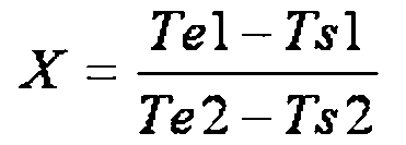
書換後において、表示部10に表示される色は、明度の高い順に「白色」、「ライトグレイ7」、「ライトグレイ6」、「ライトグレイ5」、「ライトグレイ4」、「ライトグレイ3」、「ライトグレイ2」、「ライトグレイ1」、「ダークグレイ7」、「ダークグレイ6」、「ダークグレイ5」、「ダークグレイ4」、「ダークグレイ3」、「ダークグレイ2」、「ダークグレイ1」、「黒色」とする。尚、「白色」の明度は「15」とする。「ライトグレイ7」の明度は「14」とする。「ライトグレイ6」の明度は「13」とする。「ライトグレイ5」の明度は「12」とする。「ライトグレイ4」の明度は「11」とする。「ライトグレイ3」の明度は「10」とする。「ライトグレイ2」の明度は「9」とする。「ライトグレイ1」の明度は「8」とする。「ダークグレイ7」の明度は「7」とする。「ダークグレイ6」の明度は「6」とする。「ダークグレイ5」の明度は「5」とする。「ダークグレイ4」の明度は「4」とする。「ダークグレイ3」の明度は「3」とする。「ダークグレイ2」の明度は「2」とする。「ダークグレイ1」の明度は「1」とする。「黒色」の明度は「0」とする。
反転認識量Rは、平均的な人が、色の反転を認識できる程度の色の明度の量である。反転認識量Rが、表示部10に表示される色の明度の間隔であれば、色の反転は確実に認識される。本実施形態では反転認識量Rを「1」として説明する。Ts1及び、Ts2において表示部10に表示されている色が本発明の書換前の色である。Te1及び、Te2において表示部10に表示されている色が本発明の書換後の色である。図8(C)と図9(C)と図10(C)と図11(C)とに実線で示された曲線が本発明の第1変化曲線L1である。図8(C)と図9(C)と図10(C)と図11(C)とに点線で示された曲線が本発明の第2変化曲線L2である。本実施例では表示部10の色は白色帯電粒子13Aと黒色帯電粒子13Bとの上下方向の移動によって変化する。従って、表示部10の色の変化は連続的であり、第1変化曲線L1と第2変化曲線L2とはTsからTeまでの間で微分可能である。
図8(A)は表示部10の色を「白色」から「白色」へ書き換えるために画素電極12に印加する電圧を表す通常書換波形の波形図である。図8(C)は表示部10の色が「白色」から「白色」へ書き換えられた場合の表示部10に表示される色の明度の変化を表した図である。図8(A)に示したように、通常書換波形では、Ts1から所定時間の間においてプラス電圧が画素電極12に印加される。所定時間が経過するとマイナス電圧が画素電極12に印加される。白色帯電粒子13Aは、まず、透明電極14側から画素電極12側へ移動する。次に白色帯電粒子13Aの移動方向が反転し、白色帯電粒子13Aは画素電極12側から透明電極14側へ移動する。これに対し、黒色帯電粒子13Bは、まず、画素電極12側から透明電極14側へ移動する。次に黒色帯電粒子13Bの移動方向が反転し、黒色帯電粒子13Bは透明電極14側から画素電極12側へ移動する。従って、図8(A)に示したように、第1書換過程において、表示部10に表示される色が「白色」から「ダークグレイ7」を経由して「白色」に書き換えられる。従って、図8(C)で示したように、第1変化曲線L1は極小値Pminをもつ。Tminはこの極小値Pminをとる時点である。TsからTminまでの時間では、表示部10に表示される色は「白色」から「ダークグレイ7」に変化する。従って明度は「15」から「7」に変化する。つまり、明度が下がる。TminからTeまでの時間では「ダークグレイ7」から「白色」に変化する。従って、明度は「7」から「15」に変化する。つまり、明度が上がる。書換前の色の明度と極値をとる時点での明度の差の絶対値である第1反転量R1は「8」である。第1反転量R1は反転認識量Rよりも大きい。
図8(B)は表示部10の色を「白色」から「白色」へ書き換えるために画素電極12に印加する電圧を表す高速書換波形の波形図である。図8(B)に示したように、高速書換波形では「白色」から「白色」へ書き換えられる際は、電圧は印加されない。従って、白色帯電粒子13Aと黒色帯電粒子13Bとは第2書換過程において移動しない。従って、第2書換過程において表示部10に表示される色は「白色」のままである。従って、図8(C)に示したように、第2変化曲線L2は極値Pを持たない。明度は第2書換過程において「15」のままである。また、第1変化曲線L1の全長は第2変化曲線L2の全長よりも長い。
表示部10の色が「白色」から「白色」へ書き換えられる過程において、第1変化曲線L1の全長は、第2変化曲線L2の全長よりも長い。従って、高速書換波形で表示部10の色を書き換えるよりも通常書換波形で表示部10の色を書き換えた方が、画素電極12と透明電極14との間に配置された白色帯電粒子13Aと黒色帯電粒子13Bとの位置の詳細な制御を行うことができる。これにより、残像のすくない表示を行うことができる。さらに、通常書換波形で表示部10の色を書き換えるよりも高速書換波形で表示部10の色を書き換えた方が、画素電極12と透明電極14との間に配置された白色帯電粒子13Aの上下方向の移動と黒色帯電粒子13Bの上下方向の移動が減る。これにより、表示部10に表示される色のちらつきを抑えることができる。さらに、第1変化曲線L1が極値Pを持つように定められた通常書換波形により色が書き換えられる。第2変化曲線L2が極値を持たないように定められた高速書換波形により色が書き換えられる。従って、通常書換波形に従い、色が書き換えられた場合は、黒色帯電粒子13Bの移動方向と白色帯電粒子13Aの移動方向とが第1書換過程において反転する。よって、変化曲線が極値Pを持たないように定められた波形で色が書き換えられる場合よりも、通常書換波形による書き換えは残像をよく消すことができる。さらに第2変化曲線L2が極値を持たないように定められた高速書換波形により色が書き換えられた場合は、黒色帯電粒子13Bの移動方向と白色帯電粒子13Aの移動方向とが第2書換過程において反転しない。よって、変化曲線が極値をもつように定められた波形に従い、色が書き換えられる場合よりも、高速書換波形による書き換えは第2書換過程における色の変化を小さくすることが出来る。これにより、黒色帯電粒子13B及び、白色帯電粒子13Aの画素電極12と透明電極14との間における分布状態の変化による色のちらつきを抑えることが出来る。
第1変化曲線L1が反転認識量Rよりも大きい第1反転量R1をもつように定められた通常書換波形に従い、色が書き換えられる。第1変化曲線L1が極値Pを1つ持つので、黒色帯電粒子13Bの移動方向と白色帯電粒子13Aの移動方向とが書換前から極値Pをとる時点までの間、または極値Pをとる時点から書換後までの間で反転する。この黒色帯電粒子13Bの移動方向と白色帯電粒子13Cの移動方向とが反転している時点における第1反転量R1が反転認識量Rよりも大きいので、変化曲線が反転認識量Rよりも小さい反転量を持つように定められた波形に従い色が書き換えられるよりも、通常書換波形による書き換えは残像をより消すことが出来る。
さらに、隣接する前記階調の色の間隔は、反転認識量R以上であるので、隣接する階調の色の間隔が反転認識量R未満であるように定められた高速書換波形に従い色が書き換えられるよりも第2書換過程における色の変化を抑えることができる。これにより、黒色帯電粒子13B及び、白色帯電粒子13Aの画素電極12と透明電極14との間における分布状態の変化による色のちらつきを抑えることが出来る。
図9(A)は表示部10の色を「白色」から「黒色」へ書き換えるために画素電極12に印加する電圧を表す通常書換波形の波形図である。図9(C)は表示部10の色が「白色」から「黒色」へ書き換えられた場合の表示部10に表示される色の明度の変化を表した図である。図9(A)に示したように、通常書換波形では、Ts1から所定時間の間においてプラス電圧が画素電極12に印加される。所定時間が経過するとマイナス電圧が画素電極12に印加される。マイナス電圧が画素電極12に印加された後に、プラス電圧が画素電極12に印加される。白色帯電粒子13Aは、まず、透明電極14側から画素電極12側へ移動する。次に白色帯電粒子13Aの移動方向が反転し、白色帯電粒子13Aは画素電極12側から透明電極14側へ移動する。次に白色帯電粒子13Aの移動方向が反転し、白色帯電粒子13Aは透明電極14側から画素電極12側へ移動する。これに対し、黒色帯電粒子13Bは、まず、画素電極12側から透明電極14側へ移動する。次に黒色帯電粒子13Bの移動方向が反転し、黒色帯電粒子13Bは透明電極14側から画素電極12側へ移動する。次に黒色帯電粒子13Bの移動方向が反転し、黒色帯電粒子13Bは画素電極12側から透明電極14側へ移動する。従って、図9(A)に示したように、第1書換過程において、「白色」から「ダークグレイ7」と「ライトグレイ4」とを経由して「黒色」に表示部10に表示される色が書き換えられる。従って、図9(C)で示したように、第1変化曲線L1は極大値Pmaxと極小値Pminとをもつ。この極大値Pmaxと極小値Pminとの差の絶対値が第1反転量R1である。Tminはこの極小値Pminをとる時点である。Tmaxはこの極大値Pmaxをとる時点である。TsからTminまでの時間では、表示部10に表示される色は「白色」から「ダークグレイ7」に変化する。従って明度は「15」から「7」に変化する。つまり、明度が下がる。TminからTmaxまでの時間では、表示部10に表示される色は「ダークグレイ7」から「ライトグレイ4」に変化する。従って明度は「7」から「11」に変化する。つまり、明度が上がる。TmaxからTeまでの時間では「ライトグレイ4」から「黒色」に変化する。従って、明度は「11」から「0」に変化する。つまり、明度が下がる。第1反転量R1は「4」である。第1反転量R1は、反転認識量Rよりも大きい。
図9(B)は表示部10の色を「白色」から「黒色」へ書き換えるために画素電極12に印加する電圧を表す高速書換波形の波形図である。図9(B)に示したように、高速書換波形では、Ts2から所定時間の間においてプラス電圧が画素電極12に印加される。所定時間が経過するとプラス電圧が画素電極12に印加される。白色帯電粒子13Aは、TsからTeまでの間で透明電極14側から画素電極12側へ移動する。これに対し、黒色帯電粒子13Bは、TsからTeまでの間で画素電極12側から透明電極14側へ移動する。図9(B)に示したように、第2書換過程において、「白色」から「黒色」に表示部10に表示される色が書き換えられる。従って、図9(C)で示したように、第2変化曲線L2は極値Pを持たない。TsからTeまでの時間では、表示部10に表示される色は「白色」から「黒色」に変化する。従って明度は「15」から「0」に変化する。つまり、明度が下がる。また、第1変化曲線L1の全長は第2変化曲線L2の全長よりも長い。
表示部10の色が「白色」から「黒色」へ書き換えられる過程において、第1変化曲線L1の全長は、第2変化曲線L2の全長よりも長い。従って、高速書換波形で表示部10の色を書き換えるよりも通常書換波形で表示部10の色を書き換えた方が、画素電極12と透明電極14との間に配置された白色帯電粒子13Aと黒色帯電粒子13Bとの位置の詳細な制御を行うことができる。これにより、残像のすくない表示を行うことができる。さらに、通常書換波形で表示部10の色を書き換えるよりも高速書換波形で表示部10の色を書き換えた方が、画素電極12と透明電極14との間に配置された白色帯電粒子13Aの上下方向の移動と黒色帯電粒子13Bの上下方向の移動が減る。これにより、表示部10に表示される色のちらつきを抑えることができる。さらに、第1変化曲線L1が極値Pを持つように定められた通常書換波形により色が書き換えられる。第2変化曲線L2が極値を持たないように定められた高速書換波形により色が書き換えられる。従って、通常書換波形に従い、色が書き換えられた場合は、黒色帯電粒子13Bの移動方向と白色帯電粒子13Aの移動方向とが第1書換過程において反転する。よって、変化曲線が極値Pを持たないように定められた波形で色が書き換えられる場合よりも、通常書換波形による書き換えは残像をよく消すことができる。さらに第2変化曲線L2が極値を持たないように定められた高速書換波形により色が書き換えられた場合は、黒色帯電粒子13Bの移動方向と白色帯電粒子13Aの移動方向とが第2書換過程において反転しない。よって、変化曲線が極値をもつように定められた波形に従い、色が書き換えられる場合よりも、高速書換波形による書き換えは第2書換過程における色の変化を小さくすることが出来る。これにより、黒色帯電粒子13B及び、白色帯電粒子13Aの画素電極12と透明電極14との間における分布状態の変化による色のちらつきを抑えることが出来る。
第1変化曲線L1が反転認識量Rよりも大きい第1反転量R1をもつように定められた通常書換波形に従い、色が書き換えられる。第1変化曲線L1が極大値Pmaxと極小値Pminとを持つので、黒色帯電粒子13Bの移動方向と白色帯電粒子13Aの移動方向とが極大値Pmaxをとる時点Tmaxと極小値Pminをとる時点Tminとの間で反転する。この黒色帯電粒子13Bの移動方向と白色帯電粒子13Cの移動方向とが反転している時点における第1反転量R1が反転認識量Rよりも大きいので、変化曲線が反転認識量Rよりも小さい反転量を持つように定められた波形に従い色が書き換えられるよりも、通常書換波形による書き換えは残像をより消すことが出来る。
さらに、隣接する前記階調の色の間隔は、反転認識量R以上であるので、隣接する階調の色の間隔が反転認識量R未満であるように定められた高速書換波形に従い色が書き換えられるよりも第2書換過程における色の変化を抑えることができる。これにより、黒色帯電粒子13B及び、白色帯電粒子13Aの画素電極12と透明電極14との間における分布状態の変化による色のちらつきを抑えることが出来る。
図10(A)は表示部10の色を「白色」から「ライトグレイ4」へ書き換えるために画素電極12に印加する電圧を表す通常書換波形の波形図である。図10(C)は表示部10の色が「白色」から「ライトグレイ4」へ書き換えられた場合の表示部10に表示される色の明度の変化を表した図である。図10(A)に示したように、通常書換波形では、Ts1から所定時間の間においてプラス電圧が画素電極12に印加される。所定時間が経過するとマイナス電圧が画素電極12に印加される。マイナス電圧が画素電極12に印加された後に、プラス電圧が画素電極12に印加される。白色帯電粒子13Aは、まず、透明電極14側から画素電極12側へ移動する。次に白色帯電粒子13Aの移動方向が反転し、白色帯電粒子13Aは画素電極12側から透明電極14側へ移動する。次に白色帯電粒子13Aの移動方向が反転し、白色帯電粒子13Aは透明電極14側から画素電極12側へ移動する。これに対し、黒色帯電粒子13Bは、まず、画素電極12側から透明電極14側へ移動する。次に黒色帯電粒子13Bの移動方向が反転し、黒色帯電粒子13Bは透明電極14側から画素電極12側へ移動する。次に黒色帯電粒子13Bの移動方向が反転し、黒色帯電粒子13Bは画素電極12側から透明電極14側へ移動する。従って、図10(A)に示したように、第1書換過程において、「白色」から「ダークグレイ7」を経由して「ライトグレイ4」に表示部10に表示される色が書き換えられる。従って、図10(C)で示したように、第1変化曲線L1は極小値Pminをもつ。Tminはこの極小値Pminをとる時点である。TsからTminまでの時間では、表示部10に表示される色は「白色」から「ダークグレイ7」に変化する。従って明度は「15」から「7」に変化する。つまり、明度が下がる。TminからTeまでの時間では、表示部10に表示される色は「ダークグレイ7」から「ライトグレイ4」に変化する。従って明度は「7」から「11」に変化する。つまり、明度が上がる。極小値Pminと書換後の色の明度との差の絶対値である第1反転量R1は「3」である。第1反転量は反転認識量Rよりも大きい。
図10(B)は表示部10の色を「白色」から「ライトグレイ4」へ書き換えるために画素電極12に印加する電圧を表す高速書換波形の波形図である。図10(B)に示したように、高速書換波形では、Ts2から所定時間の間においてマイナス電圧が画素電極12に印加される。これは、表示部10の色が「白色」から「ライトグレイ4」へ高速書換波形により書き換えられる際は、白色帯電粒子13A及び黒色帯電粒子13Bの位置制御が難しい。この理由により、まず最初にマイナス電圧を画素電極12に印加することによって、位置制御を簡易にするためである。所定時間が経過するとプラス電圧が画素電極12に印加される。白色帯電粒子13Aは、透明電極14側から画素電極12側へ移動する。これに対し、黒色帯電粒子13Bは、画素電極12側から透明電極14側へ移動する。図10(B)に示したように、第2書換過程において、「白色」から「ライトグレイ4」に表示部10に表示される色が書き換えられる。従って、図10(C)で示したように、第2変化曲線L2は極値Pを持たない。TsからTeまでの時間では、表示部10に表示される色は「白色」から「黒色」に変化する。従って明度は「15」から「11」に変化する。つまり、明度が下がる。第1変化曲線L1の全長は第2変化曲線L2の全長よりも長い。
表示部10の色が「白色」から「ライトグレイ4」へ書き換えられる過程において、第1変化曲線L1の全長は、第2変化曲線L2の全長よりも長い。従って、高速書換波形で表示部10の色を書き換えるよりも通常書換波形で表示部10の色を書き換えた方が、画素電極12と透明電極14との間に配置された白色帯電粒子13Aと黒色帯電粒子13Bとの位置の詳細な制御を行うことができる。これにより、残像のすくない表示を行うことができる。さらに、通常書換波形で表示部10の色を書き換えるよりも高速書換波形で表示部10の色を書き換えた方が、画素電極12と透明電極14との間に配置された白色帯電粒子13Aの上下方向の移動と黒色帯電粒子13Bの上下方向の移動が減る。これにより、表示部10に表示される色のちらつきを抑えることができる。さらに、第1変化曲線L1が極値Pを持つように定められた通常書換波形により色が書き換えられる。第2変化曲線L2が極値を持たないように定められた高速書換波形により色が書き換えられる。従って、通常書換波形に従い、色が書き換えられた場合は、黒色帯電粒子13Bの移動方向と白色帯電粒子13Aの移動方向とが第1書換過程において反転する。よって、変化曲線が極値Pを持たないように定められた波形で色が書き換えられる場合よりも、通常書換波形による書き換えは残像をよく消すことができる。さらに第2変化曲線L2が極値を持たないように定められた高速書換波形により色が書き換えられた場合は、黒色帯電粒子13Bの移動方向と白色帯電粒子13Aの移動方向とが第2書換過程において反転しない。よって、変化曲線が極値をもつように定められた波形に従い、色が書き換えられる場合よりも、高速書換波形による書き換えは第2書換過程における色の変化を小さくすることが出来る。これにより、黒色帯電粒子13B及び、白色帯電粒子13Aの画素電極12と透明電極14との間における分布状態の変化による色のちらつきを抑えることが出来る。
第1変化曲線L1が反転認識量Rよりも大きい第1反転量R1をもつように定められた通常書換波形に従い、色が書き換えられる。第1変化曲線L1が極値Pを1つ持つので、黒色帯電粒子13Bの移動方向と白色帯電粒子13Aの移動方向とが書換前から極値Pをとる時点までの間、または極値Pをとる時点から書換後までの間で反転する。この黒色帯電粒子13Bの移動方向と白色帯電粒子13Cの移動方向とが反転している時点における第1反転量R1が反転認識量Rよりも大きいので、変化曲線が反転認識量Rよりも小さい反転量を持つように定められた波形に従い色が書き換えられるよりも、通常書換波形による書き換えは残像をより消すことが出来る。
さらに、隣接する前記階調の色の間隔は、反転認識量R以上であるので、隣接する階調の色の間隔が反転認識量R未満であるように定められた高速書換波形に従い色が書き換えられるよりも第2書換過程における色の変化を抑えることができる。これにより、黒色帯電粒子13B及び、白色帯電粒子13Aの画素電極12と透明電極14との間における分布状態の変化による色のちらつきを抑えることが出来る。
図11(A)は表示部10の色を「白色」から「ダークグレイ7」へ書き換えるために画素電極12に印加する電圧を表す通常書換波形の波形図である。図11(C)は表示部10の色が「白色」から「ダークグレイ7」へ書き換えられた場合の表示部10に表示される色の明度の変化を表した図である。図11(A)に示したように、通常書換波形では、Ts1から所定時間の間においてプラス電圧が画素電極12に印加される。所定時間が経過するとマイナス電圧が画素電極12に印加される。マイナス電圧が画素電極12に印加された後に、プラス電圧が画素電極12に印加される。白色帯電粒子13Aは、まず、透明電極14側から画素電極12側へ移動する。次に白色帯電粒子13Aの移動方向が反転し、白色帯電粒子13Aは画素電極12側から透明電極14側へ移動する。次に白色帯電粒子13Aの移動方向が反転し、白色帯電粒子13Aは透明電極14側から画素電極12側へ移動する。これに対し、黒色帯電粒子13Bは、まず、画素電極12側から透明電極14側へ移動する。次に黒色帯電粒子13Bの移動方向が反転し、黒色帯電粒子13Bは透明電極14側から画素電極12側へ移動する。次に黒色帯電粒子13Bの移動方向が反転し、黒色帯電粒子13Bは画素電極12側から透明電極14側へ移動する。第1書換過程において、「白色」から「ライトグレイ1」と「ライトグレイ6」とを経由して「ダークグレイ7」に表示部10に表示される色が書き換えられる。従って、図11(C)で示したように、第1変化曲線L1は極大値Pmax1と極小値Pmin1とをもつ。この極大値Pmax1と極小値Pmin1との差の絶対値が第2反転量R2である。Tmax1はこの極大値Pmax1をとる時点である。Tmin1はこの極小値Pmin1をとる時点である。TsからTmin1までの時間では、表示部10に表示される色は「白色」から「ライトグレイ1」に変化する。従って明度は「15」から「8」に変化する。つまり、明度が下がる。Tmin1からTmax1までの時間では、表示部10に表示される色は「ライトグレイ1」から「ライトグレイ6」に変化する。従って明度は「8」から「13」に変化する。つまり、明度が上がる。Tmax1からTeまでの時間では「ライトグレイ6」から「ダークグレイ7」に変化する。従って、明度は「13」から「7」に変化する。つまり、明度が下がる。第2反転量R2は「5」である。第2反転量R2は反転認識量Rよりも大きい。
図11(B)は表示部10の色を「白色」から「ダークグレイ7」へ書き換えるために画素電極12に印加する電圧を表す高速書換波形の波形図である。図11(B)に示したように、高速書換波形では、Ts2から所定時間の間においてプラス電圧が画素電極12に印加される。所定時間が経過するとマイナス電圧が画素電極12に印加される。マイナス電圧が画素電極12に印加された後に、プラス電圧が画素電極12に印加される。白色帯電粒子13Aは、まず、透明電極14側から画素電極12側へ移動する。次に白色帯電粒子13Aの移動方向が反転し、白色帯電粒子13Aは画素電極12側から透明電極14側へ移動する。次に白色帯電粒子13Aの移動方向が反転し、白色帯電粒子13Aは透明電極14側から画素電極12側へ移動する。これに対し、黒色帯電粒子13Bは、まず、画素電極12側から透明電極14側へ移動する。次に黒色帯電粒子13Bの移動方向が反転し、黒色帯電粒子13Bは透明電極14側から画素電極12側へ移動する。次に黒色帯電粒子13Bの移動方向が反転し、黒色帯電粒子13Bは画素電極12側から透明電極14側へ移動する。第2書換過程において、「白色」から「ライトグレイ2.5」と「ライトグレイ3」とを経由して「ダークグレイ7」に表示部10に表示される色が書き換えられる。「ライトグレイ2.5」は「ライトグレイ2」と「ダークグレイ3」との間の階調の色である。「ライトグレイ2.5」の明度は「9.5」である。従って、図11(C)で示したように、第2変化曲線L2は極大値Pmax2と極小値Pmin2とをもつ。極大値Pmax2と極小値Pmin2との差の絶対値が第3反転量R3である。Tmax2はこの極大値Pmax2をとる時点である。Tmin2はこの極小値Pmin2をとる時点である。TsからTmin2までの時間では、表示部10に表示される色は「白色」から「ライトグレイ2.5」に変化する。従って明度は「15」から「9.5」に変化する。つまり、明度が下がる。Tmin2からTmax2までの時間では、表示部10に表示される色は「ライトグレイ2.5」から「ライトグレイ3」に変化する。従って明度は「9.5」から「10」に変化する。つまり、明度が上がる。Tmax2からTeまでの時間では「ライトグレイ3」から「ダークグレイ7」に変化する。従って、明度は「10」から「7」に変化する。つまり、明度が下がる。第3反転量R3は「0.5」である。第3反転量R3は反転認識量Rよりも小さい。また、第1変化曲線L1の全長は第2変化曲線L2の全長よりも長い。第3反転量R3は反転認識量Rよりも小さい。
表示部10の色が「白色」から「ダークグレイ7」へ書き換えられる過程において、第1変化曲線L1の全長は、第2変化曲線L2の全長よりも長い。従って、高速書換波形で表示部10の色を書き換えるよりも通常書換波形で表示部10の色を書き換えた方が、画素電極12と透明電極14との間に配置された白色帯電粒子13Aと黒色帯電粒子13Bとの位置の詳細な制御を行うことができる。これにより、残像のすくない表示を行うことができる。さらに、通常書換波形で表示部10の色を書き換えるよりも高速書換波形で表示部10の色を書き換えた方が、画素電極12と透明電極14との間に配置された白色帯電粒子13Aの上下方向の移動と黒色帯電粒子13Bの上下方向の移動が減る。これにより、表示部10に表示される色のちらつきを抑えることができる。さらに、第1変化曲線L1が極値Pを持つように定められた通常書換波形により色が書き換えられる。第2変化曲線L2が極値を持たないように定められた高速書換波形により色が書き換えられる。従って、通常書換波形に従い、色が書き換えられた場合は、黒色帯電粒子13Bの移動方向と白色帯電粒子13Aの移動方向とが第1書換過程において反転する。よって、変化曲線が極値Pを持たないように定められた波形で色が書き換えられる場合よりも、通常書換波形による書き換えは残像をよく消すことができる。さらに第2変化曲線L2が極値を持たないように定められた高速書換波形により色が書き換えられた場合は、黒色帯電粒子13Bの移動方向と白色帯電粒子13Aの移動方向とが第2書換過程において反転しない。よって、変化曲線が極値をもつように定められた波形に従い、色が書き換えられる場合よりも、高速書換波形による書き換えは第2書換過程における色の変化を小さくすることが出来る。これにより、黒色帯電粒子13B及び、白色帯電粒子13Aの画素電極12と透明電極14との間における分布状態の変化による色のちらつきを抑えることが出来る。
第1変化曲線L1が反転認識量Rよりも大きい第2反転量R1をもつように定められた通常書換波形に従い、色が書き換えられる。第1変化曲線L1が極大値Pmax1と極小値Pmin1とを持つので、黒色帯電粒子13Bの移動方向と白色帯電粒子13Aの移動方向とが極大値Pmax1をとる時点Tmax1と極小値Pmin1をとる時点Tmin1との間で反転する。この黒色帯電粒子13Bの移動方向と白色帯電粒子13Cの移動方向とが反転している時点における第2反転量R2が反転認識量Rよりも大きいので、変化曲線が反転認識量Rよりも小さい反転量を持つように定められた波形に従い色が書き換えられるよりも、通常書換波形による書き換えは残像をより消すことが出来る。
さらに、隣接する前記階調の色の間隔は、反転認識量R以上であるので、隣接する階調の色の間隔が反転認識量R未満であるように定められた高速書換波形に従い色が書き換えられるよりも第2書換過程における色の変化を抑えることができる。これにより、黒色帯電粒子13B及び、白色帯電粒子13Aの画素電極12と透明電極14との間における分布状態の変化による色のちらつきを抑えることが出来る。
さらに、第3反転量R3が第2反転量R2よりも小さいので、第3反転量R3が第2反転量R2よりも大きいように定められた波形に従い、書換指示が記憶されている状態で色が書き換えられるよりも、高速書換波形による書き換えは、黒色帯電粒子13B及び、白色帯電粒子13Aの画素電極12と透明電極14との間における分布状態の変化による色のちらつきを抑えることが出来る。
さらに、第2反転量R2は反転認識量Rよりも大きく、第3反転量R3は反転認識量Rよりも小さい。従って、変化曲線が反転認識量Rよりも小さい第2反転量R2をもつように定められた波形に従い、色が書き換えられるよりも、通常書換波形による書き換えは残像をより消すことが出来る。変化曲線が反転認識量Rよりも大きい第3反転量R3をもつように定められた波形により色が書き換えられるよりも、高速書換による書き換えは第2書換過程における色の変化を抑えることができる。これにより、黒色帯電粒子13B及び、白色帯電粒子13Aの画素電極12と透明電極14との間における分布状態の変化による色のちらつきを抑えることが出来る。
<表示部の電気的構成>
表示部10は、ゲートドライバ16と、ソースドライバ17と、薄膜トランジスタ18(Thin Film Transistor:以下「TFT」)とを有する。表示コントローラ50は、ゲートドライバ16とソースドライバ17と、制御部30と、波形記憶部60とに接続される。TFT18は、ゲートドライバ16とソースドライバ17とに接続される。表示コントローラ50、ゲートドライバ16とソースドライバ17及びTFT18が、本発明の書換部の一例である。
表示部10は、ゲートドライバ16と、ソースドライバ17と、薄膜トランジスタ18(Thin Film Transistor:以下「TFT」)とを有する。表示コントローラ50は、ゲートドライバ16とソースドライバ17と、制御部30と、波形記憶部60とに接続される。TFT18は、ゲートドライバ16とソースドライバ17とに接続される。表示コントローラ50、ゲートドライバ16とソースドライバ17及びTFT18が、本発明の書換部の一例である。
<ドライバとTFTの接続関係>
図12は、本実施形態における表示部10の詳細な構成を示している。図12に示したように、ゲートドライバ16は、多数のゲート線16Aと接続される。ソースドライバ17は、多数のソース線17Aと接続される。ゲート線16Aとソース線17Aとは、互いに交差するように配線される。TFT18が、ゲート線16Aとソース線17Aとの各交差部近傍に配置される。TFT18のゲート端子18Aがゲート線16Aに接続される。TFT18のソース端子18Bがソース線17Aに接続される。TFT18のドレイン端子18Cが画素電極12に接続される。
図12は、本実施形態における表示部10の詳細な構成を示している。図12に示したように、ゲートドライバ16は、多数のゲート線16Aと接続される。ソースドライバ17は、多数のソース線17Aと接続される。ゲート線16Aとソース線17Aとは、互いに交差するように配線される。TFT18が、ゲート線16Aとソース線17Aとの各交差部近傍に配置される。TFT18のゲート端子18Aがゲート線16Aに接続される。TFT18のソース端子18Bがソース線17Aに接続される。TFT18のドレイン端子18Cが画素電極12に接続される。
ゲートドライバ16は、TFT18をオンにするためのゲート制御電圧をゲート線16Aを介してゲート端子18Aに供給する。ソースドライバ17は、ソース線17Aを介して、プラス電圧またはマイナス電圧をソース端子18Bに供給する。従って、ゲート制御電圧が、ゲート端子18Aに印加されている時に、このプラス電圧またはマイナス電圧が画素電極12に印加される。表示コントローラ50は、ゲートドライバ16がゲート線16Aに供給するゲート制御電圧と、ソースドライバ17がソース線17Aに印加する駆動パルス電圧とを制御し、画素電極12にプラス電圧またはマイナス電圧を印加する。
<表示装置1の動作の説明>
以上説明した構成からなる本実施形態の表示装置1の動作及び作用について、図13~図17を参照して説明する。図13、図15、図16、図17は、制御部30の全体処理の手順を示すフローチャートである。電源キー21が押下されて、電力が制御部30に供給された後に、制御部30が全体処理を実行する。図13に示す処理は全て制御部30が行う。図14は制御部30の入力キーデータ取得タスクの手順を示すフローチャートである。
以上説明した構成からなる本実施形態の表示装置1の動作及び作用について、図13~図17を参照して説明する。図13、図15、図16、図17は、制御部30の全体処理の手順を示すフローチャートである。電源キー21が押下されて、電力が制御部30に供給された後に、制御部30が全体処理を実行する。図13に示す処理は全て制御部30が行う。図14は制御部30の入力キーデータ取得タスクの手順を示すフローチャートである。
図13に示したように、ステップ1(以下ステップをSと称す)では、制御部30は、入力キーデータ取得タスクを開始し、S2に移行する。この入力キーデータ取得タスクは、制御部30が、全体処理と並行して処理を行う。
図14に示したフローチャートに従い、入力キーデータ取得タスクを説明する。図14に示したように、S101では、制御部30は、入力キー22が押下されることにより発生する電気信号を取得し、S102に移行する。
S102では、制御部30は、S101で取得した電気信号に基づいて、入力キー22が押下されたかを判断する。入力キー22が押下されたと判断された場合(S102:Yes)は、S103に移行する。入力キー22が押下されていないと判断された場合(S102:No)は、S104に移行する。
S103では、制御部30は、S101で取得した電気信号に対応する入力キーデータを書換指示記憶部321に記憶し、S104に移行する。入力キーデータはS101において押下された入力キー22を識別するためのデータである。より具体的には、メニューキー23が押下された場合は、入力キーデータであるメニューキーデータを書換指示記憶部321に記憶する。閉じるキー24が押下された場合は、入力キーデータである閉じるキーデータを書換指示記憶部321に記憶する。前キー25が押下された場合は、入力キーデータである前キーデータを書換指示記憶部321に記憶する。次キー26が押下された場合は、入力キーデータである次キーデータを書換指示記憶部321に記憶する。選択キー27が押下された場合は、入力キーデータである選択キーデータを書換指示記憶部321に記憶する。決定キー28が押下された場合は、決定キーデータである決定キーデータを書換指示記憶部321に記憶する。
S104では、制御部30は、タイマー開始信号をタイマー34に送信し、タイマー34を起動させる。タイマー開始信号を受信したタイマー34は、20ms計時し、計時が終了すると、制御部30にタイマー終了信号を送信する。制御部30は、タイマー終了信号を受信すると、S101に戻る。このS104の処理があることにより、制御部30に負荷がかかるのを防ぐことが出来る。
図13に戻って、全体処理の説明を再開する。図13に示したように、S2では、制御部30は、メモリカード41に記憶されている複数の文書ファイル410から複数のタイトルデータ410Tを、メモリカードインターフェース40を介して取得する。そして制御部30は、取得したタイトルデータ410の一覧を作成する。制御部30は、作成したタイトルデータ410Tの一覧をRAM32に記憶させ、S3に移行する。
S3では、制御部30は、S2においてRAM32に記憶されたタイトルデータ410Tの一覧の先頭に配置されたタイトルデータ410Tに対してカーソルを設定し、S4に移行する。
S4では、制御部30は、タイトルデータ410Tの一覧に基づいてタイトルの一覧を表示させる。表示部10には、タイトルの一覧が表示される。尚、カーソルが設定されたタイトルデータ410Tに対応するタイトルは、カーソルに囲まれているように表示される。そして、制御部30は、S5に移行する。制御部30はタイトルの一覧を表示させる際、書換モードを通常書換モードに設定し、書換モードデータを作成する。書換モードデータとは、通常書換モードか高速書換モードが指定された書換モードを示すデータである。制御部30は、タイトルデータ410Tの一覧の画像データを作成する。制御部30は、作成したタイトルデータ410Tの一覧の画像データと現表示色データD1とから画素毎に書換前の色と書換後の色とを示した差分データを作る。制御部30は、書換モードデータと差分データとを表示コントローラ50に送信する。さらに制御部30は、現表示色データD1を書換後の色のデータに書き換える。書換モードデータと差分データとを受信した表示コントローラ50は、波形記憶部60から通常書換波形データを読み出す。次に、表示コントローラ50は、読み出した通常書換波形データに従い、ゲートドライバ16及びソースドライバ17を制御する。通常書換波形データに従う電圧が、各画素電極12に印加される。表示部10の色が書き換えられる。
S5では、制御部30は、入力キーデータ取得処理を開始する。制御部30は、入力キーデータ取得処理を終えると、S6に移行する。入力キーデータ取得処理は後述するが、書換指示記憶部321に記憶されている入力キーデータを表示データ記憶部322に取得する処理である。制御部30は、入力キーデータを表示データ記憶部322に取得すると、S6に移行する。
図15に示したフローチャートに従い、入力キーデータ取得処理を説明する。図15に示したようにS201では、書換指示記憶部321に記憶された入力キーデータを書換指示記憶部321から表示データ記憶部322に取得し、S202に移行する。
S202では、制御部30は、入力キーデータが書換指示記憶部321のキーバッファ1に記憶されているかを判断する。入力キーデータが書換指示記憶部321に記憶されていると判断した場合(S202:Yes)は、書換指示記憶部321のキーバッファ1に記憶されている入力キーデータを読み取り、S203以下の処理に移行する。入力キーデータが書換指示記憶部321に記憶されていないと判断した場合(S202:No)は、S201に戻る。
S203では、制御部30は、書換指示記憶部321のキーバッファ1に記憶された入力キーデータをキーバッファ1から削除する。次に、制御部30は、入力キーデータがキーバッファ2に記憶されていれば、この入力キーデータをキーバッファ1に移す。次に、制御部30は入力キーデータがキーバッファ3に記憶されていれば、この入力キーデータをキーバッファ2に移し、処理を抜ける。
図13に示したように、S6では、制御部30は、S202において表示データ記憶部322に読み取った入力キーデータが次キーデータであるかを判断する。S202において読み取った入力キーデータが次キーデータであると判断した場合は(S6:Yes)、S7に移行する。S202において読み取った入力キーデータが次キーデータでないと判断した場合は(S6:No)、S8に移行する。
S7では、制御部30は、タイトルの一覧の中のいずれか1つのタイトルに設定されていたカーソルを次のタイトルデータ410Tに設定し、S4の処理に戻る。
S8では、制御部30は、S202において読み取った入力キーデータが、前キーデータであるかを判断する。S202において読み取った入力キーデータが前キーデータであると判断した場合は(S8:Yes)、S9に移行する。S202において読み取った入力キーデータが前キーデータでないと判断した場合は(S8:No)、S10に移行する。
S9では、制御部30は、タイトルの一覧の中の1つのタイトルに設定されていたカーソルを前のタイトルデータ410Tに設定し、S4の処理に戻る。
S10では、制御部30は、S202において読み取った入力キーデータが決定キーデータであるかを判断する。S202において読み取った入力キーデータが決定キーデータであると判断した場合は(S10:Yes)、S20に移行する。S202において読み取った入力キーデータが決定キーデータでないと判断した場合は(S10:No)、S4に戻る。
S20以降の処理を図16に示したフローチャートに従い、説明する。S20では、制御部30は、S10において、決定キーが入力された時点でのカーソルが配置されたタイトルデータと関連付けられた文書ファイル410から最後のページのページ番号データを取得し、表示データ記憶部322に記憶する。
S21では、制御部30は、現在ページのページ番号を「1」としてRAM32に記憶する。現在ページとは、表示部10に現在表示されているページ画像データに関連付けられたページ番号データである。制御部30は、S10において、決定キーが入力された時点でのカーソルが配置されたタイトルデータ410Tと関連付けられた文書ファイル410からページ1画像データ411Cをメモリカード41から取得する。次に、制御部30は、取得したページ1画像データを表示データ記憶部322に記憶する。次に、制御部30は、取得したページ画像データと現表示色データD1とから画素毎に書換前の色と書換後の色とを示した差分データを作る。次に制御部30は書換モードを通常書換モードに設定する。制御部30は、書換モードデータと差分データとを表示コントローラ50に送信し、S22に移行する。さらに制御部30は、現表示色データD1を書換後の色のデータに書き換える。書換モードデータと差分データとを受信した表示コントローラ50は、波形記憶部60から通常書換波形データを読み出す。次に、表示コントローラ50は、読み出した通常書換波形データに従い、ゲートドライバ16及びソースドライバ17を制御する。通常書換波形データに従う電圧が、各画素電極12に印加される。表示部10の色が書き換えられる。
S22では、制御部30は、入力キーデータ取得処理を開始する。制御部30は、入力キーデータ取得処理を終えると、S23に移行する。
S23では、制御部30は、S202において読み取った入力キーデータが次キーデータであるか判断する。S202において読み取った入力キーデータが次キーデータであると判断した場合(S23:Yes)は、S24に移行する。S202において読み取った入力キーデータが次キーデータでないと判断した場合(S23:No)は、S29に移行する。
S24では、制御部30は、次ページ書換イベントをキーイベントとして設定し、S25に移行する。次ページ書換イベントとは、現在表示されているページを次のページに次書き換えるイベントである
S25では、制御部30は、現在ページの次のページ番号データをメモリカードインターフェース40を介して取得し、S26に移行する。
S25では、制御部30は、現在ページの次のページ番号データをメモリカードインターフェース40を介して取得し、S26に移行する。
S26では、制御部30は、現在ページの次のページ番号データがメモリカード41に記憶されているかを判断する。つまり、現在ページがその文書ファイルの最終ページ番号データであるかを判断する。現在ページの次のページ番号データがメモリカード41に記憶されていると判断した場合(S26:Yes)は、S27に移行する。現在ページの次のページ番号データがメモリカード41に記憶されていないと判断した場合(S26:No)は、S22に戻る。
S27では、制御部30は、現在ページの次のページ番号データと関連付けられたページ画像データをメモリカード41からメモリカードインターフェース40を介して取得し、S27に移行する。
S28では、制御部30は、画像書換処理を開始する。画像書換処理が終了したら、S22に戻る。
以下、図17に示したフローチャートに従って、画像書換処理を説明する。S301では、制御部30は、入力キーデータが書換指示記憶部321に記憶されているかをチェックし、S302に移行する。
S302では、制御部30は、書換指示記憶部321に入力キーデータが記憶されているかを判断する。書換指示記憶部321に入力キーデータが記憶されていると判断した場合(S:302:Yes)は、S303に移行する。書換指示記憶部321に入力キーのデータが記憶されていないと判断した場合(S302:No)は、S307に移行する。
S303では、制御部30は、キーイベントが次ページ書換イベントかを判断する。キーイベントが次ページ書換イベントであると判断した場合(S303:Yes)は、S304に移行する。キーイベントが次ページ書換イベントでないと判断した場合(S303:No)は、S308に移行する。
S304では、制御部30は、キーバッファ1に記憶されている入力キーデータが、次キーデータか判断する。キーバッファ1に記憶されている入力キーデータが、次キーデータであると判断した場合、S305に移行する。キーバッファ1に記憶されている入力キーデータが、次キーデータでないと判断した場合、S309に移行する。
S305では、制御部30は、高速書換モードを書換モードに設定し、書換モードデータを作成する。そして、S306に移行する。
S306では、制御部30は、キーイベントに設定された次ページ書換指示または前ページ書換指示に従い、現在ページの次のページ番号データに関連付けられたページ画像データまたは現在ページの前のページ番号データに関連付けられたページ画像データをメモリカードインタフェース40を介して、メモリカード40から取得する。取得したページ画像データと現表示色データD1とから画素毎に書換前の色と書換後の色とを示した差分データを作る。制御部30は、書換モードデータと差分データとを表示コントローラ50に送信する。さらに制御部30は、現表示色データD1を書換後の色のデータに書き換える。書換モードデータと差分データとを受信した表示コントローラ50は、波形記憶部60から通常書換波形データを読み出す。次に、表示コントローラ50は、読み出した通常書換波形データに従い、ゲートドライバ16及びソースドライバ17を制御する。通常書換波形データに従う電圧が、各画素電極12に印加され、表示部10の色が書き換えられる。そして、制御部30は、画面書換処理を抜ける。尚、S306が本発明の書換ステップの一例である。
S307では、制御部30は、通常書換モードを書換モードに設定し、書換モードデータを作成する。そして、S306に移行する。尚、S301~S305、S307が本発明の波形判断ステップである。
S308では、制御部30は、キーバッファ1に記憶されている入力キーデータが、前キーデータか判断する。キーバッファ1に記憶されている入力キーデータが、前キーデータであると判断した場合、S305に移行する。キーバッファ1に記憶されている入力キーデータが、前キーデータでないと判断した場合、S309に移行する。
S309では、制御部30は、キーイベントに設定された次ページ書換イベントまたは前ページ書換イベントを削除し、画面書換処理を抜ける。
S29では、制御部30は、S202において読み取った入力キーデータが前キーデータであるか判断する。S202において読み取った入力キーデータが前キーデータであると判断した場合(S29:Yes)は、S30に移行する。S202において読み取った入力キーデータが前キーデータでないと判断した場合(S29:No)は、S33に移行する。
S30では、制御部30は、前ページ書換イベントをキーイベントとして設定し、S31に移行する。前ページ書換イベントとは、現在表示されているページを前のページに書き換えるイベントである。
S31では、制御部30は、現在ページの前のページ番号データをメモリカードインターフェース40を介して取得し、S32に移行する。
S32では、制御部30は、現在ページの前のページ番号データがメモリカード41に記憶されているかを判断する。つまり、現在ページがその文書ファイルの先頭ページ番号データであるかを判断する。現在ページの前のページ番号データがメモリカード41に記憶されていると判断した場合(S32:Yes)は、S27に移行する。現在ページの前のページ番号データがメモリカード41に記憶されていないと判断した場合(S32:No)は、S22に戻る。
S33では、制御部30は、S202において読み取った入力キーデータが閉じるキーデータであるか判断する。S202において読み取った入力キーデータが閉じるキーデータであると判断した場合(S33:Yes)は、S2に移行する。S202において読み取った入力キーデータが閉じるキーデータでないと判断した場合(S33:No)は、S34に移行する。
S34では、制御部30は、入力キーデータが、電源キーデータかメニューキーデータか選択キーデータであると判断する。制御部30は、S34において判断した入力キーデータに応じた処理を行い、S22に戻る。この詳細な処理は本発明とは関係ないので説明を省略する。
第1変化曲線L1の全長は第2変化曲線L2の全長よりも長い。従って、表示部10に表示されている色が通常書換波形に従って書き換えられた場合は、表示部10に表示されていた色の残像が消されることになる。第2変化曲線L2の全長は第1変化曲線L1の全長よりも短い。従って、表示部10に表示されている色が高速書換波形に従って書き換えられた場合は、黒色帯電粒子13B及び、白色帯電粒子13Aの画素電極12と透明電極14の間における分布状態の変化による色のちらつきが、通常書換波形により色が書き換えられ場合よりも抑えられる。連続して書換指示が入力部に入力された場合、通常書換波形に従い、色を書き換える回数を減らすことが出来る。これにより、黒色帯電粒子13B及び、白色帯電粒子13Aの画素電極12と透明電極14の間における分布状態の変化による色のちらつきを抑えることが出来る。入力キーデータが連続して入力された場合、制御部30は、連続して入力された入力キーデータの内、最後に入力された入力キーデータ以外の入力キーデータに従い、色のちらつきが抑えられる高速書換で色を書き換える。制御部30は、連続して入力された入力キーデータの内、最後に入力された入力キーデータに従い、残像が消される通常書換波形で色を書き換える。よって、連続して入力キーデータが入力部20に入力された場合、通常書換波形に従い、色を書き換える回数を減らすことが出来る。これにより、黒色帯電粒子13B及び、白色帯電粒子13Aの画素電極12と透明電極14との間における分布状態の変化による色のちらつきを抑えることが出来る。
制御部30は、キーイベントに設定された入力キーデータが次キーデータであると判断する。制御部30が判断した入力キーデータの次に入力された入力キーデータが前ページキーデータであると判断する場合がある。制御部30は、キーイベントに設定された入力キーデータが前キーデータであると判断する。制御部30が判断した入力キーデータの次に入力された入力キーデータが前キーデータであると判断する場合がある。この2つの場合において、制御部30は、キーイベントに設定された入力キーデータに従い表示部10に表示されている色を書き換えることを中止させる。従って、高速書換波形で色を書き換える回数を減らすことが出来る。これにより、これにより、黒色帯電粒子13B及び、白色帯電粒子13Aの画素電極12と透明電極14との間における分布状態の変化による色のちらつきを抑えることが出来る。
高速書換波形に従い、色が書き換えられる時間は、通常書換波形に従い、色が書き換えられる時間よりも短い。従って、入力部20に連続して入力された入力キーデータの内、最後の入力キーデータに従い、書き換えられる色が表示されるまでの時間を短くすることが出来る。
なお、この発明は上記の実施例や実施形態に限られるものではなく、その要旨を逸脱しない範囲において種々の態様において実施することが可能であり、例えば次のような変形も可能である。
本実施形態では明度の変化を基準に色のちらつきを定義した。輝度の変化を基準に色のちらつきが定義されてもよい。輝度が用いられた場合、ユーザが表示装置1を400ルクスの明るさで見たときは、隣接する階調の色の間隔は約5cd/m2である。通常書換波形で表示部10に表示される色が書き換えられたときは、第1反転量R1と、第2反転量R2とは5cd/m2以上であってもよい。高速書換波形で表示部10に表示される色が書き換えられたときは、第3反転量R3は5cd/m2未満であるとよい。
本実施形態では明度の変化を基準に色のちらつきを定義した。コントラストの変化を基準に色のちらつきが定義されてもよい。コントラストは白の輝度を黒の輝度で除した値で計算される。
本実施形態では、第1書換過程により色が書き換えられる時間は第2書換過程により色が書き換えられる時間よりも短くてもよい。第1書換過程により色が書き換えられる時間は第2書換過程により色が書き換えられる時間と同じでもよい。
本実施形態では、表示部10はアクティブマトリクス方式であったが、パッシブマトリクス方式で構成されていてもよい。
本実施形態では「白色」から「白色」へ表示部10の色が書き換わる過程と、「白色」から「黒色」へ表示部10の色が書き換わる過程と、「白色」から「ライトグレイ4」へ表示部10の色が書き換わる過程と、「白色」から「ダークグレイ7」へ表示部10の色が書き換わる過程と、を説明した。これに限られず、表示部10に表示される色が書き換えられる過程であればよい。具体的には、「黒色」から「白色」へ書き換えられる過程と、「黒色」から「黒色」へ書き換えられる過程と、「黒色」から「ライトグレイ4」へ書き換えられる過程と、「黒色」から「ダークグレイ7」へ書き換えられる過程と、「ライトグレイ4」から「白色」へ書き換えられる過程と、「ライトグレイ4」から「黒色」へ書き換えられる過程と、「ライトグレイ4」から「ライトグレイ4」へ書き換えられる過程と、「ライトグレイ4」から「ダークグレイ7」へ書き換えられる過程と、「ダークグレイ7」から「白色」へ書き換えられる過程と、「ダークグレイ7」から「黒色」へ書き換えられる過程と、「ダークグレイ7」から「ライトグレイ4」へ書き換えられる過程と、「ダークグレイ7」から「ダークグレイ7」へ書き換えられる過程と、がある。
1 表示装置
10 表示部
12 画素電極
13 マイクロカプセル
13A 白色帯電粒子
13B 黒色帯電粒子
14 透明電極
20 入力部
21 電源キー
22 入力キー
25 前キー
26 次キー
30 制御部
31 CPU
32 RAM
321 書換指示記憶部
33 ROM
34 タイマー
40 メモリカードインタフェース
41 メモリカード
410 文書ファイル
50 表示コントローラ
60 波形記憶部
P1 全体処理プログラム
P2 入力キーデータ取得タスクプログラム
L1 第1変化曲線
L2 第2変化曲線
10 表示部
12 画素電極
13 マイクロカプセル
13A 白色帯電粒子
13B 黒色帯電粒子
14 透明電極
20 入力部
21 電源キー
22 入力キー
25 前キー
26 次キー
30 制御部
31 CPU
32 RAM
321 書換指示記憶部
33 ROM
34 タイマー
40 メモリカードインタフェース
41 メモリカード
410 文書ファイル
50 表示コントローラ
60 波形記憶部
P1 全体処理プログラム
P2 入力キーデータ取得タスクプログラム
L1 第1変化曲線
L2 第2変化曲線
Claims (9)
- 対向する1対の電極間に、第1の色を有し且つ、プラス極性の第1帯電粒子と、第2の色を有し且つ、マイナス極性の第2帯電粒子とが配置され、両電極間に電圧が印加されることにより第1帯電粒子及び第2帯電粒子の配置が変化し、第1の色と、第2の色と、第1の色と第2の色との混色である第3の色と、のいずれかの色の表示が可能な表示部と、
書換前の色から書換後の色へ前記表示部の色が書き換えられる第1書換過程において、前記表示部に表示される色の変化が第1変化曲線となるように定められた第1波形と、前記第1書換過程と同じ前記書換前の色から同じ前記書換後の色へ前記表示部の色が書き換えられる第2書換過程において、前記書換前の色から前記書換後の色まで変化する前記第1変化曲線の全長よりも、前記書換前の色から前記書換後の色まで変化する全長が短い第2変化曲線となるように定められた第2波形と、を記憶する波形記憶部と、
前記表示部に表示された色の書換を指示する書換指示が入力される入力部と、
前記入力部に入力された前記書換指示を記憶する書換指示記憶部と、
前記書換指示記憶部に記憶された前記書換指示を読み取る書換指示読取部と、
前記表示部に表示されている色を書き換える波形が、前記第1波形か前記第2波形かを判断する波形判断部と、
前記波形判断部によって判断した前記第1波形または前記第2波形と、前記書換指示読取部によって読み取られた前記書換指示とに従い、電圧を前記両電極に印加することにより、前記表示部に表示されている色を書き換える書換部と、
を備え、
前記波形判断部は、前記書換指示読取部によって読み取られた前記書換指示の次の前記書換指示が前記書換指示記憶部に記憶されていれば、前記表示部に表示されている色を書き換える波形は前記第2波形であると判断し、前記書換指示読取部によって読み取られた前記書換指示の次の前記書換指示が前記書換指示記憶部に記憶されていなければ、前記表示部に表示されている色を書き換える波形は前記第1波形であると判断すること
を特徴とする表示装置。 - 請求項1に記載の表示装置において、
前記波形記憶部は、前記第1変化曲線が極値を持つように定められた前記第1波形と、前記第2変化曲線が前記極値を持たないように定められた前記第2波形とを記憶することを特徴とする表示装置。 - 請求項2に記載の表示装置において、
前記波形記憶部は、前記第1変化曲線が極大値と極小値とを持つ場合には、前記極大値と前記極小値との差が第1反転量であるように定められ、前記第1変化曲線が前記極値を1つ持つ場合には、前記極値と前記書換前の色との差の絶対値と、前記極値と前記書換後の色との差の絶対値と、のいずれか一方の値が前記第1反転量であるように定められた前記第1波形を記憶し、
前記第1反転量は、前記表示部に表示される色が反転されたと認識される色の変化量である反転認識量よりも大きいこと
を特徴とする表示装置。 - 請求項1に記載の表示装置において、
前記波形記憶部は、前記第1変化曲線が第1極大値と第1極小値とを持つように定められた前記第1波形と、前記第2変化曲線が、第2極大値と第2極小値とを持つように定められた前記第2波形と、を記憶し、
前記第2極大値と前記第2極小値との差である第3反転量は、前記第1極大値と前記第1極小値との差である第2反転量よりも小さいこと
を特徴とする表示装置。 - 請求項4に記載の表示装置において、
前記波形記憶部は、前記第2反転量が、前記表示部に表示される色が反転されたと認識される反転認識量よりも大きい前記第1変化曲線となるように定められた第1波形と、前記第3反転量が、前記反転認識量よりも小さい前記第2変化曲線となるように定められた前記第2波形と、を記憶すること
を特徴とする表示装置。 - 請求項3または5に記載の表示装置において、
前記書換前の色と前記書換後の色とは、前記第1の色から前記第2の色までの離散的な階調の色であって、
隣接する前記階調の色の間隔は、前記反転認識量以上であること
を特徴とする表示装置。 - 請求項1に記載の表示装置において、
前記書換指示が次ページ書換か前ページ書換かを判断する書換指示判断部と、
前記書換指示判断部が、前記書換指示読取部によって読み取られた前記書換指示は前記次ページ書換指示であると判断し、前記判断された書換指示の次の前記書換指示が前記前ページ書換指示であると判断した場合と、前記書換指示判断部が、前記書換指示読取部によって読み取られた前記書換指示が前ページ書換指示であると判断し、前記判断された書換指示の次の前記書換指示が次ページ書換指示であると判断した場合と、のいずれかの場合に前記書換部が前記書換指示読取部によって読み取られた前記書換指示に従い前記表示部に表示されている色を書き換えることを中止させる書換中止部と、
を備えたことを特徴とする表示装置。 - 請求項1に記載の表示装置において、
前記第2波形によって色が書き換えられる時間は、前記第1波形によって色が書き換えられる時間よりも短いことを特徴とする表示装置。 - 対向する1対の電極間に、第1の色を有し且つ、プラス極性の第1帯電粒子と、第2の色を有し且つ、マイナス極性の第2帯電粒子とが配置され、両電極間に電圧が印加されることにより第1帯電粒子及び第2帯電粒子の配置が変化し、第1の色と、第2の色と、第1の色と第2の色との混色である第3の色と、のいずれかの色の表示が可能な表示部と、
書換前の色から書換後の色へ前記表示部の色が書き換えられる第1書換過程において、前記表示部に表示される色の変化が第1変化曲線となるように定められた第1波形と、前記第1書換過程と同じ前記書換前の色から同じ前記書換後の色へ前記表示部の色が書き換えられる第2書換過程において、前記書換前の色から前記書換後の色まで変化する前記第1変化曲線の全長よりも、前記書換前の色から前記書換後の色まで変化する全長が短い第2変化曲線となるように定められた第2波形と、を記憶する波形記憶部と、
前記表示部に表示された色の書換を指示する書換指示が入力される入力部と、
前記入力部に入力された前記書換指示を記憶する書換指示記憶部と、を備えた表示装置のコンピュータに、
前記書換指示記憶部に記憶された前記書換指示を読み取る書換指示読取ステップと、
前記表示部に表示されている色を書き換える波形が、前記第1波形か前記第2波形かを判断する波形判断ステップと、
前記波形判断ステップによって判断された前記第1波形または前記第2波形と、前記書換指示読取ステップによって読み取られた前記書換指示とに従い、前記表示部に表示されている色を書き換えるために電圧を前記両電極に印加する指令をする、書換ステップと、を行わせる表示装置のプログラムであって、
前記波形判断ステップは、前記書換指示読取ステップによって読み取られた前記書換指示の次の前記書換指示が前記書換指示記憶部に記憶されていれば、前記表示部に表示されている色を書き換える波形は前記第2波形であると判断し、前記書換指示読取ステップによって読み取られた前記書換指示の次の前記書換指示が前記書換指示記憶部に記憶されていなければ、前記表示部に表示されている色を書き換える波形は前記第1波形であると判断すること
を特徴とする表示装置のプログラム。
Applications Claiming Priority (2)
| Application Number | Priority Date | Filing Date | Title |
|---|---|---|---|
| JP2010-082083 | 2010-03-31 | ||
| JP2010082083A JP2011215289A (ja) | 2010-03-31 | 2010-03-31 | 表示装置及び、表示装置のプログラム |
Publications (1)
| Publication Number | Publication Date |
|---|---|
| WO2011122089A1 true WO2011122089A1 (ja) | 2011-10-06 |
Family
ID=44711842
Family Applications (1)
| Application Number | Title | Priority Date | Filing Date |
|---|---|---|---|
| PCT/JP2011/051728 Ceased WO2011122089A1 (ja) | 2010-03-31 | 2011-01-28 | 表示装置及び、表示装置のプログラム |
Country Status (2)
| Country | Link |
|---|---|
| JP (1) | JP2011215289A (ja) |
| WO (1) | WO2011122089A1 (ja) |
Citations (4)
| Publication number | Priority date | Publication date | Assignee | Title |
|---|---|---|---|---|
| JP2008158243A (ja) * | 2006-12-23 | 2008-07-10 | Citizen Holdings Co Ltd | 表示装置 |
| JP2009128448A (ja) * | 2007-11-20 | 2009-06-11 | Seiko Epson Corp | 駆動制御装置、記憶性表示装置及び記憶性表示装置の駆動方法 |
| JP2009192786A (ja) * | 2008-02-14 | 2009-08-27 | Seiko Epson Corp | 画像書き換え制御装置、情報表示装置およびプログラム |
| JP2010045527A (ja) * | 2008-08-11 | 2010-02-25 | Brother Ind Ltd | 携帯端末装置及びそのプログラム |
-
2010
- 2010-03-31 JP JP2010082083A patent/JP2011215289A/ja active Pending
-
2011
- 2011-01-28 WO PCT/JP2011/051728 patent/WO2011122089A1/ja not_active Ceased
Patent Citations (4)
| Publication number | Priority date | Publication date | Assignee | Title |
|---|---|---|---|---|
| JP2008158243A (ja) * | 2006-12-23 | 2008-07-10 | Citizen Holdings Co Ltd | 表示装置 |
| JP2009128448A (ja) * | 2007-11-20 | 2009-06-11 | Seiko Epson Corp | 駆動制御装置、記憶性表示装置及び記憶性表示装置の駆動方法 |
| JP2009192786A (ja) * | 2008-02-14 | 2009-08-27 | Seiko Epson Corp | 画像書き換え制御装置、情報表示装置およびプログラム |
| JP2010045527A (ja) * | 2008-08-11 | 2010-02-25 | Brother Ind Ltd | 携帯端末装置及びそのプログラム |
Also Published As
| Publication number | Publication date |
|---|---|
| JP2011215289A (ja) | 2011-10-27 |
Similar Documents
| Publication | Publication Date | Title |
|---|---|---|
| JP5382528B2 (ja) | 画像表示制御装置、画像表示装置、画像表示制御方法、及び画像表示制御プログラム | |
| KR20070105279A (ko) | 전기 영동 표시 장치, 전기 영동 표시 장치의 구동 방법 및전자 기기 | |
| KR101473596B1 (ko) | 제어 장치, 표시 장치 및 표시 장치의 제어 방법 | |
| JP2005283820A (ja) | 電気泳動表示装置、その駆動方法及び記憶性表示装置 | |
| JP4862589B2 (ja) | 電気泳動表示パネル制御装置及び電気泳動表示装置 | |
| JP5151547B2 (ja) | 画像書き換え制御装置および情報表示装置 | |
| CN102194416B (zh) | 电光装置 | |
| CN108463763A (zh) | 用于在白色模式下操作电光显示器的方法和设备 | |
| JP2009204813A (ja) | 画像書き換え制御装置および情報表示装置 | |
| JP4793754B2 (ja) | 電気泳動表示装置、電子機器、電気泳動表示装置の駆動方法、およびコントローラ | |
| CN102845070A (zh) | 立体视频显示方法和立体视频显示装置 | |
| JP2005115066A (ja) | 電気泳動表示装置 | |
| JP2009128448A (ja) | 駆動制御装置、記憶性表示装置及び記憶性表示装置の駆動方法 | |
| JP5163182B2 (ja) | 画像書き換え制御装置および情報表示装置 | |
| JP2009237273A (ja) | 電気泳動表示装置及びその駆動方法、並びに電子機器 | |
| JP2007507741A (ja) | 電気泳動ディスプレイパネル | |
| JP4623429B2 (ja) | 電気泳動表示装置、電子機器、電気泳動表示装置の駆動方法、およびコントローラ | |
| JP2008209690A (ja) | 表示装置、表示装置の駆動方法及び電子機器 | |
| JP5234750B2 (ja) | 表示装置及びその制御方法 | |
| JP2011215289A (ja) | 表示装置及び、表示装置のプログラム | |
| CN102693700A (zh) | 控制装置、显示装置以及电子设备 | |
| JP5115830B2 (ja) | 電気泳動表示装置、コントローラ、および電子機器 | |
| JPWO2010147041A1 (ja) | メモリ性表示デバイス及びメモリ性表示デバイスシステム | |
| JP2011221466A (ja) | 電気光学装置の駆動方法、電気光学装置、電気光学装置用の制御回路、電子機器 | |
| JP2014170110A (ja) | 制御装置、電気光学装置、電子機器および制御方法 |
Legal Events
| Date | Code | Title | Description |
|---|---|---|---|
| 121 | Ep: the epo has been informed by wipo that ep was designated in this application |
Ref document number: 11762330 Country of ref document: EP Kind code of ref document: A1 |
|
| NENP | Non-entry into the national phase |
Ref country code: DE |
|
| 122 | Ep: pct application non-entry in european phase |
Ref document number: 11762330 Country of ref document: EP Kind code of ref document: A1 |