WO2011122009A1 - 樹脂製軸端フランジ用金型、この金型を用いて成形した樹脂製軸端フランジを用いた画像形成装置用ローラ - Google Patents
樹脂製軸端フランジ用金型、この金型を用いて成形した樹脂製軸端フランジを用いた画像形成装置用ローラ Download PDFInfo
- Publication number
- WO2011122009A1 WO2011122009A1 PCT/JP2011/001877 JP2011001877W WO2011122009A1 WO 2011122009 A1 WO2011122009 A1 WO 2011122009A1 JP 2011001877 W JP2011001877 W JP 2011001877W WO 2011122009 A1 WO2011122009 A1 WO 2011122009A1
- Authority
- WO
- WIPO (PCT)
- Prior art keywords
- shaft
- resin
- roller
- image forming
- end flange
- Prior art date
- Legal status (The legal status is an assumption and is not a legal conclusion. Google has not performed a legal analysis and makes no representation as to the accuracy of the status listed.)
- Ceased
Links
Images


Classifications
-
- B—PERFORMING OPERATIONS; TRANSPORTING
- B29—WORKING OF PLASTICS; WORKING OF SUBSTANCES IN A PLASTIC STATE IN GENERAL
- B29C—SHAPING OR JOINING OF PLASTICS; SHAPING OF MATERIAL IN A PLASTIC STATE, NOT OTHERWISE PROVIDED FOR; AFTER-TREATMENT OF THE SHAPED PRODUCTS, e.g. REPAIRING
- B29C45/00—Injection moulding, i.e. forcing the required volume of moulding material through a nozzle into a closed mould; Apparatus therefor
- B29C45/0025—Preventing defects on the moulded article, e.g. weld lines, shrinkage marks
-
- F—MECHANICAL ENGINEERING; LIGHTING; HEATING; WEAPONS; BLASTING
- F16—ENGINEERING ELEMENTS AND UNITS; GENERAL MEASURES FOR PRODUCING AND MAINTAINING EFFECTIVE FUNCTIONING OF MACHINES OR INSTALLATIONS; THERMAL INSULATION IN GENERAL
- F16C—SHAFTS; FLEXIBLE SHAFTS; ELEMENTS OR CRANKSHAFT MECHANISMS; ROTARY BODIES OTHER THAN GEARING ELEMENTS; BEARINGS
- F16C13/00—Rolls, drums, discs, or the like; Bearings or mountings therefor
-
- G—PHYSICS
- G03—PHOTOGRAPHY; CINEMATOGRAPHY; ANALOGOUS TECHNIQUES USING WAVES OTHER THAN OPTICAL WAVES; ELECTROGRAPHY; HOLOGRAPHY
- G03G—ELECTROGRAPHY; ELECTROPHOTOGRAPHY; MAGNETOGRAPHY
- G03G15/00—Apparatus for electrographic processes using a charge pattern
- G03G15/02—Apparatus for electrographic processes using a charge pattern for laying down a uniform charge, e.g. for sensitising; Corona discharge devices
- G03G15/0208—Apparatus for electrographic processes using a charge pattern for laying down a uniform charge, e.g. for sensitising; Corona discharge devices by contact, friction or induction, e.g. liquid charging apparatus
- G03G15/0216—Apparatus for electrographic processes using a charge pattern for laying down a uniform charge, e.g. for sensitising; Corona discharge devices by contact, friction or induction, e.g. liquid charging apparatus by bringing a charging member into contact with the member to be charged, e.g. roller, brush chargers
- G03G15/0233—Structure, details of the charging member, e.g. chemical composition, surface properties
-
- G—PHYSICS
- G03—PHOTOGRAPHY; CINEMATOGRAPHY; ANALOGOUS TECHNIQUES USING WAVES OTHER THAN OPTICAL WAVES; ELECTROGRAPHY; HOLOGRAPHY
- G03G—ELECTROGRAPHY; ELECTROPHOTOGRAPHY; MAGNETOGRAPHY
- G03G15/00—Apparatus for electrographic processes using a charge pattern
- G03G15/06—Apparatus for electrographic processes using a charge pattern for developing
- G03G15/08—Apparatus for electrographic processes using a charge pattern for developing using a solid developer, e.g. powder developer
- G03G15/0806—Apparatus for electrographic processes using a charge pattern for developing using a solid developer, e.g. powder developer on a donor element, e.g. belt, roller
- G03G15/0808—Apparatus for electrographic processes using a charge pattern for developing using a solid developer, e.g. powder developer on a donor element, e.g. belt, roller characterised by the developer supplying means, e.g. structure of developer supply roller
-
- G—PHYSICS
- G03—PHOTOGRAPHY; CINEMATOGRAPHY; ANALOGOUS TECHNIQUES USING WAVES OTHER THAN OPTICAL WAVES; ELECTROGRAPHY; HOLOGRAPHY
- G03G—ELECTROGRAPHY; ELECTROPHOTOGRAPHY; MAGNETOGRAPHY
- G03G15/00—Apparatus for electrographic processes using a charge pattern
- G03G15/75—Details relating to xerographic drum, band or plate, e.g. replacing, testing
- G03G15/751—Details relating to xerographic drum, band or plate, e.g. replacing, testing relating to drum
-
- B—PERFORMING OPERATIONS; TRANSPORTING
- B29—WORKING OF PLASTICS; WORKING OF SUBSTANCES IN A PLASTIC STATE IN GENERAL
- B29C—SHAPING OR JOINING OF PLASTICS; SHAPING OF MATERIAL IN A PLASTIC STATE, NOT OTHERWISE PROVIDED FOR; AFTER-TREATMENT OF THE SHAPED PRODUCTS, e.g. REPAIRING
- B29C33/00—Moulds or cores; Details thereof or accessories therefor
- B29C33/38—Moulds or cores; Details thereof or accessories therefor characterised by the material or the manufacturing process
-
- B—PERFORMING OPERATIONS; TRANSPORTING
- B29—WORKING OF PLASTICS; WORKING OF SUBSTANCES IN A PLASTIC STATE IN GENERAL
- B29C—SHAPING OR JOINING OF PLASTICS; SHAPING OF MATERIAL IN A PLASTIC STATE, NOT OTHERWISE PROVIDED FOR; AFTER-TREATMENT OF THE SHAPED PRODUCTS, e.g. REPAIRING
- B29C33/00—Moulds or cores; Details thereof or accessories therefor
- B29C33/42—Moulds or cores; Details thereof or accessories therefor characterised by the shape of the moulding surface, e.g. ribs or grooves
-
- B—PERFORMING OPERATIONS; TRANSPORTING
- B29—WORKING OF PLASTICS; WORKING OF SUBSTANCES IN A PLASTIC STATE IN GENERAL
- B29C—SHAPING OR JOINING OF PLASTICS; SHAPING OF MATERIAL IN A PLASTIC STATE, NOT OTHERWISE PROVIDED FOR; AFTER-TREATMENT OF THE SHAPED PRODUCTS, e.g. REPAIRING
- B29C45/00—Injection moulding, i.e. forcing the required volume of moulding material through a nozzle into a closed mould; Apparatus therefor
- B29C45/0053—Injection moulding, i.e. forcing the required volume of moulding material through a nozzle into a closed mould; Apparatus therefor combined with a final operation, e.g. shaping
- B29C45/0055—Shaping
-
- B—PERFORMING OPERATIONS; TRANSPORTING
- B29—WORKING OF PLASTICS; WORKING OF SUBSTANCES IN A PLASTIC STATE IN GENERAL
- B29C—SHAPING OR JOINING OF PLASTICS; SHAPING OF MATERIAL IN A PLASTIC STATE, NOT OTHERWISE PROVIDED FOR; AFTER-TREATMENT OF THE SHAPED PRODUCTS, e.g. REPAIRING
- B29C45/00—Injection moulding, i.e. forcing the required volume of moulding material through a nozzle into a closed mould; Apparatus therefor
- B29C45/17—Component parts, details or accessories; Auxiliary operations
- B29C45/26—Moulds
- B29C45/37—Mould cavity walls, i.e. the inner surface forming the mould cavity, e.g. linings
-
- B—PERFORMING OPERATIONS; TRANSPORTING
- B29—WORKING OF PLASTICS; WORKING OF SUBSTANCES IN A PLASTIC STATE IN GENERAL
- B29C—SHAPING OR JOINING OF PLASTICS; SHAPING OF MATERIAL IN A PLASTIC STATE, NOT OTHERWISE PROVIDED FOR; AFTER-TREATMENT OF THE SHAPED PRODUCTS, e.g. REPAIRING
- B29C45/00—Injection moulding, i.e. forcing the required volume of moulding material through a nozzle into a closed mould; Apparatus therefor
- B29C45/17—Component parts, details or accessories; Auxiliary operations
- B29C45/46—Means for plasticising or homogenising the moulding material or forcing it into the mould
-
- B—PERFORMING OPERATIONS; TRANSPORTING
- B29—WORKING OF PLASTICS; WORKING OF SUBSTANCES IN A PLASTIC STATE IN GENERAL
- B29L—INDEXING SCHEME ASSOCIATED WITH SUBCLASS B29C, RELATING TO PARTICULAR ARTICLES
- B29L2031/00—Other particular articles
- B29L2031/32—Wheels, pinions, pulleys, castors or rollers, Rims
- B29L2031/322—Wheels, pinions, pulleys, castors or rollers, Rims made wholly of plastics
Definitions
- the present invention is employed in a shaft end portion of various rollers (hereinafter referred to as “image forming apparatus rollers”) such as a developing roller and a charging roller provided in an image forming apparatus such as a copying machine or a printer.
- image forming apparatus rollers such as a developing roller and a charging roller provided in an image forming apparatus such as a copying machine or a printer.
- the present invention relates to a technique for forming a resin shaft end flange. More specifically, the present invention relates to a mold for manufacturing a resin shaft end flange that is disposed at both ends of a hollow metal sleeve and constitutes a roller for an image forming apparatus, and the mold is molded using the mold.
- the present invention relates to a roller for an image forming apparatus formed using a resin shaft end flange.
- An image forming apparatus using an electrophotographic system such as a copying machine or a printer is provided with various forms of image forming apparatus rollers so as to perform a predetermined function in each step of image formation.
- a roller for an image forming apparatus is required to have a basic design that is formed with high axial accuracy and smoothly rotates in response to a rotational force from a driving source.
- a roller in which a rotation center is defined with high accuracy is manufactured by cutting a solid metal rod.
- the end of the roller shaft end
- Patent Document 4 a hollow metal sleeve is adopted as the main body of the roller, and a resin flange (hereinafter referred to as “resin shaft”) having a shaft portion for engaging the drive source and rotating the roller.
- resin shaft a resin flange having a shaft portion for engaging the drive source and rotating the roller.
- a new type of roller for an image forming apparatus is disclosed which is fixed to both ends of a metal sleeve. According to the roller for an image forming apparatus disclosed in Patent Document 4, since the roller is formed by fixing the resin shaft end flange to both ends of the hollow metal sleeve, the weight of the roller can be reduced. Therefore, it is possible to reduce the cost by reducing the amount of metal used.
- the shaft end flange employed in the image forming apparatus roller is made of resin as described above, it is efficient to manufacture using a mold, and from the viewpoint of manufacturing cost. Is also advantageous.
- a resin shaft end flange having a non-uniformly shaped shaft portion having a D-cut portion as described above is manufactured with a mold, the main body flange portion of the resin shaft end flange (fitting to the end portion of the metal sleeve)
- shaft collapse a phenomenon in which the shaft portion extending from the portion
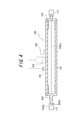
- FIG. 4 is a view showing a state of the roller 100 for an image forming apparatus in which resin shaft end flanges 102 and 103 are fitted to both ends of the hollow metal sleeve 101.
- a D-cut portion is formed on the tip side of the shaft portion 102a of the resin shaft end flange 102 on one side (left side in FIG. 4). It is easy to collapse.
- the shaft portion 102a of the image forming apparatus roller 100 is tilted, the image forming apparatus roller 100 is supported and rotated by the bearing 111 and the bearing 112 of the rotating device (the whole is not shown here).
- the shaft center 101CL of the metal sleeve 101 and the shaft center 102CL of the shaft portion 102a do not coincide with each other.
- the image forming apparatus roller 100 as described above may be subjected to a desired coating process on the outer peripheral surface of the metal sleeve 101 in the manufacturing process, for example, for chargeability control or surface protection.
- a state in which the metal sleeve 101 is coated is also shown.
- An image forming apparatus incorporating such a roller for an image forming apparatus having a coating with poor accuracy cannot form a clear image.
- the roller for the image forming apparatus in which the shaft is tilted may cause noise during rotation in the image forming apparatus, or may cause a conveyance failure when contacting the sheet material to be conveyed. There is also a case.
- the present invention is suitable for a roller for an image forming apparatus constituted by using a metal sleeve and a resin shaft end flange fitted to the end thereof, and the resin shaft without the shaft collapse as described above. It aims at proposing the metal mold
- mold an end flange. Another object of the present invention is to propose a highly reliable roller for an image forming apparatus that does not collapse.
- the resin shaft end flange mold of the present invention is fitted to the end portion of the metal sleeve of the roller for the image forming apparatus, and the shaft is erected at the axial center position of the flange portion.
- the shaft portion forming cavity has an inner surface formed so that a cross-sectional shape of the shaft portion has an n-order rotational symmetry around the shaft center (where n is an integer of 2 or more). It is characterized by that.
- the inner surface of the shaft portion forming cavity is formed so that the cross-sectional shape of the shaft portion is a square shape that is a multiple of three.
- the image forming apparatus roller of the present invention is an image forming apparatus roller formed by fitting a resin shaft end flange to an end portion of a metal sleeve, and the resin shaft end described above. It is characterized in that it is formed by using a resin shaft end flange formed by using a flange mold.
- the shaft section formed by using the metal mold is axial so that the cross-sectional shape has an n-order rotational symmetry around the axis (where n is an integer of 2 or more). Since the inner surface of the partial molding cavity is formed, the resin material is uniformly poured into the mold. Further, even if the internal stress is generated when the resin is subsequently cured in the mold, the generated internal stress is made uniform. Therefore, it is possible to mold a resin shaft end flange having a shaft portion that does not collapse. By adopting such a resin shaft end flange, it is possible to provide a highly reliable roller for an image forming apparatus whose axial center coincides with the metal sleeve side.
- FIG. 1A and 1B are views showing a mold for molding a resin shaft end flange according to an embodiment of the present invention, in which FIG. 1A is a sectional view in plan view, and FIG. FIG. (A)-(c) is the figure shown about the modification of the cross-sectional shape of a shaft part. It is sectional drawing shown in order to demonstrate the problem of the roller for conventional image forming apparatuses.
- FIG. 1 is a view showing an image forming apparatus roller 1 in which a resin shaft end flange formed by a mold according to the present invention is applied to one end (left side in FIG. 1).
- the image forming apparatus roller 1 includes a metal sleeve 2 formed by forming a metal in a cylindrical shape, and resin shaft end flanges 3 and 4 fitted in openings at both ends of the metal sleeve 2.
- the resin shaft end flange formed by the mold according to the present invention is used as the left resin shaft end flange 3 in FIG. 1.
- the resin material used for the resin shaft end flanges 3 and 4 may be appropriately selected from general-purpose resins and engineering plastics, and a resin material that can be easily molded by injection molding or the like is selected. It is preferable to do this.
- an engineering plastic that can be used as a material (resin material) of a resin shaft end flange
- polyacetal polyamide resin (for example, polyamide 6, polyamide 6/6, polyamide 12, polyamide 4/6, polyamide) 6.10, polyamide 6.12, polyamide 11, polyamide MXD6 (polyamide obtained from metaxylenediamine and adipic acid), polyoxymethylene (POM), polybutylene terephthalate, polyphenylene oxide, polyphenylene ether, polyphenylene sulfide, Polyethersulfone, polycarbonate, polyimide, polyamideimide, polyetherimide, polysulfone, polyetheretherketone, polyethylene terephthalate, polyarylate It may include a liquid crystal polymer, polytetrafluoroethylene and the like.
- the general-purpose resin examples include polypropylene, acrylonitrile-butadiene-styrene (ABS) resin, polystyrene, and polyethylene.
- ABS acrylonitrile-butadiene-styrene
- a melamine resin, a phenol resin, a silicone resin, or the like can be used as the resin material. These may be used individually by 1 type and may be used in combination of 2 or more type.
- the resin material engineering plastic is preferable, and in particular, polyacetal, polyamide resin, polybutylene terephthalate, polyphenylene ether, polyphenylene sulfide, polycarbonate, and the like have thermoplasticity, excellent moldability, and mechanical properties. It is more preferable in terms of excellent strength.
- the resin material polyamide 6 ⁇ 6, polyamide MXD6, polyamide 6 ⁇ 12, polybutylene terephthalate, or a mixed resin thereof is preferable.
- the conductive agent in the case where the resin shaft end flange is provided with conductivity various materials can be used as long as they can be uniformly dispersed in the resin material. Specifically, carbon black powder, graphite powder, carbon fiber, metal powder such as aluminum, copper and nickel, metal oxide powder such as tin oxide, titanium oxide and zinc oxide, and powder such as conductive glass powder A conductive agent is preferably used. These may be used individually by 1 type and may be used in combination of 2 or more type.
- the basic configuration as described above is the same as that of a conventional resin shaft end flange, but the resin shaft end flange 3 (located on the left side in FIG. 1) employed in the image forming apparatus roller 1 is It is characterized in that it is molded using a mold described later.
- the resin shaft end flange 3 includes a flange portion 3FL in which a part thereof is fitted in the metal sleeve 2 and a shaft portion 3AX provided upright at the axial center position.
- the flange portion 3FL has a cylindrical fitting portion that has an outer diameter substantially equal to the inner diameter of the cylindrical metal sleeve 2 and is fitted to the inner peripheral surface of the metal sleeve 2, and the fitting portion.
- a disc-shaped closing portion that closes the end of the metal sleeve 2 when the metal sleeve 2 is fitted to the fitting portion.
- the shaft portion 3AX is erected at the center position of the disc-shaped closing portion toward the side opposite to the fitting portion.
- a notch is formed on the tip end side of the shaft portion 3AX in the same manner as a conventional image forming apparatus roller.
- the cross-sectional shape of the shaft portion 3AX in which the notch is formed is not a D-cut shape as in the prior art, but a shape having rotational symmetry around the axis center (where n is an integer of 2 or more). It has become.
- n is an integer of 2 or more.
- rotational symmetry means symmetry that coincides with the original figure when the shaft portion is rotated around the axis, and for example, a shape having secondary rotational symmetry is obtained by rotating the shaft by 180 degrees. Sometimes the same shape.
- shape having third-order rotational symmetry is a shape that becomes the same shape when the shaft is rotated 120 degrees.
- the shape having fourth-order rotational symmetry is a shape that becomes the same shape when the shaft is rotated 90 degrees.
- the D-cut portion is formed in the shaft portion when the outer peripheral surface of the sleeve is coated in the manufacturing process of the roller for the image forming apparatus, or for the image forming apparatus in the image forming apparatus.
- the fitting portion of the conventional image forming apparatus and the coating apparatus that fits the shaft portion of the conventional image forming apparatus roller has a shape corresponding to the D-cut portion of the conventional image forming apparatus roller (D-shaped). I was doing.
- the tip portion of the shaft portion 3AX in FIG. 1 may be designed as a structure in which a plurality of D-cut portions are arranged so as to have rotational symmetry. In other words, two D-cut parts are arranged if it has second-order rotational symmetry, and three D-cut parts are arranged if it has third-order rotational symmetry, and one of the D-cut parts is painted. What is necessary is just to make it fit with the fitting part of an apparatus and the fitting part of an image forming apparatus. In this way, it is not necessary to change the fitting portion of the conventional coating apparatus or image forming apparatus in which the conventional image forming apparatus roller is set.
- the present inventor has confirmed that if the notches formed in the shaft portion are arranged symmetrically, it is possible to prevent the shaft from collapsing even with a flange formed by resin molding with a mold. That is, in the prior art, only one D-cut portion was formed from the idea that only one cut-out is required for fitting with a coating apparatus or an image forming apparatus.
- the non-rotationally symmetric shape has been achieved by recognizing that this is an unfavorable structure for a resin shaft end flange molded by a mold.
- FIG. 2 is a view showing a mold for forming the resin shaft end flange according to an embodiment of the present invention, wherein (a) is a sectional view in plan view, and (b) is a cross-sectional view of (a). It is a bb arrow line view.
- This resin shaft end flange mold 10 is provided with a flange portion forming die 11 provided with a flange portion forming cavity 12 for forming a flange portion, and a shaft portion forming cavity 16 for forming a shaft portion. It is comprised by arrange
- a resin injection gate 13 is formed on the shaft mold 15 side.
- the flange portion forming cavity 12 has an inner surface in the shape of a recess for forming the flange portion 3FL of the main body partly fitted to the metal sleeve 2.
- the flange portion forming cavity 12 includes a cylindrical recessed space having an outer diameter substantially equal to the inner diameter of the metal sleeve 2 and one end side of the cylindrical recessed space (joining surface with the shaft forming die 15). And a disk-shaped recessed space having a diameter substantially equal to the outer diameter of the metal sleeve 2.
- the inner surface of the shaft portion forming cavity 16 is formed in a concave shape for forming the shaft portion standing at the shaft center position of the flange portion 3FL.
- the shaft portion molding cavity 16 is formed at a cylindrical recess space formed on the joint surface side with the flange portion mold 11 and at the tip (left side in FIG. 2) of the cylindrical recess space.
- the cross-sectional shape in the direction orthogonal to the axis is constituted by a recessed space having n-th order rotational symmetry.
- the resin injection gate 13 communicates with the recess space having the nth-order rotational symmetry.
- the tip side portion 16TP of the shaft portion molding cavity 16 has a shaft portion in which the cross-sectional shape of the resin material filled therein has an n-th order (n is an integer of 2 or more) rotational symmetry about the axis.
- the shape of the inner surface is designed to be a shape.
- FIG. 2B illustrates a case where a shaft portion having third-order rotational symmetry is formed around the axis 16CL.
- the resin-made shaft end flange without a shaft fall in a shaft part can be manufactured. That is, as shown in FIG. 2, the shaft portion is molded so that the inner surface is formed so that the cross section has an n-th order (where n is an integer of 2 or more) rotational symmetry around the axis.
- n is an integer of 2 or more
- the resin shaft end flange formed using the mold has a shape corresponding to the shaft portion forming cavity, that is, a shape having n-order rotation objectability.
- the shaft portion molding cavity only needs to have a shape in which the cross-sectional shape of the tip of the shaft portion molded by the shaft portion molding cavity has n-order rotational symmetry about the axis. That is, for example, the shape may be the same shape when rotated 180 degrees in the second order, and the same shape when rotated 90 degrees in the fourth order.
- the D-cut portion is originally provided is that the positioning of the roller for the image forming apparatus and the reliable transmission of the driving force are intended, so that one side is somewhat long (with the fitting portion of the image forming apparatus or the coating apparatus). It is desirable that the contact allowance is large to some extent. Therefore, as shown in FIG. 2B, it is preferable that the cross-sectional shape of the shaft portion is a triangle (the D-cut portion has three surfaces).
- the “square shape” includes a shape with rounded vertices as shown in FIG.
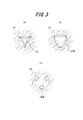
- FIGS. 3A to 3C are diagrams showing modifications of the cross-sectional shape of the shaft portion.
- the cross-sectional shape is not necessarily a square shape connected by a straight line, and may be changed to a square shape connected by a curve.
- it is preferable to use the third order (n 3) as illustrated in FIG.
- FIG. 3 (a) shows a shape in which the tip end portion 16TP of the cavity on the shaft portion forming die 15 side is changed to a curved line convex on the inside of the triangle, with the straight portions (each side) being based on the triangle.
- b) shows a shape in which the straight line portion is changed to a convex curve outward of the triangle. Furthermore, as shown in FIG.
- groove-shaped concave portions 16CP are provided at intervals of 120 degrees in the circumferential direction (shape having rotational symmetry) may be employed.
- shape having rotational symmetry it may be necessary to modify the fitting portion of the coating apparatus or the image forming apparatus.
- the resin shaft end flange 4 set on the other end (right side in FIG. 1) of the roller for the image forming apparatus a conventional mold having a simple cavity having no notch in the shaft portion is used. What is necessary is just to shape
- the roller 1 for an image forming apparatus of the above example only the resin shaft end flange 3 on the side that is fitted to the fitting portion on the drive source side of the image forming apparatus or the coating apparatus is shown, and the cross section of the shaft portion is the axial center.
- the shape has n-order rotational symmetry around.
- the resin shaft end flange on the other end side may have a shape in which the cross section of the shaft portion has n-order rotational symmetry around the axis.
- a roller for an image forming apparatus (see FIG. 1) in which a resin shaft end flange manufactured using the mold shown in FIG. 2 was fitted to the end portion was manufactured.
- a roller for an image forming apparatus is formed by fitting resin-made shaft end flanges to both ends of a metal sleeve made of aluminum (manufactured by Nikkin Gold Co., Ltd., aluminum A6063).
- a thermoplastic resin for forming the resin shaft end flange a conductive material (manufactured by Polyplastics Co., Ltd., EB-10) was used. Further, the metal sleeve and the resin shaft end flange were bonded using an adhesive (manufactured by Loctite Co., Ltd., 430).
- the roller for the image forming apparatus has a body length BL of 230 mm including the metal sleeve 2 up to the flange portion 3FL of the resin shaft end flange 3, and the resin shaft end flange 3 protrudes from the flange portion 3FL.
- the shaft length 3L of the shaft portion 3AX to be formed was set to 30 mm, and the shaft length 4L of the shaft portion protruding from the flange portion of the opposite resin shaft end flange 4 was set to 15 mm.
- rollers for an image forming apparatus using a resin shaft end flange manufactured with the mold shown in FIG. 2 were prepared as examples.
- seven comparative image forming roller rollers were prepared in the same manner as in the example except that a conventional resin shaft end flange having only one D-cut portion was used. Then, as shown by taking out the resin shaft end flange 3 in FIG. 1, the deflection of the shaft tip A with respect to the portion (reference portion B point) press-fitted into the sleeve 2 was measured.
- the runout of the point A with respect to the B point was measured.
- This measurement was performed by measuring the misalignment (concentricity) of the shaft tip portion A point with respect to the reference portion B point with a roundness measuring device LONDCOM 41A manufactured by Tokyo Seimitsu Co., Ltd. The unit is mm. Further, the deflection at the center C of the main body (metal sleeve 2) was measured with the shafts at both ends supported. This measurement was carried out by measuring the vibration with a laser vibration measuring instrument LSM-6000 manufactured by Mitutoyo Co., Ltd. The unit is mm. Then, an image formed by setting each roller in the image forming apparatus was evaluated.
- the resin shaft end flange mold according to the present invention can prevent the shaft from collapsing and manufacture the resin shaft end flange.
- a roller for an image forming apparatus having a resin shaft end flange the axial center of the sleeve portion and the flange portion coincide with each other, so that a reliable image can be formed without causing problems such as rotational vibration and noise generation. It can be supplied as a roller for an image forming apparatus having high performance.
- such a roller for an image forming apparatus can form a uniform coating film in the painting process, this point also contributes to obtaining a clear image formation.
- a resin shaft end flange which is suitable for a roller for an image forming apparatus configured using a metal sleeve and a resin shaft end flange fitted to the end portion thereof and which does not fall down is formed.
- a mold can be provided.
Landscapes
- Engineering & Computer Science (AREA)
- Physics & Mathematics (AREA)
- General Physics & Mathematics (AREA)
- Mechanical Engineering (AREA)
- Manufacturing & Machinery (AREA)
- General Engineering & Computer Science (AREA)
- Plasma & Fusion (AREA)
- Rolls And Other Rotary Bodies (AREA)
- Moulds For Moulding Plastics Or The Like (AREA)
- Electrophotography Configuration And Component (AREA)
Abstract
Description
このように、金属製の中実の棒体を削り加工すれば、精度良く加工することができるので、軸精度の良好な画像形成装置用ローラを得ることができる。また、ローラの軸端部をDカット加工しておけば、ローラを画像形成装置内にセットするときの位置決めにDカット部分を利用できると共に、Dカット部分にギアを嵌め込んでモータ(駆動源)の動力を伝達し、ローラの回転駆動を円滑に行うこともできる。更に、画像形成装置用ローラの本体胴部を塗装して被膜を形成する被膜形成工程などでも、位置決めや駆動力の伝達等にDカット部分を活用できる。
そして、特許文献4で開示する画像形成装置用ローラによれば、中空の金属スリーブの両端に樹脂製軸端フランジを固定してローラを形成しているので、ローラを軽量化することができると共に、使用する金属量を削減してコスト低減を図ることができる。
この図4で示す画像形成装置用ローラ100では、片側(図4では左方)の樹脂製軸端フランジ102の軸部102aの先端側にDカット部分が形成されており、軸部102aが軸倒れし易い。そして、画像形成装置用ローラ100の軸部102aが軸倒れしていた場合、回転装置(ここでは、全体を図示しない)の軸受111と軸受112とで画像形成装置用ローラ100を支持して回転させたときに、金属スリーブ101の軸心101CLと、軸部102aの軸心102CLとが一致していないので回転振れが発生してしまう。
なお、上述したような画像形成装置用ローラ100には、例えば帯電性の制御や表面保護のために、製造工程で金属スリーブ101の外周面に所望の塗装処理がされる場合がある。
図4で示した状態で、軸倒れにより回転振れが発生すると、塗装した膜厚が不均一になり、精度の悪い塗装になってしまう。そして、このような精度の悪い塗装を有する画像形成装置用ローラを組込んだ画像形成装置は、鮮明な画像を形成することができなくなる。また、軸倒れが発生している画像形成装置用ローラは、画像形成装置内で、回転時に騒音を発生させたり、搬送されるシート材との接触したときの搬送不良を発生させる原因となったりする場合もある。
ここで、本発明の樹脂製軸端フランジ用金型は、画像形成装置用ローラの金属スリーブの端部に嵌合される、フランジ部と該フランジ部の軸中心位置に立設されている軸部とを備えた樹脂製軸端フランジを成形するための金型であって、
前記フランジ部を形成するためのフランジ部成形キャビティと、前記軸部を形成するための軸部成形キャビティとを備えており、
前記軸部成形キャビティは、前記軸部の横断面形状が軸心回りにn次(ただし、nは2以上の整数)の回転対称性をもった形状となるように、その内面が形成してある、ことを特徴とする。
本発明の理解を容易とするため、先ず、本発明に係る金型によって成形した樹脂製軸端フランジが適用された画像形成装置用ローラの概略を説明する。
図1は、本発明に係る金型によって成形した樹脂製軸端フランジが端部の一方(図1では左側)に適用された画像形成装置用ローラ1について示した図である。この画像形成装置用ローラ1は金属を円筒状に形成してなる金属スリーブ2と、この金属スリーブ2の両端の開口に嵌合される樹脂製軸端フランジ3、4とによって構成されている。そして、この画像形成装置用ローラ1では、図1では左側の樹脂製軸端フランジ3として、本発明に係る金型によって成形した樹脂製軸端フランジを用いている。
上述したような基本的な構成については、従来の樹脂製軸端フランジと同様であるが、画像形成装置用ローラ1で採用されている樹脂製軸端フランジ3(図1では左側に配置)は、後述する金型を用いて成形したものである点に特徴がある。
ここで、この軸部3AXの先端部側には、従来の画像形成装置用ローラと同様に切欠きが形成してある。ただし、切欠きが形成された軸部3AXの横断面形状は、従来のようなDカット形状ではなく、軸心回りにn次(ただし、nは2以上の整数)の回転対称性をもつ形状となっている。このように、回転対称性をもつ形状としておくと、金型に樹脂材料を流し込んで樹脂製軸端フランジ3を形成しても、先に指摘したような軸部3AXの軸倒れの発生を防止できる。
なお、「回転対称性」とは軸部を軸心回りに回転させたときに元の図形と一致する対称性で、例えば2次の回転対称性を有する形状とは、軸を180度回転したときに同一形状となる形状である。同様に、3次の回転対称性を有する形状とは、軸を120度回転したときに、同一形状となる形状である。また、4次の回転対称性を有する形状とは、軸を90度回転したときに同一形状となる形状である。
上記に対して、本発明者は、軸部に形成する切欠きを対称性をもって配置しておくと、金型で樹脂成型したフランジでも軸倒れを防止できることを確認して本発明に至った。即ち、従来にあっては、塗装装置や画像形成装置に嵌合するために1箇所だけ切欠いてあればよいという発想からDカット部分を1箇所だけ形成していたが、このような不均一(非回転対称)形状は金型で成形する樹脂製軸端フランジには不利な構造であることを認識したこと基づいて、本発明に至ったものである。
この樹脂製軸端フランジ用金型10は、フランジ部を形成するためのフランジ部成形キャビティ12が設けられているフランジ部成形型11と、軸部を形成するための軸部成形キャビティ16が設けられている軸部成形型15とを隣接配置することにより構成されている。そして、軸部成形型15側には、樹脂注入ゲート13が形成されている。
フランジ部成形キャビティ12は、金属スリーブ2に一部が嵌合される本体のフランジ部3FLを成形する凹部状に内面が形成されている。具体的には、フランジ部形成キャビティ12は、金属スリーブ2の内径に略等しい外径を有する円筒状の凹部空間と、該円筒状の凹部空間の一端側(軸部成形型15との接合面側)に形成された、金属スリーブ2の外径と略等しい直径を有する円板状の凹部空間とで構成されている。同様に、軸部成形キャビティ16も、フランジ部3FLの軸中心位置に立設されている軸部を成形する凹部状に内面が形成されている。具体的には、軸部成形キャビティ16は、フランジ部成形型11との接合面側に形成された円柱状の凹部空間と、該円柱状の凹部空間の先端(図2では左側)に形成された、軸線と直交する方向の横断面形状がn次の回転対称性を有する凹部空間とで構成されている。そして、n次の回転対称性を有する凹部空間には、樹脂注入ゲート13が連通している。
なお、図2(b)では、軸心16CL回りに3次の回転対称性を持つ軸部を形成する場合を例示している。このように軸部に形成される切欠きが軸心回りに対称性をもつように設定すると、図から明らかなように樹脂注入ゲート13から均一に樹脂材料が流し込まれ、更にその後に樹脂材料が硬化したときに内部応力が発生しても、発生した内部応力の均一化を図ることができる。これにより、軸部に軸倒れのない樹脂製軸端フランジを製造することができる。
すなわち、図2で例示するような、横断面が軸心回りにn次(ただし、nは2以上の整数)の回転対称性をもった形状となるように内面が形成してある軸部成形キャビティを備えた金型を用いることにより、軸倒れのない樹脂製軸端フランジを製造することができる。そして、該金型を用いて成形した樹脂製軸端フランジは、軸部が軸部成形キャビティに対応した形状となる、即ち、n次の回転対象性をもった形状となる。
ただし、n次の数字が増すと、軸部の横断面形状が円に近くなる。また、そもそもDカット部分を設けていた理由は、画像形成装置用ローラの位置決めや駆動力の確実な伝達が目的であるので、一辺がある程度長い(画像形成装置や塗装装置の嵌合部との接触代(しろ)がある程度大きい)ことが望ましい。よって、図2(b)で示すように軸部の横断面形状を三角形(Dカット部分が3面)とするのが好ましい。
なお、「角形状」には、図2(b)に示すように、頂点が丸まった形状も含まれる。
図3(a)は、軸部成形型15側のキャビティの先端側部分16TPを、三角形を基本として直線部分(各辺)を三角形の内側へ凸の曲線に変更した形状について示し、図3(b)は、直線部分を三角形の外側へ凸の曲線に変更した形状について示している。さらには、図3(c)示すように、周方向へ120度の間隔で溝状の凹部16CPを設けた形状(回転対称性をもった形状)とした変形例としてもよい。ただし、図3で例示する形状を採用するには、塗装装置や画像形成装置の嵌合部に修正を加えることが必要となる場合がある。
因みに、上記一例の画像形成装置用ローラ1では、画像形成装置や塗装装置の駆動源側の嵌合部に嵌合する側の樹脂製軸端フランジ3のみを、軸部の横断面が軸心回りにn次の回転対称性をもった形状とした。しかし、本発明の画像形成装置用ローラでは、他端側の樹脂製軸端フランジも、軸部の横断面が軸心回りにn次の回転対称性をもった形状としても良い。
図2で示す金型を用いて製造した樹脂製軸端フランジを端部に嵌合した画像形成装置用ローラ(図1参照)を製造した。ここでは、アルミニウム製(日軽金(株)製、アルミA6063)の金属スリーブの両端に樹脂製軸端フランジを嵌合して画像形成装置用ローラとした。樹脂製軸端フランジを形成する熱可塑性樹脂として導電性材料(ポリプラスチック(株)製、 EB-10)を用いた。また、金属スリーブと樹脂製軸端フランジとは、接着剤(ロックタイト(株)製、430)を用いて接着した。
また、両端の軸部を支持した状態で本体(金属スリーブ2)中央のC点の振れを測定した。この測定は、両端軸部を直径(φ)24mmのベアリング2個で受けて回転させ、(株)ミツトヨ製のレーザー振れ測定器LSM-6000にて振れを測定することで実施した。単位はmmである。
そして、各ローラを画像形成装置にセットして形成される画像を評価した。印字された画像について、画像不良(画像ムラの発生)を生じない場合を「○」、画像不良がやや生じた場合を「△」、そして、明らかに画像不良を生じた場合を「×」として評価した。
さらに、回転時騒音についても併せて評価した。回転時の騒音が発生しない場合には「○」、騒音が発生する場合には「×」とした。
7つの実施例および7つの比較例の評価結果をまとめたのが下記表1である。

また、このような画像形成装置用ローラは、塗装工程で均一な塗膜を形成できるので、この点でも鮮明な画像形成を得ることについて寄与することになる。
2 金属スリーブ
3、4 樹脂製軸端フランジ
10 樹脂製軸端フランジ用金型
12 フランジ部成形キャビティ
16 軸部成形キャビティ
Claims (3)
- 画像形成装置用ローラの金属スリーブの端部に嵌合される、フランジ部と該フランジ部の軸中心位置に立設されている軸部とを備えた樹脂製軸端フランジを成形するための金型であって、
前記フランジ部を形成するためのフランジ部成形キャビティと、前記軸部を形成するための軸部成形キャビティとを備えており、
前記軸部成形キャビティは、前記軸部の横断面形状が軸心回りにn次(ただし、nは2以上の整数)の回転対称性をもった形状となるように、その内面が形成してある、ことを特徴とする樹脂製軸端フランジ用金型。 - 前記軸部成形キャビティは、前記軸部の横断面形状が3の倍数の角形状となるように、その内面が形成してある、ことを特徴とする請求項1に記載の樹脂製軸端フランジ用金型。
- 金属スリーブの端部に、樹脂製軸端フランジを嵌合して形成されている画像形成装置用ローラであって、
請求項1または2に記載の樹脂製軸端フランジ用金型を用いて成形した樹脂製軸端フランジを用いている、ことを特徴とする画像形成装置用ローラ。
Priority Applications (2)
| Application Number | Priority Date | Filing Date | Title |
|---|---|---|---|
| CN201180022556.5A CN102883864B (zh) | 2010-03-30 | 2011-03-29 | 用于树脂制轴端凸缘的模具和用于图像形成装置的包括由该模具生产的树脂制轴端凸缘的辊 |
| US13/638,444 US20130051858A1 (en) | 2010-03-30 | 2011-03-29 | Mold for resin shaft-end flange and roller for image forming device including the resin shaft-end flange produced by the mold |
Applications Claiming Priority (2)
| Application Number | Priority Date | Filing Date | Title |
|---|---|---|---|
| JP2010079346A JP5713577B2 (ja) | 2010-03-30 | 2010-03-30 | 樹脂製軸端フランジ用金型、この金型を用いて成形した樹脂製軸端フランジを用いたoaローラ |
| JP2010-079346 | 2010-03-30 |
Publications (1)
| Publication Number | Publication Date |
|---|---|
| WO2011122009A1 true WO2011122009A1 (ja) | 2011-10-06 |
Family
ID=44711765
Family Applications (1)
| Application Number | Title | Priority Date | Filing Date |
|---|---|---|---|
| PCT/JP2011/001877 Ceased WO2011122009A1 (ja) | 2010-03-30 | 2011-03-29 | 樹脂製軸端フランジ用金型、この金型を用いて成形した樹脂製軸端フランジを用いた画像形成装置用ローラ |
Country Status (4)
| Country | Link |
|---|---|
| US (1) | US20130051858A1 (ja) |
| JP (1) | JP5713577B2 (ja) |
| CN (1) | CN102883864B (ja) |
| WO (1) | WO2011122009A1 (ja) |
Families Citing this family (2)
| Publication number | Priority date | Publication date | Assignee | Title |
|---|---|---|---|---|
| JP6818416B2 (ja) * | 2016-02-18 | 2021-01-20 | キヤノン株式会社 | カートリッジ、及び画像形成装置 |
| JP6841084B2 (ja) * | 2017-02-27 | 2021-03-10 | 富士ゼロックス株式会社 | ロールユニット及び画像形成装置 |
Citations (3)
| Publication number | Priority date | Publication date | Assignee | Title |
|---|---|---|---|---|
| JP2002328585A (ja) * | 2001-04-27 | 2002-11-15 | Canon Inc | プロセスカートリッジ |
| JP2006023700A (ja) * | 2004-06-09 | 2006-01-26 | Bridgestone Corp | 現像ローラおよびそれを用いた画像形成装置 |
| JP2008151324A (ja) * | 2006-12-20 | 2008-07-03 | Bridgestone Corp | Oaローラ用中空回転体 |
Family Cites Families (9)
| Publication number | Priority date | Publication date | Assignee | Title |
|---|---|---|---|---|
| US2395147A (en) * | 1943-02-13 | 1946-02-19 | Conveyor Company | Weatherproof roller construction |
| JP2539278Y2 (ja) * | 1991-05-01 | 1997-06-25 | 住友重機械工業株式会社 | スクリュウコンベヤ |
| JPH11153129A (ja) * | 1997-08-12 | 1999-06-08 | Ricoh Co Ltd | 円筒状構造体、該円筒状構造体の製造方法、及び、該製造方法に用いるスリーブのかしめ装置、並びに、現像ローラ、該現像ローラの製造方法、及び、現像装置 |
| US5970294A (en) * | 1997-08-12 | 1999-10-19 | Ricoh Company, Ltd. | Cylindrical structural body for use in an image forming apparatus and method of producing the same |
| EP1630625A4 (en) * | 2003-05-22 | 2012-10-03 | Mitsubishi Chem Corp | PHOTOSENSITIVE BODY DRUM, METHOD AND DEVICE FOR ASSEMBLING THE SAME, AND IMAGE FORMING DEVICE USING THE DRUM |
| JP2005156654A (ja) * | 2003-11-21 | 2005-06-16 | Canon Inc | 帯電装置、プロセスカートリッジおよび画像形成装置 |
| US8292791B2 (en) * | 2005-04-07 | 2012-10-23 | Bridgestone Corporation | Electrical conductive roller |
| JP2008116868A (ja) * | 2006-11-08 | 2008-05-22 | Kaneka Corp | マグネットローラ |
| JP2008260216A (ja) * | 2007-04-12 | 2008-10-30 | Canon Chemicals Inc | 成形金型、弾性ロール及びその製造方法、電子写真プロセスカートリッジ並びに画像形成装置 |
-
2010
- 2010-03-30 JP JP2010079346A patent/JP5713577B2/ja not_active Expired - Fee Related
-
2011
- 2011-03-29 CN CN201180022556.5A patent/CN102883864B/zh not_active Expired - Fee Related
- 2011-03-29 WO PCT/JP2011/001877 patent/WO2011122009A1/ja not_active Ceased
- 2011-03-29 US US13/638,444 patent/US20130051858A1/en not_active Abandoned
Patent Citations (3)
| Publication number | Priority date | Publication date | Assignee | Title |
|---|---|---|---|---|
| JP2002328585A (ja) * | 2001-04-27 | 2002-11-15 | Canon Inc | プロセスカートリッジ |
| JP2006023700A (ja) * | 2004-06-09 | 2006-01-26 | Bridgestone Corp | 現像ローラおよびそれを用いた画像形成装置 |
| JP2008151324A (ja) * | 2006-12-20 | 2008-07-03 | Bridgestone Corp | Oaローラ用中空回転体 |
Also Published As
| Publication number | Publication date |
|---|---|
| JP2011207164A (ja) | 2011-10-20 |
| CN102883864B (zh) | 2015-02-25 |
| US20130051858A1 (en) | 2013-02-28 |
| JP5713577B2 (ja) | 2015-05-07 |
| CN102883864A (zh) | 2013-01-16 |
Similar Documents
| Publication | Publication Date | Title |
|---|---|---|
| WO2011122009A1 (ja) | 樹脂製軸端フランジ用金型、この金型を用いて成形した樹脂製軸端フランジを用いた画像形成装置用ローラ | |
| JP2001056020A (ja) | 断熱スリーブ、定着ローラ用軸受装置および定着装置 | |
| CN1955852B (zh) | 导电辊 | |
| JP2004151616A (ja) | 導電ローラおよびそれを用いた画像形成装置 | |
| JP4939914B2 (ja) | Oaローラ用中空回転体 | |
| JPH11153129A (ja) | 円筒状構造体、該円筒状構造体の製造方法、及び、該製造方法に用いるスリーブのかしめ装置、並びに、現像ローラ、該現像ローラの製造方法、及び、現像装置 | |
| JP5726712B2 (ja) | 成形金型及びローラ製造方法 | |
| JP2006105375A (ja) | 導電性ローラおよびその製造方法 | |
| JPH0247680A (ja) | 現像ローラ | |
| JP5224501B2 (ja) | 成形金型及びローラの製造方法 | |
| JP2008119849A (ja) | 樹脂中空成型品の製造方法 | |
| JP2555090Y2 (ja) | マグネット装置 | |
| JP4038632B2 (ja) | 感光ドラム用基体の製造方法 | |
| JP2007248814A (ja) | 導電性ローラ | |
| JP4166034B2 (ja) | ゴムローラ | |
| JP2007047624A (ja) | 導電性ローラおよびその製造方法 | |
| JP2006251004A (ja) | 導電性ローラおよびそれを用いた画像形成装置 | |
| JP2008122460A (ja) | 導電性ローラ | |
| JP2008233564A (ja) | 現像ローラの製造方法 | |
| JP2000056621A (ja) | 電子写真感光体用フランジ | |
| JP2006138375A (ja) | トルクリミッタおよびその製造方法 | |
| JP2002316340A (ja) | 感光ドラム用基体成形金型、感光ドラム用基体の製造方法及び感光ドラム用基体並びに感光ドラム | |
| JP2006251035A (ja) | 導電性ローラおよびそれを用いた画像形成装置 | |
| JP2001154489A (ja) | 磁性現像ローラ及びそれを用いた画像形成装置 | |
| JP2001254872A (ja) | 樹脂パイプ及び感光ドラム |
Legal Events
| Date | Code | Title | Description |
|---|---|---|---|
| WWE | Wipo information: entry into national phase |
Ref document number: 201180022556.5 Country of ref document: CN |
|
| 121 | Ep: the epo has been informed by wipo that ep was designated in this application |
Ref document number: 11762253 Country of ref document: EP Kind code of ref document: A1 |
|
| NENP | Non-entry into the national phase |
Ref country code: DE |
|
| WWE | Wipo information: entry into national phase |
Ref document number: 13638444 Country of ref document: US |
|
| 122 | Ep: pct application non-entry in european phase |
Ref document number: 11762253 Country of ref document: EP Kind code of ref document: A1 |