WO2011121934A1 - 実装ライン電力制御装置及び実装ライン電力制御方法 - Google Patents
実装ライン電力制御装置及び実装ライン電力制御方法 Download PDFInfo
- Publication number
- WO2011121934A1 WO2011121934A1 PCT/JP2011/001669 JP2011001669W WO2011121934A1 WO 2011121934 A1 WO2011121934 A1 WO 2011121934A1 JP 2011001669 W JP2011001669 W JP 2011001669W WO 2011121934 A1 WO2011121934 A1 WO 2011121934A1
- Authority
- WO
- WIPO (PCT)
- Prior art keywords
- power
- mounting line
- mounting
- period
- target value
- Prior art date
- Legal status (The legal status is an assumption and is not a legal conclusion. Google has not performed a legal analysis and makes no representation as to the accuracy of the status listed.)
- Ceased
Links
Images





Classifications
-
- H—ELECTRICITY
- H05—ELECTRIC TECHNIQUES NOT OTHERWISE PROVIDED FOR
- H05K—PRINTED CIRCUITS; CASINGS OR CONSTRUCTIONAL DETAILS OF ELECTRIC APPARATUS; MANUFACTURE OF ASSEMBLAGES OF ELECTRICAL COMPONENTS
- H05K13/00—Apparatus or processes specially adapted for manufacturing or adjusting assemblages of electric components
- H05K13/08—Monitoring manufacture of assemblages
-
- H—ELECTRICITY
- H05—ELECTRIC TECHNIQUES NOT OTHERWISE PROVIDED FOR
- H05K—PRINTED CIRCUITS; CASINGS OR CONSTRUCTIONAL DETAILS OF ELECTRIC APPARATUS; MANUFACTURE OF ASSEMBLAGES OF ELECTRICAL COMPONENTS
- H05K13/00—Apparatus or processes specially adapted for manufacturing or adjusting assemblages of electric components
-
- H—ELECTRICITY
- H05—ELECTRIC TECHNIQUES NOT OTHERWISE PROVIDED FOR
- H05K—PRINTED CIRCUITS; CASINGS OR CONSTRUCTIONAL DETAILS OF ELECTRIC APPARATUS; MANUFACTURE OF ASSEMBLAGES OF ELECTRICAL COMPONENTS
- H05K13/00—Apparatus or processes specially adapted for manufacturing or adjusting assemblages of electric components
- H05K13/04—Mounting of components, e.g. of leadless components
-
- H—ELECTRICITY
- H05—ELECTRIC TECHNIQUES NOT OTHERWISE PROVIDED FOR
- H05K—PRINTED CIRCUITS; CASINGS OR CONSTRUCTIONAL DETAILS OF ELECTRIC APPARATUS; MANUFACTURE OF ASSEMBLAGES OF ELECTRICAL COMPONENTS
- H05K13/00—Apparatus or processes specially adapted for manufacturing or adjusting assemblages of electric components
- H05K13/08—Monitoring manufacture of assemblages
- H05K13/0885—Power supply
Definitions
- the present invention relates to a mounting line power control apparatus and a mounting line power control method for controlling the power used by a mounting line group including a plurality of mounting lines each having a mounting board production apparatus for producing a mounting board.
- a mounting line having a plurality of mounting board production apparatuses such as a component mounting apparatus for producing a mounting board is arranged. For this reason, the factory is equipped with many mounting board production apparatuses that use electric power, and much electric power is consumed.
- Patent Document 1 discloses an apparatus that monitors the power consumption in order to suppress an increase in power consumption of the mounting board production apparatus.
- Patent Document 2 discloses a device that suppresses an increase in power consumption by performing time difference control for air conditioning equipment, refrigeration equipment, lighting equipment, and the like.
- Patent Document 3 discloses an apparatus that performs control in consideration of power consumption by determining the number of beams used so that the target production time is not exceeded in a component mounting apparatus included in a mounting line.
- a plurality of mounting lines may be arranged in a factory that manufactures mounting boards in order to produce a plurality of mounting boards in parallel.
- the said conventional power control apparatus is not an apparatus for suppressing the increase in the electric power used in these whole some mounting lines.
- the device disclosed in Patent Document 2 is a device for controlling an increase in power consumption by controlling a single facility such as an air conditioning facility, a refrigeration facility, or a lighting facility.
- the device disclosed in Patent Document 3 is a device for suppressing an increase in power consumption of a mounting board production apparatus in one mounting line.
- the device disclosed in Patent Document 1 is a device that monitors power usage, and is not a device for suppressing an increase in power usage.
- the conventional power control device is not a device for suppressing an increase in power consumption in the entire plurality of mounting lines, and may not be able to efficiently suppress the increase in power consumption. There's a problem.
- the present invention has been made in view of such a problem, and a mounting line power control apparatus and a mounting line power control method capable of efficiently suppressing an increase in power consumption in a plurality of mounting lines as a whole.
- the purpose is to provide.
- a mounting line power control apparatus controls power used by a mounting line group including a plurality of mounting lines having a mounting board production apparatus for producing a mounting board on which components are mounted.
- a mounting line power control device for each of the mounting lines, a target value acquisition unit for acquiring a target value of demand power indicating the amount of power used in a first period, and priority for using the power for each mounting line Included in the mounting line group when the demand power in the first period of the first mounting line included in the mounting line group exceeds a target value.
- a target value changing unit for reducing a target value of demand power in the first period of the second mounting line having the first priority lower than the first mounting line; and the first period of the second mounting line. As demand power does not exceed the target value after reduction, and a the use power changing unit to reduce power use in the first period of the second mounting board production apparatus mounting line has.
- the target value of the demand power of the second mounting line is reduced so as not to exceed the target value after the reduction.
- the power consumption of the mounting board production apparatus included in the second mounting line is reduced.
- the second mounting line includes a plurality of the mounting board production apparatuses
- the priority acquisition unit is a second priority that uses power for each of the mounting board production apparatuses.
- the power usage changing unit is configured to produce a plurality of mounting boards included in the second mounting line until the demand power in the first period of the second mounting line is equal to or less than a target value after reduction.
- the devices in order of decreasing second priority, determine a power reduction device that is a mounting board production device in which the power used in the first period is reduced, and in the determined first period of the power reduction device Use less power.
- the power reduction device includes a plurality of devices, and the power consumption changing unit stops operation of the power reduction device that is a device included in the power reduction device in the first period, The power used in the first period is reduced.
- the power reduction devices are determined in order of the second priority, and are included in the decided power reduction devices. Power consumption is reduced by stopping the operation of the equipment. Thereby, the increase in the electric power used by the whole some mounting line can be efficiently suppressed by reducing electric power used in an order from the mounting board production apparatus with a low priority.
- the target value acquisition unit further acquires a target value of demand power of the second mounting line in a second period different from the first period
- the used power change unit further includes: If the demand power of the second mounting line in the second period does not exceed the target value even if the power consumption of the power reduction apparatus is increased in the second period, the power consumption of the power reduction apparatus is reduced to the second period. Increase in period.
- the power consumption of the power reduction device is increased in the second period.
- the operation of the power reduction device that was planned to be performed in the first period can be performed in the second period without exceeding the target value, and an increase in the power consumption in the entire mounting lines can be efficiently suppressed. can do.
- the target value changing unit determines whether or not the first period is included in a discounted time zone in which the electricity unit price is discounted, and the first period is not included in the discounted time zone. If it is determined, the target value of demand power in the first period of the second mounting line is reduced, and if it is determined that the first period is included in the discount time zone, the second mounting line The target value of demand power in the first period is not reduced.
- the target value of demand power of the second mounting line is reduced, and when the first period is included in the discount time zone, the second mounting line The target value of demand power is not reduced. That is, in the time zone other than the discount time zone, a large amount of power is used in the factory, so the target value of demand power for the second mounting line is reduced. Moreover, in the discount time zone in which the power used in the factory is reduced, the target value of demand power for the second mounting line is not reduced. Thereby, the increase in the electric power used by the whole some mounting line can be efficiently suppressed by switching for every time slot
- the target value changing unit further includes a third mounting line different from the first mounting line when a target value of demand power in the first period of the first mounting line is reduced. The target value of demand power in the first period is increased.
- the target value of demand power of the first mounting line when the target value of demand power of the first mounting line is reduced in the first period, the target value of demand power of the mounting line different from the first mounting line is increased.
- the target value of demand power of the mounting line different from the first mounting line is increased.
- the present invention can be realized not only as such a mounting line power control apparatus, but also as a mounting line power control method using characteristic processing performed by a processing unit included in the mounting line power control apparatus as a step. Can be realized. Moreover, it can also be realized as a program or an integrated circuit that causes a computer to execute characteristic processing included in the mounting line power control method. Needless to say, such a program can be distributed via a recording medium such as a CD-ROM and a transmission medium such as the Internet.
- a mounting line power control apparatus that controls power consumption of a plurality of mounting lines having a mounting board production apparatus for producing a mounting board, an increase in power consumption in the entire mounting lines is efficiently suppressed. can do.
- FIG. 1 is an external view showing a configuration of a mounting line group including a mounting line power control apparatus according to an embodiment of the present invention.
- FIG. 2 is a block diagram showing a functional configuration of the mounting line power control apparatus according to the present embodiment.
- FIG. 3 is a diagram for explaining the demand power and its target value.
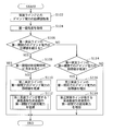
- FIG. 4 is a flowchart showing an example of the operation of the mounting line power control apparatus according to the present embodiment.
- FIG. 5 is a diagram for explaining processing performed by the mounting line power control apparatus according to the present embodiment.
- FIG. 6 is a diagram for explaining processing performed by the mounting line power control apparatus according to the present embodiment.
- FIG. 1 is an external view showing a configuration of a mounting line group including a mounting line power control apparatus according to an embodiment of the present invention.
- FIG. 2 is a block diagram showing a functional configuration of the mounting line power control apparatus according to the present embodiment.
- FIG. 3 is a diagram for explaining the demand power and its target value.
- FIG. 4 is a
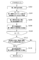
- FIG. 7 is a flowchart illustrating an example of a process in which the power usage change unit according to the present embodiment reduces the power usage in the first period of the mounting board production apparatus of the second mounting line.
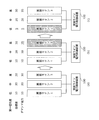
- FIG. 8 is a diagram illustrating a process in which the power usage change unit according to the present embodiment reduces the power usage in the first period of the mounting board production apparatus of the second mounting line.
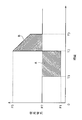
- FIG. 9 is a diagram illustrating a process in which the power usage changing unit according to the present embodiment reduces the power usage in the first period of the mounting board production apparatus of the second mounting line.
- FIG. 10 is a diagram illustrating a process in which the power usage changing unit according to the present embodiment reduces the power usage in the first period of the mounting board production apparatus of the second mounting line.
- FIG. 1 is an external view showing a configuration of a mounting line group 10 including a mounting line power control apparatus 100 according to an embodiment of the present invention.
- the mounting line group 10 includes a mounting line 11, a mounting line 12, and a mounting line power control apparatus 100.
- the mounting line group 10 is provided with two mounting lines, that is, the mounting line 11 and the mounting line 12, but may include three or more mounting lines.
- the mounting line 11 is a production line for transporting a board from an upstream mounting board production apparatus to a downstream mounting board production apparatus and producing a mounting board in which components such as electronic components are mounted on the board.
- the mounting line 11 includes two component mounting apparatuses 200, a printing apparatus 300, three inspection apparatuses 400, an adhesive application apparatus 500, and a reflow furnace 600 as mounting board production apparatuses.
- the component mounting apparatus 200 is an apparatus for mounting a component on a board. Specifically, the plurality of component mounting apparatuses 200 send boards from upstream to downstream, and mount components on the boards. That is, first, the upstream component mounting apparatus 200 receives a substrate and mounts the component on the substrate. Then, the board on which the component is mounted is sent to the component mounting apparatus 200 on the downstream side. In this way, the boards are sequentially sent to the component mounting apparatuses 200, and the components are mounted.
- the printing apparatus 300 is a screen printer that receives the substrate 20 from a stocker (not shown) for stocking the substrate and screen-prints a solder paste, which is a paste solder, on the surface of the substrate 20.
- the adhesive applying device 500 is a device that applies an adhesive on a substrate.
- the reflow furnace 600 is a device that fixes the component on the substrate after melting the solder or the like by heating the substrate 20 on which the component is mounted.
- the inspection device 400 is a device for inspecting the state on the substrate.
- the inspection apparatus 400 includes an inspection apparatus 400 that inspects the appearance of the soldering state by the printing apparatus 300, an inspection apparatus 400 that inspects the mounting state of components on the board by the component mounting apparatus 200, and a reflow furnace 600.
- the mounting board 20a on which components are mounted and inspected by the inspection apparatus 400 is sent to a stocker (not shown) for stocking the board.
- the mounting line 12 has the same configuration as the mounting line 11 and has the same function, a detailed description is omitted.
- the mounting line power control device 100 is a control device that controls the power used by the mounting line group 10. That is, the mounting line power control device 100 is a device that controls the power used by the mounting line 11 and the mounting line 12. Details of the mounting line power control apparatus 100 will be described later.
- FIG. 2 is a block diagram showing a functional configuration of the mounting line power control apparatus 100 according to the present embodiment.
- the mounting line power control apparatus 100 is a computer that controls the power used by the mounting line group 10.
- the mounting line power control apparatus 100 may be realized by a general-purpose computer system such as a personal computer executing a program, or may be realized by a dedicated computer system.
- the mounting line power control apparatus 100 includes a target value acquisition unit 110, a priority acquisition unit 120, a target value change unit 130, and a used power change unit 140.
- the target value acquisition unit 110 acquires a target value of demand power indicating the amount of power used for each predetermined period for each mounting line. That is, the target value acquisition unit 110 acquires target values of demand power for the mounting line 11 and the mounting line 12. If the mounting line group 10 includes three or more mounting lines, the target value acquisition unit 110 acquires a target value of demand power for the three or more mounting lines.
- the target value may be determined in advance by the user, or may be calculated by the target value acquisition unit 110. Further, the target value may be a different value for each predetermined period (for example, 1 shift, 1 day, 1 week, 1 month, etc.), or may be the same value.
- FIG. 3 is a diagram for explaining the demand power and its target value.
- the current power Pt when the elapsed time t is the demand time limit Td is the demand power.
- the demand time limit Td 30 (minutes). That is, the demand power is a value indicating the amount of power used every 30 minutes and is measured every 30 minutes.
- the reference power Py when the elapsed time t is the demand time limit Td is the target power Pa (kW).
- the target power Pa is set every 30 minutes when demand power is measured.
- a demand alarm is generated when the current power Pt at the elapsed time t becomes equal to or higher than the reference power Py at the elapsed time t. That is, a demand alarm is generated when the demand power is predicted to exceed the target power Pa.
- the lock time tr is an alarm suppression period. If the elapsed time t is within the lock time tr, the demand alarm is not generated or is recovered even if it is generated.
- the priority acquisition unit 120 acquires a first priority that is a priority for using power for each mounting line and a second priority that is a priority for using power for each mounting board production apparatus. To do. That is, among the mounting lines 11 and 12, the power can be preferentially used as the mounting line having a higher first priority. In addition, among the mounting board production apparatuses 200 to 600, the higher the second priority, the more the mounting board production apparatus can use power.
- first priority and the second priority may be determined in advance by the user, or may be calculated by the priority acquisition unit 120. Further, the first priority and the second priority may be different values for each predetermined period (for example, one shift, one day, one week, one month, etc.), or may be the same value. Good.
- the target value changing unit 130 is included in the mounting line group 10 when the demand power in the first period of the first mounting line that is the mounting line included in the mounting line group 10 exceeds the target value.
- the target value of demand power in the first period of the second mounting line having the first priority which is the priority for using the power for each mounting line is reduced.
- the first period is one of a plurality of periods during which demand power is measured, and a predetermined period (for example, one shift) in which the target value acquisition unit 110 acquires a target value of demand power. 1 day, 1 week, 1 month, etc.).
- the target value changing unit 130 reduces the target value of the demand power of the mounting line 12.
- the target value changing unit 130 determines whether or not the first period is included in the discounted time zone of the electricity rate unit price, and when determining that the first period is not included in the discounted time zone. If the target value of demand power in the first period of the second mounting line is reduced and it is determined that the first period is included in the discount period, the target of demand power in the first period of the second mounting line Does not reduce the value.
- the discount time zone is, for example, a midnight time zone. That is, the target value changing unit 130 has a function of automatically switching between two power modes, a daytime power mode and a midnight power mode.
- the target value changing unit 130 is configured to perform the first mounting line in the first period of the third mounting line, which is a different mounting line from the first mounting line, when the target value of demand power in the first period of the first mounting line is reduced.
- the target value of demand power can be increased.
- the used power changing unit 140 determines the used power in the first period of the mounting board production apparatus of the second mounting line so that the demand power in the first period of the second mounting line does not exceed the target value after the reduction. To reduce.
- the used power changing unit 140 includes a plurality of mounting board production apparatuses included in the second mounting line until the demand power in the first period of the second mounting line is equal to or lower than the target value after the reduction.
- the power reduction device which is the mounting board production device in which the power used in the first period is reduced is determined in descending order of the second priority, which is the priority for using the power for each mounting board production device.
- the power used in the first period of the reduction device is reduced. More specifically, the used power changing unit 140 reduces the used power in the first period by stopping the operation of the power reducing apparatus that is included in the power reducing device in the first period.
- the power consumption changing unit 140 further increases the power consumption of the power reduction device in the second period, and if the demand power of the second mounting line in the second period does not exceed the target value, Increase power usage in the second period.
- the second period is any period different from the first period among the plurality of periods in which the demand power is measured, and the target value acquisition unit 110 acquires a target value of the demand power.
- One of the periods (for example, 1 shift, 1 day, 1 week, 1 month, etc.) is different from the first period.
- FIG. 4 is a flowchart showing an example of the operation of the mounting line power control apparatus 100 according to the present embodiment.
- FIG 5 and 6 are diagrams for explaining processing performed by the mounting line power control apparatus 100 according to the present embodiment.
- the target value acquisition unit 110 acquires a target value of demand power for each mounting line (S102). For example, as shown in FIG. 5A, when the mounting line group 10 includes three mounting lines (the mounting line 1, the mounting line 2, and the mounting line 3 shown in FIG. 5), target value acquisition is performed.
- the unit 110 acquires a target value of demand power for the three mounting lines.
- the target value acquisition unit 110 acquires 10, 20, and 30 as target values of demand power of the mounting line 1, the mounting line 2, and the mounting line 3, respectively.
- the priority acquisition unit 120 acquires the first priority (S104). For example, as illustrated in FIG. 5A, the priority acquisition unit 120 sets “low”, “medium”, and “high” as the first priorities of the mounting line 1, the mounting line 2, and the mounting line 3. Is obtained.
- the target value changing unit 130 determines whether or not the demand power in the first period of the first mounting line that is the mounting line included in the mounting line group 10 exceeds the target value (S106). Specifically, as illustrated in FIG. 3, the target value changing unit 130 determines that the current power Pt at the elapsed time t within the first period of the first mounting line is equal to or greater than the reference power Py. It is determined that the demand power exceeds the target power Pa.
- the target value changing unit 130 sets the mounting line 3 as the first mounting line and performs the first mounting. Judge that the demand power of the line exceeds the target value.
- the target value changing unit 130 determines whether or not the first period is included in the discount time zone (S108). ).
- the target value changing unit 130 determines that the first period is not included in the discount time zone (NO in S108)
- the target value changing unit 130 reduces the target value of demand power in the first period of the second mounting line ( S110).
- the target value changing unit 130 reduces the target value of demand power of the mounting line 1 using the mounting line 1 as the second mounting line. Specifically, the target value changing unit 130 sets the demand power of the mounting line 1 so that the amount of decrease in the target value of the demand power of the mounting line 1 becomes the same value as the amount of increase in demand power of the mounting line 1. Reduce the target value.
- the power usage changing unit 140 is configured so that the demand power in the first period of the second mounting line does not exceed the target value after the reduction in the first period of the mounting board production apparatus that the second mounting line has.
- the power used is reduced (S112).
- the power usage changing unit 140 is configured so that the mounting line 1 that is the second mounting line is set so that the demand power of the mounting line 1 is equal to or lower than the target value after the reduction. Reduce the power consumption of the mounting board production equipment. A detailed description of the process in which the power usage changing unit 140 reduces the power usage in the first period of the mounting board production apparatus of the second mounting line will be described later.
- the target value changing unit 130 determines that the first period is included in the discount time zone (YES in S108)
- the target value changing unit 130 does not reduce the target value of demand power in the first period of the second mounting line. The process is terminated.
- the target value changing unit 130 determines that the demand power of the first mounting line is equal to or lower than the target value (NO in S106)
- the target value of the demand power in the first period of the first mounting line is reduced. It is determined whether it has been done (S114).
- the target value changing unit 130 determines that the demand value target value of the first mounting line has been reduced with the mounting line 1 as the first mounting line.
- the target value changing unit 130 determines that the target value of demand power in the first period of the first mounting line has been reduced (YES in S114)
- the target value changing unit 130 is a third mounting line that is different from the first mounting line.
- the target value of demand power in the first period of the mounting line is increased (S116).
- the target value changing unit 130 uses the mounting line 2 and the mounting line 3 as the third mounting line, and the target value of the demand power of the mounting line 2 and the mounting line 3. Increase.
- the target value changing unit 130 is configured so that the increase amount of the target power demand value of the mounting line 2 and the mounting line 3 becomes the same value as the decrease amount of the demand power of the mounting line 1. Increase the target value of demand power on line 3.
- the used power changing unit 140 increases the used power in the first period of the mounting board production apparatus included in the third mounting line as necessary (S118). As a result, as shown in FIG. 6C, the power usage changing unit 140 increases the demand power of the mounting line 2 and the mounting line 3 so as not to exceed the increased target value.
- the target value changing unit 130 determines that the target value of demand power in the first period of the first mounting line has not been reduced (NO in S114), the demand value in the first period of the third mounting line. The process is terminated without increasing the power target value.
- FIG. 7 is a flowchart illustrating an example of a process in which the power usage changing unit 140 according to the present embodiment reduces the power usage in the first period of the mounting board production apparatus of the second mounting line.
- 8 to 10 are diagrams for explaining processing in which the used power changing unit 140 according to the present embodiment reduces the used power in the first period of the mounting board production apparatus of the second mounting line.
- the priority acquisition unit 120 acquires a second priority for each mounting board production device included in the second mounting line (S202). For example, as shown in FIG. 8A, the priority acquisition unit 120 acquires the second priority of each of the mounting board production apparatuses 200 to 600.
- the used power changing unit 140 repeatedly performs the following processing until the demand power in the first period of the second mounting line becomes equal to or less than the target value after reduction (loop 1: S204 to S210).
- the used power changing unit 140 is a mounted board production device that reduces the used power in the first period in descending order of the second priority among the plurality of mounted board production devices included in the second mounting line.
- a power reduction device is determined (S206). For example, as shown in FIG. 8 (a), the power consumption changing unit 140 uses a mounting board production apparatus having a second priority of “low” (in the figure, one component mounting apparatus 200 and three inspections). The device 400) is determined to be a power reduction device.
- the used power changing unit 140 reduces the used power in the first period of the power reducing device (S208). Specifically, the used power changing unit 140 reduces the used power in the first period by stopping the operation of the power reducing device that is a device included in the power reducing device in the first period.
- the power usage changing unit 140 includes a power reduction device that is a device included in the power reduction device (a mounting board production device indicated by hatching in FIG. 8). Stop operation in the first period.
- the power reduction device is, for example, a mounting head or a feeder that supplies components to the mounting head if the mounting board production apparatus is the component mounting apparatus 200. That is, the power usage change unit 140 reduces standby power of the motor by stopping power supply to, for example, a linear motor that drives the feeder.
- the power usage changing unit 140 further determines the power reduction devices in order of increasing second priority (S206). The power used in the determined first period of the power reduction device is reduced (S208).
- the power usage changing unit 140 includes a mounting board production apparatus (in the figure, one component mounting apparatus 200 and an adhesive application apparatus) with the second priority “medium”. 500 and the reflow furnace 600) are determined as the power reduction device, and the operation of the power reduction device in the first period is stopped.
- the power usage changing unit 140 is provided when the substrate 20 is continuously inserted ((a) in FIG. 8), when the substrate 20 exists every other facility ((b) in FIG. 8), and mounted. As in the case where there is one substrate 20 on the line ((c) in FIG. 8), the power consumption is reduced by limiting the number of substrates 20 on the mounting line.
- the power usage change part 140 is the 2nd period even if it increases the power usage of a power reduction apparatus to a 2nd period. It is determined whether the demand power of the second mounting line does not exceed the target value (S212).
- the power consumption changing unit 140 determines that the demand power of the second mounting line in the second period does not exceed the target value even if the power consumption of the power reduction device is increased in the second period (YES in S212), The power consumption of the power reduction device is increased in the second period (S214).
- the process in which the power usage changing unit 140 increases the power usage of the power reduction device in the second period will be specifically described with reference to FIGS. 9 and 10.
- the power reduction device is the reflow furnace 600.
- FIG. 9 is a graph showing electric power used when the reflow furnace 600 starts and stops.
- the reflow furnace 600 is normally operated by using the electric power P2 used from time 0 to time T1.
- the power used is reduced to the power used P1.
- the power used increases up to the power P3. Thereafter, the reflow furnace 600 stably operates from the time T3 and performs normal operation with the electric power P2 used.
- the power consumption A that is reduced between time T1 and time T2 is greater than the power consumption B that is increased between time T2 and time T3.
- the power consumption is reduced as a whole. That is, in this case, the reflow furnace 600 starts and stops, so that the amount of power used is reduced.
- the demand power exceeds the target value, thereby reducing the target value of the demand power of other mounting lines. There may be a need.
- FIG. 10 is a graph showing electric power used when the reflow furnace 600 of a plurality of mounting lines starts and stops.
- the reflow furnaces R1 to R3 are scheduled to be activated between time T2 and time T3.
- the reflow furnaces R1 to R3 are mounting board production apparatuses provided in different mounting lines.
- the reflow furnace R1 is preferentially activated between time T2 and time T3.
- the used power changing unit 140 determines that the reflow furnace R1 has stopped the start time of the reflow furnaces R2 and R3 from the time between time T2 and time T3. The time is changed to a time between time T1 and time T2. Thereby, the used power changing unit 140 can reduce the used power of the reflow furnaces R2 and R3 between time T2 and time T3.
- the power consumption of the reflow furnaces R2 and R3 between time T1 and time T2 increases, but since the power consumption is reduced between time T1 and time T2, the power consumption is reduced.
- the power can be leveled and the reflow furnaces R2 and R3 can be started.
- the mounting line power control apparatus 100 when the demand power of the first mounting line exceeds the target value in the first period, the target value of the demand power of the second mounting line is set.
- the power consumption of the mounting board production apparatus included in the second mounting line is reduced so as not to exceed the target value after the reduction.
- the power reduction devices are determined in order of the second priority, and the operation of the equipment included in the determined power reduction device is performed.
- the power consumption is reduced by stopping the operation. As a result, the power used can be reduced in order from the mounting board production apparatus with the lowest priority.
- the power consumption of the power reduction device is increased in the second period. Therefore, the operation of the power reduction device that was scheduled to be performed in the first period can be performed in the second period without exceeding the target value.
- the demand value target power of the second mounting line is reduced. If the first period is included in the discount time zone, the demand power of the second mounting line is reduced. Do not reduce the target value. That is, in the time zone other than the discount time zone, a large amount of power is used in the factory, so the target value of demand power for the second mounting line is reduced. Moreover, in the discount time zone in which the power used in the factory is reduced, the target value of demand power for the second mounting line is not reduced. Thereby, the use mode of electric power can be switched for every time slot
- the target value of demand power of the first mounting line when the target value of demand power of the first mounting line is reduced, the target value of demand power of the mounting line different from the first mounting line is increased.
- the mounting line power control apparatus 100 according to the present invention has been described using the above embodiment, but the present invention is not limited to this.
- the priority acquisition unit 120 acquires the first priority and the second priority, and the power usage change unit 140 determines the power reduction device from the first priority and the second priority. It was decided to reduce the power used by the power reduction device. However, the priority acquisition unit 120 does not have to acquire the second priority, and the power usage changing unit 140 determines the power reduction device only from the first priority and reduces the power usage of the power reduction device. May be.
- the target value changing unit 130 determines whether or not the first period is included in the discount time zone, and based on the determination result, the demand value in the first period of the second mounting line. The target value of power was reduced. However, the target value changing unit 130 may reduce the target value of demand power in the first period of the second mounting line regardless of whether or not the first period is included in the discount time zone.
- the target value changing unit 130 determines the demand power in the first period of the third mounting line when the target value of the demand power in the first period of the first mounting line is reduced. The target value was increased. However, the target value changing unit 130 does not increase the target value of demand power in the first period of the third mounting line even if the target value of demand power in the first period of the first mounting line is reduced. May be.
- the target value changing unit 130 determines whether or not the demand power exceeds the target value for each mounting line.
- the target value changing unit 130 may repeat the feedback of the measurement error of the power consumption of each device to correct the demand power so that the determination is accurately performed.
- the target value changing unit 130 sets the second amount of demand power for the second mounting line so that the amount of decrease decreases to the same value as the amount of increase in demand power for the first mounting line. We decided to reduce the target value of demand power on the mounting line.
- the amount of decrease in the target value of demand power in the second mounting line is not limited, and may be larger or smaller than the amount of increase in demand power in the first mounting line.
- the target value changing unit 130 causes the third mounting line so that the increase amount of the demand power target value becomes the same value as the decrease amount of the demand power of the first mounting line.
- the target value of demand power on the mounting line was increased.
- the increase amount of the target value of the demand power of the third mounting line is not limited, and may be larger or smaller than the decrease amount of the demand power of the first mounting line.
- the used power changing unit 140 changes the starting time of the reflow furnace 600 to reduce the used power so that the demand power does not exceed the target value.
- the used power changing unit 140 may change the starting time of the motor to reduce the used power so that the demand power does not exceed the target value. In this case, by shifting the start and stop of the motor between the mounting lines, the start power of the motor and the regenerative power by the motor can be offset, and the power used can be reduced.
- the present invention can be realized not only as such a mounting line power control apparatus 100 but also as a mounting line power control method having a characteristic process performed by a processing unit included in the mounting line power control apparatus 100 as a step. Can also be realized. Further, it can be realized as a program or an integrated circuit for causing a computer to execute characteristic processing included in the mounting line power control method. Needless to say, such a program can be distributed via a recording medium such as a CD-ROM and a transmission medium such as the Internet.
- the present invention may be adapted to increase / decrease in the target value of demand power of the entire mounting line when there is a change in the power consumption of other large load fluctuation facilities in the factory other than the mounting line.
- the present invention can be applied to a mounting line power control apparatus that controls power consumption of a plurality of mounting lines, and in particular, a mounting line power control apparatus that can efficiently suppress an increase in power usage in the plurality of mounting lines as a whole. Applicable to etc.
Landscapes
- Engineering & Computer Science (AREA)
- Manufacturing & Machinery (AREA)
- Microelectronics & Electronic Packaging (AREA)
- Operations Research (AREA)
- General Factory Administration (AREA)
- Supply And Distribution Of Alternating Current (AREA)
- Supply And Installment Of Electrical Components (AREA)
Abstract
Description
現在電力Pt=(経過時間tでの電力量-経過時間0での電力量)×2 (式1)で算出される。
基準電力Py=目標電力Pa×経過時間t÷30 (式2)
で算出される。
11、12 実装ライン
20 基板
20a 実装基板
100 実装ライン電力制御装置
110 目標値取得部
120 優先度取得部
130 目標値変更部
140 使用電力変更部
200 部品実装装置(実装基板生産装置)
300 印刷装置(実装基板生産装置)
400 検査装置(実装基板生産装置)
500 接着剤塗布装置(実装基板生産装置)
600 リフロー炉(実装基板生産装置)
Claims (9)
- 部品が実装された実装基板を生産するための実装基板生産装置を有する実装ラインを複数備える実装ライン群の使用電力を制御する実装ライン電力制御装置であって、
前記実装ラインごとに、第一期間での使用電力量を示すデマンド電力の目標値を取得する目標値取得部と、
前記実装ラインごとの電力を使用する優先度である第一優先度を取得する優先度取得部と、
前記実装ライン群に含まれる第一実装ラインの前記第一期間でのデマンド電力が目標値を超える場合に、前記実装ライン群に含まれ前記第一実装ラインよりも前記第一優先度が低い第二実装ラインの前記第一期間でのデマンド電力の目標値を低減する目標値変更部と、
前記第二実装ラインの前記第一期間でのデマンド電力が低減後の目標値を超えないように、前記第二実装ラインが有する実装基板生産装置の前記第一期間での使用電力を低減する使用電力変更部と
を備える実装ライン電力制御装置。 - 前記第二実装ラインは、複数の前記実装基板生産装置を有しており、
前記優先度取得部は、前記実装基板生産装置ごとの電力を使用する優先度である第二優先度を取得し、
前記使用電力変更部は、前記第二実装ラインの前記第一期間でのデマンド電力が低減後の目標値以下になるまで、前記第二実装ラインに含まれる複数の実装基板生産装置のうち、前記第二優先度が低い順に、前記第一期間での使用電力が低減される実装基板生産装置である電力低減装置を決定し、決定した前記電力低減装置の前記第一期間での使用電力を低減する
請求項1に記載の実装ライン電力制御装置。 - 前記電力低減装置は、複数の機器を備えており、
前記使用電力変更部は、前記電力低減装置に含まれる機器である電力低減機器の前記第一期間での稼働を停止させることで、前記第一期間での使用電力を低減する
請求項2に記載の実装ライン電力制御装置。 - 前記目標値取得部は、さらに、前記第一期間とは異なる第二期間での前記第二実装ラインのデマンド電力の目標値を取得し、
前記使用電力変更部は、さらに、前記電力低減装置の使用電力を前記第二期間に増加させても前記第二期間での前記第二実装ラインのデマンド電力が目標値を超えない場合、前記電力低減装置の使用電力を前記第二期間に増加させる
請求項2又は3に記載の実装ライン電力制御装置。 - 前記電力低減装置は、部品が実装された基板を熱することにより部品を当該基板上に固定させる第一リフロー炉であり、
前記使用電力変更部は、前記第一リフロー炉の起動時刻を、前記第一期間内の時刻から、前記第一リフロー炉を有する実装ラインとは異なる実装ラインが有する第二リフロー炉が停止している期間に含まれる前記第二期間内の時刻に変更することで、前記第一期間での前記第一リフロー炉の使用電力を低減し、前記第二期間での前記第一リフロー炉の使用可能な使用電力を増加させる
請求項4に記載の実装ライン電力制御装置。 - 前記目標値変更部は、
前記第一期間が、電気料金単価が割安の割安時間帯に含まれるか否かを判断し、
前記第一期間が前記割安時間帯に含まれないと判断した場合は、前記第二実装ラインの前記第一期間でのデマンド電力の目標値を低減し、
前記第一期間が前記割安時間帯に含まれると判断した場合は、前記第二実装ラインの前記第一期間でのデマンド電力の目標値を低減しない
請求項1~5のいずれか1項に記載の実装ライン電力制御装置。 - 前記目標値変更部は、さらに、前記第一実装ラインの前記第一期間でのデマンド電力の目標値が低減された場合に、前記第一実装ラインと異なる第三実装ラインの前記第一期間でのデマンド電力の目標値を増加させる
請求項1~6のいずれか1項に記載の実装ライン電力制御装置。 - 部品が実装された実装基板を生産するための実装基板生産装置を有する実装ラインを複数備える実装ライン群の使用電力を制御する実装ライン電力制御方法であって、
前記実装ラインごとに、第一期間での使用電力量を示すデマンド電力の目標値を取得する目標値取得ステップと、
前記実装ラインごとの電力を使用する優先度である第一優先度を取得する優先度取得ステップと、
前記実装ライン群に含まれる第一実装ラインの前記第一期間でのデマンド電力が目標値を超える場合に、前記実装ライン群に含まれ前記第一実装ラインよりも前記第一優先度が低い第二実装ラインの前記第一期間でのデマンド電力の目標値を低減する目標値変更ステップと、
前記第二実装ラインの前記第一期間でのデマンド電力が低減後の目標値を超えないように、前記第二実装ラインが有する実装基板生産装置の前記第一期間での使用電力を低減する使用電力変更ステップと
を含む実装ライン電力制御方法。 - 部品が実装された実装基板を生産するための実装基板生産装置を有する実装ラインを複数備える実装ライン群の使用電力を制御するためのプログラムであって、
前記実装ラインごとに、第一期間での使用電力量を示すデマンド電力の目標値を取得する目標値取得ステップと、
前記実装ラインごとの電力を使用する優先度である第一優先度を取得する優先度取得ステップと、
前記実装ライン群に含まれる第一実装ラインの前記第一期間でのデマンド電力が目標値を超える場合に、前記実装ライン群に含まれ前記第一実装ラインよりも前記第一優先度が低い第二実装ラインの前記第一期間でのデマンド電力の目標値を低減する目標値変更ステップと、
前記第二実装ラインの前記第一期間でのデマンド電力が低減後の目標値を超えないように、前記第二実装ラインが有する実装基板生産装置の前記第一期間での使用電力を低減する使用電力変更ステップと
をコンピュータに実行させるプログラム。
Priority Applications (5)
| Application Number | Priority Date | Filing Date | Title |
|---|---|---|---|
| JP2011527099A JP4813632B1 (ja) | 2010-03-31 | 2011-03-22 | 実装ライン電力制御装置及び実装ライン電力制御方法 |
| DE112011101119T DE112011101119T5 (de) | 2010-03-31 | 2011-03-22 | Bestückungslinien-Leistungssteuervorrlchtung und Bestückungslinien-Leistungssteuervertahren |
| KR1020117031034A KR20120132615A (ko) | 2010-03-31 | 2011-03-22 | 실장 라인 전력 제어 장치 및 실장 라인 전력 제어 방법 |
| CN201180002801.6A CN102475003B (zh) | 2010-03-31 | 2011-03-22 | 安装流水线功率控制装置以及安装流水线功率控制方法 |
| US13/382,164 US8918194B2 (en) | 2010-03-31 | 2011-03-22 | Mounting-line power control device and mounting-line power control method |
Applications Claiming Priority (2)
| Application Number | Priority Date | Filing Date | Title |
|---|---|---|---|
| JP2010084203 | 2010-03-31 | ||
| JP2010-084203 | 2010-03-31 |
Publications (1)
| Publication Number | Publication Date |
|---|---|
| WO2011121934A1 true WO2011121934A1 (ja) | 2011-10-06 |
Family
ID=44711702
Family Applications (1)
| Application Number | Title | Priority Date | Filing Date |
|---|---|---|---|
| PCT/JP2011/001669 Ceased WO2011121934A1 (ja) | 2010-03-31 | 2011-03-22 | 実装ライン電力制御装置及び実装ライン電力制御方法 |
Country Status (6)
| Country | Link |
|---|---|
| US (1) | US8918194B2 (ja) |
| JP (1) | JP4813632B1 (ja) |
| KR (1) | KR20120132615A (ja) |
| CN (1) | CN102475003B (ja) |
| DE (1) | DE112011101119T5 (ja) |
| WO (1) | WO2011121934A1 (ja) |
Cited By (3)
| Publication number | Priority date | Publication date | Assignee | Title |
|---|---|---|---|---|
| JP2015103120A (ja) * | 2013-11-27 | 2015-06-04 | 三菱重工業株式会社 | 消費電力制御システム及び方法 |
| WO2017090192A1 (ja) * | 2015-11-27 | 2017-06-01 | 富士機械製造株式会社 | 部品供給装置の電源制御装置および電源制御方法 |
| JPWO2017094070A1 (ja) * | 2015-11-30 | 2018-09-13 | 株式会社Fuji | 部品供給装置の電源制御装置および電源制御方法 |
Families Citing this family (2)
| Publication number | Priority date | Publication date | Assignee | Title |
|---|---|---|---|---|
| KR102524778B1 (ko) * | 2016-01-26 | 2023-04-21 | 한화정밀기계 주식회사 | 부품실장 장비의 통합 제어 시스템 |
| KR102711984B1 (ko) * | 2016-09-20 | 2024-09-27 | 한화정밀기계 주식회사 | 인라인 유휴 시간 예측 장치 |
Citations (3)
| Publication number | Priority date | Publication date | Assignee | Title |
|---|---|---|---|---|
| JPH04138026A (ja) * | 1990-09-28 | 1992-05-12 | Amada Metrecs Co Ltd | 金属加工ラインの需要電力制御装置 |
| JPH11232332A (ja) * | 1998-02-10 | 1999-08-27 | Tokyo Electric Power Co Inc:The | 生産ラインにおける日程計画立案方法 |
| JP2006313806A (ja) * | 2005-05-09 | 2006-11-16 | Matsushita Electric Ind Co Ltd | 電子部品実装用装置および電子部品実装用装置における動力供給制御方法 |
Family Cites Families (14)
| Publication number | Priority date | Publication date | Assignee | Title |
|---|---|---|---|---|
| JP2001197661A (ja) | 1999-11-01 | 2001-07-19 | Kazuo Miwa | 節電制御装置及び省エネルギーシステム |
| US8463616B2 (en) * | 2002-10-15 | 2013-06-11 | Invensys Systems, Inc. | Scheduling a process according to time-varying input prices |
| EP1566875A1 (en) * | 2004-02-19 | 2005-08-24 | Alcatel | Energy management method |
| JP4963064B2 (ja) * | 2004-03-04 | 2012-06-27 | シャープ株式会社 | 半導体装置の製造方法および半導体検査装置 |
| JP4475586B2 (ja) | 2005-03-28 | 2010-06-09 | パナソニック株式会社 | 電力監視方法 |
| EP1849342B1 (en) | 2005-02-17 | 2009-08-19 | Panasonic Corporation | Mounting condition determining method, mounting condition determining device, and mounting apparatus |
| JP4373403B2 (ja) | 2005-02-18 | 2009-11-25 | パナソニック株式会社 | 実装条件決定方法 |
| US7606151B2 (en) | 2005-04-21 | 2009-10-20 | Intel Corporation | Power reduction in switch architectures |
| CN1728411A (zh) * | 2005-06-24 | 2006-02-01 | 南京汉德森半导体照明有限公司 | 高散热效率的大功率半导体发光二极管封装基座及生产工艺 |
| US7725745B2 (en) | 2006-12-19 | 2010-05-25 | Intel Corporation | Power aware software pipelining for hardware accelerators |
| KR20090125151A (ko) * | 2007-04-03 | 2009-12-03 | 파나소닉 주식회사 | 부품 실장 방법 |
| US7962770B2 (en) * | 2007-12-19 | 2011-06-14 | International Business Machines Corporation | Dynamic processor reconfiguration for low power without reducing performance based on workload execution characteristics |
| CN101493761B (zh) * | 2008-01-25 | 2013-05-29 | 国际商业机器公司 | 处理器流水线处理指令的方法及相应的处理器 |
| JP2010062398A (ja) * | 2008-09-05 | 2010-03-18 | Fujitsu Ten Ltd | 回路部品製造方法、回路部品、及び回路部品製造装置 |
-
2011
- 2011-03-22 CN CN201180002801.6A patent/CN102475003B/zh not_active Expired - Fee Related
- 2011-03-22 WO PCT/JP2011/001669 patent/WO2011121934A1/ja not_active Ceased
- 2011-03-22 KR KR1020117031034A patent/KR20120132615A/ko not_active Withdrawn
- 2011-03-22 US US13/382,164 patent/US8918194B2/en active Active
- 2011-03-22 JP JP2011527099A patent/JP4813632B1/ja not_active Expired - Fee Related
- 2011-03-22 DE DE112011101119T patent/DE112011101119T5/de not_active Withdrawn
Patent Citations (3)
| Publication number | Priority date | Publication date | Assignee | Title |
|---|---|---|---|---|
| JPH04138026A (ja) * | 1990-09-28 | 1992-05-12 | Amada Metrecs Co Ltd | 金属加工ラインの需要電力制御装置 |
| JPH11232332A (ja) * | 1998-02-10 | 1999-08-27 | Tokyo Electric Power Co Inc:The | 生産ラインにおける日程計画立案方法 |
| JP2006313806A (ja) * | 2005-05-09 | 2006-11-16 | Matsushita Electric Ind Co Ltd | 電子部品実装用装置および電子部品実装用装置における動力供給制御方法 |
Cited By (7)
| Publication number | Priority date | Publication date | Assignee | Title |
|---|---|---|---|---|
| JP2015103120A (ja) * | 2013-11-27 | 2015-06-04 | 三菱重工業株式会社 | 消費電力制御システム及び方法 |
| WO2015079819A1 (ja) | 2013-11-27 | 2015-06-04 | 三菱重工業株式会社 | 消費電力制御システム及び方法 |
| US10175746B2 (en) | 2013-11-27 | 2019-01-08 | Mitsubishi Heavy Industries, Ltd. | Power consumption control system and method |
| WO2017090192A1 (ja) * | 2015-11-27 | 2017-06-01 | 富士機械製造株式会社 | 部品供給装置の電源制御装置および電源制御方法 |
| US10874041B2 (en) | 2015-11-27 | 2020-12-22 | Fuji Corporation | Feeder device and component mounting machine |
| JPWO2017094070A1 (ja) * | 2015-11-30 | 2018-09-13 | 株式会社Fuji | 部品供給装置の電源制御装置および電源制御方法 |
| US11051439B2 (en) | 2015-11-30 | 2021-06-29 | Fuji Corporation | Power supply control device and power supply control method for component supply device |
Also Published As
| Publication number | Publication date |
|---|---|
| CN102475003B (zh) | 2014-12-17 |
| CN102475003A (zh) | 2012-05-23 |
| JPWO2011121934A1 (ja) | 2013-07-04 |
| KR20120132615A (ko) | 2012-12-06 |
| US20120102343A1 (en) | 2012-04-26 |
| DE112011101119T5 (de) | 2013-01-10 |
| JP4813632B1 (ja) | 2011-11-09 |
| US8918194B2 (en) | 2014-12-23 |
Similar Documents
| Publication | Publication Date | Title |
|---|---|---|
| JP4813632B1 (ja) | 実装ライン電力制御装置及び実装ライン電力制御方法 | |
| JP2012194607A (ja) | 制御装置、制御方法、プログラム、記録媒体 | |
| JP5516599B2 (ja) | 電源装置 | |
| US20140330549A1 (en) | Simulation device, simulation method, and recording medium | |
| WO2015019412A1 (ja) | 準備作業支援システム | |
| KR101683354B1 (ko) | 전력 공급 장치 및 전력 공급 전환 방법 | |
| JP6248046B2 (ja) | 生産データ作成システムおよび生産データ作成方法 | |
| US20140129045A1 (en) | Control device, heating device control system, control method, program, and recording medium | |
| CN111758309B (zh) | 信息处理装置及信息处理方法 | |
| JP6037464B2 (ja) | 電気機器の寿命を予測する装置及び方法 | |
| KR101036542B1 (ko) | 반도체 제조 장치용 히터 시스템 | |
| WO2012124411A1 (ja) | 制御装置、制御方法、プログラム、記録媒体 | |
| CN101802742A (zh) | 电源装置及电子设备 | |
| JP2011187088A (ja) | 制御装置、制御方法、プログラム、記録媒体 | |
| JP5822297B2 (ja) | 電源システム、サーバシステム、及び電源システムの電力制御方法 | |
| JP2000050500A (ja) | デマンド制御方法 | |
| JP4586770B2 (ja) | 待機式無停電電源システム | |
| US20100176780A1 (en) | Power supply device and electronic apparatus | |
| JP2006318354A (ja) | 電子機器及び電源制御装置 | |
| JP2006101592A (ja) | 制御装置および給電制御方法 | |
| JP2006340438A (ja) | 電源装置、情報処理装置、および電源制御方法 | |
| JP2024130560A (ja) | 設備管理方法、設備管理装置、及び設備管理プログラム | |
| JP2025135348A (ja) | 生産システム | |
| JP2026061199A (ja) | 管理装置、管理システム、管理方法、及び、管理装置のためのコンピュータプログラム | |
| Mach et al. | Failure mode and effects analysis of a process of reflow lead-free soldering |
Legal Events
| Date | Code | Title | Description |
|---|---|---|---|
| WWE | Wipo information: entry into national phase |
Ref document number: 201180002801.6 Country of ref document: CN |
|
| WWE | Wipo information: entry into national phase |
Ref document number: 2011527099 Country of ref document: JP |
|
| 121 | Ep: the epo has been informed by wipo that ep was designated in this application |
Ref document number: 11762186 Country of ref document: EP Kind code of ref document: A1 |
|
| ENP | Entry into the national phase |
Ref document number: 20117031034 Country of ref document: KR Kind code of ref document: A |
|
| WWE | Wipo information: entry into national phase |
Ref document number: 13382164 Country of ref document: US |
|
| WWE | Wipo information: entry into national phase |
Ref document number: 112011101119 Country of ref document: DE Ref document number: 1120111011199 Country of ref document: DE |
|
| 122 | Ep: pct application non-entry in european phase |
Ref document number: 11762186 Country of ref document: EP Kind code of ref document: A1 |