WO2011121815A1 - Système de gestion d'énergie, appareil de gestion d'énergie et procédé de gestion d'énergie - Google Patents
Système de gestion d'énergie, appareil de gestion d'énergie et procédé de gestion d'énergie Download PDFInfo
- Publication number
- WO2011121815A1 WO2011121815A1 PCT/JP2010/065176 JP2010065176W WO2011121815A1 WO 2011121815 A1 WO2011121815 A1 WO 2011121815A1 JP 2010065176 W JP2010065176 W JP 2010065176W WO 2011121815 A1 WO2011121815 A1 WO 2011121815A1
- Authority
- WO
- WIPO (PCT)
- Prior art keywords
- heat storage
- water heater
- amount
- electric water
- energy management
- Prior art date
Links
Images


Classifications
-
- H—ELECTRICITY
- H02—GENERATION; CONVERSION OR DISTRIBUTION OF ELECTRIC POWER
- H02J—CIRCUIT ARRANGEMENTS OR SYSTEMS FOR SUPPLYING OR DISTRIBUTING ELECTRIC POWER; SYSTEMS FOR STORING ELECTRIC ENERGY
- H02J3/00—Circuit arrangements for ac mains or ac distribution networks
- H02J3/28—Arrangements for balancing of the load in a network by storage of energy
- H02J3/32—Arrangements for balancing of the load in a network by storage of energy using batteries with converting means
-
- H—ELECTRICITY
- H02—GENERATION; CONVERSION OR DISTRIBUTION OF ELECTRIC POWER
- H02J—CIRCUIT ARRANGEMENTS OR SYSTEMS FOR SUPPLYING OR DISTRIBUTING ELECTRIC POWER; SYSTEMS FOR STORING ELECTRIC ENERGY
- H02J15/00—Systems for storing electric energy
-
- H—ELECTRICITY
- H02—GENERATION; CONVERSION OR DISTRIBUTION OF ELECTRIC POWER
- H02J—CIRCUIT ARRANGEMENTS OR SYSTEMS FOR SUPPLYING OR DISTRIBUTING ELECTRIC POWER; SYSTEMS FOR STORING ELECTRIC ENERGY
- H02J7/00—Circuit arrangements for charging or depolarising batteries or for supplying loads from batteries
- H02J7/34—Parallel operation in networks using both storage and other dc sources, e.g. providing buffering
- H02J7/35—Parallel operation in networks using both storage and other dc sources, e.g. providing buffering with light sensitive cells
-
- Y—GENERAL TAGGING OF NEW TECHNOLOGICAL DEVELOPMENTS; GENERAL TAGGING OF CROSS-SECTIONAL TECHNOLOGIES SPANNING OVER SEVERAL SECTIONS OF THE IPC; TECHNICAL SUBJECTS COVERED BY FORMER USPC CROSS-REFERENCE ART COLLECTIONS [XRACs] AND DIGESTS
- Y02—TECHNOLOGIES OR APPLICATIONS FOR MITIGATION OR ADAPTATION AGAINST CLIMATE CHANGE
- Y02E—REDUCTION OF GREENHOUSE GAS [GHG] EMISSIONS, RELATED TO ENERGY GENERATION, TRANSMISSION OR DISTRIBUTION
- Y02E10/00—Energy generation through renewable energy sources
- Y02E10/50—Photovoltaic [PV] energy
- Y02E10/56—Power conversion systems, e.g. maximum power point trackers
-
- Y—GENERAL TAGGING OF NEW TECHNOLOGICAL DEVELOPMENTS; GENERAL TAGGING OF CROSS-SECTIONAL TECHNOLOGIES SPANNING OVER SEVERAL SECTIONS OF THE IPC; TECHNICAL SUBJECTS COVERED BY FORMER USPC CROSS-REFERENCE ART COLLECTIONS [XRACs] AND DIGESTS
- Y02—TECHNOLOGIES OR APPLICATIONS FOR MITIGATION OR ADAPTATION AGAINST CLIMATE CHANGE
- Y02E—REDUCTION OF GREENHOUSE GAS [GHG] EMISSIONS, RELATED TO ENERGY GENERATION, TRANSMISSION OR DISTRIBUTION
- Y02E70/00—Other energy conversion or management systems reducing GHG emissions
- Y02E70/30—Systems combining energy storage with energy generation of non-fossil origin
-
- Y—GENERAL TAGGING OF NEW TECHNOLOGICAL DEVELOPMENTS; GENERAL TAGGING OF CROSS-SECTIONAL TECHNOLOGIES SPANNING OVER SEVERAL SECTIONS OF THE IPC; TECHNICAL SUBJECTS COVERED BY FORMER USPC CROSS-REFERENCE ART COLLECTIONS [XRACs] AND DIGESTS
- Y02—TECHNOLOGIES OR APPLICATIONS FOR MITIGATION OR ADAPTATION AGAINST CLIMATE CHANGE
- Y02P—CLIMATE CHANGE MITIGATION TECHNOLOGIES IN THE PRODUCTION OR PROCESSING OF GOODS
- Y02P90/00—Enabling technologies with a potential contribution to greenhouse gas [GHG] emissions mitigation
- Y02P90/50—Energy storage in industry with an added climate change mitigation effect
Definitions
- the present invention is an energy management system applied when operating energy equipment such as a solar power generation facility, a storage battery, and an electric water heater at the consumer's end, and a customer applied to the system or in the vicinity of the customer. It relates to installed energy management equipment.
- the features of this method are as follows.
- the demand for hot water in the consumer is sufficient even after the time period when the solar power generation facility is generating electricity in the daytime.
- the heat storage operation time is shifted from the night before to the time when the solar power generation facility generates power during the daytime, there is no shortage of hot water and the convenience of consumers is not impaired. It is characterized by the fact that no special initial costs are incurred because the installed electric water heater is used for hot water use.
- the voltage distribution of the distribution system is affected not only by the situation of the customer but also by the load situation of the entire distribution system, etc. Depending on the situation, there is a possibility that the voltage increase suppressing function of the photovoltaic power generation facility operates and the power generation amount is suppressed.
- the amount of power generated by the solar power generation facility is large and exceeds the capacity of the electric water heater or storage battery at the consumer end, it is possible that the amount of power generated by the solar power generation facility must be suppressed. There is sex.
- the challenge is how to secure the amount of load that can absorb solar power.
- the present invention has been made to solve the above-described problems, and in order to improve the total energy efficiency in the absorption of the amount of photovoltaic power generation by the energy storage facility, to avoid the voltage rise suppression function of the photovoltaic power generation facility.
- An object of the present invention is to provide a means that enables the optimum operation of an energy storage facility for maximizing the amount that can be absorbed.
- the system operation calculation unit for predicting the voltage distribution of the distribution system for the next day or the balance of supply and demand for the entire system using the state monitoring data of the power system, and a predetermined time such as the next day from the system operation calculation unit.
- a customer cooperation calculation unit that obtains prediction information of the voltage distribution or supply / demand balance amount of the distribution system of the power supply, and calculates a demand increase target value necessary for avoiding the suppression of the amount of photovoltaic power generation at the customer end using them
- the control unit acquires the demand amount increase target value from the consumer cooperation calculation unit, and controls the energy storage facility so as to satisfy the demand amount increase target value at the consumer end.
- the control for absorbing the amount of photovoltaic power generation in the energy storage facility of other nearby customers when there is a shortage of photovoltaic power generation for energy storage in an energy storage facility within a single customer, the energy including the photovoltaic power generation of other nearby customers It controls energy storage in the storage facility.
- the influence on the power system is reduced, and the power generation amount of the solar power generation is increased, so that low-carbon and efficient power generation is achieved. And consumption can be performed.
- FIG. 1 is a diagram showing an example of the entire system configuration according to the present embodiment.
- Embodiment it is comprised with the electric power grid
- the power system 10 supplies the power obtained by the power generation facility 11 to the transformer 13 via the transmission line 12, and the power transformed by the transformer 13 is supplied to the large-scale customer 20 via the distribution line 14. To the building 21, factory 22, supermarket 23, etc. In addition, power is supplied to a school 31 and a community center 32, which are relatively large consumers 30 in a residential area. Furthermore, the electric power transformed by the transformer 40 is supplied to the customer 100 as a general household through the distribution line 41.
- a photovoltaic power generation facility (PV) 111 that is a facility that receives sunlight and converts it into electric power
- a storage battery 112 that is a facility that can store and take out electricity
- an electric water heater 113 which is equipment for generating hot water and storing it in a hot water storage tank.
- an electric power load device 114 that operates by electric power such as an air conditioner is installed.
- the electric water heater 113 is also one of the power load devices.
- the photovoltaic power generation facility 111, the electric water heater 112, and the power load device 113 are electrically connected to the distribution line 41.
- storing electricity in the storage battery 112 is called charging, and taking out electricity from the storage battery is called discharging.
- the storage battery 112 may have any configuration as long as it can be charged and discharged, or may be a storage battery such as a lithium ion battery or a nickel hydride battery, or a storage means using a capacitor.
- a storage battery provided as a facility in a house as the consumer 100, for example, a storage battery mounted on an automobile owned by the consumer 100 may be connected and used as the storage battery 112.
- the customer energy management device (EMS) 120 is provided as a device for controlling the facilities in the customer 100.
- the consumer energy management device 120 is a device that monitors and controls the state of each device at the consumer end. When the amount of power generated by the solar power generation facility 111 is large, the water heating operation of the electric water heater 113 or the storage battery 112 is performed. And the local production for local consumption control for consuming the photovoltaic power in the customer 100 is performed.
- Each device 111, 112, 113, 114 at the consumer end includes a control device (not shown), but further includes an interface that can communicate with the consumer energy management device 120, and the consumer energy management device 120 includes power consumption. And the like, and a function of receiving a control signal from the consumer energy management device 120 is provided.
- FIG. 2 is a functional block diagram of the consumer energy management apparatus 120.
- the consumer energy management device 120 includes a local production for local consumption control unit 121, a solar power generation amount prediction unit 122, a power demand prediction unit 123, a demand balance prediction unit 124, a solar power surplus power prediction unit 125, and hot water.
- a demand prediction unit 126 is provided.
- the consumer energy management device 120 includes a photovoltaic power generation state monitoring unit 127, a storage battery state monitoring unit 128, a storage battery charge / discharge control unit 129, an electric water heater state monitoring unit 130, and an electric water heater heat storage control unit 131.
- the input / output unit 136 is an external interface through which a user or an external device (devices 111, 112, 113, 114, etc.) inputs data or outputs data to the user or external device.
- the equipment specification data management unit 134 manages data related to the specifications of each equipment installed at the consumer end. That is, the photovoltaic power generation facility 111 is managed including the rated output and the photovoltaic power generation facility power generation amount characteristic data.
- the storage battery 112 is managed including the storage battery's rated capacity, rated charge power, rated discharge power, storage battery loss, and charge / discharge loss.
- the electric water heater 113 is managed including data on average COP (Coefficient of Performance of energy storage operation) and average heat dissipation loss of the hot water tank.
- the rated output of the photovoltaic power generation facility 111 is the maximum photovoltaic power generation facility power generation output that can be expected when there is sufficient solar radiation intensity.
- the solar power generation amount characteristic data is data that associates the solar power generation amount that can be expected with the solar radiation intensity.
- FIG. 3 shows an example of photovoltaic power generation amount characteristic data.
- the PV power generation amount that can be expected at the solar radiation intensity S is P.
- the rated capacity of the storage battery is data representing the maximum amount of power stored in the storage battery 112.
- the rated output is data representing the maximum output of the storage battery 112.
- the storage battery loss is a rate at which the amount of power stored in the storage battery 112 decreases with time, and here, the rate of decrease per hour [%].
- the charge / discharge loss is the ratio [%] of the amount of power lost in the converter or the like that connects the storage battery 112 to the outside when the storage battery 112 is charged / discharged.
- the COP of the heat storage operation of the electric water heater 113 means the energy efficiency of the heat storage operation, means the ratio of the total amount of output energy to the total amount of input energy in the heat storage operation for a certain period, and the average COP is some predetermined values
- the average value of COP values under the conditions of The heat dissipation loss of the hot water tank means the rate [%] that the amount of heat of the hot water in the hot water tank decreases per unit time. Here, it means the rate of decrease per hour, and the average heat dissipation loss and Means an average value of heat dissipation loss values under some predetermined conditions.
- the photovoltaic power generation state monitoring unit 127 acquires and monitors the amount of photovoltaic power generation from the control device of the photovoltaic power generation equipment 111.
- the storage battery state monitoring unit 128 estimates and manages the remaining state of charge of the storage battery 112 and the current state of the chargeable amount by the following method.
- the remaining charge amount in this state is set as the charge capacity of the specification of the storage battery 112, and the chargeable amount is set to zero.
- the subsequent charge / discharge amount is integrated as needed with charge as positive and discharge as negative, and this is managed as the charge / discharge amount integrated value.
- the chargeable amount is updated with a value obtained by subtracting the current charge / discharge amount integrated value from the previous value. If the updated chargeable amount becomes negative, the chargeable amount is set to 0. Set.
- the electric water heater state monitoring unit 130 acquires and monitors the heat storage operation state of the electric water heater 113 from the control device of the electric water heater 113. It is assumed that the heat storage operation state is 1 when the heat storage operation is performed and 0 when the heat storage operation is not performed. Further, the power consumption possible amount of the electric water heater 113 is calculated and monitored as [(1-electric water heater heat storage operation state) ⁇ electric water heater rated power consumption].
- the power demand state monitoring unit 132 monitors the total power consumption in the consumer, and installs a measuring device at the power receiving point from the customer's power distribution system (however, the terminal side of the photovoltaic power generation facility connection point).
- the power consumption may be collected from the control device of each power load device in the consumer and obtained by calculation.
- the customer performance database 135 stores and manages the actual values of daily solar power generation, total power consumption, storage battery charge / discharge, and hot water demand.
- the amount of photovoltaic power generation, the total amount of power consumption, and the amount of charge / discharge of the storage battery are data in increments of a fixed time such as 1 hour or 30 minutes, and the amount of hot water demand is data of the amount of days.
- the photovoltaic power generation amount is stored in the photovoltaic power generation state monitoring unit 127, the total power consumption is stored in the power demand state monitoring unit 132, and the storage battery charge / discharge amount is stored in the storage battery state monitoring unit 128.
- the storage battery charge / discharge amount is managed with positive charge and negative discharge.
- the total amount of hot water demand from the start of the nighttime heat storage operation to the day before the start of the nighttime heat storage operation is managed as the hot water demand for the day.
- the hot water demand is calculated by measuring the power consumption of the electric water heater 113 in the corresponding time zone and summing it, and dividing this by the average COP of the electric water heater 113.
- the average COP of the electric water heater 113 is given in advance from the outside via the input / output unit 136 and is stored and managed in the device specification data management unit 134. If the electric water heater 113 manages the amount of heat stored inside and can be referred from the outside, the data may be used.
- the next day supply and demand prediction table data storage unit 133 stores the next day supply and demand prediction table data.
- next day supply and demand forecast table data manages the predicted values of solar radiation intensity, photovoltaic power generation amount, power demand amount, supply and demand balance amount, solar power surplus power amount, and hot water demand amount at the following day.
- FIG. 4 shows an example in increments of one hour.
- increments in one hour will be described as an example. It is good also as a structure which is not every 1 hour.
- the solar radiation intensity data in the next day supply and demand prediction table data is given from the outside via the input / output unit 136 before the heat storage operation on the night before is started. For example, by connecting to a weather forecast site, solar radiation intensity data is acquired from data such as the weather and temperature of the next day and stored.
- the photovoltaic power generation amount prediction unit 122 reads the solar power generation amount corresponding to the solar radiation intensity on the solar power generation amount characteristic data with reference to the solar radiation intensity data at each time of the next day supply and demand prediction table data, It outputs to the next day supply and demand prediction table data as the amount of photovoltaic power generation at the same time.
- the power demand prediction unit 123 outputs the predicted power demand amount at each time to the next day's supply and demand prediction table data.
- the predicted power demand amount at each time may be, for example, the average value of past actual power consumption data at the same time.
- the target range to be averaged it is conceivable to simply set all of the past fixed period or only the day within the fixed period that matches the weekday / holiday classification of the next day.
- the period to be referred to is given from the outside via the input / output unit 136 in advance.
- the supply and demand balance prediction unit 124 outputs the supply and demand balance amount prediction value at each time to the next day supply and demand prediction table data.
- the supply-demand balance amount prediction value is calculated as a value obtained by subtracting the photovoltaic power generation amount prediction value from the power demand prediction value.
- the photovoltaic power generation surplus power prediction unit 125 outputs the predicted power generation surplus power amount at each time to the next day supply and demand prediction table data.
- the predicted surplus amount of photovoltaic power generation is calculated as a value obtained by subtracting the predicted supply-demand balance amount from a predetermined supply-demand balance reference amount.
- the hot water demand prediction unit 126 outputs the predicted hot water demand amount at each time to the next day's supply and demand prediction table data. For example, based on past daily hot water demand data, the average value of all past fixed periods, or the average value of only the days that match the weekday / holiday classification of the next day in the actual data It is conceivable that it is calculated and used as the daily hot water demand forecast value for the next day, and a value of 1/24 is output as the hot water demand forecast value at each time.
- an electric water heater heat storage control unit receives an activation signal for suppressing the heat storage operation of the electric water heater 113 at night.
- the solar power generation amount monitoring unit 127 periodically acquires the solar power generation amount, and the power demand state monitoring unit 132 acquires the total power consumption amount.
- the storage battery 112 By subtracting the amount of power generated by the power generation facility and setting this as the supply and demand balance amount, if the supply and demand balance amount falls below the supply and demand balance reference amount, which is a predetermined reference value, the storage battery 112
- the control content for increasing the supply and demand balance amount is determined by starting charging and the heat storage operation of the electric water heater 113, and based on the result, the storage battery charge / discharge control unit 129 stores the storage battery.
- the charge activation signal of the storage battery 112 includes charge amount target value data
- the heat storage operation suppression signal includes suppression rate data
- the heat storage operation activation signal includes power consumption target value data.
- control content determination process for increasing the daytime supply and demand balance will be described later. Further, the processing of the local production for local consumption control unit 121 is executed until a local production for local consumption stop signal is received from the outside such as a user via the input / output unit 136.
- the storage battery charge / discharge control unit 129 When the storage battery charge / discharge control unit 129 receives the storage battery charge activation signal, the storage battery charge / discharge control unit 129 transmits a charge activation signal including charge amount target value data to the control device of the storage battery 112.
- the electric water heater heat storage control unit 131 When the electric water heater heat storage control unit 131 receives the heat storage operation suppression signal, the electric water heater heat storage control unit 131 transmits the heat storage operation suppression signal including the suppression rate data to the control device of the electric water heater 113 and receives the heat storage operation start signal. A heat storage operation start signal including power consumption target value data is transmitted to the control device of the water heater 113.
- control device of the storage battery 112 When the control device of the storage battery 112 receives the charge activation signal, it performs charging with the received charge power of the target charge amount. However, when the charge amount target value exceeds the rated charge power, the battery is charged with the charge power of the rated charge power and charged within the chargeable range of the storage battery 112.
- the controller of the electric water heater 113 normally performs a heat storage operation in advance in a predetermined time zone at night (hereinafter referred to as a night heat storage time zone) in preparation for hot water demand on the next day, and supplies hot water to the hot water storage tank. Process to save. Furthermore, if the hot water is insufficient the next day, a process for additionally storing the hot water is performed (this may be referred to as “boiling operation”).
- storing hot water in the hot water storage tank means increasing the temperature of the hot water in the hot water storage tank, and if the amount of hot water in the hot water storage tank decreases, replenishing the water and increasing the amount of hot water It is to let you.
- the control device of the electric water heater 113 When the control device of the electric water heater 113 receives the heat storage operation suppression start signal from the consumer energy management device 120, the control device suppresses the heat storage amount at night on the previous day only by the control rate given from normal.
- the heat storage suppression is performed by interrupting the heat storage operation before the end condition of the normal heat storage operation is satisfied.
- an index heat storage operation end reference index
- the value of at least one heat storage operation end reference index is as follows:
- the heat storage operation may be interrupted when the condition is satisfied.
- the heat storage operation end reference index may vary depending on the electric water heater, for example, the heat storage duration, the time, the temperature sensor value in the hot water storage tank, and the like are conceivable.
- the control apparatus of an electric water heater will perform control which starts the heat storage operation of the daytime on the day, if the heat storage operation start signal is received from a consumer energy management apparatus.
- the heat storage operation is performed by activating a boiling-up operation that is a heat storage operation that is performed when normal daytime hot water is insufficient. When the boiling increase operation end condition is satisfied, the heat storage operation ends.
- the calculation of the suppression rate of nighttime heat storage operation suppression in the local production for local consumption control unit 121 is performed as follows. The processing flow is shown in the flowchart of FIG.
- step S11 calculation of the total amount of surplus power of photovoltaic power generation is performed the next day (step S11).
- the predicted value of solar power surplus power at each time in the next day supply and demand prediction table data is summed, and this is used as the total power surplus power of the next day.
- step S12 it is determined whether the total amount of surplus power of photovoltaic power generation exceeds 0 or 0.
- step S14 the hot water decrease amount at each time in the daytime time zone is calculated (step S14).
- the daytime time zone the time zone other than the nighttime heat storage time zone in the next day supply and demand prediction table data
- the start time of the daytime zone is set to TDs
- the end time is set to TDe.
- the hot water decrease amount ⁇ HW (t) at each time in the daytime time zone is calculated for each time t in the daytime time zone by the following formula.
- ⁇ HW (t) DHW (t) ⁇ GPV (t) / COP
- DHW (t) Hot water demand at time t
- GPV (t) Solar power generation at time t
- COP Average COP of electric water heater
- the suppression rate of nighttime heat storage suppression is calculated by the following equation (step S16).
- the determination process of the content of the control which increases the daytime supply-demand balance amount in the local production for local consumption control part 121 is performed by the process shown in the flowchart of FIG.
- an increase target amount of the supply and demand balance amount is calculated (step S21).
- the amount of photovoltaic power generation from the photovoltaic power generation state monitoring unit 127 and the total amount of power consumption from the power demand state monitoring unit 132 are obtained, and the supply and demand balance amount is calculated as described above, and the supply and demand balance amount is calculated from the supply and demand balance reference amount. The value obtained by subtracting is used as the target increase in supply and demand balance.
- step S22 the process proceeds to step S22, and the priority order of the storage battery charging start-up and the electric water heater heat storage operation start-up is determined.
- the rated output of the storage battery 112, storage battery loss and charge / discharge loss data, and heat dissipation loss data of the electric water heater 113 are acquired from the device specification data management unit 134.
- the current value of the chargeable amount of the storage battery 112 is acquired from the storage battery state monitoring unit 128, and the current value of the electric power consumption amount of the electric water heater 113 is acquired from the electric water heater state monitoring unit 130.
- the value obtained by summing the storage battery loss and the charge / discharge loss of the storage battery 112 is compared with the value of the heat dissipation loss of the electric water heater 113. If the former is small, the storage battery charging start is prioritized; Priority shall be given to the start of storage heat storage operation.
- the comparison and determination in step S22 may be changed depending on the state in which the system is operating.
- the determination may be made after taking into account operational conditions such as outside air temperature and humidity. Specifically, for example, when the outside air temperature is lower than the reference temperature, the heat dissipation loss of the electric water heater 113 is set larger than the reference value, and when the outside air temperature is higher than the reference temperature, the heat dissipation loss of the electric water heater 113 is reduced. It is also possible to make a change smaller than the reference value and compare the changed heat dissipation loss.
- the storage battery loss and charge / discharge loss of the storage battery 112 may also be changed.
- the storage battery loss and the charge / discharge loss may be increased on the assumption that the deterioration of the storage battery 112 is progressing depending on the operation status such as the date and time since the storage battery 112 is installed.
- step S31 If it is determined in step S22 that the electric water heater heat storage operation start is prioritized, it is determined whether or not “electric water heater power consumption> 0” (step S31).
- the heat storage operation of the electric water heater 113 is started (step S32), and the electric power consumption target value is the electric water heater electric power consuming amount and supply-demand balance.
- the smaller value of the amount increase target amount is set (step S33).
- step S34 it is determined whether or not “demand balance increase target amount ⁇ power consumption target value> 0” (step S34). If “demand balance increase target amount ⁇ power consumption target value> 0”, the storage battery Assume that charging is started (step S35), and the charge amount target value is a value of “demand balance increase target amount ⁇ power consumption target value” (step S36).
- step S34 if “supply / demand balance increase target amount ⁇ power consumption target value> 0” is not satisfied, the process proceeds to step S38, and the storage battery charging is not started.
- step S23 it is determined whether or not “storage battery chargeable amount> 0” (step S23).
- the storage battery charging operation is started (step S24), and the charge amount target value is a smaller value of the storage battery chargeable amount and the supply / demand balance amount increase target amount. (Step S25).
- step S26 it is determined whether or not “demand balance increase target amount ⁇ charge target value> 0” (step S26). If “demand balance increase target amount ⁇ charge target value> 0”, the electric water heater 113 is determined.
- the power consumption target value is a value of “demand balance increase target amount ⁇ charge target value” (step S28).
- the consumer energy management device 120 and the electric water heater 113 operate in a coordinated manner, so that control for absorbing the solar power surplus power by the electric water heater 113 at the consumer end is performed.
- FIG. 7 and 8 are diagrams for explaining an example of a state where local production and consumption of solar power is performed in the system configuration of the present embodiment.
- FIG. 7 (a) shows the integrated value of the heat supply amount for heat storage of the electric water heater 113 as a change in time of one day.
- Characteristic P1 is an example when solar power (PV) is not used for boiling. In this case, boiling is completed at night (until 7 am in this example) until midnight. No boiling is performed.
- the characteristic P2 in the case of this example is up to the pre-heat storage target amount at the time of photovoltaic power generation local production for local consumption as boiling at night power, and then the surplus power of solar power generation is used. Then, it is heated up in the daytime and reaches the normal pre-heat storage target amount.
- the characteristic P3 is when the surplus power of solar power generation is larger than predicted. In this case, when the normal pre-heat storage target amount is reached, surplus power of solar power generation beyond that is not absorbed.
- the characteristic P4 is the case where the surplus power of photovoltaic power generation is less than predicted, and in this case, the heat storage amount is smaller than the normal preliminary heat storage target amount, and therefore, the characteristic P4 is more than the nighttime power. Heat is stored using expensive daytime electricity.
- FIG. 7B is a view of the hot water storage tank of the electric water heater 113 as it is stored.
- the heat storage remaining amount is set as a difference from the reference by setting a certain standard for the amount of heat of the hot water in the hot water storage tank.
- Characteristic H1 is an example in the case where PV (PV) is not used for boiling. In this case, after boiling is completed at night and reaches a normal heat storage target value, it is late at night. The remaining amount of hot water will only decrease until boiling begins.
- the characteristic H2 in the case of this example is up to the pre-heat storage target amount at the time of local generation and local consumption of photovoltaic power generation as boiling at night power, and then boiling and hot water by photovoltaic power generation At nighttime when there is consumption and solar power generation is not performed, the remaining amount of hot water is the same as the characteristic H1 that does not use solar power generation.
- FIG. 8 is a diagram showing a state where solar power generation surplus power is absorbed by the electric water heater 113.
- the vertical axis represents the amount of power
- the horizontal axis represents time.
- the characteristic a shown in FIG. 8 is the power generation amount of solar power generation, and the characteristic b is surplus power of solar power generation.
- the broken line characteristic c indicates the power consumption of the electric water heater 113, and in addition to the nighttime heat storage operation, the heating operation is performed in the daytime.
- FIG. 7 and 8 show the relationship between the solar power generation facility and the electric water heater, but the storage battery is also operated under the conditions shown in the flowchart of FIG. Discharged.
- the control device of the electric water heater 113 controls the number of rotations of the compressor, so that the electric power consumption during the heating operation of the electric water heater 113 is reduced.
- the heating operation may be performed using the power consumption target value received from the consumer energy management device 120.
- the control apparatus of the electric water heater 113 receives the heat storage suppression start signal and the suppression rate from the consumer energy management apparatus 120 for the control of the heat storage suppression of the electric water heater 113 in the local production for local consumption,
- finish conditions according to a suppression rate it is good also as the following structure.
- the electric water heater heat storage control unit 131 of the consumer energy management device 120 acquires the data of the heat storage operation end reference index type and its reference value, which is the heat storage operation end condition data, from the control device of the electric water heater 113, Further, the current value of the index is periodically acquired, and it is determined that the heat storage operation is interrupted when the value of at least one heat storage operation end reference index satisfies the following conditions, and the energization state of the electric water heater 113 is determined.
- the heat storage operation of the electric water heater 113 may be interrupted from the outside by turning it off.
- This processing method is intended to avoid the downside risk of solar power generation during the daytime.
- the nighttime heat storage operation is performed as usual, so even if the surplus power of solar power generation during the day is less than expected, the consumption of daytime electricity is higher than that of nighttime electricity. However, the risk of increased by local production and consumption control can be avoided.
- An example of the second embodiment is an example in which a customer energy management device is a grid-coordinated local production for local consumption operation system that operates in cooperation with the grid operation system of the power system.
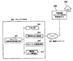
- FIG. 9 is a diagram showing an example of the entire system configuration according to the present embodiment.
- a grid operation system 51 and a customer cooperation server 52 are added, and the consumer energy management apparatus is changed to a grid cooperation type consumer energy management apparatus 220.
- the customer cooperation server 52 is connected to the system operation system 51 and the system cooperation type consumer energy management device 52 through the communication network 60.
- the grid operation system 51 monitors the state of the power system and performs various controls for stably supplying power to consumers with high efficiency.
- distribution control for the purpose of maintaining the voltage of each point in the distribution system within the specified range, distribution control for operating various voltage regulators on the distribution system and maintaining the frequency of the power system within the specified range.
- the purpose is to perform supply and demand control that adjusts the output of each generator so that the total demand and total power generation of the entire power system are balanced.
- the grid operation system 51 predicts the status of the power system on the next day using the status monitoring data of the power system.
- the state of the power system to be predicted includes the demand amount and voltage state at each point of the distribution system, and the total demand amount and total power generation state of the entire power system.
- the customer cooperation server 52 acquires the prediction result of the power system state of the next day from the grid operation system 51, and the demand forecast value of the power receiving point of the customer 200 in which the grid cooperative consumer energy management device 220 is installed, The voltage predicted value is extracted, and further, the supply / demand balance amount prediction value of the next day is acquired from the consumer energy management device 220, and the demand / supply balance amount prediction value is subtracted from the demand prediction value to obtain the value as the demand amount increase target value. .
- the demand increase target value becomes negative, it is replaced with 0.
- the system cooperative local energy production / consumption operation is started in the system cooperative consumer energy management device 220. Send a signal.
- the grid coordinated local production for local consumption start signal includes the demand increase target value.
- the customer 200 receives solar light and converts it into electric power, a photovoltaic power generation facility 211, a storage battery 212 that is a facility capable of storing and taking out electricity, and heating water using electricity to supply hot water.
- An electric water heater 213 which is a facility to be generated and stored in a hot water storage tank and a power load device 214 are provided.
- the grid cooperative consumer energy management apparatus 220 outputs a local production / local consumption start signal from the consumer cooperation server 52 to the input / output unit 236. And controls the equipment in the customer 200 according to the local production for local consumption activation signal.
- FIG. 10 is a functional block diagram of the grid cooperative customer energy management apparatus 220.
- the system cooperation type consumer energy management device 220 includes a system cooperation type local production for local consumption control unit 221 instead of the local production for local consumption control unit 121 of the customer energy management device 100 of FIG.
- the configuration of the grid-coordinated consumer energy management device 220 will be briefly described.
- the solar power surplus power prediction unit 225 and the hot water demand prediction unit 226 are provided.
- the consumer energy management device 220 includes a photovoltaic power generation state monitoring unit 227, a storage battery state monitoring unit 228, a storage battery charge / discharge control unit 229, an electric water heater state monitoring unit 230, and an electric water heater heat storage control unit 231.
- the system coordinating type local production for local consumption control unit 221 is a system coordinated local production for local consumption control signal via the input / output unit 236.
- the following processing is performed until a stop signal is received again. That is, the start signal for suppressing the heat storage operation of the electric water heater 213 is sent to the electric water heater heat storage control unit 231 at night.
- This heat storage operation suppression start signal includes suppression rate data, and the value of the suppression rate is set by the same process as in the first embodiment.
- the following processing is performed according to the reception status of the grid coordinated local production for local consumption activation signal and the local production for local consumption control activation signal.
- the system cooperation type local production for local consumption operation system more reliably avoids the generation of solar power generation at the customer end from being suppressed by the system state such as voltage, and reduces the amount of power generation. It is possible to increase power generation and consumption with lower carbon and more efficient.
- the example of 3rd Embodiment is an example made into the community local production for local consumption operation system in which a consumer energy management apparatus operate
- FIG. 11 is a diagram showing an example of the overall configuration according to the present embodiment.
- a community energy management device 390 is added, and the consumer energy management device is changed to a community-compatible consumer energy management device 350.
- the community energy management device 390 is an energy management device installed in the community center 380, and is connected to the community-compatible consumer energy management devices 314, 322, and 350 of a plurality of consumers in the region via the communication network 331.
- the community-compatible consumer energy management apparatus 314 is an energy management apparatus installed in the consumer 310 (school 311), and controls the storage battery 312 and the electric water heater 313.
- the energy management device 322 is an energy management device of a consumer 320 that includes an electric water heater 320 (not provided with a solar power generation facility).
- the community-compatible consumer energy management apparatus 350 included in the consumer 340 is requested according to a control signal from the community energy management apparatus 390. It has a function of controlling devices in the house 340.
- the consumer 340 is a consumer in which all of the storage battery 342, the electric water heater 343, and the solar power generation facility 342 are installed.
- FIG. 12 is a functional block diagram of the community energy management apparatus 390 installed in the community center 380.
- the community energy management device 390 includes an input / output unit 392, a customer energy management device communication unit 393, a customer data management unit 395, a community state monitoring unit 394, and a community local production for local consumption control unit 391. .
- the input / output unit 392 is an external interface through which a user or an external device inputs data or outputs data to the user or external device.
- the customer energy management device communication unit 393 controls communication for the community energy management device 390 to exchange data with each customer energy management device.
- the customer data management unit 395 stores and manages the installation status and specification data of each device at the consumer end, which is given from the user or an external device via the input / output unit 392, and, at any time, the customer energy management device communication unit Via 392, each community-compatible consumer energy management device 350 in the region is accessed, and the data on the operation status of each device at the consumer end and the local production for local consumption control by the consumer energy management device 350, etc. Collect and store the data.
- the specification data of the consumer-end equipment includes specification data related to the photovoltaic power generation facility, storage battery, and electric water heater described in the first embodiment.
- the community state monitoring unit 394 monitors the supply and demand balance state in the community, collects and aggregates the supply and demand balance amount of each consumer from the community-compatible consumer energy management device of each consumer, Calculate as the balance between supply and demand.
- the community local production for local consumption control unit 391 When the community local production for local consumption control unit 391 receives a community local production for local consumption activation signal from the outside such as a user via the input / output unit, the community local production for local consumption control unit 391 periodically obtains the total supply and demand balance in the community from the community state monitoring unit during the daytime. , If this falls below the reference value of the total supply and demand balance in the community, which is a predetermined reference value, the demand for starting local production for local consumption control and the amount of adjustment for each consumer are calculated, and each demand determined to start local production for local consumption control A community local pond consumption control activation signal is transmitted to the community-compatible consumer energy management apparatus 350 of the house via the consumer energy management apparatus communication unit.
- the community local production for local consumption control activation signal includes adjustment amount data for each consumer.
- the selection may be made in order from the consumers with the largest value of the average COP ⁇ average heat dissipation loss of the electric water heater. In this case, to reduce the heat dissipation loss when storing hot water that will be stored more than usual at the customer's end longer than usual, and to improve the energy efficiency of the entire community. Can do.
- FIG. 13 is a functional block diagram of the community-compatible consumer energy management device 350.
- the community-compatible consumer energy management device 350 includes a community-compatible local production / local consumption control unit and a local production / local consumption control integration unit in addition to the configuration of the consumer energy management device of FIG. 2 described in the first embodiment. The difference is that the processing of the local production for local consumption control unit is changed accordingly.
- FIG. 13 is a functional block diagram of the community-compatible consumer energy management device 350.
- the community-compatible consumer energy management device 350 includes a community-compatible local production / local consumption control unit and a local production / local consumption control integration
- the local production for local consumption control unit 353 transmits the control signal for adjusting the heat storage operation of the electric water heater to the electric water heater heat storage control unit.
- the data is sent to the control integration unit 351.
- the local production for local consumption control unit 351 When the community local production for local consumption control unit 352 receives the community local production for local consumption start signal via the input / output unit 368, the local production for local consumption control unit 351 sends an activation signal for the heat storage operation of the electric water heater 343 to the local production for local consumption control integration unit 351.
- the heat storage operation start signal includes power consumption target value data, and the value is the value of the adjustment amount received by the community local production for local consumption start signal.
- the local production for local consumption control integration unit 351 receives the control signal from only one of the local production for local consumption control unit 353 and the community-based local production for local consumption control unit 352, and if it receives from both, The heat storage activation control signal is prioritized over the heat accumulation suppression control signal, and in the case of both the heat accumulation activation control signals, the one with the larger power consumption target value is adopted, and the electric water heater heat accumulation suppression unit 363 is adopted.
- the control signal of heat storage suppression and heat storage start is sent.
- the community-compatible consumer energy management device 350 includes a photovoltaic power generation amount prediction unit 354, a power demand prediction unit 355, a demand balance prediction unit 356, a solar power surplus power prediction unit 357, and a hot water demand prediction unit 358.
- the photovoltaic power generation state monitoring unit 359, the storage battery state monitoring unit 360, the storage battery charge / discharge control unit 361, the electric water heater state monitoring unit 362, the electric water heater heat storage control unit 363, and the power demand state monitoring unit 364 The next day demand forecast table data storage unit 365, a device specification data management unit 366, a customer performance database 367, and an input / output unit 368 are provided.
- the local production / local consumption control integration unit 351, the community-based local production / local consumption control unit 352, and the local production / local consumption control unit 353 other than the local production / local consumption control integration unit 351 described above are the units of the energy management device 120 described in the first embodiment. Similar processing is performed.
- FIG. 14 is a diagram showing a state where solar power generation surplus power is absorbed by the electric water heater 343.
- FIG. 14 is a diagram similar to FIG. 8 described in the first embodiment.
- Photovoltaic power that cannot be absorbed by a single consumer can be absorbed by another consumer's electric water heater or storage battery.
- the solar power generation surplus electric power of another consumer can be combined and the electric water heater's rating or more can be secured.
- FIG. 15 to FIG. 16 portions corresponding to FIG. 1 to FIG. 14 described in the first, second and third embodiments are denoted by the same reference numerals.
- An example of the fourth embodiment is a system-coordinated community local production for local consumption in which a consumer energy management apparatus operates in cooperation with a plurality of consumers, and operates in cooperation with a power system operation system. This is an example of an operational system.
- FIG. 15 is a diagram showing an example of the overall configuration according to the present embodiment.
- the system configuration of FIG. 15 in the fourth embodiment is a system configuration in which the system configuration of the second embodiment shown in FIG. 9 is combined with the system configuration of the third embodiment shown in FIG. It is.
- the community energy management device is configured as a grid-coordinated community energy management device 490.
- the devices 414, 422, and 450 are communicably connected via a communication network 431 and the like, and operate in cooperation with each other.
- the customer cooperation server 510 performs the same processing as the customer cooperation server 52 described in the second embodiment.
- the grid-coordinated community-based community energy of the community center 480 is used as the grid coordination community local production for local consumption activation signal. It transmits to the management apparatus 490.
- the grid cooperative community local production for local consumption activation signal includes the demand increase target value as in the second embodiment.
- the community-compatible customer energy management device 450 performs the same processing with the same configuration as the community-compatible customer energy management device 350 of the third embodiment. That is, the community-compatible consumer energy management device 450 installed in the consumer 440 controls the storage battery 442 and the electric water heater 443. The consumer 440 also includes a power load device 444.
- the customer 410 which is the school 411 is equipped with the storage battery 412 and the electric water heater 413, and is controlled by the community-compatible consumer energy management apparatus 414.
- the community-compatible consumer energy management device 422 is an energy management device of the consumer 420 that includes the electric water heater 420 (not provided with solar power generation facilities).
- FIG. 16 is a functional block diagram of the system cooperation type community energy management device 490.
- the grid-coordinated community energy management device 490 includes a grid-coordinated community local production for local consumption control unit and a community local production for local consumption control integration unit 491. The difference is that the processing of the local production for local consumption control unit 492 is changed.
- Other configurations of the community energy management device 390 include an input / output unit 497, a consumer energy management device communication unit 494, a customer data management unit 496, a community state monitoring unit 495, a system-coordinated community local production for local consumption And a control unit 496.
- the grid cooperative community local production for local consumption control unit 493 receives either or both of the grid cooperative community local production for local consumption start signal and the community local production for local consumption start signal via the input / output unit 497, the following is periodically performed.
- Process determine the consumers to be activated for grid-coordinated community local production for local consumption control and their adjustment amount, and communicate with each customer's community-compatible consumer energy management device 450, etc.
- a community local production for local consumption control activation signal is transmitted via the unit 494.
- the community local production for local consumption control activation signal includes adjustment amount data for each consumer. This process is repeatedly executed until a stop signal is received from the outside such as a user via the input / output unit 497.
- a community state monitoring unit 495 obtains the total supply / demand balance in the community, and subtracts this from the total supply / demand balance reference in the community. If the obtained value is larger than the previously calculated in-community solar power surplus power amount, the value of the in-community solar power surplus power amount is updated with that value.
- Electric water heater power consumption is selected in order from the consumers with the largest average COP of electricity water heaters The possible amount is totaled, and the selection is finished when the surplus amount of solar power in the community is exceeded.
- ⁇ Set the adjustment amount of the selected consumer by the electric water heater power consumption possible amount.
- control by system operation and cooperative control in the community are performed in cooperation, so that more solar power surplus power can be absorbed and more efficient operation becomes possible.
Landscapes
- Engineering & Computer Science (AREA)
- Power Engineering (AREA)
- Supply And Distribution Of Alternating Current (AREA)
- Heat-Pump Type And Storage Water Heaters (AREA)
- Charge And Discharge Circuits For Batteries Or The Like (AREA)
Abstract
Lorsqu'un équipement de stockage d'énergie connecté à un générateur électrique photovoltaïque (PV) est connecté à l'extrémité d'un consommateur, on obtient un fonctionnement optimal de l'équipement de stockage d'énergie afin de rendre maximale la quantité d'énergie produite par le générateur électrique photovoltaïque. Un système de gestion d'énergie, comprenant une unité de gestion qui contrôle les pertes dans les accumulateurs de stockage et les pertes par dissipation thermique dans un chauffe-eau électrique, réalise une commande dans laquelle un équipement de stockage d'énergie à faibles pertes est utilisé en priorité pour absorber la quantité d'énergie photovoltaïque produite. Le système de gestion d'énergie est doté d'une unité de calcul du fonctionnement du réseau électrique, destinée à estimer la distribution de la tension dans le système de distribution électrique ou le solde du bilan offre-demande du système de réseau électrique dans son ensemble le lendemain, en utilisant des données de surveillance de l'état du réseau électrique, et il calcule une valeur de consigne de l'augmentation de la demande qui est nécessaire pour prévenir une réduction de la quantité d'énergie photovoltaïque produite à l'extrémité du consommateur, en utilisant la distribution de la tension sur le système de distribution électrique ou le solde du bilan offre-demande du lendemain ; il réalise également une commande du type coopération avec le réseau, qui commande l'équipement de stockage d'énergie de manière à ce que la valeur de consigne d'augmentation de la demande soit satisfaite à l'extrémité du consommateur. Par ailleurs, le système de gestion d'énergie réalise une commande dans laquelle, lorsque la capacité de l'équipement de stockage d'énergie dans les locaux du consommateur est insuffisante pour absorber la quantité d'énergie photovoltaïque qui doit y être produite, la quantité d'énergie photovoltaïque à produire est absorbée par l'équipement de stockage d'énergie d'autres consommateurs.
Priority Applications (1)
| Application Number | Priority Date | Filing Date | Title |
|---|---|---|---|
| JP2012508011A JP5576476B2 (ja) | 2010-03-29 | 2010-09-03 | エネルギーマネジメントシステム、エネルギーマネジメント装置及びエネルギーマネジメント方法 |
Applications Claiming Priority (2)
| Application Number | Priority Date | Filing Date | Title |
|---|---|---|---|
| JP2010-074822 | 2010-03-29 | ||
| JP2010074822 | 2010-03-29 |
Publications (1)
| Publication Number | Publication Date |
|---|---|
| WO2011121815A1 true WO2011121815A1 (fr) | 2011-10-06 |
Family
ID=44511688
Family Applications (1)
| Application Number | Title | Priority Date | Filing Date |
|---|---|---|---|
| PCT/JP2010/065176 WO2011121815A1 (fr) | 2010-03-29 | 2010-09-03 | Système de gestion d'énergie, appareil de gestion d'énergie et procédé de gestion d'énergie |
Country Status (5)
| Country | Link |
|---|---|
| US (1) | US8560135B2 (fr) |
| EP (1) | EP2375528B1 (fr) |
| JP (1) | JP5576476B2 (fr) |
| CN (1) | CN102208882B (fr) |
| WO (1) | WO2011121815A1 (fr) |
Cited By (14)
| Publication number | Priority date | Publication date | Assignee | Title |
|---|---|---|---|---|
| JP2012005168A (ja) * | 2010-06-14 | 2012-01-05 | Daiwa House Industry Co Ltd | エネルギーマネジメントシステム及びエネルギーマネジメント方法 |
| CN103207572A (zh) * | 2012-01-13 | 2013-07-17 | 株式会社日立制作所 | It 设备与冷却设备的协同控制系统以及协同控制方法 |
| JP2013146140A (ja) * | 2012-01-13 | 2013-07-25 | Chugoku Electric Power Co Inc:The | 負荷管理システムおよび負荷管理方法 |
| JP2015106937A (ja) * | 2013-11-28 | 2015-06-08 | 三菱電機株式会社 | 太陽光発電システム |
| JP2015534437A (ja) * | 2012-09-28 | 2015-11-26 | エンリッチメント テクノロジー カンパニー リミテッドEnrichment Technology Company Ltd. | エネルギー貯蔵システム |
| WO2016038994A1 (fr) * | 2014-09-12 | 2016-03-17 | 株式会社東芝 | Dispositif de création de plan de fonctionnement de dispositif, procédé de création de plan de fonctionnement de dispositif, et programme de création de plan de fonctionnement de dispositif de stockage sur support d'enregistrement |
| JP2016039652A (ja) * | 2014-08-05 | 2016-03-22 | 三菱電機株式会社 | 配電系統管理装置、配電系統システムおよび配電系統管理方法 |
| JP2016171679A (ja) * | 2015-03-13 | 2016-09-23 | パナソニックIpマネジメント株式会社 | 制御装置およびそれを利用した配電システム |
| US9478986B2 (en) | 2011-08-23 | 2016-10-25 | Hitachi, Ltd. | Load leveling system of power system |
| WO2017109935A1 (fr) * | 2015-12-25 | 2017-06-29 | 三菱電機株式会社 | Dispositif de gestion et système de gestion |
| JP2018115826A (ja) * | 2017-01-20 | 2018-07-26 | 株式会社コロナ | 太陽光発電装置連携貯湯式給湯システム及び太陽光発電装置連携貯湯式給湯装置 |
| JPWO2017149618A1 (ja) * | 2016-02-29 | 2018-08-30 | 日本電気株式会社 | 制御装置、発電制御装置、制御方法、システム、及び、プログラム |
| WO2020071580A1 (fr) * | 2018-10-05 | 2020-04-09 | 주식회사 브리콘 | Système de production d'énergie thermoélectrique de cogénération utilisant un collecteur solaire |
| JP7452451B2 (ja) | 2021-02-01 | 2024-03-19 | トヨタ自動車株式会社 | サーバ、電力管理方法 |
Families Citing this family (49)
| Publication number | Priority date | Publication date | Assignee | Title |
|---|---|---|---|---|
| US8204633B2 (en) * | 2008-07-01 | 2012-06-19 | Carina Technology, Inc. | Water heater demand side management system |
| EP2685417A4 (fr) | 2011-03-07 | 2014-12-31 | Hitachi Ltd | Système, procédé et programme informatique pour la gestion de la consommation d'énergie |
| US8768528B2 (en) * | 2011-05-16 | 2014-07-01 | Vcharge, Inc. | Electrical thermal storage with edge-of-network tailored energy delivery systems and methods |
| JP2012252580A (ja) * | 2011-06-03 | 2012-12-20 | Sony Corp | 電力制御装置、電力管理装置および電力管理システム |
| CN102933915A (zh) * | 2011-06-06 | 2013-02-13 | 松下电器产业株式会社 | 热泵的运转方法及热泵系统 |
| JP5990897B2 (ja) * | 2011-11-25 | 2016-09-14 | ソニー株式会社 | 電力制御装置、送電装置、および電力制御システム |
| JP5603318B2 (ja) | 2011-12-22 | 2014-10-08 | 株式会社日立製作所 | 電力需要調整システム、装置、および方法 |
| DE102011090141A1 (de) * | 2011-12-29 | 2013-07-04 | Werner Schmid | Verfahren und Vorrichtung zur Nutzung elektrischer Energie einer an ein Hausstromnetz angeschlossenen Einrichtung zur Erzeugung erneuerbarer elektrischer Energie |
| JP5872298B2 (ja) * | 2012-01-13 | 2016-03-01 | 株式会社日立製作所 | 電力供給システムおよび外部へ電力供給可能な自動車制御装置 |
| JP5806132B2 (ja) * | 2012-01-23 | 2015-11-10 | 京セラ株式会社 | 発電量予測装置、発電量予測補正方法、および自然エネルギー発電システム |
| US20150073737A1 (en) * | 2012-04-20 | 2015-03-12 | Tatsuki Inuzuka | Power monitoring apparatus and power monitoring method |
| GB2502813B (en) * | 2012-06-07 | 2015-11-18 | Bmshome Ltd | Controlling the heating of rooms |
| US9429924B2 (en) * | 2012-06-26 | 2016-08-30 | International Business Machines Corporation | Controlling power generators and chillers |
| JP5882156B2 (ja) * | 2012-07-23 | 2016-03-09 | 株式会社デンソー | 電力制御装置 |
| US20140129042A1 (en) * | 2012-11-07 | 2014-05-08 | Dorazio Enterprises, Inc. | Community Based Energy Management System |
| US9912157B2 (en) | 2013-03-04 | 2018-03-06 | Nec Corporation | Energy management system and energy management method |
| JP5998081B2 (ja) | 2013-03-08 | 2016-09-28 | 株式会社日立製作所 | 電力需要調整システム及び需要調整実行システム |
| JPWO2014167830A1 (ja) * | 2013-04-09 | 2017-02-16 | 日本電気株式会社 | 電力制御システム |
| CZ304509B6 (cs) * | 2013-04-25 | 2014-06-04 | Unites Systems A.S. | Systém pro hospodaření s elektrickou energií vyrobenou fotovoltaickými články |
| JP6156493B2 (ja) * | 2013-05-30 | 2017-07-05 | 東芝三菱電機産業システム株式会社 | 電力管理装置 |
| WO2015018465A2 (fr) * | 2013-08-05 | 2015-02-12 | Nec Europe Ltd. | Procédé, système et moyen de régulation pour équilibrage de charge entre nœuds locaux |
| CN105637439B (zh) * | 2013-09-30 | 2019-07-09 | 施耐德电气美国股份有限公司 | 数据获取的系统和方法 |
| WO2015087391A1 (fr) * | 2013-12-10 | 2015-06-18 | 中国電力株式会社 | Dispositif de commande de charge/décharge, et programme |
| KR101795745B1 (ko) * | 2014-02-17 | 2017-11-08 | 한국전자통신연구원 | 다중상황 기반 에너지 관리장치 및 관리방법 |
| EP3247016B1 (fr) * | 2015-01-16 | 2022-06-08 | Mitsubishi Electric Corporation | Dispositif de gestion d'énergie électrique |
| FR3033918A1 (fr) * | 2015-03-18 | 2016-09-23 | Thales Sa | Procede de gestion d'energie |
| WO2016176727A1 (fr) * | 2015-05-01 | 2016-11-10 | The University Of Sydney | Planification d'opérations de production d'énergie, de stockage d'énergie et de charge d'énergie |
| US10817789B2 (en) * | 2015-06-09 | 2020-10-27 | Opower, Inc. | Determination of optimal energy storage methods at electric customer service points |
| US11009250B2 (en) | 2015-06-30 | 2021-05-18 | Emerson Climate Technologies Retail Solutions, Inc. | Maintenance and diagnostics for refrigeration systems |
| US10240836B2 (en) * | 2015-06-30 | 2019-03-26 | Emerson Climate Technologies Retail Solutions, Inc. | Energy management for refrigeration systems |
| WO2017109947A1 (fr) * | 2015-12-25 | 2017-06-29 | 三菱電機株式会社 | Dispositif de commande, procédé de commande pour chauffe-eau et programme |
| WO2017154116A1 (fr) * | 2016-03-08 | 2017-09-14 | 日本電気株式会社 | Dispositif de régulation d'électricité, système de régulation d'électricité, procédé de régulation d'électricité et programme |
| US20180006526A1 (en) * | 2016-07-02 | 2018-01-04 | Thad Paul Sundrla | Kinetic energy to electricity system and method |
| SG11201900917SA (en) * | 2016-08-03 | 2019-02-27 | Zeco Systems Inc | Distributed resource electrical demand forecasting system and method |
| CN106374831B (zh) * | 2016-09-26 | 2017-12-29 | 国电南瑞科技股份有限公司 | 一种带有发电预测的分布式光伏监控系统及监控方法 |
| US10627146B2 (en) | 2016-10-17 | 2020-04-21 | Emerson Climate Technologies, Inc. | Liquid slugging detection and protection |
| CN106711997B (zh) * | 2016-11-28 | 2019-07-16 | 浙江大学 | 一种基于碳排放电价的电力用户碳排放成本分摊方法 |
| JP7073639B2 (ja) * | 2017-06-22 | 2022-05-24 | 住友電気工業株式会社 | 電力制御指示生成装置、コンピュータプログラム及び電力制御指示生成方法 |
| JP6978742B2 (ja) * | 2017-09-25 | 2021-12-08 | 四国電力株式会社 | 制御情報送信によるブロック毎の貯湯式電気給湯器運用システム |
| JP7123711B2 (ja) * | 2018-09-19 | 2022-08-23 | 大和ハウス工業株式会社 | システム |
| CN109494801A (zh) * | 2018-12-25 | 2019-03-19 | 航天柏克(广东)科技有限公司 | 一种离并网光伏逆变系统 |
| CN109945464A (zh) * | 2019-01-09 | 2019-06-28 | 青岛海尔空调器有限总公司 | 能量存储站的能量分享方法 |
| US10976067B2 (en) * | 2019-06-14 | 2021-04-13 | Albasolar S.R.L. | Exploitation of a photovoltaic system coupled to a joint water boiler-air/air heat pump air conditioning system |
| JP7345408B2 (ja) * | 2020-01-29 | 2023-09-15 | 株式会社日立製作所 | エネルギー管理システムおよびエネルギー管理方法 |
| CN112700084A (zh) * | 2020-12-08 | 2021-04-23 | 珠海格力电器股份有限公司 | 竞争式储能分配方法、装置、控制器和社区储能分配系统 |
| CN116783609A (zh) * | 2021-02-10 | 2023-09-19 | 日产自动车株式会社 | 充放电损失降低方法以及充放电损失降低装置 |
| CN113865112B (zh) * | 2021-11-01 | 2022-10-11 | 国网吉林省电力有限公司经济技术研究院 | 可调节功耗的电热水器、系统及控制方法 |
| CN114498702B (zh) * | 2022-01-26 | 2023-03-24 | 南京清电物联科技有限公司 | 一种基于能源路由器的微电网能源管理方法和系统 |
| CN115622100B (zh) * | 2022-05-12 | 2023-07-28 | 深圳市海雷新能源有限公司 | 一种使用光伏储能电池的企业用电分配监测系统及方法 |
Citations (3)
| Publication number | Priority date | Publication date | Assignee | Title |
|---|---|---|---|---|
| JP2000055479A (ja) * | 1998-08-11 | 2000-02-25 | Shiro Tsuji | 太陽光発電温水装置 |
| JP2004208426A (ja) * | 2002-12-25 | 2004-07-22 | Chugoku Electric Power Co Inc:The | 直流連系による家庭用分散型電源装置及びその制御方法 |
| JP2006304402A (ja) * | 2005-04-15 | 2006-11-02 | Nippon Telegr & Teleph Corp <Ntt> | 分散型エネルギーシステムの制御装置、制御方法、プログラム、および記録媒体 |
Family Cites Families (13)
| Publication number | Priority date | Publication date | Assignee | Title |
|---|---|---|---|---|
| JPS6188731A (ja) * | 1984-10-04 | 1986-05-07 | シャープ株式会社 | 充放電制御装置 |
| JPH08275390A (ja) * | 1995-03-29 | 1996-10-18 | Canon Inc | 充放電制御方法、充放電制御装置及び該充放電制御装置を有する発電システム |
| JP2000324716A (ja) * | 1999-04-30 | 2000-11-24 | Haneda Hume Pipe Co Ltd | 太陽電池装置 |
| JP2001238366A (ja) * | 2000-02-28 | 2001-08-31 | Sekisui Chem Co Ltd | 電力供給装置 |
| US6630622B2 (en) * | 2001-01-15 | 2003-10-07 | Annemarie Hvistendahl Konold | Combined solar electric power and liquid heat transfer collector panel |
| JP4149800B2 (ja) * | 2002-12-26 | 2008-09-17 | 三機工業株式会社 | 地中管路への通信ケーブル敷設用管内作業装置及び通信ケーブル敷設方法 |
| US7274975B2 (en) * | 2005-06-06 | 2007-09-25 | Gridpoint, Inc. | Optimized energy management system |
| JP4600235B2 (ja) * | 2005-09-29 | 2010-12-15 | 株式会社日立製作所 | コジェネレーション設備制御システム及びコジェネレーション設備制御方法 |
| US8855829B2 (en) * | 2007-01-03 | 2014-10-07 | Gridpoint, Inc. | Method for controlling energy resources |
| JP5211534B2 (ja) * | 2007-04-03 | 2013-06-12 | セイコーエプソン株式会社 | 発電機能付き電子時計 |
| US8204633B2 (en) * | 2008-07-01 | 2012-06-19 | Carina Technology, Inc. | Water heater demand side management system |
| JP4713623B2 (ja) * | 2008-09-25 | 2011-06-29 | 株式会社日立製作所 | 充放電管理装置 |
| JP5255462B2 (ja) | 2009-01-13 | 2013-08-07 | 株式会社日立製作所 | 電力需給運用管理サーバ、および電力需給運用管理システム |
-
2010
- 2010-09-03 WO PCT/JP2010/065176 patent/WO2011121815A1/fr active Application Filing
- 2010-09-03 JP JP2012508011A patent/JP5576476B2/ja active Active
-
2011
- 2011-02-11 EP EP11001149.1A patent/EP2375528B1/fr active Active
- 2011-02-16 US US13/028,388 patent/US8560135B2/en active Active
- 2011-02-18 CN CN2011100417904A patent/CN102208882B/zh active Active
Patent Citations (3)
| Publication number | Priority date | Publication date | Assignee | Title |
|---|---|---|---|---|
| JP2000055479A (ja) * | 1998-08-11 | 2000-02-25 | Shiro Tsuji | 太陽光発電温水装置 |
| JP2004208426A (ja) * | 2002-12-25 | 2004-07-22 | Chugoku Electric Power Co Inc:The | 直流連系による家庭用分散型電源装置及びその制御方法 |
| JP2006304402A (ja) * | 2005-04-15 | 2006-11-02 | Nippon Telegr & Teleph Corp <Ntt> | 分散型エネルギーシステムの制御装置、制御方法、プログラム、および記録媒体 |
Cited By (17)
| Publication number | Priority date | Publication date | Assignee | Title |
|---|---|---|---|---|
| JP2012005168A (ja) * | 2010-06-14 | 2012-01-05 | Daiwa House Industry Co Ltd | エネルギーマネジメントシステム及びエネルギーマネジメント方法 |
| US9478986B2 (en) | 2011-08-23 | 2016-10-25 | Hitachi, Ltd. | Load leveling system of power system |
| CN103207572A (zh) * | 2012-01-13 | 2013-07-17 | 株式会社日立制作所 | It 设备与冷却设备的协同控制系统以及协同控制方法 |
| JP2013146140A (ja) * | 2012-01-13 | 2013-07-25 | Chugoku Electric Power Co Inc:The | 負荷管理システムおよび負荷管理方法 |
| JP2015534437A (ja) * | 2012-09-28 | 2015-11-26 | エンリッチメント テクノロジー カンパニー リミテッドEnrichment Technology Company Ltd. | エネルギー貯蔵システム |
| JP2015106937A (ja) * | 2013-11-28 | 2015-06-08 | 三菱電機株式会社 | 太陽光発電システム |
| JP2016039652A (ja) * | 2014-08-05 | 2016-03-22 | 三菱電機株式会社 | 配電系統管理装置、配電系統システムおよび配電系統管理方法 |
| WO2016038994A1 (fr) * | 2014-09-12 | 2016-03-17 | 株式会社東芝 | Dispositif de création de plan de fonctionnement de dispositif, procédé de création de plan de fonctionnement de dispositif, et programme de création de plan de fonctionnement de dispositif de stockage sur support d'enregistrement |
| EP3193421A4 (fr) * | 2014-09-12 | 2018-02-21 | Kabushiki Kaisha Toshiba | Dispositif de création de plan de fonctionnement de dispositif, procédé de création de plan de fonctionnement de dispositif, et programme de création de plan de fonctionnement de dispositif de stockage sur support d'enregistrement |
| JP2016171679A (ja) * | 2015-03-13 | 2016-09-23 | パナソニックIpマネジメント株式会社 | 制御装置およびそれを利用した配電システム |
| WO2017109935A1 (fr) * | 2015-12-25 | 2017-06-29 | 三菱電機株式会社 | Dispositif de gestion et système de gestion |
| JPWO2017109935A1 (ja) * | 2015-12-25 | 2018-03-22 | 三菱電機株式会社 | 管理装置、及び、管理システム |
| JPWO2017149618A1 (ja) * | 2016-02-29 | 2018-08-30 | 日本電気株式会社 | 制御装置、発電制御装置、制御方法、システム、及び、プログラム |
| US10855080B2 (en) | 2016-02-29 | 2020-12-01 | Nec Corporation | Systems and methods for generating power generation suppression control information by a control device |
| JP2018115826A (ja) * | 2017-01-20 | 2018-07-26 | 株式会社コロナ | 太陽光発電装置連携貯湯式給湯システム及び太陽光発電装置連携貯湯式給湯装置 |
| WO2020071580A1 (fr) * | 2018-10-05 | 2020-04-09 | 주식회사 브리콘 | Système de production d'énergie thermoélectrique de cogénération utilisant un collecteur solaire |
| JP7452451B2 (ja) | 2021-02-01 | 2024-03-19 | トヨタ自動車株式会社 | サーバ、電力管理方法 |
Also Published As
| Publication number | Publication date |
|---|---|
| US20110238232A1 (en) | 2011-09-29 |
| CN102208882B (zh) | 2013-11-13 |
| EP2375528A3 (fr) | 2016-11-09 |
| EP2375528B1 (fr) | 2018-04-25 |
| CN102208882A (zh) | 2011-10-05 |
| US8560135B2 (en) | 2013-10-15 |
| JPWO2011121815A1 (ja) | 2013-07-04 |
| JP5576476B2 (ja) | 2014-08-20 |
| EP2375528A2 (fr) | 2011-10-12 |
Similar Documents
| Publication | Publication Date | Title |
|---|---|---|
| JP5576476B2 (ja) | エネルギーマネジメントシステム、エネルギーマネジメント装置及びエネルギーマネジメント方法 | |
| JP5204819B2 (ja) | エネルギマネジメントシステムおよびエネルギマネジメント方法 | |
| JP6168564B2 (ja) | 分散型エネルギー源から、電気エネルギーを供給するための方法及び発電システム | |
| US9099893B2 (en) | Power control device for a power grid, comprising a control unit for controlling an energy flow between the power generation unit, the energy storage unit, the consumer unit and/or the power grid | |
| US9557068B2 (en) | Heat pump hot-water supply system | |
| JP5107345B2 (ja) | モジュール式エネルギー制御システム | |
| JP5584763B2 (ja) | 直流配電システム | |
| US20110082598A1 (en) | Electrical Power Time Shifting | |
| US11689118B2 (en) | Converter with power management system for household users to manage power between different loads including their electric vehicle | |
| JP2008141926A (ja) | 家庭用電力蓄積装置、車載用電力蓄積装置、電力供給・蓄積システム及び蓄電制御方法 | |
| WO2013030937A1 (fr) | Système de régulation de puissance électrique régionale et procédé de régulation de puissance électrique régionale | |
| CN107210606B (zh) | 能源管理的方法 | |
| JP6821904B2 (ja) | 電力システム | |
| JP2013017284A (ja) | 電力制御システム、電気機器、および充放電制御部 | |
| WO2015001767A1 (fr) | Dispositif de commande et système de gestion d'énergie | |
| JP2013093981A (ja) | 電動車両の充放電システム | |
| EP3689667A1 (fr) | Station de charge de véhicule électrique à gestion d'énergie | |
| JP2017195752A (ja) | 電力制御システムおよび電力制御方法 | |
| JP2020068555A (ja) | 電力管理システム及び集合住宅 | |
| JP7260994B2 (ja) | 電力制御システム | |
| JP2022054168A (ja) | 電力制御装置および電力制御方法 | |
| Moyse et al. | Just add batteries: Considerations for hybrid systems |
Legal Events
| Date | Code | Title | Description |
|---|---|---|---|
| 121 | Ep: the epo has been informed by wipo that ep was designated in this application |
Ref document number: 10848988 Country of ref document: EP Kind code of ref document: A1 |
|
| WWE | Wipo information: entry into national phase |
Ref document number: 2012508011 Country of ref document: JP |
|
| NENP | Non-entry into the national phase |
Ref country code: DE |
|
| 122 | Ep: pct application non-entry in european phase |
Ref document number: 10848988 Country of ref document: EP Kind code of ref document: A1 |