WO2011121669A1 - ピストン型圧縮機 - Google Patents
ピストン型圧縮機 Download PDFInfo
- Publication number
- WO2011121669A1 WO2011121669A1 PCT/JP2010/002388 JP2010002388W WO2011121669A1 WO 2011121669 A1 WO2011121669 A1 WO 2011121669A1 JP 2010002388 W JP2010002388 W JP 2010002388W WO 2011121669 A1 WO2011121669 A1 WO 2011121669A1
- Authority
- WO
- WIPO (PCT)
- Prior art keywords
- shaft
- crank chamber
- suction
- chamber
- working fluid
- Prior art date
- Legal status (The legal status is an assumption and is not a legal conclusion. Google has not performed a legal analysis and makes no representation as to the accuracy of the status listed.)
- Ceased
Links
Images


Classifications
-
- F—MECHANICAL ENGINEERING; LIGHTING; HEATING; WEAPONS; BLASTING
- F04—POSITIVE - DISPLACEMENT MACHINES FOR LIQUIDS; PUMPS FOR LIQUIDS OR ELASTIC FLUIDS
- F04B—POSITIVE-DISPLACEMENT MACHINES FOR LIQUIDS; PUMPS
- F04B27/00—Multi-cylinder pumps specially adapted for elastic fluids and characterised by number or arrangement of cylinders
- F04B27/08—Multi-cylinder pumps specially adapted for elastic fluids and characterised by number or arrangement of cylinders having cylinders coaxial with, or parallel or inclined to, main shaft axis
- F04B27/0804—Multi-cylinder pumps specially adapted for elastic fluids and characterised by number or arrangement of cylinders having cylinders coaxial with, or parallel or inclined to, main shaft axis having rotary cylinder block
- F04B27/0808—Multi-cylinder pumps specially adapted for elastic fluids and characterised by number or arrangement of cylinders having cylinders coaxial with, or parallel or inclined to, main shaft axis having rotary cylinder block having two or more sets of cylinders or pistons
-
- F—MECHANICAL ENGINEERING; LIGHTING; HEATING; WEAPONS; BLASTING
- F04—POSITIVE - DISPLACEMENT MACHINES FOR LIQUIDS; PUMPS FOR LIQUIDS OR ELASTIC FLUIDS
- F04B—POSITIVE-DISPLACEMENT MACHINES FOR LIQUIDS; PUMPS
- F04B27/00—Multi-cylinder pumps specially adapted for elastic fluids and characterised by number or arrangement of cylinders
- F04B27/08—Multi-cylinder pumps specially adapted for elastic fluids and characterised by number or arrangement of cylinders having cylinders coaxial with, or parallel or inclined to, main shaft axis
- F04B27/10—Multi-cylinder pumps specially adapted for elastic fluids and characterised by number or arrangement of cylinders having cylinders coaxial with, or parallel or inclined to, main shaft axis having stationary cylinders
- F04B27/1009—Distribution members
-
- F—MECHANICAL ENGINEERING; LIGHTING; HEATING; WEAPONS; BLASTING
- F04—POSITIVE - DISPLACEMENT MACHINES FOR LIQUIDS; PUMPS FOR LIQUIDS OR ELASTIC FLUIDS
- F04B—POSITIVE-DISPLACEMENT MACHINES FOR LIQUIDS; PUMPS
- F04B27/00—Multi-cylinder pumps specially adapted for elastic fluids and characterised by number or arrangement of cylinders
- F04B27/08—Multi-cylinder pumps specially adapted for elastic fluids and characterised by number or arrangement of cylinders having cylinders coaxial with, or parallel or inclined to, main shaft axis
- F04B27/10—Multi-cylinder pumps specially adapted for elastic fluids and characterised by number or arrangement of cylinders having cylinders coaxial with, or parallel or inclined to, main shaft axis having stationary cylinders
- F04B27/1036—Component parts, details, e.g. sealings, lubrication
- F04B27/109—Lubrication
-
- F—MECHANICAL ENGINEERING; LIGHTING; HEATING; WEAPONS; BLASTING
- F04—POSITIVE - DISPLACEMENT MACHINES FOR LIQUIDS; PUMPS FOR LIQUIDS OR ELASTIC FLUIDS
- F04B—POSITIVE-DISPLACEMENT MACHINES FOR LIQUIDS; PUMPS
- F04B39/00—Component parts, details, or accessories, of pumps or pumping systems specially adapted for elastic fluids, not otherwise provided for in, or of interest apart from, groups F04B25/00 - F04B37/00
- F04B39/02—Lubrication
- F04B39/0223—Lubrication characterised by the compressor type
- F04B39/023—Hermetic compressors
- F04B39/0238—Hermetic compressors with oil distribution channels
- F04B39/0246—Hermetic compressors with oil distribution channels in the rotating shaft
-
- F—MECHANICAL ENGINEERING; LIGHTING; HEATING; WEAPONS; BLASTING
- F04—POSITIVE - DISPLACEMENT MACHINES FOR LIQUIDS; PUMPS FOR LIQUIDS OR ELASTIC FLUIDS
- F04B—POSITIVE-DISPLACEMENT MACHINES FOR LIQUIDS; PUMPS
- F04B39/00—Component parts, details, or accessories, of pumps or pumping systems specially adapted for elastic fluids, not otherwise provided for in, or of interest apart from, groups F04B25/00 - F04B37/00
- F04B39/04—Measures to avoid lubricant contaminating the pumped fluid
Definitions
- the present invention relates to a piston type compressor having a structure capable of separating oil mixed in a working fluid on a working fluid path in the compressor, and more particularly to a piston type compressor that is used in a vehicle air conditioner and sucked from a suction port.
- the present invention relates to a compressor having a working fluid path that guides a working fluid to a suction chamber via a crank chamber, and discharges the working fluid from a discharge port via the discharge chamber after being compressed by a piston.
- the applicant of the present invention firstly, in the compressor that guides the working fluid from the suction port to the suction chamber via the crank chamber, the shaft direction of the shaft passes through the crank chamber. And at least a side hole that communicates with the shaft hole and that is provided in the radial direction of the shaft and opens into the crank chamber. At least the working fluid that has flowed into the crank chamber is allowed to pass through the shaft hole.
- the oil in the working fluid that is going to flow from the crank chamber to the suction chamber flows through the side hole opened in the crank chamber by utilizing the centrifugal separation action caused by the rotation of the shaft.
- separate is proposed (refer patent document 1).
- the present applicant introduces the working fluid that has flowed into the crank chamber to the suction chamber through the shaft and guides it to the suction chamber, and guides the working fluid sucked from the suction port to the suction chamber without passing through the crank chamber.
- a configuration in which another suction path is provided so that a part of the sucked working fluid passes through the shaft from the crank chamber and is directly guided to the suction chamber see Patent Document 2.
- the present invention has been made in view of such circumstances, and is accommodated in the crank chamber while effectively reducing the outflow of oil to the outside of the compressor by effectively performing the centrifugal separation action by the rotation of the shaft.
- the main object is to provide a piston-type compressor capable of promoting the cooling of internal parts and suppressing the wear of sliding parts such as bearings.
- Another object of the present invention is to remove wear powder when wear occurs at a sliding portion in the crank chamber and to suppress adverse effects caused by the wear powder adhering to the sliding parts.
- the present inventors only have to reduce the flow rate of the working fluid flowing into the shaft from the crank chamber in order to effectively perform the centrifugal separation action by the rotation of the shaft.
- the amount of working fluid supplied to the crank chamber decreases, the cooling effect in the crank chamber will be impaired, so the flow rate of the working fluid flowing into the shaft is secured while ensuring the flow rate of refrigerant supplied to the crank chamber.
- the piston type compressor includes at least one cylinder block formed with a cylinder bore facing the crank chamber, a piston reciprocatingly sliding in the cylinder bore, a suction chamber and a discharge chamber, and a valve plate.
- a shaft Via at least one cylinder head joined to the cylinder block, a shaft that passes through the crank chamber and is rotatably supported by the cylinder block, and is accommodated in the crank chamber and rotates by rotation of the shaft.
- a swash plate that reciprocates the piston, a suction port that is formed in the cylinder block or the cylinder head and sucks the working fluid, and a discharge port that discharges the working fluid. And then discharged from the discharge port through the discharge chamber after being compressed by the piston.
- a piston-type compressor and a shaft hole provided in the shaft along the axial direction; a side hole communicating with the shaft hole and provided in a radial direction of the shaft and opening into the crank chamber; At least a first suction path for directly guiding the working fluid flowing from the suction port to the suction chamber without passing through the crank chamber, and the working fluid flowing from the suction port to the crank chamber A second suction path that leads to the suction chamber via the second suction path.
- the second suction path passes from the crank chamber to the suction chamber through the side hole and the shaft hole formed in the shaft.
- the oil separation passage is guided, and the bypass passage is guided from the crank chamber to the suction chamber through the cylinder block without passing through the shaft.
- the second suction path for guiding the working fluid from the crank chamber to the suction chamber is configured by providing the bypass passage and the oil separation passage in parallel, all of the working fluid guided to the crank chamber is transferred only to the shaft.
- the amount of working fluid flowing into the crank chamber can be increased compared to the previous configuration that leads to the suction chamber via the oil passage (through only the oil separation passage), and cooling of the crank chamber can be promoted.
- the working fluid led to the crank chamber is divided into a bypass passage and an oil separation passage and led to the suction chamber, a side hole formed in the shaft is formed even if the amount of working fluid led to the crank chamber increases.
- the amount of working fluid that passes through (the flow rate of working fluid) is not increased, and the oil separation function when passing through the shaft is not impaired. For this reason, while ensuring the cooling of the crank chamber, the centrifugal separation function by the rotation of the shaft is maintained, and the oil can be left in the crank chamber.
- the bypass passage receives a thrust trace of the thrust bearing, more specifically, between a thrust bearing that rotatably supports the swash plate and a thrust bearing receiving surface provided in the cylinder block that receives the thrust bearing. It is preferable to have a groove provided on the thrust bearing receiving surface.
- a part of the bypass passage that allows the working fluid to flow from the crank chamber to the suction chamber is formed between the thrust bearing that is particularly likely to be insufficiently cooled and the thrust bearing receiving surface provided in the cylinder block. Therefore, the vicinity of the thrust bearing can be preferentially cooled, and wear of the thrust bearing and the thrust bearing receiving surface that receives the thrust bearing can be reduced. Further, wear powder that can be generated in the vicinity of the thrust bearing can be discharged from the crank chamber through the bypass passage.
- a bypass passage As a specific configuration of such a bypass passage, a groove provided between a thrust bearing that rotatably supports the swash plate and a thrust bearing receiving surface provided in a cylinder block, and a communication with the groove, the shaft And a shaft insertion hole into which the shaft is inserted, and a through hole formed in the cylinder block so as to open to the inner peripheral surface of the shaft insertion hole.
- the bypass passage may be provided in the cylinder block so as to bypass the plain bearing.
- At least one through hole is provided on the side opposite to the portion where the working fluid flows into the crank chamber with respect to the shaft center.
- the first suction path that guides the working fluid sucked by the compressor directly to the suction chamber without passing through the crank chamber and the first suction path that leads to the suction chamber via the crank chamber.
- an oil separation passage for guiding the second suction path to the suction chamber via the shaft and a guide block provided in parallel with the second suction path to the suction chamber via the cylinder block without passing the shaft Since the bypass passage is provided, the working fluid guided to the crank chamber can be relatively increased while the increase of the working fluid guided to the suction chamber via the shaft can be suppressed.
- the bypass passage is configured to have a groove provided between a thrust bearing that rotatably supports the swash plate and a thrust bearing receiving surface provided in a cylinder block that receives the thrust bearing. It becomes possible to preferentially cool the vicinity of the thrust bearing, which tends to be insufficient, and to reduce wear on that portion.
- FIG. 1 is a cross-sectional view showing a configuration example of a piston type compressor according to the present invention.
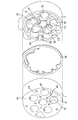
- FIG. 2 is a perspective view showing a front side cylinder block and a rear side cylinder block of the piston compressor according to the present invention.
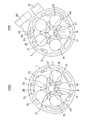
- FIG. 3 is a view of the front-side cylinder block and the rear-side cylinder block of the piston compressor according to the present invention as seen from the crank chamber side.
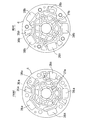
- FIG. 4 is a view of the front head and the rear head of the piston compressor according to the present invention as seen from the cylinder block side.
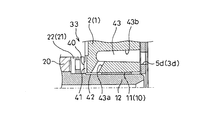
- FIG. 5 is an enlarged sectional view showing the bypass passage.
- FIG. 6 is a view of the bypass passage as viewed from the crank chamber side, (a) is a view as seen from the axial direction of the shaft, and (b) is a perspective view.
- FIG. 1 shows a piston type compressor called a fixed capacity swash plate type reciprocating type used in a refrigeration cycle of a vehicle air conditioner using a refrigerant as a working fluid.
- the compressor is assembled via a valve plate 3 on the front side cylinder block 1, the rear side cylinder block 2 assembled to the front side cylinder block 1, and the front side (left side in the figure) of the front side cylinder block 1.
- the rear head 6 assembled to the rear side (right side in the drawing) of the rear cylinder block 2 via the valve plate 5.
- the front head 4, the front side cylinder block 1, the rear side cylinder block 2, and the rear head 6 are fastened in the axial direction by fastening bolts (not shown) to constitute a housing for the entire compressor.
- the front cylinder block 1 and the rear cylinder block 2 are assembled via a gasket 16, and the cranks defined by assembling the respective cylinder blocks are assembled inside.
- a chamber 7 is formed.
- the crank chamber 7 is rotatably supported by shaft insertion holes 8 and 9 formed in the front side cylinder block 1 and the rear side cylinder block 2 via bearings composed of plain bearings 10 and 11, and one end thereof is a front head.
- a shaft 12 protruding from 4 is disposed.
- the plain bearings 10 and 11 are attached at positions that do not hinder the opening of the side holes of the in-shaft passage described later.
- a seal member 13 for preventing refrigerant leakage is disposed between the front end portion of the shaft 12 and the front head 4, and an electromagnetic clutch 14 is attached to the front end of the shaft 12 protruding from the front head 4. It is supposed to be.
- each cylinder block 1, 2 is parallel to the shaft insertion holes 8, 9, and has a plurality of parts arranged at equal intervals on the circumference around the shaft.
- a cylinder bore 15 is formed.
- a double-headed piston 17 having heads 17b at both ends is inserted into each cylinder bore 15 so as to be reciprocally slidable.
- a compression chamber 18 is interposed between the head 17b of the double-headed piston 17 and the valve plates 3 and 5. Is defined.
- a swash plate 20 that is accommodated in the crank chamber 7 and rotates together with the shaft 12 is formed integrally with the shaft 12.
- the swash plate 20 is rotatably supported via thrust bearings 21 and 22 with respect to the front side cylinder block 1 and the rear side cylinder block 2, and a hemispherical shape provided so that a peripheral portion sandwiches the front and rear.
- a pair of shoes 23a and 23b are moored in a mooring recess 17a formed at the center of the double-headed piston 17. Therefore, when the shaft 12 rotates and the swash plate 20 rotates, the rotational motion is converted into the reciprocating motion of the double-headed piston 17 via the shoes 23a and 23b, and the volume of the compression chamber 18 changes.
- Each of the valve plates 3 and 5 has suction holes 3a and 5a that are opened and closed by a suction valve provided on the cylinder block side end surface, and a discharge hole 3b that is opened and closed by a discharge valve provided on the cylinder head side end surface. 5b is formed corresponding to each cylinder bore.
- the front head 4 and the rear head 6 contain the suction chambers 27 a and 27 b for containing the refrigerant supplied to the compression chamber 18 and the refrigerant discharged from the compression chamber 18.
- the discharge chambers 28a and 28b are respectively formed.
- the suction chambers 27a and 27b are formed at substantially the center of the respective heads 4 and 6, and the discharge chambers 28a and 28b are formed around the suction chambers 27a and 27b.
- the rear cylinder block 2 constituting the housing has a suction port 30 for sucking refrigerant from an external cycle, and a discharge port 31 for discharging compressed refrigerant that communicates with the discharge chambers 28a and 28b. Is formed.
- the suction path from the suction port 30 to the suction chambers 27a and 27b is a first suction that guides the refrigerant flowing from the suction port 30 directly to the suction chambers 27a and 27b without passing through the crank chamber 7. It has a path and a second suction path that leads to the suction chamber via the crank chamber 7 that communicates with the suction port 30. Further, the second suction path further separates oil reaching the respective suction chambers 27a and 27b of the front head 4 and the rear head 6 via a passage in the shaft formed in the shaft 12 penetrating the crank chamber 7.
- the passage 32 and the oil separation passage 32 are provided in parallel, and include a bypass passage 33 that bypasses the shaft 12 from the crank chamber 7 to the suction chambers 27a and 27b through the cylinder block 1.2. ing.
- an axial passage 34 extending in the axial direction connected to the suction port 30 is formed outside the crank chamber 7, and the first suction passage is formed outside the crank chamber 7.
- the axial passage 34 extends to the front head 4 and the rear head 6, and the introduction chamber 35 a formed in the front head 4 and the rear head 6 through the through holes 3 c and 5 c formed in the valve plates 3 and 5,
- the radial passages 36a and 36b are formed in the radial direction so as not to interfere with the discharge chambers 28a and 28b in the front head 4 and the rear head 6, respectively.
- the inlet chambers 35a and 35b and the suction chambers 27a and 27b are connected to each other, and a part of the refrigerant sucked from the suction port 30 is not passed through the crank chamber 7 before the compressor.
- the second suction path is provided with an opening 39 communicating with the crank chamber 7 in the middle of the axial passage 34, and the working fluid is led from the opening 39 to the crank chamber, and then led to the suction chamber.
- the oil separation passage 32 is drilled in the shaft 12 from the rear end to the front side along the axial direction, and the opening end on the rear side opens into a suction chamber 27b provided in the rear head 6;
- the front head 4 communicates with the shaft hole 32a, is provided in the radial direction of the shaft 12 and opens to the crank chamber 7, and communicates with the shaft hole 32a and is provided in the radial direction of the shaft 12.
- an outflow side hole 32c opened in the suction chamber 27a.
- the bypass passage 33 includes thrust bearings 21 and 22 that rotatably support the swash plate 20 and thrust blocks provided in the cylinder blocks 1 and 2 that receive the thrust bearings 21 and 22.
- a groove 41 provided between the bearing receiving surface 40, a space 42 between the shaft 12 and the shaft insertion holes 8 and 9 into which the shaft 12 is inserted, and the cylinder blocks 1 and 2 are formed at one end.
- a block through-hole 43 is formed in the inner wall surface of the holes 8 and 9, and the other end communicates with the suction chambers 27a and 27b through the through-holes 3d and 5d formed in the valve plates 3 and 5, respectively.
- the grooves 41 are formed radially on the thrust bearing receiving surfaces 40 of the cylinder blocks 1 and 2 that are in contact with the thrust traces of the thrust bearings 21 and 22 as shown in FIG.
- the radial grooves 41 are formed by forming from the portion outside the portion where the thrust traces of the thrust bearings 21 and 22 abut to the shaft insertion holes 8 and 9.
- the radial grooves 41 are substantially equally spaced in the circumferential direction.
- the five cylinder bores 15 are formed between adjacent cylinder bores.
- the block through-hole 43 is open on the inner peripheral surface of the shaft insertion holes 8 and 9 on the front side (crank chamber side) with respect to the plain bearings 10 and 11 that rotatably support the shaft 12, and the groove 41
- the working fluid flowing out through the space 42 between the shaft 12 and the shaft insertion holes 8 and 9 bypasses the plain bearings 10 and 11 and is guided to the suction chambers 27a and 27b.
- a plurality of bottomed parallel holes (casting holes) 43b drilled substantially parallel to the shaft center of the shaft 12 from the non-crank chamber side of the cylinder blocks 1 and 2 and the inner periphery of the shaft insertion hole 8
- a block through-hole 43 is formed by an inclined hole 43a formed on the surface at a predetermined angle with respect to the shaft center of the shaft, and a space 42 between the shaft insertion holes 8 and 9 and the shaft 12 is formed via the inclined hole 43a.
- the parallel holes 43b communicate with each other.
- the block through-hole 43 (inclined hole 43a) is opposite to the opening 39 through which the working fluid flows into the crank chamber 7 with respect to the shaft center of the shaft 12 (the shaft as viewed from the opening 39). Two are provided on the side farther from the axis of 12 (see FIG. 6B).
- FIG. 1 for convenience of explanation, the position where the inclined hole 43 a is provided is drawn on the upper side of the shaft 12.
- the opening 39 is located with respect to the axis of the shaft 12. It is possible to guide the working fluid flowing into the crank chamber 7 to a part of the plurality of grooves 41 constituting the bypass passage 33 without being biased.
- the distribution ratio of the working fluid flowing in from the suction port 30 is set as follows, for example.
- the flow rate directly led from the suction port 30 to the suction chambers 27a and 27b without passing through the crank chamber 7 is about 35% of the total suction amount for each of the front side and the rear side, and diverted to the crank chamber 7 Is set to be about 30% of the total inhalation amount.
- the first suction path that leads directly from the suction port 30 to the front or rear suction chambers 27a, 27b is set so that the minimum path cross section of the path is equivalent to about ⁇ 12 hole (equivalent to a circle having a diameter of about 12 mm). Therefore, the pressure loss is formed to a level acceptable for performance.
- the flow rate that has flowed into the crank chamber 7 the flow rate that is guided to the suction chambers 27 a and 27 b via the oil separation passage 32 (the inflow side hole 32 b, the shaft hole 32 a, and the outflow side hole 32 c of the shaft 12).
- the flow rate led to the suction chambers 27a and 27b through the bypass passage 33 is set to about 60% (about 18% of the total suction flow rate).
- the first suction path led directly from the suction port 30 to the suction chambers 27a and 27b is provided to reduce the flow rate flowing into the crank chamber 7, but from the crank chamber 7 to the suction chamber.
- the second suction path that guides the working fluid to 27a and 27b is configured by providing the bypass passage 33 and the oil separation passage 32 in parallel, so that the second suction path passes through the shaft 12 and the suction chamber 27a. , 27b, it is possible to relatively increase the amount of working fluid flowing into the crank chamber as compared with the conventional configuration in which only the oil separation passage is provided.
- the working fluid led to the crank chamber is divided into a bypass passage and an oil separation passage and led to the suction chamber, the inflow side formed in the shaft 12 even if the amount of the working fluid led to the crank chamber increases. It becomes possible to suppress the amount of working fluid (flow velocity of working fluid) passing through the side hole 32b.
- the amount of working fluid flowing into the crank chamber can be increased to ensure cooling of the crank chamber, and a part of the working fluid introduced into the crank chamber can be transferred to the suction chamber via the bypass passage 33. Therefore, the flow rate of the working fluid flowing into the inflow side hole 32b of the shaft 12 is suppressed, and the oil-mixed refrigerant in the crank chamber 7 is separated from the oil by the centrifugal separation action by the rotation of the shaft 12, Oil can be left in the crank chamber.
- the groove 41 constituting the bypass passage 33 has the thrust bearings provided on the thrust bearings 21 and 22 that rotatably support the swash plate 20 and the cylinder blocks 1 and 2 that receive the thrust bearings. 40, the thrust bearings 21 and 22 can be preferentially cooled, wear in the vicinity of the thrust bearing can be reduced, and wear powder generated by wear of the thrust bearing can be reduced. Can be discharged from the crank chamber through the bypass passage.
- bypass passage 33 is provided so as to bypass the plain bearings 10 and 11, the wear powder in the working fluid flowing through the bypass passage 33 is not guided to the plain bearing, and the shaft 12 can be smoothly smoothed.
- the bypass passage 33 is formed in the groove 41, the space between the shaft 12 and the shaft insertion holes 8 and 9 into which the shaft 12 is inserted, and the shaft insertion holes 8 and 8. 9 is formed by the block through-holes 43 formed in the cylinder blocks 1 and 2 so as to open to the inner peripheral surface of the cylinder 9, and flows into the suction chamber from the crank chamber 7 via the bypass passage 33. Oil outflow can also be suppressed.
Landscapes
- Engineering & Computer Science (AREA)
- Mechanical Engineering (AREA)
- General Engineering & Computer Science (AREA)
- Compressor (AREA)
- Compressors, Vaccum Pumps And Other Relevant Systems (AREA)
Abstract
Description
これにより、シャフトの側孔から吸い込まれる作動流体の流速が遅くなり、十分なオイル分離機能が得られるようになっている。
また、クランク室内の摺動部位で摩耗が発生した場合の摩耗粉の除去を図り、摺動部品に摩耗粉が付着することによる悪影響を抑えることをも課題としている。
このため、クランク室内の冷却を確保しつつ、シャフトの回転による遠心分離機能が維持されて、クランク室にオイルを残留させることが可能となる。
このような構成においては、バイパス通路を入り組んだ構造にすることで、上述した作用効果に加えて、クランク室からのオイルの流出の懸念を回避することも可能となる。
このため、クランク室内の摺動部品の信頼性を確保することができ、また、クランク室から吸い出されるオイルを低減することが可能となる。
2 リア側シリンダブロック
4 フロントヘッド
6 リアヘッド
7 クランク室
8,9 シャフト挿入孔
10,11 プレーンベアリング
12 シャフト
15 シリンダボア
17 ピストン
20 斜板
21,22 スラスト軸受
27a,27b 吸入室
28a,28b 吐出室
30 吸入口
31 吐出口
32 オイル分離通路
32a 軸孔
32b 流入側側孔
32c 流出側側孔
33 バイパス通路
40 スラスト軸受受面
41 溝
42 空間
43 ブロック貫通孔
この斜板20は、フロント側シリンダブロック1及びリア側シリンダブロック2に対してスラスト軸受21,22を介して回転自在に支持されており、周縁部分が前後を挟み込むように設けられた半球状の一対のシュー23a,23bを介して両頭ピストン17の中央部に形成された係留凹部17aに係留されている。したがって、シャフト12が回転して斜板20が回転すると、その回転運動がシュー23a,23bを介して両頭ピストン17の往復運動に変換され、圧縮室18の容積が変化するようになっている。
この例では、シリンダブロック1,2の反クランク室側からシャフト12の軸心と略平行に穿設された複数の有底の平行穴(鋳抜き孔)43bと、シャフト挿入孔8の内周面にシャフトの軸心に対して所定の角度で穿設された傾斜孔43aとによってブロック貫通孔43を構成し、シャフト挿入孔8,9とシャフト12の間の空間42を傾斜孔43aを介して平行穴43bに連通させるようにしている。
先ず、吸入口30からクランク室7を経由せずに直接吸入室27a,27bへ導く流量を、フロント側、リア側のそれぞれについて全体の吸入量の約35%づつとし、クランク室7へ導く流用を全体の吸入量の約30%とするように通路断面を設定する。この例においては、吸入口30からフロント側又はリア側の吸入室27a,27bへ直接導く第1の吸入経路は、経路の最小通路断面が約φ12孔相当(直径約12mmの円相当)に設定されており、圧力損失が性能上許容できるレベルに大きく形成されている。
また、クランク室7に流入された流量のうち、オイル分離通路32(シャフト12の流入側側孔32b、軸孔32a、流出側側孔32c)を介して吸入室27a,27bに導かれる流量を約40%(全体の吸入流量の約12%)とし、バイパス通路33を介して吸入室27a,27bに導かれる流量を約60%(全体の吸入流量の約18%)としている。
Claims (5)
- クランク室に臨むシリンダボアが形成された少なくとも1つのシリンダブロックと、シリンダボア内を往復摺動するピストンと、吸入室及び吐出室が形成されてバルブプレートを介して前記シリンダブロックに接合される少なくとも1つのシリンダヘッドと、前記クランク室を貫通し、前記シリンダブロックに回転自在に支承されたシャフトと、前記クランク室に収容され、前記シャフトの回転により回転して前記ピストンを往復動させる斜板と、前記シリンダブロック又は前記シリンダヘッドに形成されて作動流体を吸入する吸入口及び吐出する吐出口とを有し、前記吸入口から吸入した作動流体を前記吸入室へ導き、前記ピストンにより圧縮した後に前記吐出室を介して前記吐出口から吐出させるピストン型圧縮機であって、
前記シャフトに、軸方向に沿って設けられた軸孔と、この軸孔に連通し、前記シャフトの径方向に設けられて前記クランク室に開口する側孔とを少なくとも形成し、
前記吸入口から流入された作動流体を前記クランク室を経由せずに前記吸入室へ直接導く第1の吸入経路と、
前記吸入口から流入された作動流体を前記クランク室を経由して前記吸入室へ導く第2の吸入経路とを有し、
前記第2の吸入経路は、前記クランク室から前記シャフトに形成された前記側孔及び前記軸孔を介して前記吸入室に導かれるオイル分離通路と、前記クランク室から前記シャフト内を経由せずに前記シリンダブロックを通して前記吸入室へ導かれるバイパス通路とを具備する
ことを特徴とするピストン型圧縮機。 - 前記バイパス通路は、前記斜板を回転支持するスラスト軸受とこのスラスト軸受を受ける前記シリンダブロックに設けられたスラスト軸受受面との間に設けられた溝を有して構成されることを特徴とする請求項1記載のピストン型圧縮機。
- 前記バイパス通路は、前記斜板を回転支持するスラスト軸受と前記シリンダブロックに設けられた前記スラスト軸受受け面との間に設けられた溝と、この溝に連通し、前記シャフトとこのシャフトを挿入するシャフト挿入孔との間の空間、及び前記シャフト挿入孔の内周面に開口するよう前記シリンダブロックに形成された通孔とにより構成されることを特徴とする請求項2記載のピストン型圧縮機。
- 前記シャフトは、前記ハウジングに対してプレーンベアリングを介して回転自在に支承され、
前記バイパス通路は、前記プレーンベアリングを迂回するように前記シリンダブロックに設けられていることを特徴とする請求項1乃至3のいずれかに記載のピストン型圧縮機。 - 前記通孔は、前記シャフトの軸心に対して前記作動流体が前記クランク室に流入される部位とは反対側に少なくとも1つ設けられていることを特徴とする請求項3記載のピストン型圧縮機。
Priority Applications (4)
| Application Number | Priority Date | Filing Date | Title |
|---|---|---|---|
| KR1020127025376A KR20130030743A (ko) | 2010-03-31 | 2010-03-31 | 피스톤형 압축기 |
| PCT/JP2010/002388 WO2011121669A1 (ja) | 2010-03-31 | 2010-03-31 | ピストン型圧縮機 |
| US13/638,146 US9169835B2 (en) | 2010-03-31 | 2010-03-31 | Piston-type compressor |
| CN201080065487.1A CN102803727B (zh) | 2010-03-31 | 2010-03-31 | 活塞式压缩机 |
Applications Claiming Priority (1)
| Application Number | Priority Date | Filing Date | Title |
|---|---|---|---|
| PCT/JP2010/002388 WO2011121669A1 (ja) | 2010-03-31 | 2010-03-31 | ピストン型圧縮機 |
Publications (1)
| Publication Number | Publication Date |
|---|---|
| WO2011121669A1 true WO2011121669A1 (ja) | 2011-10-06 |
Family
ID=44711466
Family Applications (1)
| Application Number | Title | Priority Date | Filing Date |
|---|---|---|---|
| PCT/JP2010/002388 Ceased WO2011121669A1 (ja) | 2010-03-31 | 2010-03-31 | ピストン型圧縮機 |
Country Status (4)
| Country | Link |
|---|---|
| US (1) | US9169835B2 (ja) |
| KR (1) | KR20130030743A (ja) |
| CN (1) | CN102803727B (ja) |
| WO (1) | WO2011121669A1 (ja) |
Families Citing this family (8)
| Publication number | Priority date | Publication date | Assignee | Title |
|---|---|---|---|---|
| JP5741554B2 (ja) | 2012-11-02 | 2015-07-01 | 株式会社豊田自動織機 | ピストン型圧縮機 |
| JP6242606B2 (ja) * | 2013-06-27 | 2017-12-06 | 株式会社ヴァレオジャパン | ベーン型圧縮機 |
| CN103742403A (zh) * | 2014-01-14 | 2014-04-23 | 无锡双鸟科技股份有限公司 | 一种汽车空调压缩机 |
| SG11201708710YA (en) * | 2015-05-13 | 2017-11-29 | Carrier Corp | Economized reciprocating compressor |
| JP6477441B2 (ja) * | 2015-11-20 | 2019-03-06 | 株式会社豊田自動織機 | 可変容量型斜板式圧縮機 |
| CN106949034A (zh) * | 2017-04-12 | 2017-07-14 | 合肥达因汽车空调有限公司 | 一种低油耗、低噪音的旋转斜盘式压缩机 |
| CN111373147B (zh) * | 2017-12-26 | 2022-02-11 | 株式会社前川制作所 | 往复运动式压缩机 |
| US11773837B1 (en) * | 2022-06-03 | 2023-10-03 | T/CCI Manufacturing, L.L.C. | Compressor |
Citations (3)
| Publication number | Priority date | Publication date | Assignee | Title |
|---|---|---|---|---|
| JPH07317655A (ja) * | 1994-05-23 | 1995-12-05 | Sanden Corp | 斜板式圧縮機 |
| JPH08144947A (ja) * | 1994-11-25 | 1996-06-04 | Toyota Autom Loom Works Ltd | 斜板式圧縮機 |
| JP2009108750A (ja) * | 2007-10-30 | 2009-05-21 | Valeo Thermal Systems Japan Corp | ピストン型圧縮機 |
Family Cites Families (13)
| Publication number | Priority date | Publication date | Assignee | Title |
|---|---|---|---|---|
| US4070136A (en) * | 1973-05-11 | 1978-01-24 | Kabushiki Kaisha Toyoda Jidoshokki Seisakusho | Apparatus for lubricating a swash plate compressor |
| US4229145A (en) * | 1977-01-27 | 1980-10-21 | Diesel Kiki Co., Ltd. | Swash plate compressor |
| DE2922307A1 (de) * | 1978-06-02 | 1979-12-06 | Hitachi Ltd | Taumelscheiben-verdichter |
| JPS5732084A (en) * | 1980-07-31 | 1982-02-20 | Diesel Kiki Co Ltd | Swash plate type compressor |
| US5044892A (en) * | 1990-03-05 | 1991-09-03 | General Motors Corporation | Swash plate compressor lubrication system |
| JP3277081B2 (ja) | 1994-10-13 | 2002-04-22 | 株式会社東芝 | 異形樹脂粒子、樹脂粒子の異形化方法、及び異形樹脂粒子からなる電子写真用トナー |
| KR0167631B1 (ko) * | 1994-11-25 | 1999-03-20 | 이소가이 찌세이 | 사판식 압축기 |
| JP4003673B2 (ja) * | 2003-03-13 | 2007-11-07 | 株式会社豊田自動織機 | ピストン式圧縮機 |
| JP4946340B2 (ja) * | 2005-10-17 | 2012-06-06 | 株式会社豊田自動織機 | 両頭ピストン式圧縮機 |
| JP2008025476A (ja) | 2006-07-21 | 2008-02-07 | Valeo Thermal Systems Japan Corp | 圧縮機 |
| KR101159863B1 (ko) * | 2006-07-24 | 2012-06-25 | 한라공조주식회사 | 압축기 |
| US8118566B2 (en) * | 2006-11-09 | 2012-02-21 | Valeo Thermal Systems Japan Corporation | Piston compressor with second intake |
| JP5229667B2 (ja) | 2009-03-24 | 2013-07-03 | 株式会社ヴァレオジャパン | ピストン型圧縮機 |
-
2010
- 2010-03-31 US US13/638,146 patent/US9169835B2/en active Active
- 2010-03-31 WO PCT/JP2010/002388 patent/WO2011121669A1/ja not_active Ceased
- 2010-03-31 KR KR1020127025376A patent/KR20130030743A/ko not_active Ceased
- 2010-03-31 CN CN201080065487.1A patent/CN102803727B/zh active Active
Patent Citations (3)
| Publication number | Priority date | Publication date | Assignee | Title |
|---|---|---|---|---|
| JPH07317655A (ja) * | 1994-05-23 | 1995-12-05 | Sanden Corp | 斜板式圧縮機 |
| JPH08144947A (ja) * | 1994-11-25 | 1996-06-04 | Toyota Autom Loom Works Ltd | 斜板式圧縮機 |
| JP2009108750A (ja) * | 2007-10-30 | 2009-05-21 | Valeo Thermal Systems Japan Corp | ピストン型圧縮機 |
Also Published As
| Publication number | Publication date |
|---|---|
| US20130042750A1 (en) | 2013-02-21 |
| US9169835B2 (en) | 2015-10-27 |
| KR20130030743A (ko) | 2013-03-27 |
| CN102803727A (zh) | 2012-11-28 |
| CN102803727B (zh) | 2016-01-20 |
Similar Documents
| Publication | Publication Date | Title |
|---|---|---|
| WO2011121669A1 (ja) | ピストン型圧縮機 | |
| KR100840915B1 (ko) | 사판식 압축기 | |
| JP3855940B2 (ja) | 圧縮機における潤滑構造 | |
| US8562309B2 (en) | Piston compressor | |
| JP2006307700A (ja) | 圧縮機 | |
| JP3855949B2 (ja) | 両頭ピストン式圧縮機 | |
| JP5229667B2 (ja) | ピストン型圧縮機 | |
| JP5846012B2 (ja) | 斜板式圧縮機 | |
| JP4513684B2 (ja) | 両頭ピストン式圧縮機 | |
| KR101386381B1 (ko) | 피스톤형 압축기 | |
| US8419382B2 (en) | Piston compressor | |
| JP2010013987A (ja) | ピストン式圧縮機における冷媒吸入構造 | |
| JP2009108750A (ja) | ピストン型圧縮機 | |
| KR101730833B1 (ko) | 압축기 | |
| JP4043233B2 (ja) | 気体圧縮機 | |
| JP5146807B2 (ja) | 斜板式圧縮機の潤滑構造及び斜板式圧縮機 | |
| WO2018207724A1 (ja) | 圧縮機 | |
| KR20080107612A (ko) | 압축기 | |
| JPH10196530A (ja) | 斜板式圧縮機におけるシャフトシール機構の潤滑構造 | |
| JPH10196529A (ja) | 往復動型圧縮機 | |
| KR101099110B1 (ko) | 왕복동식 압축기 | |
| JP2010133308A (ja) | 両頭ピストン式圧縮機 | |
| KR20080107611A (ko) | 압축기 | |
| JP2009103073A (ja) | 斜板式圧縮機 | |
| JP2009002203A (ja) | ピストン式圧縮機 |
Legal Events
| Date | Code | Title | Description |
|---|---|---|---|
| WWE | Wipo information: entry into national phase |
Ref document number: 201080065487.1 Country of ref document: CN |
|
| 121 | Ep: the epo has been informed by wipo that ep was designated in this application |
Ref document number: 10848851 Country of ref document: EP Kind code of ref document: A1 |
|
| ENP | Entry into the national phase |
Ref document number: 20127025376 Country of ref document: KR Kind code of ref document: A |
|
| WWE | Wipo information: entry into national phase |
Ref document number: 2283/MUMNP/2012 Country of ref document: IN |
|
| WWE | Wipo information: entry into national phase |
Ref document number: 1201005014 Country of ref document: TH |
|
| NENP | Non-entry into the national phase |
Ref country code: DE |
|
| WWE | Wipo information: entry into national phase |
Ref document number: 13638146 Country of ref document: US |
|
| 122 | Ep: pct application non-entry in european phase |
Ref document number: 10848851 Country of ref document: EP Kind code of ref document: A1 |
|
| NENP | Non-entry into the national phase |
Ref country code: JP |