WO2011114994A1 - プログラマブルコントローラ - Google Patents
プログラマブルコントローラ Download PDFInfo
- Publication number
- WO2011114994A1 WO2011114994A1 PCT/JP2011/055679 JP2011055679W WO2011114994A1 WO 2011114994 A1 WO2011114994 A1 WO 2011114994A1 JP 2011055679 W JP2011055679 W JP 2011055679W WO 2011114994 A1 WO2011114994 A1 WO 2011114994A1
- Authority
- WO
- WIPO (PCT)
- Prior art keywords
- transmission
- unit
- frame
- slave
- transmitted
- Prior art date
Links
Images


Classifications
-
- G—PHYSICS
- G05—CONTROLLING; REGULATING
- G05B—CONTROL OR REGULATING SYSTEMS IN GENERAL; FUNCTIONAL ELEMENTS OF SUCH SYSTEMS; MONITORING OR TESTING ARRANGEMENTS FOR SUCH SYSTEMS OR ELEMENTS
- G05B19/00—Programme-control systems
- G05B19/02—Programme-control systems electric
- G05B19/04—Programme control other than numerical control, i.e. in sequence controllers or logic controllers
- G05B19/05—Programmable logic controllers, e.g. simulating logic interconnections of signals according to ladder diagrams or function charts
- G05B19/054—Input/output
-
- H—ELECTRICITY
- H04—ELECTRIC COMMUNICATION TECHNIQUE
- H04L—TRANSMISSION OF DIGITAL INFORMATION, e.g. TELEGRAPHIC COMMUNICATION
- H04L12/00—Data switching networks
- H04L12/28—Data switching networks characterised by path configuration, e.g. LAN [Local Area Networks] or WAN [Wide Area Networks]
- H04L12/40—Bus networks
- H04L12/40006—Architecture of a communication node
- H04L12/40013—Details regarding a bus controller
-
- H—ELECTRICITY
- H04—ELECTRIC COMMUNICATION TECHNIQUE
- H04L—TRANSMISSION OF DIGITAL INFORMATION, e.g. TELEGRAPHIC COMMUNICATION
- H04L12/00—Data switching networks
- H04L12/28—Data switching networks characterised by path configuration, e.g. LAN [Local Area Networks] or WAN [Wide Area Networks]
- H04L12/40—Bus networks
- H04L12/403—Bus networks with centralised control, e.g. polling
- H04L12/4035—Bus networks with centralised control, e.g. polling in which slots of a TDMA packet structure are assigned based on a contention resolution carried out at a master unit
-
- G—PHYSICS
- G05—CONTROLLING; REGULATING
- G05B—CONTROL OR REGULATING SYSTEMS IN GENERAL; FUNCTIONAL ELEMENTS OF SUCH SYSTEMS; MONITORING OR TESTING ARRANGEMENTS FOR SUCH SYSTEMS OR ELEMENTS
- G05B2219/00—Program-control systems
- G05B2219/10—Plc systems
- G05B2219/11—Plc I-O input output
- G05B2219/1129—Serial addressed modules on bus
-
- G—PHYSICS
- G05—CONTROLLING; REGULATING
- G05B—CONTROL OR REGULATING SYSTEMS IN GENERAL; FUNCTIONAL ELEMENTS OF SUCH SYSTEMS; MONITORING OR TESTING ARRANGEMENTS FOR SUCH SYSTEMS OR ELEMENTS
- G05B2219/00—Program-control systems
- G05B2219/10—Plc systems
- G05B2219/12—Plc mp multi processor system
- G05B2219/1215—Master slave system
-
- H—ELECTRICITY
- H04—ELECTRIC COMMUNICATION TECHNIQUE
- H04L—TRANSMISSION OF DIGITAL INFORMATION, e.g. TELEGRAPHIC COMMUNICATION
- H04L1/00—Arrangements for detecting or preventing errors in the information received
- H04L1/12—Arrangements for detecting or preventing errors in the information received by using return channel
- H04L1/16—Arrangements for detecting or preventing errors in the information received by using return channel in which the return channel carries supervisory signals, e.g. repetition request signals
- H04L1/18—Automatic repetition systems, e.g. Van Duuren systems
- H04L1/1829—Arrangements specially adapted for the receiver end
- H04L1/1858—Transmission or retransmission of more than one copy of acknowledgement message
-
- H—ELECTRICITY
- H04—ELECTRIC COMMUNICATION TECHNIQUE
- H04L—TRANSMISSION OF DIGITAL INFORMATION, e.g. TELEGRAPHIC COMMUNICATION
- H04L1/00—Arrangements for detecting or preventing errors in the information received
- H04L1/12—Arrangements for detecting or preventing errors in the information received by using return channel
- H04L1/16—Arrangements for detecting or preventing errors in the information received by using return channel in which the return channel carries supervisory signals, e.g. repetition request signals
- H04L1/18—Automatic repetition systems, e.g. Van Duuren systems
- H04L1/1867—Arrangements specially adapted for the transmitter end
- H04L1/189—Transmission or retransmission of more than one copy of a message
Definitions
- the present invention relates to a programmable controller, and more particularly to an improvement in a transmission method between units using a system bus.
- the network system in FA is operated by one or more PLCs (Programmable Logic Controllers) that control the input and output devices of industrial robots and other production equipment deployed in the production factory.
- PLCs Process Control Circuits
- the device to be controlled is connected to a control system network.
- the PLC is configured by connecting various units such as a CPU unit and an I / O unit. Connect input devices such as sensors and switches to the I / O unit and connect output devices such as actuators and relays that capture their on / off signals as input signals and output signals to them. There are output units to send out. Based on the output data written in the memory of the output unit by the MPU of the CPU unit, the output unit outputs an output signal to the output device. An input signal input from the input device is stored in a memory in the input unit, and the MPU of the CPU unit accesses the memory to acquire input data. As described above, the MPU of the CPU unit accesses the memory of each unit to read / write data. However, as the processing speed increases, it has become difficult for the MPU to access the memory of each unit to read / write data.
- the present inventor considered using a communication technology between nodes connected to the PLC network cable to perform data transmission / reception between units constituting one PLC. Specifically, data is transmitted and received by master-slave communication with the CPU unit as a master and the other units as slaves. Also, this type of communication technology takes a mechanism in which an ACK frame is returned from the other party when the transmission frame is normally received by the other party, and if the master does not return an ACK frame within a certain period of time, Therefore, it is determined that the transmission could not be performed and the retransmission is performed. Thereby, the target data can be reliably transmitted to the other party. This type of retransmission technique is disclosed in Patent Document 1 and the like.
- the retransmission technique performed between nodes connected to a general network cannot be directly used for data communication between PLC units. That is, data transmission / reception between units constituting the PLC is required to send data one after another at a high speed. However, once the transmission frame storing the data is sent, the presence or absence of an ACK frame from the other party is confirmed, retransmitted if not delivered, and the transmission frame storing the next data is transmitted when transmission is complete The waiting time becomes longer, and the significance of transmitting and receiving data at high speed using communication technology is lost.
- the programmable controller of the present invention is (1) a programmable controller configured by connecting one master unit and a plurality of slave units to a system bus, and the master unit is different. Added a function to transmit multiple frames sent to the slave unit continuously in a batch.
- the master unit of the present invention continuously transmits a plurality of transmission frames addressed to different slave units a plurality of times. That is, in the first transmission process, the batch transmission frames are transmitted in a predetermined order. Next, in a second transmission process, the batch transmission frames are transmitted in a predetermined order. Thereafter, the transmission process is repeated for a set number of times.
- the order of transmission in the first time and the second time is the same in the embodiment, but is not necessarily the same in the present invention. However, the same method is preferable because the processing (control) can be easily performed. Since the slave unit is a unit constituting the PLC, the slave unit is very close to the master unit and has a short transmission frame propagation time.
- the slave unit has a function of returning a response set when the transmission frame is normally received, and the master unit is applicable even if the response is received less than the plurality of times. It is preferable to stop transmission of transmission frames.
- the set response includes, for example, transmission of an ACK frame or transmission of an IN frame in response to a transmission request frame in the embodiment.
- the response is returned quickly like a slave unit close to the master unit, there is a possibility that the response is returned before sending a plurality of transmission frames.
- the transmission frame has arrived correctly at the other party, and it is useless to send it thereafter. Therefore, since the corresponding transmission frame is not transmitted after the response is received, only a necessary transmission frame can be transmitted, and a load related to communication of the system is reduced.
- the master unit may discard the second and subsequent times.
- the returned response executes a predetermined reception process and is stored in a memory or the like. If a response to the same transmission frame can be received once, it can be confirmed that the transmission frame has been correctly transmitted to the other party. Therefore, subsequent response reception processing is useless and unnecessary memory is wasted. Therefore, in the present invention, it is possible to suppress performing unnecessary processing by discarding the second and subsequent responses.
- the number of times of continuous transmission multiple times is set in the transmission frame addressed to the slave unit constituting the extension block body more than the transmission frame addressed to the slave unit constituting the block body. Good. If there is an extension cable, the effect of noise differs before and after that. That is, when viewed from the master unit, the transmission frame for the slave unit downstream of the extension cable is more susceptible to noise than the transmission frame for the upstream slave unit, and the probability of normal transmission is high.
- the number of continuous transmissions may be the same for all of the batch transmission frames. This is preferable because the number of transmissions can be managed and controlled in a lump. (6) Further, the number of times of continuous transmission a plurality of times may be different in the batch transmission frame. By setting the appropriate number of transmissions for each slave unit in such a configuration, transmission processing can be performed more reliably and without waste.
- the transmission frame is continuously transmitted a plurality of times, communication between the units constituting the PLC can be performed reliably and at high speed.
- FIG. 1 shows a first embodiment of a programmable controller (hereinafter “PLC”) 10 of the present invention.
- the PLC 10 is configured by connecting a plurality of units for realizing various functions.
- the plurality of units have at least one CPU unit 20.
- the PLC 10 of the present embodiment includes an I / O unit 30 (input unit, output unit, input / output unit, etc.), a high function I / O unit 40 (high function input unit, high function output unit, high function input / output unit). Etc.), and an end unit 50 is provided.
- a power supply unit for supplying power to each unit constituting the PLC 10 is also provided.
- the units constituting the PLC 10 are not limited to those described above, and are configured by appropriately selecting necessary units according to the control to be executed.
- Each of these units has a connector 15 on the side of the case.
- Each unit is electrically connected by connecting the connectors 15 together. That is, one end of the high-speed serial communication line is connected to the connector 15, and the other end of the high-speed serial communication line is connected to an internal circuit (ASIC in this embodiment) of the unit. A power line is also connected.
- ASIC internal circuit
- the system bus composed of the high-speed serial communication line of the present embodiment is composed of two systems, a downlink system bus 11 and an uplink system bus 12. In this way, by fixing the direction of the frames flowing through the system buses 11 and 12, the probability of frame collision during communication is suppressed, so that more reliable and smooth transmission is possible.
- the CPU unit 20 controls the operation of each device constituting the FA network, and includes “common processing”, “IN refresh” (processing in which the master reads slave data), “user program calculation execution”, “OUT “Refresh” (processing to write data from master to slave) and “peripheral service” are executed cyclically.
- the CPU unit 20 becomes a master and manages communication with each unit (slave) connected by the system buses 11 and 12.
- the CPU unit 20 includes an MPU 21, an EEPROM 22, a RAM 23, an ASIC 24, and a communication circuit 25.
- the EEPROM 22 stores a system program for the CPU unit, a user program, and IO data such as IN data / OUT data.
- the MPU 21 is a microprocessor unit for the CPU unit, and controls the entire PLC by executing a system program and a user program stored in the EEPROM 22.
- the RAM 23 is a memory used as a work memory when the MPU 21 operates.
- the AISC 24 has a function of executing a part of the user program.
- the ASIC 24 has a function of performing master-slave communication with other units. That is, the ASIC 24 performs master-slave communication with an MPU interface unit (not shown) for communicating with the MPU 21, a shared memory unit 24c for storing IO data transmitted and received with the slave unit, and a slave unit.
- a communication controller unit 24d for managing the data, a transmission control unit 24a connected to the system buses 11 and 12, and a data transmission / reception unit 24b and a reception control unit 24b.
- the transmission control unit 24 a is connected to the downlink system bus 11, and the reception control unit 24 b is connected to the uplink system bus 12.
- the communication circuit 25 communicates with a device such as a remote I / O connected to the field network.
- the I / O unit 30 and the high-function I / O unit 40 connect input devices such as sensors and switches and connect output devices such as actuators and relays that take their on / off signals as input signals. An output unit for sending output signals to them. These units 30 and 40 become slave units.
- the I / O unit 30 includes an ASIC 31 and an interface (not shown) for transmitting / receiving input signals and output signals to / from external devices connected to the I / O unit 30.
- the ASIC 31 is daisy chain connected to the system buses 11 and 12. Therefore, the ASIC 31 includes a transmission control unit 31a and a reception control unit 31b connected to the down system bus 11, a transmission control unit 31c and a reception control unit 31d connected to the up system bus 12, a communication controller unit 31e, and the like.
- the communication controller 31e of the ASIC 31 receives a frame transmitted through the downlink system bus 11 by the reception controller 31b, the communication controller 31e executes a predetermined process and transmits it from the paired transmission controller 31a to the downstream slave unit. To do.
- the reception control unit 31d receives a frame transmitted through the upstream system bus 12
- the communication controller unit 31e executes a predetermined process and transfers from the paired transmission control unit 31c to the upstream adjacent unit.
- Send
- the frame sent by the downlink system bus 11 is addressed to itself and a response / ACK is returned to the CPU unit 20 as the processing result, the response is sent from the transmission control unit 31c to the uplink system bus 12.
- the high function I / O unit 40 includes an ASIC 41, an MPU 44 in addition to an interface (not shown) for transmitting / receiving input signals and output signals to / from external devices connected to the high function I / O unit 40.
- the MPU 44 executes more complicated processing
- the high function I / O unit 40 cyclically executes a series of processing such as arithmetic processing, IO refresh, common processing, and peripheral services. That is, the high function I / O unit 40 has a function of controlling the operation of the output device connected to itself, and can also be called a special unit.
- the arithmetic processing may be executed by executing a preset program or by executing a user program.
- the ASIC 41 of the high function I / O unit 40 is connected to the system buses 11 and 12 by a daisy chain. Therefore, the ASIC 41 includes a transmission control unit 41a and a reception control unit 41b connected to the downlink system bus 11, a transmission control unit 41c and a reception control unit 41d connected to the uplink system bus 12, a communication controller unit 41e, and the like. . Further, since the high function I / O unit 40 includes the MPU 44, the ASIC 41 includes the MPU interface unit. Furthermore, in the present embodiment, since the high function I / O unit 40 is the last unit farthest from the CPU unit 20, the end unit 50 is mounted after that. The transmission control unit 41 a of the ASIC 41 of the high function I / O unit 40 is connected to the termination resistor 51 in the end unit 50.
- the ASIC 24 of the CPU unit 20 that is the master creates and transmits various frames.
- the frame to be transmitted is generated by, for example, an OUT frame for transmitting OUT data, a transmission request frame for requesting IN data to the slave, a transmission request frame for requesting transmission of message data to the slave, or an application.
- These transmission frames store, for example, data to be transmitted by the MPU 21 in a transmission table in the shared memory unit 24c of the ASIC 24.
- the communication controller unit 24d reads out the data, gives it to the transmission control unit 24a, encodes it by adding a header and a correction code, performs parallel / serial conversion, and transmits it to the downstream system bus 11. Send.
- a unique transaction ID is added to each frame for each transmission request in the transmission frame.
- the slave units such as the I / O unit 30 and the high-function I / O unit 40 receive the transmission frame by the reception control units 31b and 41b, the slave unit performs serial / parallel conversion and then performs decoding and frame check. If it is determined that the check is normal, in the case of a transmission frame addressed to itself, a predetermined process based on the data transmitted in the transmission frame is executed.
- the slave unit performs OUT refresh based on the transmitted OUT data, creates an ACK frame, and transmits it from the transmission control units 31c and 41c to the master unit.
- the ASIC 24 of the CPU unit 20 acquires this ACK frame via the reception control unit 24b, it recognizes that the previously transmitted OUT frame has been received. If the transmission frame is a transmission request frame for requesting IN data, the slave unit creates an IN frame storing the latest IN data, and returns it to the master from the transmission control units 31c and 41c.
- the slave unit When the transmission frame is a transmission request frame for requesting message data, the slave unit creates a message frame storing the message when there is a message that can be transmitted at the time of reception, and sends the message from the transmission control units 31c and 41c to the master. Return it. Furthermore, when the transmission frame is an interrupt frame, the ASIC of the slave unit performs processing according to the interrupt request, creates an ACK frame, and transmits the ACK frame from the transmission control units 31c and 41c to the master unit. The transaction ID added to the transmission frame is added to the ACK frame. Thus, the CPU unit 20 can recognize which transmission request the received ACK frame is for, using the transaction ID as a key.
- the transmission frame received by the reception control unit 24b is given to the communication controller units 31e and 41e, and finally is subjected to parallel-serial conversion and transmission by the transmission control units 31a and 41a. It is output to the down system bus 11 that is a road.
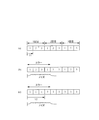
- the ASIC 24 of the CPU unit 20 that is the master unit waits for reception of an ACK frame from the slave unit for a plurality of batch transmission requests set in the transmission table in the shared memory unit 24c. Instead, it transmits continuously in a predetermined order for a specified number of times. That is, for example, if there are three transmission requests and the number of repeated transmissions is three, the ASIC 24 executes transmission processing at the timings shown in FIGS. In FIG. 2, for the sake of convenience of illustration, the transmission frames of the respective transmission requests are shown only with numbers. Also, each transmission frame is sent one after another in a packed state. Thereby, high-speed transmission on the system bus is ensured, and high-speed communication between the units constituting the PLC 10 is ensured.
- the ASIC 24 creates and transmits transmission frames for each transmission request in the order of transmission request-1, transmission request-2, and transmission request-3. Then, if the ASIC 24 has transmitted the transmission frame of the last transmission request-3 of the group, the ASIC 24 proceeds to the second transmission process, and in the order of transmission request-1, transmission request-2, transmission request-3, A transmission frame for a transmission request is created and transmitted. Thereafter, the process proceeds to the third transmission process, and the ASIC 24 transmits in order from transmission request-1.
- the ASIC 24 transmits the transmission frame of transmission request-3
- the ASIC 24 starts a timer for monitoring the ACK check time.
- the ACK monitoring timer may be started every time transmission is generally performed.
- the ASIC 24 can recognize which transmission request it is based on the transaction ID included in the ACK frame.
- the received ACK frame is stored in a predetermined memory area of the shared memory unit 24c. Then, the ASIC 24 determines whether or not ACK frames (or responses from slave units such as IN frames) for all transmission request frames that require ACK have been returned when the ACK check time has elapsed in the timer. If the delivery confirmation for all the transmission frames belonging to the transmission request group is completed, the processing is normally completed.
- the type of transmission frame there are some that only transmit and do not request a response from the slave unit. For such transmission frames, it is considered that there is an ACK frame or excluded from the monitoring target. .
- the MPU 21 and / or the ASIC 24 of the CPU unit 20 execute a predetermined process.
- the ACK monitoring timer is started every time transmission is performed in general, it is sufficient to determine whether or not the transmission is normally performed.
- impulse noise occurs, and even if a situation in which a plurality of continuous transmission frames cannot be transmitted normally occurs, By repeating the transmission a plurality of times, it is possible to reliably send all the transmission frames. That is, unlike communication between nodes connected by a general network cable, it is data communication in the PLC system bus, and moreover, high-speed communication is performed compared to the conventional one.
- the time required for transmission is about several tens of nsec to several hundreds of nsec, and this time becomes shorter as the communication speed increases.
- impulse noise is generated in a time of several hundred nsec or more.
- the influence of impulse noise in general network communication can be omitted from how many bits in one transmission frame, but in the PLC of this embodiment, the entire transmission frame becomes an error.
- transmission frames are continuously transmitted with being packed back and forth, a plurality of consecutive transmission frames cause an error.
- transmission request-2 and transmission request-3 can be sent to the slave unit in the second transmission process, and transmission request-1 can be sent to the slave unit in the third transmission process.
- transmission request-2 is transmitted from the start of transmission of transmission request-1.
- the shortest time T1 until is the transmission time for one transmission frame, and this time is constant regardless of the number of times of repeated transmission.
- the shortest time T2 from the transmission start of the transmission request-1 to the transmission of the transmission request-2 is three transmission frames. Is the transmission time. This time becomes longer as the number of repeated transmissions increases. If the number of times of repeated transmission is increased so as to be resistant to noise, the difference becomes more prominent.
- the CPU unit 20 as a master unit adds a unique transaction ID to the transmission frame for each transmission request. Therefore, the CPU unit 20 adds the same transaction ID as the first time to the transmission frame for the same transmission request at the second and subsequent continuous transmissions. In other words, if the transmission frame for transmission request-1 is repeatedly transmitted three times, all three have the same transaction ID.
- the slave unit may receive a frame with the same transaction ID a plurality of times.
- the slave unit returns the following response. That is, the ASIC of the slave unit that has received the OUT frame returns an ACK frame each time.
- ACK frames from the same slave are returned not in a continuous manner but in a scattered manner, so that the ACK is also resistant to noise. If the same transmission frame is transmitted multiple times in succession, the ACK frame from the slave that received the transmission frame is also transmitted continuously, and is affected by noise in the same way as during transmission. It becomes easy.
- the ASIC of the slave unit discards the OUT data (transmission request) sent in the received OUT frame as it is without performing an OUT refresh using the OUT data. As a result, the slave unit does not need to perform useless update / rewrite processing.
- the ASIC of the slave unit that has received the transmission request frame for IN data creates and returns an IN frame with the latest IN data, and the ASIC of the slave unit that has received the transmission request frame for message can transmit at the time of reception. Return message frame with message data. Since the ASIC of the slave unit that has received the interrupt request frame is processed according to the previous interrupt factor, the interrupt factor is not updated, but an ACK frame is returned to notify normal reception.
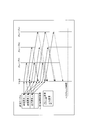
- FIG. 4 shows the functions of the main parts of the second embodiment of the present invention.
- transmission requests belonging to the same group are repeatedly transmitted a predetermined number of times.
- the second and third transmission processes are executed.
- the second and third transmission processes are essentially useless transmission, which is not preferable because communication traffic is congested, transmission of other transmission requests is delayed, and processing load on each unit increases.
- the number of transmission requests is three. However, if the number of slaves is large and the number of transmission requests constituting one group increases, or if the number of repeated transmissions increases to be strong against noise, The problem appears more prominent.
- a normally transmitted transmission frame that has been confirmed to be delivered is a predetermined number of times in which the number of transmissions is set. Even if it has not reached, it will not send after that. As a result, generation of useless transmission frame transmission processing is reduced, and transmission can be performed efficiently and quickly.
- the corresponding transmission request transmission frame is not transmitted (transmission processing is skipped).
- the corresponding request frame can be identified from the transaction ID stored in the ACK frame.
- a transmission completion flag is provided in the transmission table in association with the transmission request, and when the ACK frame is received, the transmission completion flag is turned ON.
- the communication controller 24d reads the transmission table in order from the top when specifying the transmission request to be transmitted, but at this time, the transmission request whose transmission completion flag is ON is not read and the target is transmitted to the next transmission. This can be achieved by shifting to the requirements. Further, the number of remaining transmissions is stored in association with each transmission request stored in the transmission table.
- the initial value is the set number of continuous transmissions, and “3” is set in the examples of FIGS. 2 and 3 described in the first embodiment. Then, every time one transmission is made, 1 is subtracted, and if it becomes “0”, the continuous transmission of this time is completed, and when waiting for an ACK check, if an ACK frame is received on the way, The remaining number of times is updated to “0”. Thus, even after the ACK frame is received, even if the corresponding transmission request comes in the transmission order, the remaining number of times is “0”, so it is skipped and the next transmission request is set as the transmission target. Can do.
- FIG. 1 An example of specific operation is shown in FIG.
- transmission request-1 is addressed to the slave unit of node number # 1
- transmission request-2 is addressed to the slave unit of node number # 2
- transmission request-3 is the node number. It is intended for # 3 slave unit.
- the node numbers of the slave units are set in ascending order from the master unit side. Thereby, the node number # 1 is the slave unit closest to the master unit.
- the I / O unit 30 adjacent to the CPU unit 20 is the node number # 1
- the next I / O unit 30 is the node number # 2
- the high function I / O unit 40 is the node number # 3. It becomes.
- the transmission frame addressed to the slave unit of node number # 2 is once received by the ASIC of the slave unit of node number # 1. It is transferred and received by the slave of node number # 2. Therefore, the longer it takes to propagate the frame, the longer it is from the master unit side (CPU unit 20) (the larger the node number).
- the transmission frame of transmission request-1, the transmission frame of transmission request-2, and the transmission frame of transmission request-3 are sequentially transmitted in that order. Then, the transmission frame of transmission request-1 is normally received by slave # 1, and an ACK frame is returned. Also, the transmission frame of transmission request-2 is transmitted by slave # 1, is normally received by slave # 2, and an ACK frame is returned. This ACK frame is once taken into slave # 1 and transferred to reach the master unit. Similarly, the transmission frame of transmission request-3 reaches slave # 3 via slave # 1 and slave # 2. Then, when it is normally received, the ACK frame reaches the master unit through the reverse path.
- the ACK frame from slave # 1 based on the first transmission process is received by the master unit before transmission of the transmission frame of transmission request-1 in the second transmission process ((1) For the transmission request-1, the second and subsequent transmissions are skipped. Accordingly, the second transmission process is executed for transmission frames of transmission request-2 and transmission request-3.
- the master unit After the completion of the second transmission process and before the transition to the third transmission process, the master unit receives an ACK frame from slave # 2 for the transmission frame of transmission request-2 transmitted in the first transmission process. (Refer to (2)). Accordingly, transmission request-2 is also excluded from the transmission target at this stage, and only the transmission frame of transmission request-3 is transmitted in the third transmission process.
- the master unit receives an ACK frame from slave # 3 for the transmission frame of transmission request-3 transmitted in the first transmission process. (Refer to (3))).
- the ACK check time is set to a time sufficient for returning ACK frames for all transmission frames transmitted in the third transmission process.
- the ACK frame based on the first transmission process is received.
- An ACK frame based on is returned from slave # 2.
- the master unit receives a total of three ACK frames.
- the reception control unit 24b of the master unit receives and discards the ACK frame.
- the number of ACK frames stored in the shared memory unit 24c is one for the same transmission frame, so that unnecessary consumption and storage processing of the memory area can be reduced. Whether or not they are the same ACK frame is determined by whether or not the transaction IDs are the same.
- the number of transmissions of transmission frames of transmission requests belonging to the same group stored in the transmission table is set to be the same, but may be appropriately changed.
- the number of transmissions as an initial value to be set for the remaining number of transmissions is registered for each transmission request, and the value of the remaining number of transmissions is subtracted one by one for each transmission and becomes 0. This can be realized by skipping the transmission request and waiting for the ACK check time to expire when the remaining number of transmissions associated with all transmission requests becomes zero.
- a plurality of transmission tables can be provided. In that case, if grouping is performed for each number of continuous transmissions, it is not necessary to set and manage the number of transmissions for each transmission request, thus simplifying control.
- the number of continuous transmissions should be set differently for each unit depending on the noise environment of the unit.
- an extension unit 60 is attached to the final stage of a block body formed by connecting a plurality of units, and the extension units 60 are connected to each other by an extension cable 14.
- a PLC may be configured.
- the continuous number is set to a large value, and the slave unit connected to the block body including the CPU unit 20 is Since the extension cable is not interposed between the CPU unit 20 and the occurrence of noise is small, it is preferable to reduce the number of consecutive times and reduce the occurrence of useless transmission.
- the continuous number of times is 1, that is, only once is transmitted, and repeated transmission is performed. You may make it not.
- each slave unit is mounted in a slot provided in the base unit. You can do it.
- the CPU unit 20 (master), the I / O unit 30, and the high function I / PO unit 40 (slave) are daisy chain connected. It is not necessary to adopt other communication methods.
- the technique of continuously transmitting a plurality of times can be applied to, for example, the remote I / O terminal 70 connected to the network as shown in FIG. . That is, when looking at the entire network, the PLC 10 becomes a master, and each device connected to the field network 80 becomes a slave, and data transmission / reception is performed between the PLC 10 and the device through master-slave communication on the network. Do.
- This device may be a single device or a plurality of I / O devices in the I / O terminal, such as an I / O terminal (sometimes referred to as a terminal I / O, a terminal device). Some are connected.
- this I / O terminal there is a building block type remote I / O terminal 70 as shown in FIG.
- the remote I / O terminal 70 is configured by connecting a communication unit 71 and one or a plurality of I / O units 72 (slice I / O units).
- the connected units 71 and 72 are connected to an internal bus.
- (System bus) 73 is electrically connected to allow data transmission / reception. Since the I / O unit can be increased or decreased as appropriate, it can be changed and adjusted according to the system configuration.
- the internal bus 73 may be composed of a plurality of systems, similar to the system bus of the above-described embodiment.
- the remote I / O terminal 70 is terminated with an end unit connected to the final stage, and a connection unit is connected to the final stage, and another remote I / O terminal is connected with a connection cable. Can also be connected.
- the communication unit 71 is connected to the communication circuit 25 of the CPU unit 20 of the PLC 10 via the field network 80.
- the communication unit 71 has a function of communicating with a device such as the PLC 10 connected to the field network 80 and a function of communicating with an I / O unit 72 connected to itself.
- the data of the I / O unit 72 is once collected in the communication unit 71 and exchanged with the PLC 10 (CPU unit 20) as a master at once.
- the communication unit 71 becomes a master and the I / O unit 72 becomes a slave, and performs master-slave communication. Then, when communicating with the I / O unit 72 via the internal bus 73, the communication unit 71 transmits a batch of transmission frames continuously a plurality of times, like the CPU unit 20 described above. It is good to implement.
Landscapes
- Engineering & Computer Science (AREA)
- Computer Networks & Wireless Communication (AREA)
- Signal Processing (AREA)
- Physics & Mathematics (AREA)
- General Physics & Mathematics (AREA)
- Automation & Control Theory (AREA)
- Programmable Controllers (AREA)
- Small-Scale Networks (AREA)
Abstract
1つのマスタユニットと複数のスレーブユニットがシステムバスにデジチェーン接続されて構成されるプログラマブルコントローラである。マスタユニットは、異なるスレーブユニット宛の送信フレームを一括りとし、その一連の送信フレームを複数回(図では3回)連続して送信する。これにより、確実に送信できる。
Description
本発明は、プログラマブルコントローラに関するもので、特に、システムバスを用いたユニット間の伝送方式の改良に関する。
FA(Factory Automation)におけるネットワークシステムは、生産工場内に配備された産業ロボットその他の生産設備の入力機器及び出力機器の制御を司る1または複数のPLC(Programmable Logic Controller)と、そのPLCにより動作が制御される機器とが、制御系のネットワークに接続される。
PLCは、CPUユニットや、I/Oユニットなどの各種のユニットを連結して構成される。I/Oユニットには、センサやスイッチなどの入力機器を接続してそれらのオン・オフ信号を入力信号として取り込む入力ユニットやアクチュエータやリレーなどの出力機器を接続してそれらに対して出力信号を送り出す出力ユニット等がある。CPUユニットのMPUが出力ユニットのメモリに書き込んだ出力データに基づいて、出力ユニットが出力機器に対して出力信号を出力する。また、入力機器から入力された入力信号は、入力ユニット内のメモリに格納され、そのメモリに対してCPUユニットのMPUがアクセして入力データを取得する。このように、CPUユニットのMPUが、各ユニットのメモリに対してアクセスしてデータの読み書きをしている。しかし、処理速度の高速化に伴い、MPUが、各ユニットのメモリにアクセスしてデータの読み書きをするのは困難となってきている。
そこで、本発明者は、PLCネットワークケーブルに接続されたノード間の通信技術を利用し、1つのPLCを構成するユニット間でデータの送受を行うことを考えた。具体的には、CPUユニットがマスタで、その他のユニットがスレーブとしてマスタ-スレーブ通信によりデータの送受を行うようにした。また、この種の通信技術では、送信フレームが相手に正常受信された場合に相手先からACKフレームが返送される仕組みを取り、マスタは、一定期間内にACKフレームが返送されてこない場合には、送信できなかったと判断して再送するようにしている。これにより、目的とするデータを相手に確実に送信できるようになる。この種の再送技術は、特許文献1などに開示されている。
ところで、一般のネットワーク接続されたノード間で行われる再送技術をそのままPLCのユニット間のデータ通信に利用することはできない。すなわち、PLCを構成するユニット間のデータの送受は、高速で次々とデータを送りたいという要求がある。しかし、一旦当該データを格納した送信フレームを送り、相手からのACKフレームの返信の有無を確認し、不達の場合に再送し、送信完了の場合に次のデータを格納した送信フレームを送信すると、待ち時間が長くなり、通信技術を用いて高速にデータを送受する意義が無くなる。
さらに、データ通信をする場合にノイズの影響を考慮する必要がある。係るノイズによる送信エラーの回避のために、上記のように再送技術があるが、高速通信をすることで1つの送信フレームを送信するための時間が非常に短くなる。その結果、インパルスノイズのように非常に短時間に単発で発生するようなノイズは、一般的なネットワークケーブルを用いた通信の場合には、1の送信フレームのなかの何ビットかが消失するだけであったが、高速通信を図ると、送信フレーム全体が消失してしまうことになる。また、高速通信をするために、前後の送信フレームを詰めて送信した場合には、インパルスノイズといった短い短発のノイズであっても前後複数個分の送信フレームが損傷し通信エラーとなる恐れがある。
よって、PLCを構成するユニット間の通信を、確実かつ高速に行いたいという課題がある。
上記の課題を解決するために、本発明のプログラマブルコントローラは、(1)1つのマスタユニットと複数のスレーブユニットがシステムバスに接続されて構成されるプログラマブルコントローラであって、前記マスタユニットは、異なるスレーブユニット宛の送信フレームを一括りとして複数回連続して送信する機能を備えるようにした。
本発明のマスタユニットは、異なるスレーブユニット宛の送信フレームを一括りとして複数回連続して送信する。すなわち、1回目の送信処理で、係る一括りの送信フレームを所定の順番で送信する。次いで、2回目の送信処理で、一括りの送信フレームを所定の順番で送信する。以後、設定された複数回分繰り返し送信処理をする。なお、1回目と2回目で送信する順番は、実施形態では、同じにしているが、本発明では必ずしも同じにする必要はない。但し、同じにした方が、処理(制御)が簡単に行えるので好ましい。スレーブユニットは、PLCを構成するユニットであるため、マスタユニットと非常に近く、送信フレームの伝搬時間も短い。また、各ユニットに対し、短時間で順次送信する必要があり、必然的に一括りの複数の送信フレームも、できるだけ送信間隔は短くしたいという要求がある。さらに、高速化の要請から、1つの送信フレームを送信するのに要する時間も短くなる。その結果、インパルスノイズのように比較的短い期間に発生するノイズであっても、1つの送信フレーム全体或いは複数の送信フレームがノイズの影響を受けて正常に送信できない事態を生じるおそれもある。しかし本発明では、上記のように、一括りの送信フレームの送信処理を複数回行うため、同一の送信フレームのみを連続して送信することがないので、仮にノイズにより前後に連続する複数の送信フレームが送信できなくても、同一の送信フレームが全てノイズにより送信できなくなることはない。よって、高速かつ確実に各送信フレームを所望のスレーブユニットに送ることができる。
(2)前記スレーブユニットは、前記送信フレームを正常受信した場合に設定されたレスポンスを返信する機能を備え、前記マスタユニットは、前記レスポンスを受信した場合、前記複数回に満たなくても該当する送信フレームの送信を停止するようにするとよい。設定されたレスポンスは、例えば、実施形態のACKフレームの送信や送信要求フレームに対するINフレームの送信などがある。このようにすると、例えば、マスタユニットに近いスレーブユニットのようにレスポンスが早く戻ってくる場合、複数回の送信フレームを送る前に係るレスポンスが戻ってくる可能性がある。係る場合に、レスポンスを受信したならば、その送信フレームは正しく相手に届いているので、それ以降送るのは無駄である。そこで、レスポンスを受信後は、該当する送信フレームの送信を行わないので、必要な送信フレームのみ送信でき、システムの通信に関する負荷が軽減される。
(3)前記マスタユニットは、同一の送信フレームに対する前記レスポンスを複数回受信した場合、2回目以降は破棄するとよい。返送されてきたレスポンスは、所定の受信処理を実行し、メモリ等に格納される。同一の送信フレームに対するレスポンスを一度受信できれば、その送信フレームが相手に正しく伝達できたことが確認できるので、それ以降のレスポンスの受信処理は、無駄であり、メモリの不要な浪費になり好ましくない。そこで本発明では、係る2回目以降のレスポンスを破棄することで、無駄な処理を実行するのを抑制できる。
(4)前記1つのマスタユニットと複数のスレーブユニットが一体化されたブロック体と、前記複数のスレーブが一体化された延長ブロック体とを備え、前記ブロック体と前記延長ブロック体とは延長ケーブルで接続され、前記複数回連続して送信する回数は、前記ブロック体を構成するスレーブユニット宛の送信フレームよりも、前記延長ブロック体を構成するスレーブユニット宛の送信フレームの方が多く設定することよい。延長ケーブルがあると、その前後でノイズの影響が異なる。つまり、マスタユニットからみて延長ケーブルよりも下流側のスレーブユニットに対する送信フレームの方が、上流側のスレーブユニットに対する送信フレームよりもノイズの影響を受けやすく、正常送信できない確率が高い。従って、係る下流側である延長ブロック体を構成するスレーブユニットへの連続送信回数を多く設定することで、確実に送信することができる。一方、CPUユニットと共に連結されたブロック体を構成するスレーブユニットの場合、1回或いは2回等の少ない回数で正常に伝達される可能性が高い。従って、連続送信する複数回の回数を少なくしても送信が可能であり、それに伴い正常に受信された後も同一フレームを送信し続けるといった無駄な処理の発生を抑制できる。
(5)前記複数回連続して送信する回数は、前記一括りの送信フレームを全て同じにするとよい。そのようにすると、送信回数の管理・制御が一括して行えるので好ましい。
(6)また、前記複数回連続して送信する回数は、前記一括りの送信フレームで異なるようにしてもよい。係る構成にする、スレーブユニットごとに適切な送信回数をセットすることで、より確実に無駄なく送信処理を行うことができる。
(6)また、前記複数回連続して送信する回数は、前記一括りの送信フレームで異なるようにしてもよい。係る構成にする、スレーブユニットごとに適切な送信回数をセットすることで、より確実に無駄なく送信処理を行うことができる。
本発明では、複数回連続して送信フレームを送信するようにしたので、PLCを構成するユニット間の通信を、確実かつ高速に行うことができる。
図1は、本発明のプログラマブルコントローラ(以下、「PLC」)10の第1実施形態を示している。このPLC10は、各種の機能を実現するための複数のユニットを連結して構成される。この複数のユニットは、少なくとも1つのCPUユニット20を有する。更に、本実施形態のPLC10は、I/Oユニット30(入力ユニット、出力ユニット、入出力ユニットなど),高機能I/Oユニット40(高機能入力ユニット、高機能出力ユニット、高機能入出力ユニットなど),エンドユニット50を備えている。図示省略するが、PLC10を構成する各ユニットに対して電源供給を行うための電源ユニットも備えている。もちろん、PLC10を構成するユニットは、上記のものに限ることはなく、実行したい制御に応じて必要なものを適宜取捨選択して構成する。
これらの各ユニットは、ケースの側面にコネクタ15を備える。各ユニットは、コネクタ15同士を連結することで、電気的に接続される。すなわち、コネクタ15には、高速シリアル通信線の一端が接続され、高速シリアル通信線の他端は、ユニットの内部回路(本実施形態ではASIC)に接続される。また、電源線も接続される。これにより、隣接するユニットのコネクタ15同士を連結することで、電源ユニットからのユニットへの電源供給が行えるとともに、ユニット間でデータ通信が行える。
さらにPLC10のユニット間の通信は、ASICを用いて行い、高速化を図っている。そして、本実施形態の高速シリアル通信線で構成されるシステムバスは、下り用システムバス11と上り用システムバス12の2系統で構成される。このように、各システムバス11,12を流れるフレームの方向を固定することで、通信時のフレームの衝突の発生確率を抑制し、より確実かつスムーズに伝送できるようにしている。
CPUユニット20は、FAネットワークを構成する各機器の動作を制御するもので、「共通処理」,「INリフレッシュ」(マスタがスレーブのデータを読み出す処理),「ユーザプログラムの演算実行」,「OUTリフレッシュ」(マスタからスレーブへデータを書き込む処理),「周辺サービス」をサイクリックに実行する。CPUユニット20は、マスタとなり、システムバス11,12で接続された各ユニット(スレーブ)との間の通信を管理する。
CPUユニット20は、MPU21と、EEPROM22と、RAM23と、ASIC24と、通信回路25と、を備えている。EEPROM22は、CPUユニット用のシステムプログラムや、ユーザプログラムや、INデータ・OUTデータ等のIOデータが格納される。MPU21は、CPUユニット用のマイクロプロセッサユニットであり、EEPROM22に格納されているシステムプログラムやユーザプログラムを実行することによってPLC全体を統括制御する。RAM23は、MPU21が動作する際にワークメモリとして使用されるメモリである。
AISC24は、ユーザプログラムの一部を実行する機能を有する。また、本発明との関係で言うと、ASIC24は、他のユニットとの間でマスタ-スレーブ通信を行う機能を有する。すなわち、ASIC24は、MPU21と通信するためのMPUインタフェース部(図示省略)や、スレーブユニットとの間で送受するIOデータ等を格納する共有メモリ部24cや、スレーブユニットとの間でマスタ-スレーブ通信を管理する通信コントローラ部24dや、システムバス11,12に接続され、実際にデータの送受を行う送信制御部24a並びに受信制御部24bを備えている。上述したように、システムバス11,12の伝送方向を一方向に固定したため、送信制御部24aは下り用システムバス11に接続し、受信制御部24bは上り用システムバス12に接続する。
通信回路25は、フィールドネットワークに接続されたリモートI/O等の機器との間で通信する。
通信回路25は、フィールドネットワークに接続されたリモートI/O等の機器との間で通信する。
I/Oユニット30や高機能I/Oユニット40は、センサやスイッチなどの入力機器を接続してそれらのオン・オフ信号を入力信号として取り込む入力ユニットやアクチュエータやリレーなどの出力機器を接続してそれらに対して出力信号を送り出す出力ユニット等である。それらのユニット30,40は、スレーブユニットとなる。
I/Oユニット30は、ASIC31や、自己に接続される外部機器と入力信号や出力信号の送受をするためのインタフェース(図示省略)等を備える。ASIC31は、システムバス11,12に対してデジチェーン接続されている。よって、ASIC31は、下り用システムバス11に接続される送信制御部31a並びに受信制御部31b、上り用システムバス12に接続される送信制御部31c並びに受信制御部31d、通信コントローラ部31e等を備える。ASIC31の通信コントローラ部31eは、下り用システムバス11を伝送されてくるフレームを受信制御部31bで受信すると、所定の処理を実行し、対となる送信制御部31aから下流側のスレーブユニットへ送信する。同様に通信コントローラ部31eは、上り用システムバス12を伝送されてくるフレームを受信制御部31dで受信すると、所定の処理を実行し、対となる送信制御部31cから上流側の隣のユニットへ送信する。もちろん、下り用システムバス11で送られてきたフレームが自己宛のもので、その処理結果としてCPUユニット20にレスポンス/ACKを返す場合、係るレスポンスは、送信制御部31cから上り用システムバス12に送信する。
高機能I/Oユニット40は、上記のI/Oユニット30と同様にASIC41、自己に接続される外部機器と入力信号や出力信号の送受をするためのインタフェース(図示省略)等に加え、MPU44を備える。このMPU44が、より複雑な処理を実行することで、高機能I/Oユニット40が、演算処理,IOリフレッシュ,共通処理,周辺サービス等の一連の処理をサイクリックに実行する。つまり、高機能I/Oユニット40は、自ら接続された出力機器の動作を制御するなどの機能を備え、特殊ユニットと称することもできる。演算処理は、予め設定されたプログラムを実行するものでも良いし、ユーザプログラムを実行するものでもよい。
また、高機能I/Oユニット40のASIC41は、システムバス11,12に対してデジチェーン接続されている。よって、ASIC41は、下り用システムバス11に接続される送信制御部41a並びに受信制御部41b、上り用システムバス12に接続される送信制御部41c並びに受信制御部41d、通信コントローラ部41e等を備える。また、高機能I/Oユニット40はMPU44を備えることから、ASIC41にはMPUインタフェース部を備える。さらに、本実施形態では、この高機能I/Oユニット40がCPUユニット20から最も離れた最終のユニットであるため、その後にエンドユニット50が装着される。そして、高機能I/Oユニット40のASIC41の送信制御部41aは、エンドユニット50内の終端抵抗51に接続される。
次に、本発明の要部となるマスタからのフレーム送信機能について説明する。マスタであるCPUユニット20のASIC24は、各種のフレームを作成し、送信する。この送信するフレームは、例えば、OUTデータを送信するためのOUTフレーム,スレーブに対してINデータを要求する送信要求フレーム,スレーブに対してメッセージデータの送信要求をする送信要求フレーム,アプリケーションで発生した割り込み要因にともない送信する割り込みフレームなどがある。
これらの送信フレームは、例えばMPU21が送信すべきデータをASIC24の共有メモリ部24c内の送信テーブルに格納する。そして、ASIC24の実行タイミングになると、通信コントローラ部24dがそのデータを読み出すと共に、送信制御部24aに与え、ヘッダや訂正符号を付加して符号化し、パラレル/シリアル変換して下り用システムバス11に送信する。また、送信フレームには、送信要求毎の各フレームにユニークなトランザクションIDが付加される。
一方、I/Oユニット30や高機能I/Oユニット40等のスレーブユニットは、受信制御部31b,41bにて送信フレームを受信すると、シリアル/パラレル変換した後、復号化してフレームチェックを行う。チェックが正常と判定されると、自己宛の送信フレームの場合には、送信フレームで送られてきたデータに基づく所定の処理を実行する。
すなわち、OUTフレームの場合、スレーブユニットは、送られてきたOUTデータを基づくOUTリフレッシュを行うとともに、ACKフレームを作成し、送信制御部31c,41cからマスタユニットに向けて送信する。このACKフレームをCPUユニット20のASIC24が受信制御部24bを介して取得すると、先に送信したOUTフレームが受信されたことを認識する。また、送信フレームがINデータを要求する送信要求フレームの場合、スレーブユニットは、最新のINデータを格納したINフレームを作成し、送信制御部31c,41cからマスタに向けて返送する。送信フレームがメッセージデータを要求する送信要求フレームの場合、スレーブユニットは、受信時点で送信可能なメッセージが存在するとそのメッセージを格納したメッセージフレームを作成し、送信制御部31c,41cからママスタに向けて返送する。さらに、送信フレームが割り込みフレームの場合、スレーブユニットのASICは、割り込み要求に応じた処理を行うと共に、ACKフレームを作成し、送信制御部31c,41cからマスタユニットに向けて送信する。このACKフレームには、送信フレームに付加されていたトランザクションIDを付加する。これにより、CPUユニット20は、トランザクションIDをキーにして、受信したACKフレームがどの送信要求についてのものかを認識できる。
また、デジチェーン接続されているため、受信制御部24bで受信した送信フレームは、通信コントローラ部31e,41eに与えられ、最終的に、送信制御部31a,41aにてパラレル-シリアル変換され、伝送路である下り用システムバス11に出力される。
ここで本実施形態では、マスタユニットであるCPUユニット20のASIC24は、共有メモリ部24c内の送信テーブルにセットされた一括りの複数の送信要求を、スレーブユニットからのACKフレームの受信を待つことなく所定の順番で繰り返し指定回数だけ連続して送信する。つまり、例えば、3つの送信要求があり、繰り返し送信回数が3回とすると、ASIC24は、図2(a),図3に示すタイミングで送信処理を実行する。図2では、図示の便宜上、各送信要求の送信フレームを、数字のみ示している。また、各送信フレームは、前後に詰めた状態で次々と送るようにしている。これにより、システムバス上での高速送信が確保され、PLC10を構成する各ユニット間の高速通信が担保される。
まず、ASIC24は、1回目の送信処理として、送信要求-1,送信要求-2,送信要求-3の順番で、各送信要求の送信フレームを作成するとともに送信する。そして、ASIC24は、グループの最後の送信要求-3の送信フレームを送信したならば、2回目の送信処理に移行し、送信要求-1,送信要求-2,送信要求-3の順番で、各送信要求の送信フレームを作成するとともに送信する。その後、3回目の送信処理に移行し、ASIC24は、送信要求-1から順番に送信する。そして、ASIC24は、送信要求-3の送信フレームを送信すると、ACKチェック時間監視用のタイマをスタートさせる。もちろん、一般的に行われる送信の度にACK監視タイマを起動するようにしてもよい。
ASIC24は、ACKフレームを受信すると、それに含まれるトランザクションIDからどの送信要求に対するものかを認識できる。この受信したACKフレームは、共有メモリ部24cの所定のメモリエリアに格納される。そして、ASIC24は、タイマでACKチェック時間が経過した時点で、ACKが必要となる全ての送信要求フレームに対するACKフレーム(或いはINフレーム等のスレーブユニットからのレスポンス)が返送されてきた否かを判断し、送信要求グループに属する全ての送信フレームについての送達確認ができたならば、正常完了する。もちろん、送信フレームの種類によっては、送信のみしてスレーブユニットからのレスポンスを要求しないものもあり、そのような送信フレームについては、ACKフレームがあったとみなすか、監視対象から排除することで対応する。一方、送信フレームは正常に送信できなかったと判断し、CPUユニット20のMPU21およびまたはASIC24は、所定の処理を実行する。もちろん、一般的に行われる送信の度にACK監視タイマを起動するようにした場合には、上記の正常に送信できたか否かの判断もその都度行えばよい。
このように、複数の送信フレームを、順番に繰り返すことで、例えば図2(b)に示すようにインパルスノイズが発生し、連続した複数の送信フレームが正常に送信できない事態が発生しても、複数回送信を繰り返すことで、確実に全ての送信フレームを送ることができる。すなわち、一般のネットワークケーブルで接続されたノード間の通信と相違し、PLCのシステムバス内でのデータ通信であり、しかも、従来よりも高速通信を行うようにしたため、例えば、1つの送信フレームを送信するのに要する時間は、数十nsec~数百nsec程度となり、この時間は、通信速度が速くなるとさらに短くなる。一方、インパルスノイズは、数百nsec以上の時間で発生している。従って、一般的なネットワーク通信でのインパルスノイズの影響は、1つの送信フレーム内の何ビットからの欠落ですむが、本実施形態のPLCでは、送信フレーム全体がエラーとなる。しかも、前後に詰めて連続して送信フレームを送信することから、連続した複数の送信フレームがエラーとなる。そして、図2(b)に示すように、1回目の送信要求-1から2回目の送信要求-1までの4つの送信フレームがエラーになった場合でも、送信要求-2と送信要求-3については、2回目の送信処理でスレーブユニットに送ることができ、また、送信要求-1については3回目の送信処理でスレーブユニットに送ることができる。
これに対し、同じ送信フレームを複数回送信する場合でも、同一の送信要求についての送信フレームを所定回数連続して送信し、次に別の送信要求についての送信フレームを所定回数連続して送信するような場合には、正しく送信できないおそれがある。3つの送信要求の送信フレームを、それぞれ3回ずつ送信した場合、図2(a)に示すように、まず送信要求-1についての送信フレームを3回連続して送信した後、送信要求-2についての送信フレームについての送信処理に移行することになる。すると、上記の図2(b)と同様に先頭から4つ分の送信フレームがノイズで送信できない場合、図2(c)に示すように送信要求-2の2回目の送信から正常送信できるので、送信要求-1については送ることができなくなってしまうという弊害がある。
また、ノイズが無く、送信処理した全ての送信フレームが正しく送られた場合、図2(a)に示すように、本実施形態では、送信要求-1の送信開始から送信要求-2を送信するまでの最短時間T1は、送信フレーム1つ分の送信時間となり、この時間は、繰り返し送信する回数に関係なく一定となる。これに対し、図2(c)に示すように同じ送信フレームを複数回送信する場合、送信要求-1の送信開始から送信要求-2を送信するまでの最短時間T2は、送信フレーム3つ分の送信時間となる。そして、この時間は、繰り返し送信する回数が多くなればなるほど長くなるという問題を生じる。ノイズに強くなるように、繰り返し送信する回数を長くした場合、その差はより顕著に表れる。
また、マスタユニットであるCPUユニット20は、送信フレームには、送信要求毎にユニークなトランザクションIDを付加する。そのため、CPUユニット20は、2回目以降の連続送信時における同一の送信要求についての送信フレームには、初回と同じトランザクションIDを付加する。つまり、送信要求-1についての送信フレームは、3回繰り返し送信する場合、3つとも同じトランザクションIDとなる。
このため、図3に示すように、スレーブユニット(受信側)は、同じトランザクションIDのフレームを複数回受信することがあり、この場合、スレーブユニットは、以下のレスポンスを返送する。すなわち、OUTフレームを受信したスレーブユニットのASICは、その都度ACKフレームを返送する。これにより同一のスレーブからのACKフレームも連続ではなくバラバラにばらけて返送されるためACKもノイズに強くなる。なお、同一の送信フレームを連続して複数回送信した場合には、その送信フレームを受信したスレーブからのACKフレームも連続して送信されることになり、送信時と同様にノイズの影響を受けやすくなる。
また、スレーブユニットのASICは、受信したOUTフレームにて送られてきたOUTデータ(送信要求)については、それを用いたOUTリフレッシュなどすることなくそのまま破棄する。これにより、スレーブユニットは、無駄な更新・書き換え処理を実行しないですむ。
INデータ用の送信要求フレームを受信したスレーブユニットのASICは、最新INデータでINフレームを作成するとともに返送し、メッセージ用の送信要求フレームを受信したスレーブユニットのASICは、受信時点で送信可能なメッセージデータでメッセージフレームを返送する。割り込み要求フレームを受信したスレーブユニットのASICは、前回の割り込み要因に従って処理が行われているので、割り込み要因の更新は行わないが、正常受信を通知するためACKフレームは返送する。
図4は、本発明の第2実施形態の要部の機能を示している。上述した第1実施形態では、同じグループに属する送信要求を、予め定められた回数だけ繰り返し送信している。これにより、例えば1回目の送信処理で全ての送信フレームが目的のスレーブに伝達されたとしても、2回目、3回目の送信処理を実行することになる。この場合、2回目,3回目の送信処理は、本来は無駄な送信となり、通信トラフィックが混み他の送信要求の送信が遅れたり、各ユニットでの処理負荷も増すので好ましくない。さらに、説明の便宜上、送信要求が3つとしているが、スレーブの数が多く、1つのグループを構成する送信要求の数が増えたり、ノイズに強くなるように繰り返し送信する回数が増えると、その問題がより顕著に表れる。
そこで本実施形態では、連続送信の実行中に送達確認がとれ、正常完了したスレーブユニットが確認できた場合、その送達確認できた正常に送信された送信フレームは、送信回数が設定された所定回数に達していなくてもそれ以降は送信しないようにした。これにより、無駄な送信フレームの送信処理の発生が軽減され、効率よく迅速に送信できる。
具体的には、連続送信の実行中にACKフレームを受信した場合、対応する送信要求の送信フレームは送信しない(送信処理をスキップする)ようにする。対応する要求フレームは、ACKフレームに格納されたトランザクションIDから特定できる。スキップ処理は、例えば、送信テーブルに、送信要求と関連付けて送信完了フラグを設け、ACKフレームを受信した場合に当該送信完了フラグをONにする。通信コントローラ部24dは、送信処理対象の送信要求を特定するに際し、送信テーブルを先頭から順に読み出すが、このとき、送信完了フラグがONになっている送信要求は読み出すことなく、対象を次の送信要求に移行することで実現できる。また、送信テーブルに格納される各送信要求に対し、送信残り回数を関連付けて記憶する。初期値は、設定された連続送信回数で、第1実施形態で説明した図2,図3の例では、「3」がセットされる。そして、1回送信するごとに、1ずつ減算し、「0」になったならば今回の連続送信は完了とし、ACKチェック待ちとするようにした場合、途中でACKフレームを受信したならば、当該残り回数を「0」に更新する。これにより、そのACKフレームを受信した後で、対応する送信要求が送信順番に来たとしても、残り回数が「0」になっているのでスキップし、その次の送信要求を送信対象にすることができる。
特に、送信テーブルに多数の送信要求がエントリしてあり、マスタユニットの近くに配置されたスレーブユニットは、送信フレーム・ACKフレームの通信に要する時間が短いので、連続送信の実行中に送達確認が正常完了する可能性が高くなる。
具体的な動作の一例を示すと、図4のようになる。ここでは、ノイズなど発生せず、全ての送信フレームがそれぞれのスレーブユニットに伝達されているものとする。また、「送信要求-1」は、ノード番号#1のスレーブユニット宛のもの、「送信要求-2」は、ノード番号#2のスレーブユニット宛のもの、「送信要求-3」は、ノード番号#3のスレーブユニット宛のものとする。また、スレーブユニットは、マスタユニット側から昇順方式でノード番号が設定されている。これにより、ノード番号#1がマスタユニットに最も近いスレーブユニットである。図1の例では、CPUユニット20に隣接するI/Oユニット30がノード番号#1となり、次のI/Oユニット30がノード番号#2となり、高機能I/Oユニット40がノード番号#3となる。
また、本実施形態では、各ユニットのASICは、デジチェーン接続されているため、ノード番号#2のスレーブユニット宛の送信フレームは、一旦ノード番号#1のスレーブユニットのASICで受信された後、転送されてノード番号#2のスレーブで受信される。よって、マスタユニット側(CPUユニット20)から離れるほど(ノード番号が大きくなるほど)フレームが伝搬されるのに要する時間が長くなる。
係る前提において、1回目の送信処理で、送信要求-1の送信フレーム、送信要求-2の送信フレーム、送信要求-3の送信フレームに対し、その順番で順次送信する。すると、送信要求-1の送信フレームは、スレーブ#1で正常受信され、ACKフレームが返送される。また、送信要求-2の送信フレームは、スレーブ#1で伝送されてスレーブ#2で正常受信され、ACKフレームが返送される。このACKフレームは、一旦スレーブ#1に取り込まれ、転送されることでマスタユニットに到達する。同様に、送信要求-3の送信フレームは、スレーブ#1,スレーブ#2を経てスレーブ#3に至る。そして、正常受信されると、上記の逆の経路を経てACKフレームがマスタユニットに到達する。
図示するように、1回目の送信処理に基づくスレーブ#1からのACKフレームが、2回目の送信処理における送信要求-1の送信フレームの送信前にマスタユニットに受信されているので((1)参照)、送信要求-1について2回目以降の送信はスキップする。これに伴い、2回目の送信処理は、送信要求-2と送信要求-3の送信フレームについて実行する。
2回目の送信処理が完了後、3回目の送信処理に移行する前に、1回目の送信処理で送信した送信要求-2の送信フレームに対するスレーブ#2からのACKフレームがマスタユニットで受信されている((2)参照)。従って、この段階で送信要求-2も送信対象から外れ、3回目の送信処理では送信要求-3の送信フレームのみが送信される。
また、3回目の送信処理の終了後、ACKチェック時間のタイムアップする前に、1回目の送信処理で送信した送信要求-3の送信フレームに対するスレーブ#3からのACKフレームがマスタユニットで受信されている((3)参照))。これにより、スレーブ#3からの送達確認が正常完了したと認識され、今回の送信処理は、全て正常に送達されたことになる。また、ACKチェック時間は、3回目の送信処理で送信される全ての送信フレームに対するACKフレームが返信されてくるのに十分な時間が設定される。
また、図から明らかなように、例えば、2回目の送信処理で送信要求-2を送信した後に1回目の送信処理に基づくACKフレームを受信しているので、その後に、その2回目の送信処理に基づくACKフレームがスレーブ#2から返送されてくる。送信要求-3については、マスタユニットは、合計3回のACKフレームを受信することになる。
そこで、マスタユニットの受信制御部24bは、ACKフレームを受信した後で連続送信のために同じACKフレームをさらに受信した場合、当該ACKフレームを受信破棄する。これにより、共有メモリ部24cに格納されるACKフレームは、同一の送信フレームに対するものは1つとなるのでメモリ領域の無用な消費並びに格納処理を削減できる。同じACKフレームか否かはトランザクションIDが同一であるか否かで判断する。
上記の例では、ACKフレームについて説明したが、INフレーム等を受信した場合でもスレーブユニット側で正常に受信したと判断できるので、上記と同様の送信制御を行う。
また、上述した実施形態では、送信テーブルに格納された同じグループに属する送信要求の送信フレームの送信回数は同じに設定したが、適宜異ならせても良い。この場合、送信要求ごとに残り送信回数にセットする初期値としての送信回数を関連付けて登録し、1回送信するごとにその残り送信回数の値を1つずつ減算し0になったならばその送信要求についてスキップし、全ての送信要求に関連付けられた残り送信回数が0になったならば、ACKチェック時間のタイムアップを待つようにすることで実現できる。また、送信テーブルを複数設けることもできる。その場合に、連続送信回数ごとにグループ分けすると、送信回数を送信要求ごとに設定・管理する必要がないので、制御が簡単になる。
連続送信回数は、ユニットのノイズ環境によりユニット毎に異なる設定とするとよい。例えば、図5に示すように、複数のユニットを連結して構成されるブロック体の最終段に延長ユニット60を取り付け、その延長ユニット60同士を延長ケーブル14により接続することで、複数のブロックからPLCが構成されることがある。この場合、延長ケーブル14以降のスレーブユニットへの送信フレームは、ノイズの影響により通信エラーになる確率が高いので、連続回数を大きい値にし、CPUユニット20を含むブロック体に連結されたスレーブユニットは、CPUユニット20との間に延長ケーブルが介在しないためにノイズの発生も少ないので連続回数を小さくし、無駄な送信の発生を削減すると良い。
また、全てのスレーブユニットに対して2以上の連続回数にする必要はなく、例えば、CPUユニット20に近いスレーブユニットに対しては、連続回数を1,すなわち、1回のみ送信し、繰り返し送信をしないようにしてもよい。
さらにまた、上述した各実施形態では、ユニットの側面同士をコネクタで接続するタイプのものとしたが、本発明はこれに限ることはなく、例えば、各スレーブユニットをベースユニットに設けたスロットに装着するものでも良い。
また、上述した各実施形態では、CPUユニット20(マスタ)とI/Oユニット30,高機能I/POユニット40(スレーブ)とは、デジチェーン接続しているが、本発明は必ずしも係る接続形態を採る必要はなく、他の各種の通信方式をとれる。
また、上記のマスタからスレーブに対してフレームを送信する際に、複数回連続して送信する技術は、たとえば図6に示すようなネットワークに接続されるリモートI/Oターミナル70等にも適用できる。すなわち、ネットワーク全体を見ると、PLC10がマスタとなり、フィールドネットワーク80に接続された各機器がスレーブとなって、PLC10と機器との間で、ネットワークでのマスタ-スレーブ通信をしてデータの送受を行う。この機器には、単独の機器もあれば、I/Oターミナル(ターミナルI/O,ターミナル装置などと称されることもある)のように、そのI/Oターミナルにさらに複数のI/O機器が接続されるものもある。そして、このI/Oターミナルの一つの形態として、図6に示すようにビルディングブロック型のリモートI/Oターミナル70がある。
このリモートI/Oターミナル70は、通信ユニット71と、1または複数のI/Oユニット72(スライスI/Oユニット)とを連結して構成され、それら連結されたユニット71,72は、内部バス(システムバス)73で電気的に接続され、データの送受ができる。I/Oユニットは、適宜増減できるので、システム構成に応じて変更調整できる。この内部バス73は、上述した実施形態のシステムバスと同様に、複数系統で構成しても良い。
また、リモートI/Oターミナル70は、PLC10と同様に、最終段にはエンドユニットが連結されて終端され、また、最終段に接続ユニットを連結するとともに、接続ケーブルで他のリモートI/Oターミナルを接続することもできる。
通信ユニット71は、フィールドネットワーク80を介してPLC10のCPUユニット20の通信回路25に接続される。通信ユニット71は、フィールドネットワーク80に接続されたPLC10等の装置と通信する機能と、自己に連結されたI/Oユニット72と通信する機能を有する。I/Oユニット72のデータは、一旦通信ユニット71に収集され、一括でマスタであるPLC10(CPUユニット20)とデータ交換する。
通信ユニット71とI/Oユニット72との間は、通信ユニット71がマスタとなり、I/Oユニット72がスレーブとなり、マスタ-スレーブ通信を行う。そして、通信ユニット71は、I/Oユニット72との間で内部バス73経由で通信する際に、上述したCPUユニット20と同様に、一括りの送信フレームを複数回連続して送信する技術を実装すると良い。
10 PLC
11 下り用システムバス
12 上り用システムバス
14 延長ケーブル
20 CPUユニット
21 MPU
24 ASIC
30 I/Oユニット
31 ASIC
40 高機能I/Oユニット
41 ASIC
44 MPU
60 延長ユニット
70 リモートI/Oターミナル
71 通信ユニット
72 I/Oユニット
11 下り用システムバス
12 上り用システムバス
14 延長ケーブル
20 CPUユニット
21 MPU
24 ASIC
30 I/Oユニット
31 ASIC
40 高機能I/Oユニット
41 ASIC
44 MPU
60 延長ユニット
70 リモートI/Oターミナル
71 通信ユニット
72 I/Oユニット
Claims (6)
- 1つのマスタユニットと複数のスレーブユニットがシステムバスに接続されて構成されるプログラマブルコントローラであって、
前記マスタユニットは、異なるスレーブユニット宛の送信フレームを一括りとして複数回連続して送信する機能を備えたことを特徴とするプログラマブルコントローラ。 - 前記スレーブユニットは、前記送信フレームを正常受信した場合に設定されたレスポンスを返信する機能を備え、
前記マスタユニットは、前記レスポンスを受信した場合、前記複数回に満たなくても該当する送信フレームの送信を停止するようにしたことを特徴とする請求項1に記載のプログラマブルコントローラ。 - 前記マスタユニットは、同一の送信フレームに対する前記レスポンスを複数回受信した場合、2回目以降は破棄することを特徴とする請求項2に記載のプログラマブルコントローラ。
- 前記1つのマスタユニットと複数のスレーブユニットが一体化されたブロック体と、前記複数のスレーブが一体化された延長ブロック体とを備え、前記ブロック体と前記延長ブロック体とは延長ケーブルで接続され、
前記複数回連続して送信する回数は、前記ブロック体を構成するスレーブユニット宛の送信フレームよりも、前記延長ブロック体を構成するスレーブユニット宛の送信フレームの方が多く設定することを特徴とする請求項1から3のいずれかに記載のプログラマブルコントローラ。 - 前記複数回連続して送信する回数は、前記一括りの送信フレームを全て同じにすることを特徴とする請求項1から4のいずれかに記載のプログラマブルコントローラ。
- 前記複数回連続して送信する回数は、前記一括りの送信フレームで異なるようにしたことを特徴とする請求項1から4のいずれかに記載のプログラマブルコントローラ。
Priority Applications (3)
| Application Number | Priority Date | Filing Date | Title |
|---|---|---|---|
| EP11756180.3A EP2455832B1 (en) | 2010-03-15 | 2011-03-10 | Programmable controller |
| CN201180003350.8A CN102473005B (zh) | 2010-03-15 | 2011-03-10 | 可编程控制器 |
| US13/399,100 US8595400B2 (en) | 2010-03-15 | 2012-02-17 | Programmable controller using master-slave communication |
Applications Claiming Priority (2)
| Application Number | Priority Date | Filing Date | Title |
|---|---|---|---|
| JP2010058252A JP5408445B2 (ja) | 2010-03-15 | 2010-03-15 | プログラマブルコントローラおよびマスタ通信回路 |
| JP2010-058252 | 2010-03-15 |
Related Child Applications (1)
| Application Number | Title | Priority Date | Filing Date |
|---|---|---|---|
| US13/399,100 Continuation US8595400B2 (en) | 2010-03-15 | 2012-02-17 | Programmable controller using master-slave communication |
Publications (1)
| Publication Number | Publication Date |
|---|---|
| WO2011114994A1 true WO2011114994A1 (ja) | 2011-09-22 |
Family
ID=44649089
Family Applications (1)
| Application Number | Title | Priority Date | Filing Date |
|---|---|---|---|
| PCT/JP2011/055679 WO2011114994A1 (ja) | 2010-03-15 | 2011-03-10 | プログラマブルコントローラ |
Country Status (5)
| Country | Link |
|---|---|
| US (1) | US8595400B2 (ja) |
| EP (1) | EP2455832B1 (ja) |
| JP (1) | JP5408445B2 (ja) |
| CN (1) | CN102473005B (ja) |
| WO (1) | WO2011114994A1 (ja) |
Cited By (1)
| Publication number | Priority date | Publication date | Assignee | Title |
|---|---|---|---|---|
| JP2015519801A (ja) * | 2012-04-18 | 2015-07-09 | アクメ パケット インコーポレイテッドAcme Packet, Inc. | リアルタイム通信のための冗長性 |
Families Citing this family (20)
| Publication number | Priority date | Publication date | Assignee | Title |
|---|---|---|---|---|
| US8824333B2 (en) * | 2011-05-31 | 2014-09-02 | Rockwell Automation Technologies, Inc. | Method and apparatus for full duplex serial shifting mode and switch mode data transmission |
| KR101240703B1 (ko) * | 2011-08-17 | 2013-03-11 | 엘에스산전 주식회사 | Plc 네트워크 증설방법 및 이를 이용한 네트워크 증설시스템 |
| US11199824B2 (en) | 2012-01-17 | 2021-12-14 | Fisher-Rosemount Systems, Inc. | Reducing controller updates in a control loop |
| JP4978757B1 (ja) * | 2012-01-24 | 2012-07-18 | オムロン株式会社 | データ設定装置 |
| JP6051547B2 (ja) | 2012-03-15 | 2016-12-27 | オムロン株式会社 | 制御装置 |
| CN104126155B (zh) * | 2012-03-15 | 2017-06-09 | 欧姆龙株式会社 | 控制装置、信息处理装置、控制方法 |
| JP2013206276A (ja) * | 2012-03-29 | 2013-10-07 | Koyo Electronics Ind Co Ltd | マスタ/スレーブ通信方式およびプログラマブルコントローラ |
| JP6263836B2 (ja) * | 2013-01-15 | 2018-01-24 | オムロン株式会社 | 制御装置および制御方法 |
| CN106133624B (zh) * | 2014-03-20 | 2020-06-16 | 费希尔-罗斯蒙特系统公司 | 减少控制回路中的控制器更新 |
| EP3352423B1 (en) * | 2015-09-17 | 2020-08-19 | Kabushiki Kaisha Yaskawa Denki | Industrial device and communication method |
| JP6165286B1 (ja) * | 2016-02-29 | 2017-07-19 | 株式会社安川電機 | モータ制御システム、ロボットシステム、及びモータ制御システムの通信方法 |
| JP6907929B2 (ja) * | 2017-12-27 | 2021-07-21 | 株式会社明電舎 | データ等価方法、プログラマブルコントローラ及び二重化システム |
| JP7083268B2 (ja) * | 2018-03-30 | 2022-06-10 | パナソニック デバイスSunx株式会社 | マルチコントローラシステム |
| DE102018112587A1 (de) * | 2018-05-25 | 2019-11-28 | Valeo Schalter Und Sensoren Gmbh | Verfahren zum Betreiben einer Sensoranordnung in einem Kraftfahrzeug auf Basis eines DSI-Protokolls |
| US11063850B2 (en) * | 2018-08-29 | 2021-07-13 | Ati Technologies Uls | Slave-to-master data and out-of-sequence acknowledgements on a daisy-chained bus |
| WO2020131716A1 (en) * | 2018-12-17 | 2020-06-25 | Graco Minnesota Inc. | Large packet daisy chain serial bus |
| US11704257B1 (en) | 2022-04-15 | 2023-07-18 | Graco Minnesota Inc. | System provisioning using virtual peripherals |
| JP7059973B2 (ja) | 2019-03-15 | 2022-04-26 | オムロン株式会社 | 制御システム、装置および制御方法 |
| JP7275940B2 (ja) * | 2019-07-08 | 2023-05-18 | オムロン株式会社 | 制御プログラムおよび方法 |
| JP2021144550A (ja) * | 2020-03-13 | 2021-09-24 | 三菱電機エンジニアリング株式会社 | 監視制御モジュール |
Citations (4)
| Publication number | Priority date | Publication date | Assignee | Title |
|---|---|---|---|---|
| JPH0897854A (ja) * | 1994-09-28 | 1996-04-12 | Hitachi Ltd | 通信機能付携帯端末装置およびデータ自動配信システム |
| JP2001195325A (ja) * | 2000-01-14 | 2001-07-19 | Sony Corp | 電子メールの着信通知方法および電子メール端末機 |
| JP2001237883A (ja) * | 2000-02-23 | 2001-08-31 | Sony Corp | マルチキャスト通信システム及び方法、並びに、データ通信装置及びデータ通信方法 |
| JP2007128536A (ja) * | 2005-06-09 | 2007-05-24 | Omron Corp | 通信マスタ局の起動時制御方法 |
Family Cites Families (9)
| Publication number | Priority date | Publication date | Assignee | Title |
|---|---|---|---|---|
| US5933478A (en) | 1994-09-28 | 1999-08-03 | Hitachi, Ltd. | Data transfer system and handheld terminal device used therefor |
| US7050860B2 (en) * | 2001-06-22 | 2006-05-23 | Omron Corporation | Safety network system, safety slave, and communication method |
| JP3799326B2 (ja) | 2002-12-02 | 2006-07-19 | Necインフロンティア株式会社 | パケット送信方式及びパケット受信方式 |
| KR100930770B1 (ko) * | 2003-06-04 | 2009-12-09 | 미쓰비시덴키 가부시키가이샤 | 송신기 및 통신 방법 |
| US7673060B2 (en) * | 2005-02-01 | 2010-03-02 | Hewlett-Packard Development Company, L.P. | Systems and methods for providing reliable multicast messaging in a multi-node graphics system |
| JP3925660B2 (ja) * | 2005-06-09 | 2007-06-06 | オムロン株式会社 | 通信マスタ局の起動時制御方法 |
| US7561599B2 (en) * | 2005-09-19 | 2009-07-14 | Motorola, Inc. | Method of reliable multicasting |
| US7742495B2 (en) * | 2006-11-20 | 2010-06-22 | Broadcom Corporation | System and method for retransmitting packets over a network of communication channels |
| DE102007046178A1 (de) * | 2007-09-26 | 2009-04-09 | Phoenix Contact Gmbh & Co. Kg | Steuerungsblock mit einer Punkt-zu-Punkt-Kommunikation zwischen einem an einen Datenbus anzuschaltenden Steuerungs-Mastermodul und Erweiterungs-Slavenmodulen |
-
2010
- 2010-03-15 JP JP2010058252A patent/JP5408445B2/ja active Active
-
2011
- 2011-03-10 CN CN201180003350.8A patent/CN102473005B/zh active Active
- 2011-03-10 EP EP11756180.3A patent/EP2455832B1/en active Active
- 2011-03-10 WO PCT/JP2011/055679 patent/WO2011114994A1/ja active Application Filing
-
2012
- 2012-02-17 US US13/399,100 patent/US8595400B2/en active Active
Patent Citations (4)
| Publication number | Priority date | Publication date | Assignee | Title |
|---|---|---|---|---|
| JPH0897854A (ja) * | 1994-09-28 | 1996-04-12 | Hitachi Ltd | 通信機能付携帯端末装置およびデータ自動配信システム |
| JP2001195325A (ja) * | 2000-01-14 | 2001-07-19 | Sony Corp | 電子メールの着信通知方法および電子メール端末機 |
| JP2001237883A (ja) * | 2000-02-23 | 2001-08-31 | Sony Corp | マルチキャスト通信システム及び方法、並びに、データ通信装置及びデータ通信方法 |
| JP2007128536A (ja) * | 2005-06-09 | 2007-05-24 | Omron Corp | 通信マスタ局の起動時制御方法 |
Non-Patent Citations (1)
| Title |
|---|
| See also references of EP2455832A4 * |
Cited By (2)
| Publication number | Priority date | Publication date | Assignee | Title |
|---|---|---|---|---|
| JP2015519801A (ja) * | 2012-04-18 | 2015-07-09 | アクメ パケット インコーポレイテッドAcme Packet, Inc. | リアルタイム通信のための冗長性 |
| US9531503B2 (en) | 2012-04-18 | 2016-12-27 | Acme Packet, Inc. | Redundancy for real time communications |
Also Published As
| Publication number | Publication date |
|---|---|
| CN102473005A (zh) | 2012-05-23 |
| EP2455832A4 (en) | 2014-03-05 |
| US8595400B2 (en) | 2013-11-26 |
| EP2455832B1 (en) | 2016-07-13 |
| US20120179849A1 (en) | 2012-07-12 |
| JP2011192068A (ja) | 2011-09-29 |
| CN102473005B (zh) | 2016-06-15 |
| JP5408445B2 (ja) | 2014-02-05 |
| EP2455832A1 (en) | 2012-05-23 |
Similar Documents
| Publication | Publication Date | Title |
|---|---|---|
| JP5408445B2 (ja) | プログラマブルコントローラおよびマスタ通信回路 | |
| JP2011192068A5 (ja) | プログラマブルコントローラおよびマスタ通信回路 | |
| US9836038B2 (en) | Control device, and control method for link activating and deactivating | |
| JP5794449B2 (ja) | プログラマブルコントローラ | |
| JP6376229B2 (ja) | 通信システム、通信装置および通信方法 | |
| EP2169487B1 (en) | Industrial controller with coordination of network transmissions using global clock | |
| JP2014138206A (ja) | 制御装置および制御方法 | |
| KR101179431B1 (ko) | 이더캣 네트워크 시스템 및 이의 운용 방법 | |
| JP5570556B2 (ja) | Ioユニットと通信を行う数値制御装置 | |
| JP6629361B2 (ja) | プログラマブルロジックコントローラ | |
| US20230161719A1 (en) | Processing of process data | |
| US8578077B2 (en) | Group master communication system and method for serially transmitting data in automation systems | |
| JP4458278B2 (ja) | 通信サイクル制御方法 | |
| CN112147957B (zh) | 菊花式链接点对点链接传感器 | |
| JP5609075B2 (ja) | サーボモータ制御ネットワークとその通信方法 | |
| JP5815660B2 (ja) | 数値制御システム | |
| US11695833B2 (en) | Method for data communication between subscribers in an automation network, master subscriber for an automation network, and automation network | |
| TWI821680B (zh) | 分散控制系統及具備有此之半導體檢查裝置 | |
| KR101273812B1 (ko) | 피엘씨 일체형 제어모듈 및 이를 이용한 피엘씨 제어 시스템 | |
| JP5223582B2 (ja) | メッセージ伝送装置及びメッセージ伝送方法 | |
| JP2006262117A (ja) | スイッチシステムおよびループ転送方法 | |
| JP2019004400A (ja) | アドレス設定装置およびシステム | |
| JP2022144019A (ja) | 電源システム | |
| JP2016178475A (ja) | 通信システムおよび中継制御方法 | |
| JP2006345171A (ja) | データ伝送方法およびデータ伝送システム |
Legal Events
| Date | Code | Title | Description |
|---|---|---|---|
| WWE | Wipo information: entry into national phase |
Ref document number: 201180003350.8 Country of ref document: CN |
|
| 121 | Ep: the epo has been informed by wipo that ep was designated in this application |
Ref document number: 11756180 Country of ref document: EP Kind code of ref document: A1 |
|
| REEP | Request for entry into the european phase |
Ref document number: 2011756180 Country of ref document: EP |
|
| WWE | Wipo information: entry into national phase |
Ref document number: 2011756180 Country of ref document: EP |
|
| NENP | Non-entry into the national phase |
Ref country code: DE |