WO2011114474A1 - 判定装置、判定システム、判定方法及びコンピュータプログラム - Google Patents
判定装置、判定システム、判定方法及びコンピュータプログラム Download PDFInfo
- Publication number
- WO2011114474A1 WO2011114474A1 PCT/JP2010/054597 JP2010054597W WO2011114474A1 WO 2011114474 A1 WO2011114474 A1 WO 2011114474A1 JP 2010054597 W JP2010054597 W JP 2010054597W WO 2011114474 A1 WO2011114474 A1 WO 2011114474A1
- Authority
- WO
- WIPO (PCT)
- Prior art keywords
- data
- similarity
- tag
- determination
- region
- Prior art date
- Legal status (The legal status is an assumption and is not a legal conclusion. Google has not performed a legal analysis and makes no representation as to the accuracy of the status listed.)
- Ceased
Links
Images



Classifications
-
- G—PHYSICS
- G06—COMPUTING OR CALCULATING; COUNTING
- G06K—GRAPHICAL DATA READING; PRESENTATION OF DATA; RECORD CARRIERS; HANDLING RECORD CARRIERS
- G06K7/00—Methods or arrangements for sensing record carriers, e.g. for reading patterns
- G06K7/10—Methods or arrangements for sensing record carriers, e.g. for reading patterns by electromagnetic radiation, e.g. optical sensing; by corpuscular radiation
- G06K7/10009—Methods or arrangements for sensing record carriers, e.g. for reading patterns by electromagnetic radiation, e.g. optical sensing; by corpuscular radiation sensing by radiation using wavelengths larger than 0.1 mm, e.g. radio-waves or microwaves
- G06K7/10316—Methods or arrangements for sensing record carriers, e.g. for reading patterns by electromagnetic radiation, e.g. optical sensing; by corpuscular radiation sensing by radiation using wavelengths larger than 0.1 mm, e.g. radio-waves or microwaves using at least one antenna particularly designed for interrogating the wireless record carriers
- G06K7/10356—Methods or arrangements for sensing record carriers, e.g. for reading patterns by electromagnetic radiation, e.g. optical sensing; by corpuscular radiation sensing by radiation using wavelengths larger than 0.1 mm, e.g. radio-waves or microwaves using at least one antenna particularly designed for interrogating the wireless record carriers using a plurality of antennas, e.g. configurations including means to resolve interference between the plurality of antennas
-
- G—PHYSICS
- G06—COMPUTING OR CALCULATING; COUNTING
- G06K—GRAPHICAL DATA READING; PRESENTATION OF DATA; RECORD CARRIERS; HANDLING RECORD CARRIERS
- G06K7/00—Methods or arrangements for sensing record carriers, e.g. for reading patterns
- G06K7/10—Methods or arrangements for sensing record carriers, e.g. for reading patterns by electromagnetic radiation, e.g. optical sensing; by corpuscular radiation
- G06K7/10009—Methods or arrangements for sensing record carriers, e.g. for reading patterns by electromagnetic radiation, e.g. optical sensing; by corpuscular radiation sensing by radiation using wavelengths larger than 0.1 mm, e.g. radio-waves or microwaves
- G06K7/10366—Methods or arrangements for sensing record carriers, e.g. for reading patterns by electromagnetic radiation, e.g. optical sensing; by corpuscular radiation sensing by radiation using wavelengths larger than 0.1 mm, e.g. radio-waves or microwaves the interrogation device being adapted for miscellaneous applications
- G06K7/10415—Methods or arrangements for sensing record carriers, e.g. for reading patterns by electromagnetic radiation, e.g. optical sensing; by corpuscular radiation sensing by radiation using wavelengths larger than 0.1 mm, e.g. radio-waves or microwaves the interrogation device being adapted for miscellaneous applications the interrogation device being fixed in its position, such as an access control device for reading wireless access cards, or a wireless ATM
- G06K7/10425—Methods or arrangements for sensing record carriers, e.g. for reading patterns by electromagnetic radiation, e.g. optical sensing; by corpuscular radiation sensing by radiation using wavelengths larger than 0.1 mm, e.g. radio-waves or microwaves the interrogation device being adapted for miscellaneous applications the interrogation device being fixed in its position, such as an access control device for reading wireless access cards, or a wireless ATM the interrogation device being arranged for interrogation of record carriers passing by the interrogation device
-
- G—PHYSICS
- G06—COMPUTING OR CALCULATING; COUNTING
- G06K—GRAPHICAL DATA READING; PRESENTATION OF DATA; RECORD CARRIERS; HANDLING RECORD CARRIERS
- G06K7/00—Methods or arrangements for sensing record carriers, e.g. for reading patterns
- G06K7/10—Methods or arrangements for sensing record carriers, e.g. for reading patterns by electromagnetic radiation, e.g. optical sensing; by corpuscular radiation
- G06K7/10009—Methods or arrangements for sensing record carriers, e.g. for reading patterns by electromagnetic radiation, e.g. optical sensing; by corpuscular radiation sensing by radiation using wavelengths larger than 0.1 mm, e.g. radio-waves or microwaves
- G06K7/10366—Methods or arrangements for sensing record carriers, e.g. for reading patterns by electromagnetic radiation, e.g. optical sensing; by corpuscular radiation sensing by radiation using wavelengths larger than 0.1 mm, e.g. radio-waves or microwaves the interrogation device being adapted for miscellaneous applications
- G06K7/10415—Methods or arrangements for sensing record carriers, e.g. for reading patterns by electromagnetic radiation, e.g. optical sensing; by corpuscular radiation sensing by radiation using wavelengths larger than 0.1 mm, e.g. radio-waves or microwaves the interrogation device being adapted for miscellaneous applications the interrogation device being fixed in its position, such as an access control device for reading wireless access cards, or a wireless ATM
- G06K7/10425—Methods or arrangements for sensing record carriers, e.g. for reading patterns by electromagnetic radiation, e.g. optical sensing; by corpuscular radiation sensing by radiation using wavelengths larger than 0.1 mm, e.g. radio-waves or microwaves the interrogation device being adapted for miscellaneous applications the interrogation device being fixed in its position, such as an access control device for reading wireless access cards, or a wireless ATM the interrogation device being arranged for interrogation of record carriers passing by the interrogation device
- G06K7/10435—Methods or arrangements for sensing record carriers, e.g. for reading patterns by electromagnetic radiation, e.g. optical sensing; by corpuscular radiation sensing by radiation using wavelengths larger than 0.1 mm, e.g. radio-waves or microwaves the interrogation device being adapted for miscellaneous applications the interrogation device being fixed in its position, such as an access control device for reading wireless access cards, or a wireless ATM the interrogation device being arranged for interrogation of record carriers passing by the interrogation device the interrogation device being positioned close to a conveyor belt or the like on which moving record carriers are passing
Definitions
- the present application relates to a determination device, a determination system, a determination method, and a computer program for determining a passing area of an IC tag.
- RFID Radio Frequency IDentification
- RFID has an active type in which a tag has a built-in battery and power for operation is supplied internally, and a passive type that does not have a built-in battery and operates by power supplied by a high frequency transmitted from a reader device. And exist.
- the passive type without a built-in battery can be provided at a relatively low price compared to the active type, and is expected to be used in various fields including the logistics field. Further, when the UHF band (860 to 960 MHz) is used as the RFID frequency band, a passive type has a wider reading range than other frequency bands, and a plurality of tags can be read at a time. For this reason, for example, in the physical distribution field, a plurality of tags attached to a large number of articles can be collectively read and inspected.
- tag information that is not intended by the administrator may be read.
- the tag of the article that is usually placed at a position that is not readable from the inspection gate is reflected by the radio wave reflected on the forklift when the forklift passes near the article, The tag information may be read.
- a plurality of gates are juxtaposed, there is a possibility that the tag of an article that has entered the adjacent gate may be read, and an erroneous determination may occur.
- unnecessary tags may be eliminated by performing filtering based on the ID stored in the tag.
- the pallet tag is obtained by knowing the type data representing the type of article in advance. Can be excluded.
- the inventors of the present application previously collected data in a reader (reading device) and a control system that repeatedly read data from a tag in a communicable area in a contactless manner in a previous application.
- the result of clustering based on the similarity given to the time-series data from the time-series data of the read results is used as reference data, and the read data is classified into necessary data or unnecessary data by calculating the similarity with the reference data.
- a method is disclosed (see Patent Documents 2 and 3).
- JP 2005-275960 A Japanese Patent Application No. 2008-298770 Japanese Patent Application No. 2009-999924
- the previous application is premised on a processing mode by a single reader or a processing mode in which a plurality of readers are controlled by a single host computer.
- the conventional method assumes that all readers operate in the same manner as when the reference data is collected.
- the determination accuracy deteriorates on the assumption that the reading results are integrated.
- the present application prepares not only a cluster of desirable reading patterns (assumed pattern) as in the past but also a cluster of undesirable reading patterns as reference data used for the determination for each determination point. It is an object of the present invention to provide a determination device, a determination system, a determination method, and a computer program that perform determination based on the similarity between both reading patterns.
- the determination apparatus disclosed in the present application acquires data from a detector that outputs data corresponding to a detection state of a detection object that has passed through a first region or a second region different from the first region in time series.
- a storage unit for storing second reference data indicating data to be output by the detector in the first region, data acquired by the data acquisition unit, and first and second references stored in the storage unit A similarity determination unit that determines the degree of similarity with data, and a passage region determination unit that determines whether or not the detected object has passed through the first region based on a determination result by the similarity determination unit.
- the present application not only the similarity to the reference data set for the area to be originally detected (first area) but also the reference data set for the area not to be detected (second area). It is possible to determine whether or not the detected object has passed through the first region as the determination material, and the erroneous determination can be eliminated.
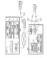
- FIG. 1 is a schematic diagram illustrating an overall configuration of an IC tag reading system according to Embodiment 1.
- FIG. It is a schematic diagram explaining the specific example of a determination area. It is a block diagram explaining the hardware constitutions of a high-order server and a reader
- FIG. FIG. 1 is a schematic diagram showing the overall configuration of the IC tag reading system according to the first embodiment.
- the IC tag reading system according to the first embodiment includes a host server 100, readers 200A and 200B, antennas ANT1 to ANT8, and an IC tag 10.
- readers 200A and 200B do not need to be distinguished from each other, they are referred to as the reader 200.
- the antennas ANT1 to ANT8 do not need to be distinguished from each other, the antennas are described. It shall be described as ANT.
- the host server 100 aggregates the information of the IC tag 10 read by the reader 200 and passes it to the business application.
- the host server 100 and the reader 200 are connected by a wired or wireless LAN, WAN, or other network.
- a plurality of antennas ANT are connected to the reader 200, and data is transmitted to and received from the IC tag 10 by transmitting and receiving commands and responses through wireless communication via the antenna ANT.
- Command / response transmission / reception is performed according to a predetermined protocol.
- a standard such as ISO 18000-6 type C is used as a standard protocol for UHF band IC tags using a communication frequency band of 860 to 960 MHz.
- the reader 200 operates autonomously and repeatedly reads the IC tag 10 according to a predetermined condition.
- the reader 200 communicates with one or a plurality of IC tags 10 in a range where radio waves reach with a constant radio wave intensity from the connected antenna ANT.
- the reader 200 returns the data received from the IC tag 10 to the upper server 100 at a predetermined timing.
- the host server 100 processes the data transmitted from the reader 200 according to a program given in advance.
- the IC tag 10 includes a memory that stores unique identification data (hereinafter referred to as ID), an IC chip that executes predetermined processing, an antenna that enables wireless communication, and the like.
- ID unique identification data
- the IC tag 10 is affixed to an article to be identified by an ID or is carried by a person. Further, the IC tag 10 may store data related to the attachment target (for example, the type of article, the date of manufacture, etc.).
- the IC tag 10 described in the present embodiment is of a radio wave system using a UHF band communication frequency band, and generates a current by receiving a high frequency transmitted from the antenna ANT of the reader 200. .
- the generated current is supplied to each part of the IC tag 10 as a supply voltage adjusted after rectification, and the IC tag 10 becomes operable. Note that the above operation relates to a passive IC tag that does not incorporate a battery, but an active IC tag that incorporates a battery can also be used.
- a plurality of antennas ANT connected to the reader 200 handle the logical sum area of the reading range of the antenna ANT as the determination areas A1 to A4.
- the determination area A1 is formed by the two antennas ANT1 and ANT2 as the reading area of the IC tag 10 passing through the gate G1 is shown.
- one antenna area ANT is in charge of one determination area, but one antenna ANT may be in charge of one determination area.
- the antenna may be configured to handle one determination area.
- the eight antennas ANT1 to ANT8 are managed by the two readers 200A and 200B. However, the number of antennas and the number of readers can be set as appropriate.
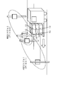
- FIG. 2 is a schematic diagram illustrating a specific example of the determination areas A1 and A2.
- the determination area A1 is, for example, a gate G1 through which a forklift or a carriage that carries an article with the IC tag 10 attached passes.
- a plurality of gates G1 and G2 are installed to load articles on trucks with different delivery destinations, and antennas ANT1 to ANT4 are installed to read the IC tag 10 at each gate G1 and G2. Is done.
- the identification information of the gates G1 and G2 is managed by the reader 200A and the upper server 100 as determination areas A1 and A2. The same applies to determination areas A3 and A4 not shown in FIG.
- FIG. 3 is a block diagram illustrating the hardware configuration of the host server 100 and the reader 200.
- the upper server 100 includes a control unit 101, a ROM (Read Only Memory) 102, a RAM (Random Access Memory) 103, a communication unit 104, a storage unit 105, a display unit 106, and an operation unit 107, which are connected to each other via a bus. It is connected.
- ROM Read Only Memory
- RAM Random Access Memory
- the control unit 101 includes a CPU (Central Processing Unit) or an MPU (Micro Processing Unit). When the MPU is provided, the ROM 102 and the RAM 103 may be incorporated in the control unit 101. The control unit 101 appropriately reads out and executes the computer program stored in the ROM 102 or the storage unit 105 on the RAM 103 according to a predetermined timing, and controls the operation of each hardware unit described above.
- a CPU Central Processing Unit
- MPU Micro Processing Unit
- the ROM 102 stores in advance a computer program necessary for realizing the determination method of the present application and a computer program necessary for operating each hardware unit described above.
- the RAM 103 is, for example, a DRAM (Dynamic RAM), an SRAM (Static RAM), a flash memory, or the like, and various data (for example, calculation results, read data, various parameters) generated when the control unit 101 executes the computer program. Is temporarily stored.
- DRAM Dynamic RAM
- SRAM Static RAM
- flash memory or the like
- various data for example, calculation results, read data, various parameters
- the communication unit 104 performs data communication with the reader 200 via a wired or wireless network, and receives data of the IC tag 10 read by the reader 200.
- the operation unit 107 includes an input interface necessary for the operator to operate the upper server 100.
- the display unit 106 is, for example, a liquid crystal display, and displays the operation status of the upper server 100, information input via the operation unit 107, information to be notified to the operator, and the like according to instructions from the control unit 101. .
- the display unit 106 and the operation unit 107 provide an interface with the operator.
- the host server 100 may be configured to perform operation input from other devices and output to other devices via a network, and the display unit 106 and the operation unit 107 are not necessarily provided.
- the storage unit 105 is a non-volatile storage device such as a hard disk or a flash memory.
- the storage unit 105 stores reference data collected from the reader 200 and the like.
- the computer program necessary for realizing the determination method of the present application and the computer program necessary for operating each part of the hardware are stored in the ROM 102.
- these computer programs are stored in the storage unit 105. It is good also as a structure stored in.
- the reader 200 includes a control unit 201, a communication unit 202, an RF unit 203, a storage unit 204, and an external input / output unit 206, which are connected to each other via a bus.
- An antenna ANT that acquires data from the IC tag 10 is connected to the RF unit 203.
- antennas ANT1 to ANT4 are connected to RF section 203 of reader 200A
- antennas ANT5 to ANT8 are connected to RF section 203 of reader 200B.
- the control unit 201 of the reader 200 performs wireless communication with the IC tag 10 via the RF unit 203 and the antenna ANT according to the operation procedure stored in advance in the storage unit 204.
- the storage unit 204 is a non-volatile storage device such as a hard disk or a flash memory.
- the external input / output unit 206 receives an input from the sensor 250 such as an optical sensor or a tactile sensor, and provides an interface for outputting a signal to a control device of an external device such as a PLC (Programmable Logic Controller).
- the sensor 250 detects the passage of an article or a person
- the reader 200 can recognize the passage of the article or a person via the external input / output unit 206, and controls the start / end of the tag reading process. Can do.
- the reader 200 transmits / receives data to / from the IC tag 10 according to the following procedure.
- the reader 200 first searches for an IC tag 10 existing in the readable range of the antenna ANT (event). That is, the reader 200 outputs a radio signal indicating a search command from the antenna ANT.
- the IC tag 10 that has received the search command transmitted by the reader 200 is supplied with a voltage to each unit and becomes operable, and then transmits its identification data (tag ID) to the reader 200 as a response to the search command.
- the reader 200 can identify the tag ID of the IC tag 10, and data can be transmitted and received between the reader 200 and the IC tag 10.
- the reader 200 transmits a search command and there are a plurality of IC tags 10, 10,..., 10 in the communicable range of the antenna ANT, the plurality of IC tags 10, 10,. Since the responses are transmitted at the same time, the responses may interfere with each other, and the reader 200 may not receive the response (collision).
- a collision avoidance function is implemented in the reader 200 and the IC tag 10.
- temporary response suppression from the IC tag 10 is performed according to a collision avoidance protocol defined between the reader 200 and the IC tag 10, and finally from one remaining IC tag 10.
- the reader 200 receives a response including the tag ID, the IC tag 10 is identified.
- the same collision avoidance procedure is performed in accordance with commands continuously transmitted from the reader 200, and tag IDs are identified one by one. As a result, the reader 200 can obtain all the tag IDs of the IC tags 10 that can respond.
- data reading and writing are further performed by transmitting and receiving data reading commands and data writing commands between the reader 200 and the IC tag 10. Can be done.
- the reader 200 repeatedly transmits a search command autonomously according to a condition specified in advance.
- the IC tag 10 transmits stored data every time a search command is received. Therefore, each time the search command is sent, the reader 200 responds to the IC tag 10 existing within the readable range of the connected antenna ANT every time. If there is no problem in the radio wave environment, the reader 200 responds to the number of times each IC tag 10 responds. Will be received.
- the reader 200 and the host server 100 perform unnecessary tag reading filtering processing using the time-series pattern received repeatedly for each tag ID.
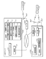
- FIG. 4 is a block diagram illustrating the functional configuration of the upper server 100 and the reader 200.
- the application 111 stored in the host server 100 performs processing corresponding to various operations such as production, distribution, and inventory management using the tag information read by the reader 200.
- the reference data generation unit 112 generates reference data for filtering from information such as an assumed pattern that is an ideal reading pattern collected by the reader 200 in advance. The generated reference data is recorded in the storage unit 105. Details of the reference data will be described later.
- the storage unit 105 stores information on the reader 200 (reader information) that allows the host server 100 to receive tag data, and information on determination areas (determination area information) that each reader 200 is responsible for.
- the tag data processing unit 113 determines a final reading area from the determination area based on information such as the similarity calculation result between the data such as the tag ID reported from the reader 200 and the reference data.
- the unit 114 is provided.
- the final reading area means gate identification information indicating a gate having a high possibility (accuracy) that the detected IC tag 10 has passed among the gates G1 to G4.
- the determination area means gate identification information of a gate where the antenna ANT included in the reader 200 that is communicably connected to the upper server 100 via a network. Information regarding the reader 200 that is communicably connected to the upper server 100 via a network can be obtained by referring to the reader information stored in the storage unit 105 of the upper server 100.
- the reader 200 operates autonomously according to the reading control setting set prior to operation, and reads the IC tag 10.
- the reading control setting is stored in the storage unit 204 of the reader 200, and one or a plurality of antennas ANT to be used and their order, the number and time of repeatedly transmitting a search command from each antenna ANT, and other than the ID for the read tag ID In the case of reading and writing the data, the designation of the read / write command is described.
- the reading control unit 211 loads the contents of the reading control setting from the storage unit 204, and transmits a search (inventory) command for the IC tag 10 to the RF unit 203 corresponding to each antenna ANT according to the described control procedure. The response from the IC tag 10 is read.
- the read tag ID time-series data is compared with the reference data stored in the storage unit 204 as time-series data collected in advance for each tag ID by the similarity determination unit 212, and the optimum cluster data is obtained. Similarity is calculated. The similarity determination process will be described in detail later.
- time series data acquired by the reader 200 by repeatedly reading the tag ID will be described.
- the reader 200 repeatedly issues a search (inventory) command while repeatedly using one or more antennas ANT according to the reading control setting stored in the storage unit 204.
- the response result of the search command is held in the storage unit 204 in time series in order for each read tag ID and for each determination area.
- the time-series data held in the storage unit 204 is called a read pattern.
- FIG. 5 is a schematic diagram showing an example of a reading pattern.
- FIG. 5A shows an example of a reading pattern in the determination area A1 (gate G1)
- FIG. 5B shows an example of a reading pattern in the determination area A2 (gate G2).
- the two antennas ANT1 and ANT2 are in charge of the determination area A1
- the two antennas ANT3 and ANT4 are in charge of the determination area A2.
- T1, T1 + a1,..., T1 + a11 in the row direction represent a time series, and indicate the time when the reader 200A issues a search command.
- the reader 200A repeatedly issues a search command while switching the antenna that issues the search command at each time in the order of the antennas ANT1, ANT2, ANT3, and ANT4.
- the search command is not necessarily issued at a constant time interval, but is issued at an appropriate timing controlled by the control unit 201 of the reader 200.
- a1, a2,..., A11 are times of about several tens of msec.
- the tag ID of the read IC tag 10 is described at the left end in the column direction (vertical axis) of the read pattern.
- the example shown in FIG. 5 indicates that the IC tag 10 having the tag IDs id1 to id4 has been read.
- Symbols A to C shown in each column of the read pattern are symbols indicating the antennas ANT1, ANT2, and ANT3, respectively. Although the symbol indicating the antenna ANT4 is D, the example shown in FIG. 5 indicates that the antenna ANT4 has not performed reading. A blank column indicates that the IC tag 10 has not been read.
- the reading pattern shown in FIG. 5A is obtained when the antenna ANT1 issues a search command at times T1, T1 + a4, T1 + a8, and as a result, the IC tag 10 having the tag ID id1 and the IC tag 10 having the tag ID id2. , And at time T1 + a1, T1 + a5, T1 + a9, as a result of the antenna ANT2 issuing a search command, the IC tag 10 having the id3 tag ID and the IC tag 10 having the id4 tag ID are read. On the other hand, the reading pattern shown in FIG.
- a blank In order to display each line of the read pattern as a symbol string, a blank can be represented by an underscore “_”, and for example, a line of id1 in the determination area A1 can be represented as “A___A___A___”. Further, when the antenna output is changed in two stages, it may be expressed as an uppercase “A” when the output is large, and may be expressed as a lowercase “a” when the output is small.
- the time series is taken in the row direction (horizontal axis), but it is also possible to have the number of search command issuances on the horizontal axis.
- the horizontal axis has the number of search commands issued.
- the most probable determination area is determined by comparing the read pattern for each tag read during operation with reference data collected and stored in advance, and obtaining the similarity.
- each reader 200 is operated in the same manner as in operation, and data is collected while placing or moving the article attached with the IC tag 10 in the same loading form as in operation. I do. Reading is performed a plurality of times (for example, 5 to 10 times) for each determination area, and the upper server 100 generates reference data based on the collected data.
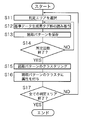
- FIG. 6 is a flowchart showing a procedure for generating reference data.
- a reference data generation tag group is prepared in advance.
- a reference data generation tag group is configured by stacking a plurality of articles with tags attached in the same manner as in operation, and is moved or arranged by the same moving means as in operation.
- the moving means a forklift, a carriage, a conveyor or the like can be used.
- the reference data generation unit 112 of the upper server 100 first selects one determination area from the determination area information stored in the storage unit 105 (step S11). For example, if there are determination areas A1 to Am corresponding to m gates G1 to Gm, the determination area A1 corresponding to the gate G1 is selected as one of them.
- the host server 100 operates all the readers 200 used during normal operation, and then reads the reference data generation tag group under the same conditions (such as movement speed) as during normal operation (Ste S12).
- the gate through which the reference data generation tag group passes is a gate corresponding to the determination area selected in step S11.
- the reading pattern of the tag ID read by the reader 200 is reported to the host server 100.
- the host server 100 temporarily stores the reading pattern reported from the reader 200 in the storage unit 105 for each determination area (step S13). That is, when a reference data generation tag group is passed through a gate, a tag ID reading pattern indicating whether or not each IC tag 10 has been detected by a plurality of antennas ANT installed in the gate is displayed in the gate. Sort and save each.
- step S14 The process of passing the gate corresponding to the selected determination area and reading the reference data generation tag group is repeated a predetermined number of times. Each time it repeats, the reading pattern to be reported from the reader 200 is stored for each tag ID and each determination point.
- the host server 100 determines whether or not the predetermined number of reading processes have been completed after the process of step S13 (step S14). If the predetermined number of reading processes have not been completed (S14: NO), The process returns to step S12.
- step S15 clustering of reading patterns is performed for each determination area.
- various known clustering methods can be used. For example, the following method can be used as a reference similarity calculation method. First, the respective symbol strings of the two reading patterns are compared. If both are “_” or one of them is “_”, 0 is set to the same symbol other than “_” (for example, both “A”, 1 for both “B” and the like, and ⁇ 1 (minus 1) for different symbols, and the obtained integer value is divided by the total number of readings to obtain a temporary similarity. . Then, the similarity is calculated while shifting the reading pattern, and the maximum similarity is obtained as the similarity between the two reading patterns.
- the current determination area means a determination area indicating a gate that has passed the reference data generation tag group.
- the above processing is executed for all determination areas to generate reference data. That is, after the process of step S16, the upper server 100 determines whether or not the reference data has been generated for all the determination areas (step S17), and if there is a determination area in which the reference data is not generated. (S17: NO), the process is returned to step S11, and the process of steps S12 to S16 is executed after changing the target determination area.
- the reference data is generated for all the determination areas (S17: YES)
- the process according to this flowchart is terminated.
- the generated reference data is stored in the storage unit 105 of the upper server 100, transmitted to the reader 200 in charge of each determination area, and stored in the storage unit 204 of the reader 200.
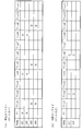
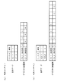
- FIG. 7 is a schematic diagram showing an example of the reference data.
- the example shown in FIG. 7 shows an example of reference data stored in the storage unit 204 of the reader 200 in charge of the determination area A1 and the determination area A2.
- ⁇ C1_1,1> and ⁇ C1_2,1> are stored as reference data for the determination area A1
- ⁇ C2_1,1> and ⁇ C2_2,1> are stored as reference data for the determination area A2.
- C1_1 and C1_2 are clusters read in the determination area A1 when the IC tag 10 is passed in the determination area A1, and attribute 1 is given.
- C2_1 and C2_2 are clusters read in the determination area A2, since C2_2 is a cluster read when the IC tag 10 is passed in the determination area A1, the attribute 0 is given. Since C2_1 is a cluster read when the IC tag 10 is passed through the determination area A2, the attribute 1 is given.
- a typical example of each cluster is also shown for reference.
- the blank column indicates that the IC tag 10 has not been read
- A, B, and C are symbols that identify the antenna ANT.
- C1_1 (typical example) and C1_2 (typical example) indicate reading patterns read by the same reader in the same determination area.
- C1_1 (typical example) represents a reading pattern read by the antenna (antenna ANT1) identified by the symbol A at the first, third, and fifth reading timings.
- C1_2 represents a reading pattern read by the antenna (antenna ANT2) identified by symbol B at the second, fourth, and sixth reading timings.
- the reference data is not limited to the four cases shown in FIG.
- each reader 200 is in charge of similarity determination during operation.
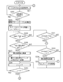
- FIG. 8 is a flowchart showing a processing procedure of similarity determination processing during operation.
- the reading control unit 211 of the reader 200 receives, for example, a reading start instruction from the upper server 100 and sequentially uses the antennas ANT connected to the reader 200 according to the reading control setting stored in the storage unit 204. Repeat the search (event) process in the judgment area.
- the sensor 250 may be used to detect the passage of a person or an article and provide a search processing start trigger. In this case, the reading disclosure instruction input process from the host server 100 may be omitted.
- the reader 200 executes a search process in the same procedure as when generating the reference data, and receives a response from the IC tag 10 by the antenna ANT installed in the determination area (step S21).
- the similarity determination unit 212 of the reader 200 determines whether or not the tag reading report reported from the reading control unit 211 has been received (step S22), and when the tag reading report has not been received (S22: NO) ), The process returns to step S21.
- the similarity determination unit 212 receives a tag reading report from the reading control unit 211 (S22: YES), the following processing is executed.
- the reading control unit 211 of the reader 200 continuously executes the search process using each antenna ANT even during the execution of the following process in the similarity determination unit 212. To do.
- the similarity determination unit 212 increments the value of the number of reports N by 1, and then updates the reading pattern table for that determination area for each tag ID (step S1). S23).
- the reading report from the reading control unit 211 includes the tag ID of the read IC tag 10, identification information for identifying the antenna ANT, and the reading time.
- the similarity determination unit 212 adds a new row to the reading pattern table, the antenna symbol (symbols such as “A” to “D”) and the reading time in the Nth column. And record. If the IC tag 10 has already been read, the corresponding tag ID row already exists, so the antenna symbol and the reading time are recorded in the Nth column of the row.
- “_” representing a blank in the Nth column is recorded in the row of tag IDs that have already been read but the tag ID is not included in the report content.
- “_” representing a blank in the Nth column is recorded in all rows of the reading pattern table.
- a list of tag IDs (Tid1,..., Tidm) described in the reading pattern table is prepared, the value of the counter j is set to 1 (step S24), and the following processing is started. To do.
- the difference (Ne ⁇ N1 + 1) between Ne and the number of reports N1 when the tag is read first is set to Size (Tidj) when the tag is read at the last time. Is compared with the minimum window width W set in step S25. That is, determination processing based on the minimum window width W is performed for Tidj indicating the jth tag ID in the list of tag IDs recorded in the reading pattern table.
- the tag reading pattern of Tidj is extracted by the size (Tidj) and the determination is made. Similarity calculation is performed with the cluster which is the reference data of the area (step S27).
- the target determination area in step S27 is a determination area stored in the storage unit 204 of the reader 200 that executes similarity calculation. For example, in the similarity calculation performed by the reader 200A, the determination area stored in the storage unit 204 of the reader 200A, that is, the determination area A1 configured by the antennas ANT1 and ANT2, and the determination area configured by the antennas ANT3 and ANT4 A2.
- step S27 the similarity between each cluster and the reading pattern is calculated while shifting in the time axis direction, the maximum similarity is calculated for each cluster, and the calculated maximum similarity is associated with the cluster in the similarity table.
- Recording is performed (step S28).
- the similarity table is a tag.
- the matrix has clusters C1 to Cp in the rows of ID (Tid1 to Tidm).
- step S28 the similarity calculated at the intersection designated by the tag ID and the cluster in the similarity table is recorded.
- FIG. 9 is a schematic diagram illustrating an example of a similarity table. Further, when the reference data is a weighted pattern, the similarity can be calculated by adding a weight w of 0 ⁇ w ⁇ 1.
- step S30 After calculating the similarity, the value of the counter j is incremented by 1 (step S29), and it is determined whether j> m is satisfied (step S30). That is, it is determined whether similarity calculation has been performed for all IC tags 10 included in the tag ID list of the reading pattern table. If j ⁇ m, that is, if the tag ID list includes the tag ID of the IC tag 10 for which the similarity is not calculated (S30: NO), the process returns to step S25 to calculate the similarity. Continue. When j> m, that is, when similarity calculation is performed for all IC tags 10 included in the tag ID list (S30: YES), the process returns to step S21 to wait for the next reading report.
- step S25 If Size (Tidj) ⁇ W in step S25 (S25: NO), it is determined that the data necessary for the similarity determination has not yet been collected. Then, in order to determine whether or not the reading of Tidj should be completed, the difference Unread (Tidj) between the latest reading time and the reading time when the tag ID of Tidj was last read is calculated as the reading end elapsed time U. It is determined whether it has not exceeded (step S31).
- the latest reading time means the time when the reader 200 has performed the latest tag reading in the determination area. Since Tidj cannot always be read in the latest reading, a difference in time at which Tidj was last read is acquired.
- step S26 If it is determined in step S26 that the IC tag 10 having the tag ID of Tidj has not been read (S26: NO), it is determined whether Unread (Tidj)> U as in the process of step S31 ( Step S33).
- Unread (Tidj)> U that is, if the tag reading of Tidj does not exceed the reading completion elapsed time U (S33: YES), it is determined that the tag reading of Tidj has been completed.
- the reader 200 performs the similarity report process for the upper server 100 (step S34), deletes the data of Tidj from the read pattern table and the similarity table (S32), and performs the processes after step S29. Execute.
- Unread (Tidj) ⁇ U S33: NO
- the processing after step S29 is executed.
- the similarity report process in step S34 is executed as follows.
- the determination area by the reader 200 is the determination area Ak
- the similarity ⁇ 1 of the cluster C1 having the highest similarity among the clusters having the attribute 1 among the similarities of Tidj from the similarity table of the determination area Ak, the attribute If there is a cluster having 0, the similarity ⁇ 0 of the cluster C0 having the maximum similarity is selected, and report data including Tidj, Ak, ⁇ 1, and ⁇ 0 is generated.
- the reader 200 performs similarity report by transmitting the generated report data to the upper server 100.
- Ak is identification information for identifying the determination area Ak.
- date information indicating the time when the IC tag 10 is detected may be added to the report data.
- the report data may be sent as one message for each tag ID, or records having items of Tidj, Ak, ⁇ 1, and ⁇ 0 are sent as one message in list format for a plurality of tag IDs. May be.
- the upper server 100 When receiving the similarity report from the reader 200, the upper server 100 performs a process of determining a determination area through which the IC tag 10 has passed based on the reference data generated in advance.
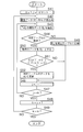
- FIG. 10 is a flowchart showing a processing procedure for determination area determination processing.
- the upper server 100 prepares a determination table in the RAM 103 or the storage unit 105 as a table for recording the determination result.
- report data of a similarity report sent from the reader 200 is recorded.
- the initial value is empty.
- the host server 100 first sets the values of the counters j and k to 1 (step S41). Then, the upper server 100 reads report data R1,..., Rnk of the similarity report for the determination area Ak (step S42).
- nk is the number of IC tags 10 read in the determination area Ak.
- the number of IC tags 10 read in the determination area Ak is nk, there are nk report data for the determination area Ak.
- the upper server 100 extracts the report data Rj in which the tag ID (Tidj) of one IC tag 10 to be determined is recorded from the read report data R1,..., Rnk (step S43). .
- the host server 100 determines whether or not the report data Rj of the IC tag 10 having Tidj as a tag ID already exists in the determination table (step S44). When the report data Rj does not exist in the determination table (S44: NO), the report data is recorded in the determination table (step S45).
- the upper server 100 increments the value of the counter j by 1 (step S46), and determines whether j> nk is satisfied (step S47). If j> nk is not satisfied (S47: NO), the upper server 100 returns the process to step S43. That is, the upper server 100 records each report data in the determination table while changing the value of the counter j from 1 to nk.
- step S47: YES the upper server 100 increments the value of the counter k by 1 (step S48), and determines whether k> m is satisfied (step S49). . If k> m is not satisfied (S49: NO), that is, if there is another determination area that is not compared, the process returns to step S42. When k> m is satisfied (S49: YES), since all the determination areas have been compared, the processing according to this flowchart ends.
- This evaluation function E relates to the similarity ⁇ 1 (or ⁇ 1 ′) as the value of the similarity ⁇ 1 (or ⁇ 1 ′) with the cluster of the read pattern detected by the own gate when passing through the own gate is larger. This indicates that there is a high possibility that the IC tag 10 has passed through the determination area.
- the determination area related to the similarity ⁇ 0 (or ⁇ 0 ′) is set to IC The possibility that the tag 10 has passed is low. That is, in the evaluation function E, the likelihood of similarity report is evaluated based on the magnitude relationship between the similarity ⁇ 1 (or ⁇ 1 ′) and the similarity ⁇ 0 (or ⁇ 0 ′).
- the weighting counts a and b used in the evaluation function E can be changed as necessary and can be omitted.
- the similarity ⁇ 0 can be more strongly evaluated by using a value that satisfies the relationship of a ⁇ b.
- the values of a and b and the format of the evaluation function itself are not limited to this, and appropriate coefficients and evaluation functions can be selected depending on the operation mode.
- the content of the determination table finally obtained indicates a desirable determination result (determination area with high accuracy that each IC tag 10 has passed).
- the higher-level server 100 performs the above-described determination area determination process when a similarity report is received from the reader 200. However, the determination area determination process is performed at predetermined time intervals counted by the higher-level server 100. May be repeated.
- Embodiment 2 the system configuration in which the similarity determination processing is performed on the reader 200 side is also possible, but the configuration may be performed on the host server 100 side including the similarity determination processing.
- the second embodiment a configuration in which the upper server 100 performs a similarity determination process and a determination area determination process based on the detection result of the IC tag 10 acquired via each reader 200 will be described.
- FIG. 11 is a block diagram illustrating functional configurations of the upper server 100 and the reader 200 according to the second embodiment.
- the reader 200 operates autonomously according to the reading control setting, and reads the IC tag 10.
- the reading control unit 211 loads the content of the reading control setting from the storage unit 204, and issues a search (inventory) command for the IC tag 10 to the RF unit 203 corresponding to each antenna ANT according to the described control procedure. It controls to transmit and reads the response from the IC tag 10.
- the read tag ID information is transmitted to the upper server 100 via the communication unit 202.
- the tag data processing unit 113 of the host server 100 compares the tag ID data received from the reader 200 through the communication unit 104 with the reference data stored in advance for each tag ID as in the first embodiment.
- a degree determination unit 115 is provided. Note that the processing content executed by the similarity determination unit 115 is exactly the same as the processing content of the similarity determination unit 212 provided in the reader 200 of the first embodiment.
- the reading area determination unit 114 determines a final reading area from the determination area based on the similarity calculation result between the data such as the tag ID transmitted from the reader 200 and the reference data. As the determination method of the determination area, the method shown in the flowchart of FIG. 10 can be used.
- the configuration of the reader installed at the site can be simplified, and the flexibility of installation at the site is improved.
- the wireless reading of the IC 10 tag may temporarily worsen due to environmental changes or the like, but it is also possible to improve the determination accuracy by ignoring the temporary inability to read the IC tag 10.
- Such a system is effective when there is only one antenna in each determination area.
- the strength of the antenna output affects the reading of the tag, it is possible to search the tag by intentionally switching the antenna output repeatedly in two stages by providing the reader with an antenna output control unit. . By repeatedly reading the tag with an output level having an appropriate height difference, it is possible to more accurately distinguish two moving objects moving in the determination areas having different distances from the antenna.
Landscapes
- Engineering & Computer Science (AREA)
- Health & Medical Sciences (AREA)
- Toxicology (AREA)
- Physics & Mathematics (AREA)
- Computer Networks & Wireless Communication (AREA)
- Electromagnetism (AREA)
- General Health & Medical Sciences (AREA)
- Artificial Intelligence (AREA)
- Computer Vision & Pattern Recognition (AREA)
- General Physics & Mathematics (AREA)
- Theoretical Computer Science (AREA)
- Management, Administration, Business Operations System, And Electronic Commerce (AREA)
Abstract
Description
また、RFIDの周波数帯としてUHF帯(860~960MHz)を用いた場合、パッシブ型でも読取範囲が他の周波数帯に比較して広く、一度に複数のタグを読み取ることができる。
このため、例えば物流分野において、多数の物品に貼られた複数のタグを一括で読み取り、検品を行うことなどが可能となる。
実施の形態1.
図1は実施の形態1に係るICタグ読取システムの全体構成を示す模式図である。実施の形態1に係るICタグ読取システムは、上位サーバ100、リーダ200A,200B、アンテナANT1~ANT8、ICタグ10を含む。
なお、以下の説明において、リーダ200A,200Bを互いに区別して説明する必要がない場合には、リーダ200と記載することとし、アンテナANT1~ANT8を互いに区別して説明する必要がない場合には、アンテナANTと記載することとする。
上位サーバ100は、リーダ200から送信されるデータを、予め与えられたプログラムに従って処理する。
なお、上記の動作は、電池を内蔵しないパッシブ型のICタグに関するものであるが、電池を内蔵するアクティブ型のICタグを利用することも可能である。
また、本実施の形態では、8枚のアンテナANT1~ANT8を2台のリーダ200A,200Bで管理する構成としたが、アンテナの枚数、リーダの台数は、適宜設定し得るものである。
例えば、配送センタなどにおいて、配送先の異なるトラックに物品を積み込むために、複数のゲートG1,G2が設置され、各ゲートG1,G2にてICタグ10を読み取るために、アンテナANT1~ANT4が設置される。ゲートG1,G2の識別情報は、判定エリアA1,A2としてリーダ200A及び上位サーバ100により管理される。
なお、図2に示していない判定エリアA3,A4についても同様である。
制御部101は、所定のタイミングに従って、ROM102又は記憶部105に格納されているコンピュータプログラムを適宜RAM103上に読み出して実行するとともに、上述したハードウェア各部の動作を制御する。
RF部203には、ICタグ10からデータを取得するアンテナANTが接続される。本実施の形態では、リーダ200AのRF部203にアンテナANT1~ANT4が接続され、リーダ200BのRF部203にアンテナANT5~ANT8が接続される。
これにより、リーダ200は、ICタグ10のタグIDを識別することができ、リーダ200とICタグ10との間でデータの送受信が可能になる。
リーダ200及び上位サーバ100は、このタグID毎の繰り返し受信した時系列のパターンを用いて、不要タグ読取フィルタリング処理を行う。
また、アンテナ出力を2段階に変化させる場合、出力が大きいときには大文字で「A」のように表記し、出力が小さいときには小文字で「a」のように表記してもよい。
全ての判定エリアについて基準データを生成した場合(S17:YES)、本フローチャートによる処理を終了する。生成された基準データは、上位サーバ100の記憶部105に記憶されると共に、各判定エリアを担当するリーダ200に送信され、リーダ200の記憶部204に記憶される。
C1_1(典型例)は、1回目、3回目、5回目の読取タイミングにて、記号Aで識別されるアンテナ(アンテナANT1)により読み取った読取パターンを表している。また、C1_2(典型例)は、2回目、4回目、6回目の読取タイミングにて、記号Bで識別されるアンテナ(アンテナANT2)により読み取った読取パターンを表している。C2_1(典型例)及びC2_2(典型例)についても同様である。
なお、基準データは、図7に示した4件に限定されるものではない。
なお、センサ250を用いて人や物品の通過を検知し、探索処理の開始トリガを与える構成としてもよい。この場合、上位サーバ100からの読取開示指示の入力処理を省略してもよい。
また、類似度判定部212は、タグ読取報告の回数を表すNというパラメータを使用し、初期状態ではN=0とし、報告を受信する都度、Nの値を1ずつインクリメントする。
更に、類似度判定部212が使用する固定のパラメータとして、判定用最小窓幅W、読取終了経過時間Uが予め記憶されているものとする。
読取制御部211からの読取報告には、読み取ったICタグ10のタグID、アンテナANTを識別する識別情報、読取時刻が含まれる。新規に読み取ったICタグ10である場合、類似度判定部212は、読取パターンテーブルに新規の行を追加し、N列目にアンテナ記号(「A」~「D」等の記号)と読取時刻とを記録する。既に読まれているICタグ10である場合には、対応するタグIDの行が既に存在するので、その行のN列目にアンテナ記号と読取時刻とを記録する。
また、既に読まれているが、報告内容にタグIDが含まれていないタグIDの行にはN列目に空欄を表す「_」を記録する。読取報告の内容が空の場合、すなわち、全くタグIDが読めなかった場合は、読取パターンテーブルの全ての行において、N列目に空欄を表す「_」を記録する。
このように、1台のリーダ200に複数の判定エリアが設定されている場合には、設定されている複数の判定エリアの基準データとの類似度計算を実行する。なお、1台のリーダ200において複数の判定エリアが設定されていることは、1台のリーダ200に接続されたアンテナANTが複数のゲートに設置されていることを意味する。
また、基準データが重み付きパターンである場合には、0≦w≦1の重みwを付加して類似度を計算することもできる。
j>mである場合、すなわち、タグIDリストに含まれる全てのICタグ10について類似度計算を行った場合(S30:YES)、処理をステップS21へ戻して、次の読取報告を待つ。
そして、Tidjの読み取りが終了と判断すべきか否かを判定するために、最新の読取時刻とTidjのタグIDを最後に読み取った読取時刻との差分Unread(Tidj)が、読取終了経過時間Uを越えていないか否かを判定する(ステップS31)。ここで、最新の読取時刻とは、リーダ200がその判定エリアにおいて最新のタグ読み取りを実施した時刻を意味する。最新の読み取りにおいて、Tidjが読み取れるとは限らないため、最後にTidjが読み取れた時刻の差分を取得する。
Tidjのデータを削除した場合、又はUnread(Tidj)≦Uである場合(S31:NO)、ステップS29以降の処理を実行する。
Unread(Tidj)≦Uである場合には(S33:NO)、ステップS29以降の処理を実行する。
なお、報告データに、ICタグ10を検出した時刻などを示す日時情報を付加してもよい。報告データは、1つのタグID毎に1件の電文で送信しても良いし、複数のタグIDについて、Tidj,Ak,σ1,σ0の項目を有するレコードをリスト形式で1件の電文として送信してもよい。
上位サーバ100は、TidjをタグIDとして有するICタグ10の報告データRjが判定テーブルに既に存在するか否かを判断する(ステップS44)。報告データRjが判定テーブルに存在しない場合(S44:NO)、その報告データを判定テーブルに記録する(ステップS45)。
k>mを満たす場合には(S49:YES)、全ての判定エリアについて比較を行ったため、本フローチャートによる処理を終了する。
すなわち、評価関数Eでは、類似度σ1(又はσ1’)と類似度σ0(又はσ0’)との大小関係により、類似度報告の確からしさが評価される。
一方、ステップS51において、E(σ1’,σ0’)<E(σ1,σ0)を満たすと判断した場合(S51:YES)、判定テーブルのデータをRj=(Tidj,Ak,σ1,σ0)に更新する(ステップS52)。すなわち、ステップS43で抽出したRj及び判定テーブルに記録されているRjのそれぞれについて、評価関数Eの値を計算した後、それらの評価関数Eの値を比較し、評価関数Eの値が大きな類似度報告を採用する。
ステップS52の処理の後、上位サーバ100は、ステップS47以降の処理を実行する。
実施の形態1では、類似度判定処理までをリーダ200側で行うシステム構成としたが、類似度判定処理も含めて上位サーバ100側で行う構成としてもよい。
実施の形態2では、各リーダ200を介して取得するICタグ10の検出結果を基に、上位サーバ100が類似度判定処理、判定エリアの決定処理を行う構成について説明する。
本実施の形態では、読み取ったタグIDの情報を、通信部202を介して上位サーバ100へ送信する。
読取エリア判定部114は、リーダ200から送信されたタグID等のデータと基準データとの類似度計算結果を基に、最終的な読取エリアを判定エリアの中から決定する。判定エリアの決定手法は、図10のフローチャートに示した手法を用いることができる。
このようなシステムは、各判定エリアにアンテナが一枚しかないような場合に有効である。
適切な高低差を持つ出力レベルを繰返してタグ読取を行なうことにより、アンテナからの距離が異なる判定エリアを移動する2つの移動物体をより精度良く区別することができる。
100 上位サーバ(判定装置、第2判定装置)
101 制御部
102 ROM
103 RAM
104 通信部
105 記憶部
106 表示部
107 操作部
200 リーダ(第1判定装置)
201 制御部
202 通信部
203 RF部
204 記憶部
206 外部入出力部
250 センサ
ANT アンテナ
Claims (8)
- 第1領域又は該第1領域と異なる第2領域を通過した被検出体の検出状況に応じたデータを時系列的に出力する検出器からデータを取得するデータ取得部、
被検出体が前記第1領域を通過した際に前記第1領域で前記検出器が出力すべきデータを示す第1基準データと、前記被検出体が前記第2領域を通過した際に前記第1領域で前記検出器が出力すべきデータを示す第2基準データとを記憶する記憶部、
前記データ取得部にて取得したデータと前記記憶部に記憶してある第1及び第2基準データとの類似度を判定する類似度判定部、及び
該類似度判定部による判定結果に基づき、被検出体が前記第1領域を通過したか否かを判定する通過領域判定部
を備えることを特徴とする判定装置。 - 前記判定結果に基づき、被検出体が前記第1領域を通過した確度を算出する算出部を備え、
該算出部は、前記データと前記第1基準データとの類似度が高い程、前記確度を高く、前記データと前記第2基準データとの類似度が高い程、前記確度を低く算出するようにしてあり、
前記通過領域判定部は、前記算出部が算出した確度に従って判定を行うようにしてあることを特徴とする請求項1に記載の判定装置。 - 前記通過領域判定部は、前記データと前記第1基準データとの類似度及び前記データと前記第2基準データとの類似度から算出された確度が、前記データと前記第2領域において同様に記憶された前記第1及び第2基準データとの類似度から算出された確度より高い場合、被検出体は前記第1領域を通過したと判定するようにしてあることを特徴とする請求項1に記載の判定装置。
- 第1領域又は該第1領域と異なる第2領域を通過する被検出体の検出状況に応じたデータを時系列的に出力する検出器、及び
該検出器が出力するデータを取得するデータ取得部と、
被検出体が前記第1領域を通過した際に前記第1領域で前記検出器が出力すべきデータを示す第1基準データと、前記被検出体が前記第2領域を通過した際に前記第1領域で前記検出器が出力すべきデータを示す第2基準データとを記憶する記憶部と、
前記データ取得部にて取得したデータと前記記憶部に記憶してある第1及び第2基準データとの類似度を判定する類似度判定部と、
該類似度判定部による判定結果に基づき、被検出体が前記第1領域を通過したか否かを判定する通過領域判定部とを備える判定装置
を含むことを特徴とする判定システム。 - 前記判定結果に基づき、被検出体が前記第1領域を通過した確度を算出する算出部を備え、
該算出部は、前記データと前記第1基準データとの類似度が高い程、前記確度を高く、前記データと前記第2基準データとの類似度が高い程、前記確度を低く算出するようにしてあり、
前記通過領域判定部は、前記算出部が算出した確度に従って判定を行うようにしてあることを特徴とする請求項4に記載の判定システム。 - 前記通過領域判定部は、前記データと前記第1基準データとの類似度及び前記データと前記第2基準データとの類似度から算出された確度が、前記データと前記第2領域において同様に記憶された前記第1及び第2基準データとの類似度から算出された確度より高い場合、被検出体は前記第1領域を通過したと判定するようにしてあることを特徴とする請求項4に記載の判定システム。
- 第1領域又は該第1領域と異なる第2領域を通過する被検出体の検出状況に応じたデータを時系列的に出力する検出器から前記データを取得し、
取得したデータと被検出体が前記第1領域を通過した際に前記検出器が出力すべきデータを示す第1基準データとの類似度、及び前記データと前記被検出体が前記第2領域を通過した際に前記検出器が出力すべきデータを示す第2基準データとの類似度を算出し、
前記データと前記第1基準データとの類似度が、前記データと前記第2基準データとの類似度よりも高い場合、前記被検出体が前記第1領域を通過したと判定する
ことを特徴とする判定方法。 - コンピュータに、被検出体の検出状況に応じたデータを時系列的に出力する検出器から取得したデータと被検出体が第1領域を通過した際に前記検出器が出力すべきデータを示す第1基準データとの類似度、及び前記データと前記被検出体が前記第1領域と異なる第2領域を通過した際に前記検出器が出力すべきデータを示す第2基準データとの類似度を判定させるステップと、
コンピュータに、判定させた結果に基づき、被検出体が前記第1領域を通過したか否かを判定させるステップと
を実行させることを特徴とするコンピュータプログラム。
Priority Applications (4)
| Application Number | Priority Date | Filing Date | Title |
|---|---|---|---|
| JP2012505381A JP5273291B2 (ja) | 2010-03-17 | 2010-03-17 | 判定装置、判定システム、判定方法及びコンピュータプログラム |
| CN201080065343.6A CN102792318B (zh) | 2010-03-17 | 2010-03-17 | 判定装置、判定系统以及判定方法 |
| PCT/JP2010/054597 WO2011114474A1 (ja) | 2010-03-17 | 2010-03-17 | 判定装置、判定システム、判定方法及びコンピュータプログラム |
| US13/614,271 US9405946B2 (en) | 2010-03-17 | 2012-09-13 | Judgment apparatus, judgment system, and judgment method |
Applications Claiming Priority (1)
| Application Number | Priority Date | Filing Date | Title |
|---|---|---|---|
| PCT/JP2010/054597 WO2011114474A1 (ja) | 2010-03-17 | 2010-03-17 | 判定装置、判定システム、判定方法及びコンピュータプログラム |
Related Child Applications (1)
| Application Number | Title | Priority Date | Filing Date |
|---|---|---|---|
| US13/614,271 Continuation US9405946B2 (en) | 2010-03-17 | 2012-09-13 | Judgment apparatus, judgment system, and judgment method |
Publications (1)
| Publication Number | Publication Date |
|---|---|
| WO2011114474A1 true WO2011114474A1 (ja) | 2011-09-22 |
Family
ID=44648603
Family Applications (1)
| Application Number | Title | Priority Date | Filing Date |
|---|---|---|---|
| PCT/JP2010/054597 Ceased WO2011114474A1 (ja) | 2010-03-17 | 2010-03-17 | 判定装置、判定システム、判定方法及びコンピュータプログラム |
Country Status (4)
| Country | Link |
|---|---|
| US (1) | US9405946B2 (ja) |
| JP (1) | JP5273291B2 (ja) |
| CN (1) | CN102792318B (ja) |
| WO (1) | WO2011114474A1 (ja) |
Cited By (3)
| Publication number | Priority date | Publication date | Assignee | Title |
|---|---|---|---|---|
| US20130169417A1 (en) * | 2011-12-28 | 2013-07-04 | Fujitsu Limited | Rfid tag reader, rfid tag reading system, method for performing rfid tag reading process and computer-readable recording medium |
| JP2022018945A (ja) * | 2020-07-16 | 2022-01-27 | 東芝テック株式会社 | 制御装置、及び画像形成装置 |
| WO2025088707A1 (ja) * | 2023-10-24 | 2025-05-01 | 日本電気株式会社 | 物品特定装置、物品特定方法および非一時的なコンピュータ可読記録媒体 |
Families Citing this family (5)
| Publication number | Priority date | Publication date | Assignee | Title |
|---|---|---|---|---|
| US9436857B2 (en) | 2012-01-16 | 2016-09-06 | Hand Held Products, Inc. | Encoded information reading system including RFID reading device having multiple antennas |
| DE102015208667A1 (de) * | 2015-05-11 | 2016-11-17 | Siemens Aktiengesellschaft | Detektionsvorrichtung und Verfahren zum Detektieren von einer Mehrzahl von RFID-Tags |
| JP6911429B2 (ja) * | 2017-03-22 | 2021-07-28 | 株式会社デンソーウェーブ | 無線タグ通過判断装置 |
| EP3462260A1 (de) * | 2017-09-29 | 2019-04-03 | Siemens Aktiengesellschaft | Verfahren und anordnung zur überwachung des zustands einer produktionseinrichtung |
| CN109784434B (zh) * | 2018-12-18 | 2021-06-22 | 虫极科技(北京)有限公司 | 一种智能货柜及其rfid标签查询、盘点方法和系统 |
Citations (3)
| Publication number | Priority date | Publication date | Assignee | Title |
|---|---|---|---|---|
| JP2009259232A (ja) * | 2008-03-26 | 2009-11-05 | Fujitsu Ltd | 読取装置、コンピュータプログラム及び読取システム |
| JP2009276939A (ja) * | 2008-05-13 | 2009-11-26 | Nec Corp | 無線idタグシステム |
| JP2009284285A (ja) * | 2008-05-23 | 2009-12-03 | Nec Corp | Icタグ一括読み取りゲート、及び電界漏洩防止方法 |
Family Cites Families (6)
| Publication number | Priority date | Publication date | Assignee | Title |
|---|---|---|---|---|
| JP2002092114A (ja) | 2000-09-20 | 2002-03-29 | Sharp Corp | 物品管理システム |
| JP4412972B2 (ja) | 2003-10-31 | 2010-02-10 | 株式会社小松製作所 | 車両接近通報システム |
| JP2005275960A (ja) | 2004-03-25 | 2005-10-06 | Brother Ind Ltd | 対象物特定装置、対象物特定システム及び人気投票システム |
| WO2006011194A1 (ja) | 2004-07-27 | 2006-02-02 | Fujitsu Limited | 無線質問器システムおよびその無線通信方法 |
| JP2008142248A (ja) | 2006-12-08 | 2008-06-26 | Seiko Precision Inc | 競技用計時システム、無線機器、および、タイム送信方法 |
| JP2010123086A (ja) | 2008-11-21 | 2010-06-03 | Fujitsu Ltd | Icタグ読取適否判別方法、icタグ読取適否判別装置、およびコンピュータプログラム |
-
2010
- 2010-03-17 WO PCT/JP2010/054597 patent/WO2011114474A1/ja not_active Ceased
- 2010-03-17 JP JP2012505381A patent/JP5273291B2/ja not_active Expired - Fee Related
- 2010-03-17 CN CN201080065343.6A patent/CN102792318B/zh not_active Expired - Fee Related
-
2012
- 2012-09-13 US US13/614,271 patent/US9405946B2/en not_active Expired - Fee Related
Patent Citations (3)
| Publication number | Priority date | Publication date | Assignee | Title |
|---|---|---|---|---|
| JP2009259232A (ja) * | 2008-03-26 | 2009-11-05 | Fujitsu Ltd | 読取装置、コンピュータプログラム及び読取システム |
| JP2009276939A (ja) * | 2008-05-13 | 2009-11-26 | Nec Corp | 無線idタグシステム |
| JP2009284285A (ja) * | 2008-05-23 | 2009-12-03 | Nec Corp | Icタグ一括読み取りゲート、及び電界漏洩防止方法 |
Cited By (5)
| Publication number | Priority date | Publication date | Assignee | Title |
|---|---|---|---|---|
| US20130169417A1 (en) * | 2011-12-28 | 2013-07-04 | Fujitsu Limited | Rfid tag reader, rfid tag reading system, method for performing rfid tag reading process and computer-readable recording medium |
| US9129165B2 (en) * | 2011-12-28 | 2015-09-08 | Fujitsu Limited | RFID tag reader, RFID tag reading system, method for performing RFID tag reading process and computer-readable recording medium |
| JP2022018945A (ja) * | 2020-07-16 | 2022-01-27 | 東芝テック株式会社 | 制御装置、及び画像形成装置 |
| JP7458260B2 (ja) | 2020-07-16 | 2024-03-29 | 東芝テック株式会社 | 制御装置、及び画像形成装置 |
| WO2025088707A1 (ja) * | 2023-10-24 | 2025-05-01 | 日本電気株式会社 | 物品特定装置、物品特定方法および非一時的なコンピュータ可読記録媒体 |
Also Published As
| Publication number | Publication date |
|---|---|
| US20130060725A1 (en) | 2013-03-07 |
| US9405946B2 (en) | 2016-08-02 |
| CN102792318A (zh) | 2012-11-21 |
| JP5273291B2 (ja) | 2013-08-28 |
| CN102792318B (zh) | 2015-07-29 |
| JPWO2011114474A1 (ja) | 2013-06-27 |
Similar Documents
| Publication | Publication Date | Title |
|---|---|---|
| JP5273291B2 (ja) | 判定装置、判定システム、判定方法及びコンピュータプログラム | |
| US20130009751A1 (en) | Method for updating firmware and communication unit | |
| JP5490016B2 (ja) | 所与の領域内に含まれるrfidタグ付き商品を決定するためのシステム、方法、およびコンピュータ・プログラム(システムおよび方法) | |
| US20060197652A1 (en) | Method and system for proximity tracking-based adaptive power control of radio frequency identification (RFID) interrogators | |
| US9129165B2 (en) | RFID tag reader, RFID tag reading system, method for performing RFID tag reading process and computer-readable recording medium | |
| US20190333245A1 (en) | Location tracking | |
| US20080030335A1 (en) | TAG extracting device, TAG extracting method, and computer product | |
| US20080143532A1 (en) | Context-driven RFID tag and system content | |
| CN102004944A (zh) | 使用自动化物件跟踪实现与陈列图相符 | |
| JP5343646B2 (ja) | 読取装置、コンピュータプログラム及び読取システム | |
| CN102855457A (zh) | 一种基于智能预测的门形rfid多天线部署系统及方法 | |
| Jo et al. | Mobile RFID tag detection influence factors and prediction of tag detectability | |
| Chaves et al. | A survey on organic smart labels for the Internet-of-Things | |
| WO2012098853A1 (ja) | 動線検出処理データ分散システム、動線検出処理データ分散方法およびプログラム | |
| US20250126440A1 (en) | Locationing System that Utilizes Read Data of a Reader of a Device | |
| US20070215702A1 (en) | Tag access control system, tag access control method and tag access control program | |
| JP2010123086A (ja) | Icタグ読取適否判別方法、icタグ読取適否判別装置、およびコンピュータプログラム | |
| JP2013216481A (ja) | 部材搬送管理システム及び部材搬送管理方法 | |
| CN106997479A (zh) | 一种基于rfid技术的库存管理系统 | |
| CN101169822A (zh) | 通信方法、通信系统、访问控制装置以及计算机程序产品 | |
| CN102201069A (zh) | 判定装置、判定系统、判定方法以及记录介质 | |
| Rao et al. | On the “Invisible Inventory Conundrum” in RFID‐Equipped Supply Chains: A Data Science Approach to Assessing Tag Performance | |
| JP4086000B2 (ja) | Rfidリーダ、在庫管理システムおよび在庫管理方法 | |
| WO2021046259A1 (en) | Methods and systems for classifying tag status in a retail environment | |
| JP5196007B2 (ja) | 目的icタグ判別システム、目的icタグ判別装置、目的icタグ判別方法、およびコンピュータプログラム |
Legal Events
| Date | Code | Title | Description |
|---|---|---|---|
| WWE | Wipo information: entry into national phase |
Ref document number: 201080065343.6 Country of ref document: CN |
|
| 121 | Ep: the epo has been informed by wipo that ep was designated in this application |
Ref document number: 10847889 Country of ref document: EP Kind code of ref document: A1 |
|
| WWE | Wipo information: entry into national phase |
Ref document number: 2012505381 Country of ref document: JP |
|
| NENP | Non-entry into the national phase |
Ref country code: DE |
|
| 122 | Ep: pct application non-entry in european phase |
Ref document number: 10847889 Country of ref document: EP Kind code of ref document: A1 |