WO2011111185A1 - 非水電解質および金属空気電池 - Google Patents
非水電解質および金属空気電池 Download PDFInfo
- Publication number
- WO2011111185A1 WO2011111185A1 PCT/JP2010/053995 JP2010053995W WO2011111185A1 WO 2011111185 A1 WO2011111185 A1 WO 2011111185A1 JP 2010053995 W JP2010053995 W JP 2010053995W WO 2011111185 A1 WO2011111185 A1 WO 2011111185A1
- Authority
- WO
- WIPO (PCT)
- Prior art keywords
- negative electrode
- metal
- electrode layer
- air
- aqueous electrolyte
- Prior art date
- Legal status (The legal status is an assumption and is not a legal conclusion. Google has not performed a legal analysis and makes no representation as to the accuracy of the status listed.)
- Ceased
Links
Images

Classifications
-
- H—ELECTRICITY
- H01—ELECTRIC ELEMENTS
- H01M—PROCESSES OR MEANS, e.g. BATTERIES, FOR THE DIRECT CONVERSION OF CHEMICAL ENERGY INTO ELECTRICAL ENERGY
- H01M12/00—Hybrid cells; Manufacture thereof
- H01M12/04—Hybrid cells; Manufacture thereof composed of a half-cell of the fuel-cell type and of a half-cell of the primary-cell type
- H01M12/06—Hybrid cells; Manufacture thereof composed of a half-cell of the fuel-cell type and of a half-cell of the primary-cell type with one metallic and one gaseous electrode
-
- H—ELECTRICITY
- H01—ELECTRIC ELEMENTS
- H01M—PROCESSES OR MEANS, e.g. BATTERIES, FOR THE DIRECT CONVERSION OF CHEMICAL ENERGY INTO ELECTRICAL ENERGY
- H01M10/00—Secondary cells; Manufacture thereof
- H01M10/05—Accumulators with non-aqueous electrolyte
- H01M10/056—Accumulators with non-aqueous electrolyte characterised by the materials used as electrolytes, e.g. mixed inorganic/organic electrolytes
- H01M10/0564—Accumulators with non-aqueous electrolyte characterised by the materials used as electrolytes, e.g. mixed inorganic/organic electrolytes the electrolyte being constituted of organic materials only
- H01M10/0566—Liquid materials
-
- H—ELECTRICITY
- H01—ELECTRIC ELEMENTS
- H01M—PROCESSES OR MEANS, e.g. BATTERIES, FOR THE DIRECT CONVERSION OF CHEMICAL ENERGY INTO ELECTRICAL ENERGY
- H01M10/00—Secondary cells; Manufacture thereof
- H01M10/05—Accumulators with non-aqueous electrolyte
- H01M10/056—Accumulators with non-aqueous electrolyte characterised by the materials used as electrolytes, e.g. mixed inorganic/organic electrolytes
- H01M10/0564—Accumulators with non-aqueous electrolyte characterised by the materials used as electrolytes, e.g. mixed inorganic/organic electrolytes the electrolyte being constituted of organic materials only
- H01M10/0566—Liquid materials
- H01M10/0567—Liquid materials characterised by the additives
-
- H—ELECTRICITY
- H01—ELECTRIC ELEMENTS
- H01M—PROCESSES OR MEANS, e.g. BATTERIES, FOR THE DIRECT CONVERSION OF CHEMICAL ENERGY INTO ELECTRICAL ENERGY
- H01M10/00—Secondary cells; Manufacture thereof
- H01M10/42—Methods or arrangements for servicing or maintenance of secondary cells or secondary half-cells
- H01M10/4235—Safety or regulating additives or arrangements in electrodes, separators or electrolyte
-
- H—ELECTRICITY
- H01—ELECTRIC ELEMENTS
- H01M—PROCESSES OR MEANS, e.g. BATTERIES, FOR THE DIRECT CONVERSION OF CHEMICAL ENERGY INTO ELECTRICAL ENERGY
- H01M12/00—Hybrid cells; Manufacture thereof
- H01M12/08—Hybrid cells; Manufacture thereof composed of a half-cell of a fuel-cell type and a half-cell of the secondary-cell type
-
- H—ELECTRICITY
- H01—ELECTRIC ELEMENTS
- H01M—PROCESSES OR MEANS, e.g. BATTERIES, FOR THE DIRECT CONVERSION OF CHEMICAL ENERGY INTO ELECTRICAL ENERGY
- H01M10/00—Secondary cells; Manufacture thereof
- H01M10/05—Accumulators with non-aqueous electrolyte
- H01M10/056—Accumulators with non-aqueous electrolyte characterised by the materials used as electrolytes, e.g. mixed inorganic/organic electrolytes
- H01M10/0564—Accumulators with non-aqueous electrolyte characterised by the materials used as electrolytes, e.g. mixed inorganic/organic electrolytes the electrolyte being constituted of organic materials only
- H01M10/0566—Liquid materials
- H01M10/0569—Liquid materials characterised by the solvents
-
- H—ELECTRICITY
- H01—ELECTRIC ELEMENTS
- H01M—PROCESSES OR MEANS, e.g. BATTERIES, FOR THE DIRECT CONVERSION OF CHEMICAL ENERGY INTO ELECTRICAL ENERGY
- H01M2300/00—Electrolytes
- H01M2300/0017—Non-aqueous electrolytes
- H01M2300/0025—Organic electrolyte
-
- H—ELECTRICITY
- H01—ELECTRIC ELEMENTS
- H01M—PROCESSES OR MEANS, e.g. BATTERIES, FOR THE DIRECT CONVERSION OF CHEMICAL ENERGY INTO ELECTRICAL ENERGY
- H01M4/00—Electrodes
- H01M4/02—Electrodes composed of, or comprising, active material
- H01M4/36—Selection of substances as active materials, active masses, active liquids
- H01M4/38—Selection of substances as active materials, active masses, active liquids of elements or alloys
- H01M4/40—Alloys based on alkali metals
- H01M4/405—Alloys based on lithium
-
- H—ELECTRICITY
- H01—ELECTRIC ELEMENTS
- H01M—PROCESSES OR MEANS, e.g. BATTERIES, FOR THE DIRECT CONVERSION OF CHEMICAL ENERGY INTO ELECTRICAL ENERGY
- H01M4/00—Electrodes
- H01M4/02—Electrodes composed of, or comprising, active material
- H01M4/36—Selection of substances as active materials, active masses, active liquids
- H01M4/48—Selection of substances as active materials, active masses, active liquids of inorganic oxides or hydroxides
- H01M4/485—Selection of substances as active materials, active masses, active liquids of inorganic oxides or hydroxides of mixed oxides or hydroxides for inserting or intercalating light metals, e.g. LiTi2O4 or LiTi2OxFy
-
- H—ELECTRICITY
- H01—ELECTRIC ELEMENTS
- H01M—PROCESSES OR MEANS, e.g. BATTERIES, FOR THE DIRECT CONVERSION OF CHEMICAL ENERGY INTO ELECTRICAL ENERGY
- H01M4/00—Electrodes
- H01M4/02—Electrodes composed of, or comprising, active material
- H01M4/36—Selection of substances as active materials, active masses, active liquids
- H01M4/58—Selection of substances as active materials, active masses, active liquids of inorganic compounds other than oxides or hydroxides, e.g. sulfides, selenides, tellurides, halogenides or LiCoFy; of polyanionic structures, e.g. phosphates, silicates or borates
-
- Y—GENERAL TAGGING OF NEW TECHNOLOGICAL DEVELOPMENTS; GENERAL TAGGING OF CROSS-SECTIONAL TECHNOLOGIES SPANNING OVER SEVERAL SECTIONS OF THE IPC; TECHNICAL SUBJECTS COVERED BY FORMER USPC CROSS-REFERENCE ART COLLECTIONS [XRACs] AND DIGESTS
- Y02—TECHNOLOGIES OR APPLICATIONS FOR MITIGATION OR ADAPTATION AGAINST CLIMATE CHANGE
- Y02E—REDUCTION OF GREENHOUSE GAS [GHG] EMISSIONS, RELATED TO ENERGY GENERATION, TRANSMISSION OR DISTRIBUTION
- Y02E60/00—Enabling technologies; Technologies with a potential or indirect contribution to GHG emissions mitigation
- Y02E60/10—Energy storage using batteries
Definitions
- the present invention relates to a nonaqueous electrolyte having good radical resistance.
- the metal-air battery is a non-aqueous battery using air (oxygen) as a positive electrode active material, and has advantages such as high energy density, easy miniaturization and weight reduction. For this reason, it has attracted attention as a high-capacity battery that exceeds the lithium batteries that are currently widely used.
- Such a metal-air battery includes, for example, an air electrode layer having a conductive material (for example, carbon black), a catalyst (for example, manganese dioxide), and a binder (for example, polyvinylidene fluoride), and collecting current from the air electrode layer.
- An air electrode current collector to be performed a negative electrode layer containing a negative electrode active material (for example, metal Li), a negative electrode current collector for current collection of the negative electrode layer, and a non-aqueous electrolyte (for example, a non-aqueous electrolyte solution) .
- a conductive material for example, carbon black
- a catalyst for example, manganese dioxide
- a binder for example, polyvinylidene fluoride
- a metal salt for example, LiPF 6
- an organic solvent such as ethylene carbonate (EC), propylene carbonate (PC), dimethyl carbonate (DMC), and diethyl carbonate (DEC).
- EC ethylene carbonate
- PC propylene carbonate
- DMC dimethyl carbonate
- DEC diethyl carbonate
- Patent Document 1 discloses the use of a room temperature molten salt (ionic liquid) having a specific structure for the nonaqueous electrolyte of a nonaqueous electrolyte air battery. This technique is intended to improve the discharge capacity in a high temperature environment by using a highly non-volatile room temperature molten salt.
- ionic liquid When an ionic liquid is used for the non-aqueous electrolyte of a metal-air battery, it is presumed that the ionic liquid deteriorates (decomposes) due to radicals (for example, oxygen radicals) generated by an electrode reaction, although it is preferable in terms of nonvolatility.
- radicals for example, oxygen radicals
- the ionic liquid is decomposed by generation of radicals derived from oxygen mixed during the manufacturing process.
- the present invention has been made in view of the above circumstances, and its main object is to provide a non-aqueous electrolyte having good radical resistance.
- a nonaqueous electrolyte containing an ionic liquid having a cation part and an anion part, an organic solvent, and a metal salt, the cation part of the ionic liquid, and the above
- the organic solvent provides a nonaqueous electrolyte characterized in that the maximum charge calculated by the first principle calculation is 0.3 or less.
- the cation part of the ionic liquid and the maximum charge of the organic solvent are in a specific range, a non-aqueous electrolyte with good radical resistance can be obtained. Thereby, deterioration (decomposition) of the nonaqueous electrolyte due to radicals can be suppressed.
- the viscosity is preferably 100 mPa ⁇ s or less. This is because the operation of the battery in a high current density region is facilitated.
- the ionic liquid is preferably N-methyl-N-propylpiperidinium bistrifluoromethanesulfonylimide. It is because it is excellent in radical resistance.
- the organic solvent is preferably at least one of acetonitrile and dimethoxyethane. It is because it is excellent in radical resistance.
- the ratio of the organic solvent to the total of the ionic liquid and the organic solvent is preferably in the range of 1% by volume to 50% by volume. It is because it can be set as a low-viscosity nonaqueous electrolyte, maintaining desired nonvolatility if it is in the said range.
- the nonaqueous electrolyte is preferably used for a metal-air battery. This is because oxygen radicals are generated by the electrode reaction during charge / discharge, the non-aqueous electrolyte is easily deteriorated, and the effects of the present invention are easily exhibited.
- an air electrode layer containing a conductive material an air electrode having an air electrode current collector for collecting the air electrode layer, a negative electrode layer containing a negative electrode active material, and the negative electrode
- a negative electrode having a negative electrode current collector for collecting current of the layer and a nonaqueous electrolyte for conducting metal ions between the air electrode layer and the negative electrode layer, wherein the nonaqueous electrolyte is the nonaqueous electrolyte described above.
- a metal-air battery characterized by being an electrolyte is provided.
- the present invention by using the non-aqueous electrolyte described above, deterioration due to radicals can be suppressed, and a metal-air battery excellent in durability can be obtained.
- FIG. 6 is a measurement result of the viscosity of the mixed solvent obtained in Production Examples 1 to 5 and the comparative sample obtained in Comparative Production Examples 1 and 2.
- FIG. 6 is a measurement result of the viscosity of the mixed solvent obtained in Production Examples 1 to 5 and the comparative sample obtained in Comparative Production Examples 1 and 2.
- the nonaqueous electrolyte of the present invention is a nonaqueous electrolyte containing an ionic liquid having a cation part and an anion part, an organic solvent, and a metal salt, wherein the cation part of the ionic liquid and the organic solvent are The maximum charge calculated by one-principles calculation is 0.3 or less.
- a non-aqueous electrolyte with good radical resistance can be obtained.
- deterioration (decomposition) of the nonaqueous electrolyte due to radicals can be suppressed.
- oxygen radicals are generated by the electrode reaction during charge / discharge, and therefore the nonaqueous electrolyte is likely to deteriorate.
- Li oxide (Li 2 O) and Li peroxide (Li 2 O 2 ) which are discharge products in the Li air battery, also cause deterioration of the nonaqueous electrolyte.
- the cation portion of the ionic liquid and the maximum charge of the organic solvent are in a specific range, deterioration due to oxygen radicals, Li 2 O and Li 2 O 2 can be prevented. it can. Furthermore, since the ionic liquid generally has a high viscosity, it can be considered that the battery resistance becomes high and the operation of the battery in a high current density region becomes difficult. By adding an organic solvent having a low viscosity to the ionic liquid, the viscosity of the ionic liquid can be adjusted to a desired range, and a nonaqueous electrolyte excellent in characteristics in a high current density region can be obtained.
- the present invention is greatly characterized in that the cation portion of the ionic liquid and the organic solvent have a specific maximum charge calculated by the first principle calculation. Since the element (part) having the maximum charge can be a site (starting point) attacked by oxygen radicals, the smaller the value, the higher the stability to radicals.
- the maximum charge is calculated as follows. The charge value of each atom can be calculated as the maximum charge by optimizing the structure of one molecule with Gaussian03 Rev. D with HF / 6-311G ** and performing one-point energy calculation with MP2 / 6-311G ** . .
- the maximum charge of the cation portion of the ionic liquid is usually 0.3 or less, and preferably 0.1 or less.
- the maximum charge of the organic solvent is usually 0.3 or less, and preferably 0.1 or less.
- the ionic liquid in the present invention has a cation part and an anion part. Furthermore, the cation portion is characterized in that the maximum charge calculated by the first principle calculation described above is in a specific range.
- the ionic liquid which has the said cation part may be used independently, and 2 or more types may be mixed and used for it.
- the ionic liquid in this invention is a liquid at normal temperature (25 degreeC).
- the cation moiety is not particularly limited as long as it has a predetermined maximum charge.
- the anion moiety is not particularly limited as long as an ionic liquid can be obtained in combination with the cation moiety.
- an ionic liquid can be obtained in combination with the cation moiety.
- the ionic liquid contains N-methyl-N-propylpiperidinium bistrifluoromethanesulfonylimide (PP13TFSI), N-methyl-N-propylpyrrolidinium bistrifluoromethanesulfonylimide (P13TFSI), N -Methyl-N-butylpyrrolidinium bistrifluoromethanesulfonylimide (P14TFSI), N, N, N-trimethyl-N-propylammonium bistrifluoromethanesulfonylimide (TMPATFSI) is preferred.
- P13TFSI N-methyl-N-propylpiperidinium bistrifluoromethanesulfonylimide
- P13TFSI N-methyl-N-propylpyrrolidinium bistrifluoromethanesulfonylimide
- P14TFSI N -Methyl-N-butylpyrrolidinium bistrifluorome
- a non-aqueous electrolyte having a low viscosity can be obtained by adding a low-viscosity organic solvent to a high-viscosity ionic liquid. Therefore, the higher the viscosity of the nonaqueous electrolyte, the greater the effect of reducing the viscosity.
- the viscosity (25 ° C.) of the ionic liquid in the present invention is preferably, for example, 40 mPa ⁇ s or more, more preferably in the range of 40 mPa ⁇ s to 100 mPa ⁇ s, and in the range of 40 mPa ⁇ s to 200 mPa ⁇ s. More preferably, it is within.
- the viscosity of the ionic liquid can be measured with a commercially available viscometer.
- organic solvent in the present invention will be described.
- One characteristic of the organic solvent (nonaqueous solvent) in the present invention is that the maximum charge calculated by the first principle calculation described above is in a specific range.
- the organic solvent may be used alone, or two or more kinds may be mixed and used.
- the organic solvent is not particularly limited as long as it has a predetermined maximum charge.
- acetonitrile AN, maximum charge: 0.061
- dimethoxyethane DME, maximum charge: 0.049
- Tetrahydrofuran THF, maximum charge: 0.055
- the viscosity of the organic solvent is usually low, and its value is not particularly limited.
- the viscosity (25 ° C.) of the organic solvent in the present invention is, for example, preferably 10 mPa ⁇ s or less, and more preferably 1 mPa ⁇ s or less.
- the non-aqueous electrolyte of the present invention usually contains a metal salt in addition to the ionic liquid and the organic solvent described above.
- the metal salt in the present invention usually contains a metal ion that conducts between the positive electrode and the negative electrode in the battery, and the type of the metal salt varies depending on the use of the nonaqueous electrolyte and the like.
- lithium salts containing Li ions include inorganic lithium salts such as LiPF 6 , LiBF 4 , LiClO 4, and LiAsF 6 ; and LiCF 3 SO 3 , LiN (CF 3 SO 2 ) 2 , LiN (C 2 F 5 And organic lithium salts such as SO 2 ) 2 and LiC (CF 3 SO 2 ) 3 .
- concentration of the metal salt in the nonaqueous electrolyte is not particularly limited, but is preferably in the range of 0.5 mol / L to 3 mol / L, for example.
- Nonaqueous Electrolyte may contain only an ionic liquid and an organic solvent, or may further contain other compounds (for example, metal salts). Moreover, it is preferable that the nonaqueous electrolyte of this invention is a liquid at normal temperature (25 degreeC). Furthermore, the nonaqueous electrolyte of the present invention preferably has a low viscosity. This is because when a battery is manufactured using a non-aqueous electrolyte having a low viscosity, the battery resistance becomes low and the battery can be easily operated in a high current density region.
- the low-viscosity non-aqueous electrolyte is particularly useful for an in-vehicle battery that is required to operate in a high current density region.
- the viscosity (25 ° C.) of the nonaqueous electrolyte of the present invention is, for example, preferably 100 mPa ⁇ s or less, more preferably 75 mPa ⁇ s or less, and further preferably 50 mPa ⁇ s or less.
- the ratio of the ionic liquid and the organic solvent in the present invention is not particularly limited, but is preferably set so as to obtain a desired viscosity.
- the ratio of the organic solvent to the total of the ionic liquid and the organic solvent is, for example, in the range of 1% by volume to 50% by volume, and preferably in the range of 1% by volume to 20% by volume. It is because it can be set as a low-viscosity nonaqueous electrolyte, maintaining desired nonvolatility if it is in the said range.
- the ionic liquid is N-methyl-N-propylpiperidinium bistrifluoromethanesulfonylimide (PP13TFSI)
- the organic solvent is at least one of acetonitrile (AN) and dimethoxyethane (DME). Is preferred. This is because the viscosity can be remarkably lowered by adding at least one of AN and DME to PP13TFSI.
- the use of the non-aqueous electrolyte of the present invention is not particularly limited, but can be used for, for example, a non-aqueous electrolyte battery. It is assumed that oxygen is mixed in the battery during the manufacturing process of the nonaqueous electrolyte battery, and radicals derived from the oxygen are generated by the electrode reaction. Even in such a case, the nonaqueous electrolyte Deterioration can be prevented.
- the non-aqueous electrolyte battery is not particularly limited as long as it uses a non-aqueous electrolyte, and examples thereof include metal ion batteries and metal-air batteries.
- the nonaqueous electrolyte of the present invention is preferably used for a metal-air battery. This is because the electrode reaction generates oxygen radicals, metal oxides, metallized oxides, and the like, and the nonaqueous electrolyte is likely to be deteriorated.
- the nonaqueous electrolyte of the present invention can be obtained, for example, by mixing the above-described ionic liquid and organic solvent.
- the metal-air battery of the present invention includes an air electrode layer containing a conductive material, an air electrode having an air electrode current collector for collecting the air electrode layer, a negative electrode layer containing a negative electrode active material, and the above A negative electrode having a negative electrode current collector for collecting current of the negative electrode layer; and a non-aqueous electrolyte for conducting metal ions between the air electrode layer and the negative electrode layer. It is a water electrolyte.
- the present invention by using the non-aqueous electrolyte described above, deterioration due to radicals can be suppressed, and a metal-air battery excellent in durability can be obtained.
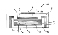
- FIG. 1 is a schematic cross-sectional view showing an example of the metal-air battery of the present invention.
- 1 includes a negative electrode case 1a, a negative electrode current collector 2 formed on the inner bottom surface of the negative electrode case 1a, a negative electrode lead 2a connected to the negative electrode current collector 2, and a negative electrode current collector.
- a negative electrode active material for example, metal Li
- a conductive material for example, carbon material
- a catalyst for example, manganese dioxide
- a binder for example, polyvinylidene fluoride
- Nonaqueous Electrolyte First, the nonaqueous electrolyte in the present invention will be described.
- the nonaqueous electrolyte in the present invention conducts metal ions between the air electrode layer and the negative electrode layer.
- the non-aqueous electrolyte in the present invention is the same as the content described in the above “A. Non-aqueous electrolyte”, and therefore description thereof is omitted here.
- the metal-air battery of the present invention preferably has a separator between the air electrode layer and the negative electrode layer. This is because a highly safe metal-air battery can be obtained.
- the separator include porous films such as polyethylene and polypropylene; and nonwoven fabrics such as a resin nonwoven fabric and a glass fiber nonwoven fabric.
- the air electrode in the present invention has an air electrode layer containing a conductive material and an air electrode current collector that collects current from the air electrode layer.
- Air electrode layer The air electrode layer used in the present invention contains at least a conductive material. Furthermore, you may contain at least one of a catalyst and a binder as needed.
- Examples of the conductive material used for the air electrode layer include a carbon material.
- Examples of the carbon material include graphite, acetylene black, carbon nanotube, carbon fiber, and mesoporous carbon.
- the content of the conductive material in the air electrode layer is, for example, preferably in the range of 10% by weight to 99% by weight, and more preferably in the range of 20% by weight to 85% by weight.
- the air electrode layer used in the present invention may contain a catalyst for promoting the reaction. This is because the electrode reaction is performed more smoothly.
- the conductive material preferably carries a catalyst.
- the catalyst include inorganic compounds such as manganese dioxide and cerium dioxide, and organic compounds (organic complexes) such as cobalt phthalocyanine.
- the catalyst content in the air electrode layer is, for example, preferably in the range of 1% by weight to 90% by weight, and more preferably in the range of 5% by weight to 50% by weight.
- the air electrode layer used in the present invention may contain a binder for fixing the conductive material.
- the binder include fluorine-based binders such as polyvinylidene fluoride (PVDF) and polytetrafluoroethylene (PTFE).
- PVDF polyvinylidene fluoride
- PTFE polytetrafluoroethylene
- rubber such as SBR may be used as the binder.
- the content of the binder in the air electrode layer is, for example, preferably 40% by weight or less, and more preferably in the range of 1% by weight to 10% by weight.
- the air electrode layer used in the present invention preferably has a porous structure. This is because the contact area between the air and the conductive material can be increased.
- the thickness of the air electrode layer varies depending on the use of the metal-air battery, but is preferably in the range of 2 ⁇ m to 500 ⁇ m, and more preferably in the range of 5 ⁇ m to 300 ⁇ m.
- Air electrode current collector used in the present invention collects the air electrode layer.
- the material for the air electrode current collector include a metal material and a carbon material.
- a carbon material is preferable. This is because the carbon material has an advantage that it has excellent corrosion resistance, an advantage that it has excellent electron conductivity, and an advantage that it has a higher energy density per weight because it is lighter than metal.
- Examples of such a carbon material include carbon fiber (carbon fiber), activated carbon (what activated a carbon plate), and the like. Among these, carbon fiber is preferable.
- the metal material include stainless steel, nickel, aluminum, and titanium.
- the structure of the air electrode current collector in the present invention is not particularly limited as long as the desired electron conductivity can be ensured, and may be a porous structure having gas diffusibility, or a dense structure having no gas diffusibility. It may be.
- the air electrode current collector preferably has a porous structure having gas diffusibility. This is because oxygen can be diffused quickly.
- the thickness of the air electrode current collector in the present invention is, for example, preferably in the range of 10 ⁇ m to 1000 ⁇ m, and more preferably in the range of 20 ⁇ m to 400 ⁇ m.
- a battery case to be described later may also have the function of an air electrode current collector.
- the negative electrode in the present invention has a negative electrode layer containing a negative electrode active material and a negative electrode current collector that collects current from the negative electrode layer.
- Negative electrode layer The negative electrode active material used in the present invention usually contains a metal, and specific examples thereof include a simple metal, an alloy, a metal oxide, and a metal nitride.
- examples of the alloy having a lithium element include a lithium aluminum alloy, a lithium tin alloy, a lithium lead alloy, and a lithium silicon alloy.
- examples of the metal oxide which has a lithium element lithium titanium oxide etc. can be mentioned, for example.
- the metal nitride containing a lithium element include lithium cobalt nitride, lithium iron nitride, and lithium manganese nitride.
- the negative electrode layer in the present invention may contain only the negative electrode active material, or may contain at least one of a conductive material and a binder in addition to the negative electrode active material.
- a negative electrode layer containing only the negative electrode active material can be obtained.
- a negative electrode layer having at least one of a conductive material and a binder can be obtained.
- Negative electrode current collector used in the present invention collects current from the negative electrode layer.
- the material for the negative electrode current collector is not particularly limited as long as it has conductivity, and examples thereof include copper, stainless steel, and nickel.
- Examples of the shape of the negative electrode current collector include a foil shape, a plate shape, and a mesh (grid) shape.
- a battery case which will be described later, may have the function of a negative electrode current collector.
- the shape of the battery case used in the present invention is not particularly limited as long as the above-described air electrode, negative electrode, and non-aqueous electrolyte can be accommodated. Specifically, a coin type, a flat plate type, a cylindrical type, A laminating type etc. can be mentioned.
- the battery case may be an open-air battery case or a sealed battery case, but is preferably an open-air battery case. As shown in FIG. 1 described above, the open-air battery case is a battery case that can come into contact with the atmosphere.
- the battery case is a sealed battery case, it is preferable to provide a gas (air) supply pipe and a discharge pipe in the sealed battery case.
- the gas to be supplied / discharged preferably has a high oxygen concentration, and more preferably pure oxygen.
- metal-air battery The type of metal ions conducted in the metal-air battery of the present invention is not particularly limited.
- the metal ion is preferably an alkali metal ion or an alkaline earth metal ion, and more preferably an alkali metal ion.
- the alkali metal ion Li ion, Na ion, K ion etc. can be mentioned, for example, Li ion is especially preferable. This is because a battery having a high energy density can be obtained.
- the alkaline earth metal ions include Mg ions and Ca ions.
- Zn ions, Al ions, Fe ions, or the like may be used as the metal ions.
- the metal-air battery of the present invention may be a primary battery or a secondary battery, but is preferably a secondary battery.
- Applications of the metal-air battery of the present invention include, for example, vehicle mounting applications, stationary power supply applications, household power supply applications, and the like.
- the method for producing the metal-air battery of the present invention is not particularly limited, and is the same as the method for producing a general metal-air battery.
- the present invention is not limited to the above embodiment.
- the above-described embodiment is an exemplification, and the present invention has the same configuration as the technical idea described in the claims of the present invention. It is included in the technical scope of the invention.
- metal Li (Honjo Metal Co., Ltd., ⁇ 18 mm, thickness 0.25 mm) was placed in the battery case.
- a polyethylene separator ( ⁇ 18 mm, thickness 25 ⁇ m) was placed on the metal Li.
- a composition having 25 parts by weight of carbon black, 42 parts by weight of MnO 2 catalyst, 33 parts by weight of polyvinylidene fluoride (PVDF), and an acetone solvent was added to a carbon paper (air electrode current collector, Toray Industries, Inc.).
- a TGP-H-090 manufactured (manufactured by TGP-H-090, ⁇ 18 mm, thickness 0.28 mm) was applied with a doctor blade to form an air electrode layer ( ⁇ 18 mm, weight per unit area 5 mg). Next, the air electrode layer of the obtained air electrode was disposed and sealed so as to face the separator to obtain an evaluation cell.
- Viscosity Viscosity (25 ° C.) was measured using the mixed solvent obtained in Production Examples 1 to 5 and the comparative sample obtained in Comparative Production Examples 1 and 2. The viscosity was measured in an Ar glove box, and the amount of water to be measured was 30 ppm or less. The results are shown in FIG.
- the viscosity in Production Examples 1 to 5 was significantly lower than that in Comparative Production Example 1. It was confirmed that the viscosity was significantly reduced even when a small amount of AN was added. In particular, in Production Example 2, it was confirmed that the viscosity was about half that of Comparative Production Example 1, and in Production Example 4, the viscosity was equivalent to that of AN.
Landscapes
- Chemical & Material Sciences (AREA)
- Engineering & Computer Science (AREA)
- Manufacturing & Machinery (AREA)
- Chemical Kinetics & Catalysis (AREA)
- Electrochemistry (AREA)
- General Chemical & Material Sciences (AREA)
- Physics & Mathematics (AREA)
- Condensed Matter Physics & Semiconductors (AREA)
- General Physics & Mathematics (AREA)
- Inorganic Chemistry (AREA)
- Hybrid Cells (AREA)
Abstract
Description
まず、本発明の非水電解質について説明する。本発明の非水電解質は、カチオン部およびアニオン部を有するイオン液体と、有機溶媒と、金属塩とを含有する非水電解質であって、上記イオン液体のカチオン部、および上記有機溶媒は、第一原理計算により算出される最大電荷が0.3以下であることを特徴とするものである。
以下、本発明の非水電解質について、構成ごとに説明する。
まず、本発明におけるイオン液体について説明する。本発明におけるイオン液体は、カチオン部およびアニオン部を有する。さらに、上記カチオン部は、上述した第一原理計算により算出される最大電荷が特定の範囲にあることを一つの特徴とする。本発明においては、上記カチオン部を有するイオン液体を単独で用いても良く、二種類以上を混合して用いても良い。また、本発明におけるイオン液体は、常温(25℃)で液体であることが好ましい。
次に、本発明における有機溶媒について説明する。本発明における有機溶媒(非水溶媒)は、上述した第一原理計算により算出される最大電荷が特定の範囲にあることを一つの特徴とする。本発明においては、上記有機溶媒を単独で用いても良く、二種類以上を混合して用いても良い。
次に、本発明における金属塩について説明する。本発明の非水電解質は、上述したイオン液体および有機溶媒の他に、通常、金属塩を含有する。本発明における金属塩は、通常、電池における正極および負極の間を伝導する金属イオンを含有するものであり、金属塩の種類は、非水電解質の用途等により異なるものである。例えば、Liイオンを含有するリチウム塩としては、LiPF6、LiBF4、LiClO4およびLiAsF6等の無機リチウム塩;およびLiCF3SO3、LiN(CF3SO2)2、LiN(C2F5SO2)2、LiC(CF3SO2)3等の有機リチウム塩等を挙げることができる。また、非水電解質における金属塩の濃度は、特に限定されるものではないが、例えば0.5mol/L~3mol/Lの範囲内であることが好ましい。
本発明の非水電解質は、イオン液体および有機溶媒のみを含有するものであっても良く、その他の化合物(例えば金属塩)をさらに含有するものであっても良い。また、本発明の非水電解質は、常温(25℃)で液体であることが好ましい。さらに、本発明の非水電解質は、粘度が低いことが好ましい。粘度が低い非水電解質を用いて電池を作製すると、電池抵抗が低くなり高電流密度域での電池の作動が容易になるからである。低粘度の非水電解質は、高電流密度域での作動が要求される車載用電池に特に有用である。本発明の非水電解質の粘度(25℃)は、例えば100mPa・s以下であることが好ましく、75mPa・s以下であることがより好ましく、50mPa・s以下であることがさらに好ましい。
次に、本発明の金属空気電池について説明する。本発明の金属空気電池は、導電性材料を含有する空気極層、および上記空気極層の集電を行う空気極集電体を有する空気極と、負極活物質を含有する負極層、および上記負極層の集電を行う負極集電体を有する負極と、上記空気極層および上記負極層の間で金属イオンの伝導を行う非水電解質とを有し、上記非水電解質が、上述した非水電解質であることを特徴とするものである。
以下、本発明の金属空気電池について、構成ごとに説明する。
まず、本発明における非水電解質について説明する。本発明における非水電解質は、空気極層および負極層の間で金属イオンの伝導を行うものである。本発明における非水電解質については、上記「A.非水電解質」に記載した内容と同様であるので、ここでの記載は省略する。
次に、本発明における空気極について説明する。本発明における空気極は、導電性材料を含有する空気極層と、上記空気極層の集電を行う空気極集電体と、を有するものである。
本発明に用いられる空気極層は、少なくとも導電性材料を含有するものである。さらに、必要に応じて、触媒および結着材の少なくとも一方を含有していても良い。
本発明に用いられる空気極集電体は、空気極層の集電を行うものである。空気極集電体の材料としては、例えば金属材料およびカーボン材料を挙げることができ、中でもカーボン材料が好ましい。カーボン材料は、耐腐食性に優れるという利点、電子伝導性に優れているという利点、金属に比べて軽いため重量当たりのエネルギー密度が高くなるという利点を有するからである。このようなカーボン材料としては、例えばカーボンファイバー(炭素繊維)、賦活カーボン(カーボン板を賦活したもの)等を挙げることができ、中でもカーボンファイバーが好ましい。一方、金属材料としては、例えばステンレス、ニッケル、アルミニウムおよびチタン等を挙げることができる。
次に、本発明における負極について説明する。本発明における負極は、負極活物質を含有する負極層と、上記負極層の集電を行う負極集電体と、を有するものである。
本発明に用いられる負極活物質は、通常、金属を含有するものであり、具体的には金属単体、合金、金属酸化物、金属窒化物等を挙げることができる。さらに、リチウム元素を有する合金としては、例えばリチウムアルミニウム合金、リチウムスズ合金、リチウム鉛合金、リチウムケイ素合金等を挙げることができる。また、リチウム元素を有する金属酸化物としては、例えばリチウムチタン酸化物等を挙げることができる。また、リチウム元素を含有する金属窒化物としては、例えばリチウムコバルト窒化物、リチウム鉄窒化物、リチウムマンガン窒化物等を挙げることができる。
本発明に用いられる負極集電体は、負極層の集電を行うものである。負極集電体の材料としては、導電性を有するものであれば特に限定されるものではないが、例えば、銅、ステンレス、ニッケル等を挙げることができる。上記負極集電体の形状としては、例えば箔状、板状およびメッシュ(グリッド)状等を挙げることができる。本発明においては、後述する電池ケースが負極集電体の機能を兼ね備えていても良い。
次に、本発明に用いられる電池ケースについて説明する。本発明に用いられる電池ケースの形状としては、上述した空気極、負極、非水電解質を収納することができれば特に限定されるものではないが、具体的にはコイン型、平板型、円筒型、ラミネート型等を挙げることができる。また、電池ケースは、大気開放型の電池ケースであっても良く、密閉型の電池ケースであっても良いが、大気開放型の電池ケースであることが好ましい。大気開放型の電池ケースは、上述した図1に示すように、大気と接触可能な電池ケースである。一方、電池ケースが密閉型電池ケースである場合は、密閉型電池ケースに、気体(空気)の供給管および排出管を設けることが好ましい。この場合、供給・排出する気体は、酸素濃度が高いことが好ましく、純酸素であることがより好ましい。また、放電時には酸素濃度を高くし、充電時には酸素濃度を低くすることが好ましい。
本発明の金属空気電池において伝導する金属イオンの種類は、特に限定されるものではない。中でも、上記金属イオンは、アルカリ金属イオンまたはアルカリ土類金属イオンであることが好ましく、アルカリ金属イオンであることがより好ましい。上記アルカリ金属イオンとしては、例えばLiイオン、NaイオンおよびKイオン等を挙げることができ、中でもLiイオンが好ましい。エネルギー密度の高い電池を得ることができるからである。上記アルカリ土類金属イオンとしては、MgイオンおよびCaイオン等を挙げることができる。また、本発明においては、上記金属イオンとして、Znイオン、Alイオン、Feイオン等を用いても良い。
イオン液体であるN-メチル-N-プロピルピペリジニウムビストリフルオロメタンスルフォニルイミド(PP13TFSI)と、有機溶媒であるアセトニトリル(AN)とを、Ar雰囲気中でPP13TFSI:AN=98:2の体積比となるように混合することにより、混合溶媒を得た。
PP13TFSIおよびANの体積比を、それぞれ、PP13TFSI:AN=95:5(作製例2)、PP13TFSI:AN=90:10(作製例3)、PP13TFSI:AN=75:25(作製例4)、PP13TFSI:AN=50:50(作製例5)に変更したこと以外は、作製例1と同様にして、混合溶媒を得た。
PP13TFSIを比較用サンプルとして用意した。
ANを比較用サンプルとして用意した。
(1)充放電サイクル試験
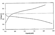
作製例1で得られた混合溶媒を用いてリチウム空気二次電池を作製した。なお、電池の組立はアルゴンボックス内で行った。また、北斗電工製の電気化学セルの電池ケースを用いた。
・放電条件:0.05mA/cm2の電流で電池電圧2.0Vになるまで放電を行う
・充電条件:0.05mA/cm2の電流で電池電圧3.85Vになるまで充電を行う
作製例1~5で得られた混合溶媒、および比較作製例1、2で得られた比較用サンプルを用いて粘度(25℃)を測定した。なお、粘度測定は、Arグローブボックス内で行い、測定対象の水分量は30ppm以下とした。その結果を図3および表1に示す。

1b … 空気極ケース
2 … 負極集電体
2a … 負極リード
3 … 負極層
4 … 空気極層
5 … 空気極集電体
5a … 空気極リード
6 … セパレータ
7 … 非水電解質
8 … 微多孔膜
9 … パッキン
Claims (7)
- カチオン部およびアニオン部を有するイオン液体と、有機溶媒と、金属塩とを含有する非水電解質であって、
前記イオン液体のカチオン部、および前記有機溶媒は、第一原理計算により算出される最大電荷が0.3以下であることを特徴とする非水電解質。 - 粘度が100mPa・s以下であることを特徴とする請求の範囲第1項に記載の非水電解質。
- 前記イオン液体が、N-メチル-N-プロピルピペリジニウムビストリフルオロメタンスルフォニルイミドであることを特徴とする請求の範囲第1項または第2項に記載の非水電解質。
- 前記有機溶媒が、アセトニトリルおよびジメトキシエタンの少なくとも一方であることを特徴とする請求の範囲第1項から第3項までのいずれかに記載の非水電解質。
- 前記イオン液体および前記有機溶媒の合計に対する前記有機溶媒の割合が、1体積%~50体積%の範囲内であることを特徴とする請求の範囲第1項から第4項までのいずれかに記載の非水電解質。
- 金属空気電池に用いられるものであることを特徴とする請求の範囲第1項から第5項までのいずれかに記載の非水電解質。
- 導電性材料を含有する空気極層、および前記空気極層の集電を行う空気極集電体を有する空気極と、負極活物質を含有する負極層、および前記負極層の集電を行う負極集電体を有する負極と、前記空気極層および前記負極層の間で金属イオンの伝導を行う非水電解質とを有し、
前記非水電解質が、請求の範囲第1項から第6項までのいずれかに記載の非水電解質であることを特徴とする金属空気電池。
Priority Applications (4)
| Application Number | Priority Date | Filing Date | Title |
|---|---|---|---|
| US13/321,986 US20130040210A1 (en) | 2010-03-10 | 2010-03-10 | Nonaqueous electrolyte and metal air battery |
| PCT/JP2010/053995 WO2011111185A1 (ja) | 2010-03-10 | 2010-03-10 | 非水電解質および金属空気電池 |
| CN2010800349991A CN102473986A (zh) | 2010-03-10 | 2010-03-10 | 非水电解质和金属空气电池 |
| JP2011541011A JP5273256B2 (ja) | 2010-03-10 | 2010-03-10 | 非水電解質および金属空気電池 |
Applications Claiming Priority (1)
| Application Number | Priority Date | Filing Date | Title |
|---|---|---|---|
| PCT/JP2010/053995 WO2011111185A1 (ja) | 2010-03-10 | 2010-03-10 | 非水電解質および金属空気電池 |
Publications (1)
| Publication Number | Publication Date |
|---|---|
| WO2011111185A1 true WO2011111185A1 (ja) | 2011-09-15 |
Family
ID=44563029
Family Applications (1)
| Application Number | Title | Priority Date | Filing Date |
|---|---|---|---|
| PCT/JP2010/053995 Ceased WO2011111185A1 (ja) | 2010-03-10 | 2010-03-10 | 非水電解質および金属空気電池 |
Country Status (4)
| Country | Link |
|---|---|
| US (1) | US20130040210A1 (ja) |
| JP (1) | JP5273256B2 (ja) |
| CN (1) | CN102473986A (ja) |
| WO (1) | WO2011111185A1 (ja) |
Cited By (5)
| Publication number | Priority date | Publication date | Assignee | Title |
|---|---|---|---|---|
| WO2013051309A1 (ja) * | 2011-10-07 | 2013-04-11 | トヨタ自動車株式会社 | リチウム空気電池用の電解液 |
| JP2013084430A (ja) * | 2011-10-07 | 2013-05-09 | Toyota Motor Corp | 空気電池用電解液 |
| JP2013084431A (ja) * | 2011-10-07 | 2013-05-09 | Toyota Motor Corp | 電解液 |
| JP2017168190A (ja) * | 2016-03-14 | 2017-09-21 | 株式会社豊田中央研究所 | リチウム空気電池 |
| US10665867B2 (en) | 2017-06-12 | 2020-05-26 | Panasonic Intellectual Property Management Co., Ltd. | Air battery including negative electrode, positive electrode, nonaqueous metal ion conductor, and oxygen evolving catalyst |
Families Citing this family (7)
| Publication number | Priority date | Publication date | Assignee | Title |
|---|---|---|---|---|
| CN103996891B (zh) * | 2013-02-19 | 2017-03-08 | 中国科学院宁波材料技术与工程研究所 | 锂‑空气电池电解液体系 |
| WO2014133466A1 (en) * | 2013-02-28 | 2014-09-04 | Nanyang Technological University | Ionic liquid electrolyte and fluorinated carbon electrode |
| EP3128589B1 (en) * | 2014-04-02 | 2018-09-26 | Zeon Corporation | Binder composition for use in secondary battery electrode, slurry composition for use in secondary battery electrode, secondary battery electrode, and secondary battery |
| EP2950380B1 (en) | 2014-05-27 | 2017-04-12 | Samsung Electronics Co., Ltd | Electrolyte for lithium air battery and lithium air battery including the same |
| CN107408744B (zh) * | 2014-12-14 | 2021-06-29 | 伊利诺伊大学董事会 | 用于先进的金属-空气蓄电池的催化剂体系 |
| US10916762B2 (en) | 2016-11-01 | 2021-02-09 | Samsung Electronics Co., Ltd. | Cathode for metal-air battery including spaces for accommodating metal oxides formed during discharge of metal-air battery and metal-air battery including the same |
| EP3404757B1 (en) | 2017-05-15 | 2019-12-04 | Samsung Electronics Co., Ltd. | Metal-air battery including a gas diffusion layer and method of manufacturing the same |
Citations (5)
| Publication number | Priority date | Publication date | Assignee | Title |
|---|---|---|---|---|
| JP2004119278A (ja) * | 2002-09-27 | 2004-04-15 | Toshiba Corp | 非水電解質空気電池 |
| JP2005190880A (ja) * | 2003-12-26 | 2005-07-14 | Toshiba Corp | 非水電解質空気電池 |
| JP2005276672A (ja) * | 2004-03-25 | 2005-10-06 | Toshiba Corp | 非水電解質電池 |
| JP2007119467A (ja) * | 2005-10-26 | 2007-05-17 | Toyota Motor Corp | 新規パーフルオロアルカンスルホンアミド化合物とその製造方法 |
| JP2008103473A (ja) * | 2006-10-18 | 2008-05-01 | Toyota Central R&D Labs Inc | 蓄電デバイス |
Family Cites Families (5)
| Publication number | Priority date | Publication date | Assignee | Title |
|---|---|---|---|---|
| US5536597A (en) * | 1993-12-17 | 1996-07-16 | Mitsubishi Gas Chemical Company | Lithium secondary battery employing a non-aqueous electrolyte |
| CN101087035B (zh) * | 2006-06-06 | 2010-10-06 | 比亚迪股份有限公司 | 一种二次锂电池用电解液及含有该电解液的二次锂电池 |
| JP5125461B2 (ja) * | 2007-01-18 | 2013-01-23 | 株式会社豊田中央研究所 | リチウム空気電池 |
| US20090286163A1 (en) * | 2008-02-29 | 2009-11-19 | The Regents Of The University Of California | Electrolyte mixtures useful for li-ion batteries |
| WO2010001892A1 (ja) * | 2008-07-04 | 2010-01-07 | ソニー株式会社 | 二次電池および電子機器 |
-
2010
- 2010-03-10 JP JP2011541011A patent/JP5273256B2/ja active Active
- 2010-03-10 CN CN2010800349991A patent/CN102473986A/zh active Pending
- 2010-03-10 US US13/321,986 patent/US20130040210A1/en not_active Abandoned
- 2010-03-10 WO PCT/JP2010/053995 patent/WO2011111185A1/ja not_active Ceased
Patent Citations (5)
| Publication number | Priority date | Publication date | Assignee | Title |
|---|---|---|---|---|
| JP2004119278A (ja) * | 2002-09-27 | 2004-04-15 | Toshiba Corp | 非水電解質空気電池 |
| JP2005190880A (ja) * | 2003-12-26 | 2005-07-14 | Toshiba Corp | 非水電解質空気電池 |
| JP2005276672A (ja) * | 2004-03-25 | 2005-10-06 | Toshiba Corp | 非水電解質電池 |
| JP2007119467A (ja) * | 2005-10-26 | 2007-05-17 | Toyota Motor Corp | 新規パーフルオロアルカンスルホンアミド化合物とその製造方法 |
| JP2008103473A (ja) * | 2006-10-18 | 2008-05-01 | Toyota Central R&D Labs Inc | 蓄電デバイス |
Cited By (8)
| Publication number | Priority date | Publication date | Assignee | Title |
|---|---|---|---|---|
| WO2013051309A1 (ja) * | 2011-10-07 | 2013-04-11 | トヨタ自動車株式会社 | リチウム空気電池用の電解液 |
| JP2013084430A (ja) * | 2011-10-07 | 2013-05-09 | Toyota Motor Corp | 空気電池用電解液 |
| JP2013084431A (ja) * | 2011-10-07 | 2013-05-09 | Toyota Motor Corp | 電解液 |
| CN103843191A (zh) * | 2011-10-07 | 2014-06-04 | 丰田自动车株式会社 | 锂空气电池用的电解液 |
| JPWO2013051309A1 (ja) * | 2011-10-07 | 2015-03-30 | トヨタ自動車株式会社 | リチウム空気電池用の電解液 |
| US9306253B2 (en) | 2011-10-07 | 2016-04-05 | Toyota Jidosha Kabushiki Kaisha | Electrolyte solution for lithium-air battery |
| JP2017168190A (ja) * | 2016-03-14 | 2017-09-21 | 株式会社豊田中央研究所 | リチウム空気電池 |
| US10665867B2 (en) | 2017-06-12 | 2020-05-26 | Panasonic Intellectual Property Management Co., Ltd. | Air battery including negative electrode, positive electrode, nonaqueous metal ion conductor, and oxygen evolving catalyst |
Also Published As
| Publication number | Publication date |
|---|---|
| US20130040210A1 (en) | 2013-02-14 |
| JP5273256B2 (ja) | 2013-08-28 |
| CN102473986A (zh) | 2012-05-23 |
| JPWO2011111185A1 (ja) | 2013-06-27 |
Similar Documents
| Publication | Publication Date | Title |
|---|---|---|
| JP5273256B2 (ja) | 非水電解質および金属空気電池 | |
| KR101376366B1 (ko) | 비수 전해액형 이차 전지 및 비수 전해액형 이차 전지용 비수 전해액 | |
| JP5170260B2 (ja) | 水系電解液電池の負極構造、及び、当該負極構造を備えた水系電解液電池 | |
| JP5373966B2 (ja) | 空気極および金属空気電池 | |
| CN105591149B (zh) | 可充电电池及其电解质配方 | |
| US8883358B2 (en) | Metal air secondary battery | |
| US9306253B2 (en) | Electrolyte solution for lithium-air battery | |
| JPWO2010073332A1 (ja) | リチウム空気電池 | |
| KR20140006639A (ko) | 리튬공지전지용 음극 및 이를 포함하는 리튬공기전지 | |
| KR101860986B1 (ko) | 리튬 공기 전지, 및 그 제조 방법 | |
| KR102237824B1 (ko) | 공기극, 이를 포함하는 리튬공기전지, 및 공기극 제조방법 | |
| JP5392356B2 (ja) | 空気電池用空気極、及び、当該空気極を備えた空気電池 | |
| KR20240089421A (ko) | 아지로다이트 유형 구조를 갖는 무기 화합물, 그 제조 방법, 및 전기화학 응용 분야에서의 그 용도 | |
| JP5556618B2 (ja) | リチウム空気電池 | |
| EP2835859B1 (en) | Electrolyte solution for lithium-air batteries, and lithium-air battery comprising the same | |
| CN120019502A (zh) | 水性电化学装置及其制备方法 | |
| KR20200095190A (ko) | 전해액 조성물 및 이를 이용한 이차전지 | |
| KR20150015643A (ko) | 리튬 공기 전지용 전해질 및 이를 포함하는 리튬 공기 전지 | |
| US20240213527A1 (en) | Battery cell | |
| EP3944273B1 (en) | Aqueous electrolyte solution for electricity storage devices and electricity storage device comprising this aqueous electrolyte solution | |
| WO2024110074A1 (en) | Electrochemical cell comprising a sulfur cathode with carbonaceous materials and sparingly solvating electrolytes, method of preparation and uses thereof | |
| WO2023007991A1 (ja) | リチウムイオン二次電池 | |
| EP3742530A1 (en) | Negative electrode, half secondary battery and secondary battery | |
| Yang | Improving the energy efficiency of Li-oxygen batteries by integrating the photo-catalyst | |
| KR20150051316A (ko) | 리튬 공기 전지용 전해질 및 이를 포함하는 리튬 공기 전지 |
Legal Events
| Date | Code | Title | Description |
|---|---|---|---|
| WWE | Wipo information: entry into national phase |
Ref document number: 201080034999.1 Country of ref document: CN |
|
| WWE | Wipo information: entry into national phase |
Ref document number: 2011541011 Country of ref document: JP |
|
| 121 | Ep: the epo has been informed by wipo that ep was designated in this application |
Ref document number: 10847415 Country of ref document: EP Kind code of ref document: A1 |
|
| WWE | Wipo information: entry into national phase |
Ref document number: 13321986 Country of ref document: US |
|
| NENP | Non-entry into the national phase |
Ref country code: DE |
|
| 122 | Ep: pct application non-entry in european phase |
Ref document number: 10847415 Country of ref document: EP Kind code of ref document: A1 |