WO2011108409A1 - 人工血管 - Google Patents
人工血管 Download PDFInfo
- Publication number
- WO2011108409A1 WO2011108409A1 PCT/JP2011/053916 JP2011053916W WO2011108409A1 WO 2011108409 A1 WO2011108409 A1 WO 2011108409A1 JP 2011053916 W JP2011053916 W JP 2011053916W WO 2011108409 A1 WO2011108409 A1 WO 2011108409A1
- Authority
- WO
- WIPO (PCT)
- Prior art keywords
- blood vessel
- artificial blood
- side end
- root
- insertion port
- Prior art date
Links
Images


Classifications
-
- A—HUMAN NECESSITIES
- A61—MEDICAL OR VETERINARY SCIENCE; HYGIENE
- A61F—FILTERS IMPLANTABLE INTO BLOOD VESSELS; PROSTHESES; DEVICES PROVIDING PATENCY TO, OR PREVENTING COLLAPSING OF, TUBULAR STRUCTURES OF THE BODY, e.g. STENTS; ORTHOPAEDIC, NURSING OR CONTRACEPTIVE DEVICES; FOMENTATION; TREATMENT OR PROTECTION OF EYES OR EARS; BANDAGES, DRESSINGS OR ABSORBENT PADS; FIRST-AID KITS
- A61F2/00—Filters implantable into blood vessels; Prostheses, i.e. artificial substitutes or replacements for parts of the body; Appliances for connecting them with the body; Devices providing patency to, or preventing collapsing of, tubular structures of the body, e.g. stents
- A61F2/02—Prostheses implantable into the body
- A61F2/04—Hollow or tubular parts of organs, e.g. bladders, tracheae, bronchi or bile ducts
- A61F2/06—Blood vessels
- A61F2/064—Blood vessels with special features to facilitate anastomotic coupling
Definitions
- the present invention relates to an artificial blood vessel used for treating an aorta or the like.
- aortic diseases such as aortic aneurysm and aortic dissection
- various artificial blood vessels suitable for this have been developed (for example, see US Pat. No. 6,777,0090).
- an intravascular treatment such as a delivery system for placing a stent graft or an imaging catheter used for confirming the placement state of the stent graft. It would be desirable to be able to insert the instrument easily and smoothly into the aorta.
- the present invention has been made in consideration of such problems of the prior art.
- An endovascular treatment instrument can be inserted easily and smoothly, and the artificial burden that can further reduce the burden and invasion of a patient.
- the purpose is to provide blood vessels.
- the present invention is an artificial blood vessel having a root-side end portion and at least one tip-side end portion communicating with the root-side end portion, between the root-side end portion and the tip-side end portion.
- an intravascular treatment instrument can be inserted into the root side end portion, and an insertion port is provided which is equipped with a check valve for preventing outflow of body fluid from the inside of the artificial blood vessel to the outside.
- the artificial blood vessel has a root-side end portion and a tip-side end portion communicating with the root-side end portion, and a check is provided between the root-side end portion and the tip-side end portion.
- An example of a technique for attaching such an artificial blood vessel to the aorta and inserting the stent graft into the arch aorta in such a way as to occlude the original arch partial branch vessel is as follows. Suturing the root end of the blood vessel to the ascending aorta, cutting the arch partial branch blood vessel (for example, the right brachiocephalic artery) from the arch aorta, stitching it to the distal end of the artificial blood vessel, Occluding the arch portion of the arch, inserting a delivery catheter from the insertion port, passing the delivery catheter through the proximal end, and proceeding to the target arch aorta to place the stent graft into the arch aorta An insertion step, and after the delivery catheter is removed from the insertion port to the outside of the body, the insertion port is excised and the excision portion is blocked. Tsu is executed by performing a flop.
- the end portion on the front end side may have a branch, and the branch may be branched at least trifurcatedly. If it does so, the branch of the tip side end part can be joined to a plurality of blood vessels, and the adaptability of the artificial blood vessel to a living body can be improved.
- the insertion port When the insertion port is provided between the branch and the root side end portion, it becomes easier to insert an intravascular treatment instrument into a biological blood vessel such as the aorta via the root side end portion. .
- the check valve includes a first valve body for preventing outflow of the body fluid in a state where the endovascular treatment instrument is inserted into the insertion port, and the check valve in a state where the endovascular treatment instrument is not inserted. It is good to have the 2nd valve body which prevents the outflow of a bodily fluid. Then, regardless of whether or not the intravascular treatment instrument is inserted into the insertion port, a high sealing performance can be ensured by the check valve.
- the second valve body is disposed in front of the insertion of the endovascular treatment instrument in the insertion port with respect to the first valve body, and the endovascular treatment instrument is slidable on the first valve body.
- the second valve body is inclined toward the insertion direction of the endovascular treatment instrument into the insertion port, and has a hole that can be brought into close contact with the outer surface of the inserted endovascular treatment instrument.
- the root side end portion can be joined to the ascending aorta, and the tip side end portion can be joined to at least one of the right brachiocephalic artery, the left common carotid artery, and the left subclavian artery. Also good.
- an artificial blood vessel has a root-side end portion and a tip-side end portion communicating with the root-side end portion, and a check valve is provided between the root-side end portion and the tip-side end portion.
- a mounted insertion port is provided.
- the stent graft can be smoothly inserted and advanced from the insertion port, for example, into the arch aorta. For this reason, the insertion can be performed easily and smoothly as compared with a method of inserting an intravascular treatment instrument such as a delivery catheter from the base of the thigh.
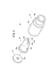
- FIG. 4A is a side cross-sectional view along the axial direction of the check valve when no endovascular treatment instrument is inserted
- FIG. 4B is an axis of the check valve when the endovascular treatment instrument is inserted.
- FIG. 1 is an explanatory view schematically showing a state in which an artificial blood vessel 10 according to an embodiment of the present invention is applied to a living body
- FIG. 2 is a perspective view showing an overall configuration of the artificial blood vessel 10.
- the artificial blood vessel 10 according to the present embodiment is used in a technique of inserting and placing a stent graft 13 into a arched aorta 12a in the treatment of a biological blood vessel, for example, the arched aorta 12a in the aorta 12.
- the artificial blood vessel 10 may be used for treatment of other sites.
- the artificial blood vessel 10 includes a large-diameter root-side end portion 14, three tip-side end portions 16 a, 16 b, and 16 c communicating with the root-side end portion 14, and these root-side portions. It has a root tube 18 connecting between the end portion 14 and the tip side end portions 16a to 16b, tip tubes 20a, 20b, 20c branched from the root tube 18, and an insertion port 22 joined to the root tube 18.
- the artificial blood vessel 10 has a base side end portion 14 joined to the ascending aorta 12c between the arch aorta 12a and the aortic valve 12b, and tip end portions 16a to 16c at the arch aorta.
- the shape and size are suitable for joining to the right brachiocephalic artery 24a, the left common carotid artery 24b, and the left subclavian artery 24c, which are 12a branch vessels.
- the root tube 18 is a tube having an outer diameter of about 12 mm to 30 mm, a thickness of about 0.1 mm to 1 mm, and a length of about 10 mm to 100 mm, and the distal end tube 20a (20b, 20c is substantially the same)
- the tube has an outer diameter of about 6 mm to 10 mm, a wall thickness of about 0.1 mm to 1 mm, and a length of about 10 mm to 150 mm.
- the root tube 18 and the tip tubes 20a to 20c may be formed of a material similar to a known artificial blood vessel, and examples thereof include polyester fibers and ePTFE (expanded polytetrafluoroethylene).
- the insertion port 22 includes a port tube 26 joined to a tube (in this case, the root tube 18) between the root-side end portion 14 and the tip-side end portions 16a to 16b, and to the root tube 18 of the port tube 26.
- the check valve 28 is mounted on the opening end opposite to the joint portion.
- the port tube 26 is formed of the same material as the root tube 18 and the tip tubes 20a to 20b, for example, and has an outer diameter of about 6 mm to 16 mm, a wall thickness of about 0.1 mm to 1 mm, and a length of 10 mm.
- the tube is about 150 mm.
- the check valve (hemostatic valve) 28 is formed of a resin material or the like having a stepped cylindrical shape in which the opening end of the port tube 26 is attached to the small diameter portion 30a.
- the housing 30 includes a first valve body 32 and a second valve body 34 that are aligned in the axial direction within the large-diameter portion 30 b of the housing 30.
- the first valve body 32 is a disk-shaped member having a hole 32a formed at the center thereof and capable of being liquid-tightly fixed to the inner wall surface of the housing 30, and is formed of an elastic body such as rubber.
- the inner diameter of the hole 32a can be inserted into an intravascular treatment instrument such as a delivery catheter 36 constituting a delivery system of the stent graft 13 such as a balloon catheter, and can be in close contact with the outer peripheral surface of the inserted delivery catheter 36. It is set (see FIGS. 1 and 4B).
- the 1st valve body 32 is a general rubber stopper, since the hole 32a is open in the state where the delivery catheter 36 is not inserted, the port tube 26 (aorta 12) side The body fluid (blood) from the outside cannot be prevented from flowing out.
- the second valve body 34 is arranged in the housing 30 on the insertion front side in the insertion direction of the delivery catheter 36 with respect to the first valve body 32.
- the second valve body 34 is provided with a disc portion 34a that can be liquid-tightly fixed to the inner wall surface of the housing 30 and a cylindrical portion 34b sandwiched from the disc portion 34a, and is inclined toward the insertion direction of the delivery catheter 36. It has a pair of inclined walls 34c and 34c, and is formed of an elastic body such as rubber.
- the cylindrical portion 34b may be omitted.
- the pair of inclined walls 34c and 34c can be in close contact with each other by forming adjacent side end portions 34d and 34d, which are end portions on the adjacent side, in a straight line. Therefore, in a state where the delivery catheter 36 is not inserted through the check valve 28, as shown in FIGS. 3 and 4A, the pair of inclined walls 34c and 34c have their proximal end portions 34d and 34d in close contact with each other.
- the pressure (blood pressure) such as body fluid (blood) from the side of the port tube 26 is applied to the outer surfaces of the both inclined walls 34c, 34c, so that the force in the direction in which these adjacent end portions 34d, 34d are in close contact with each other. The contact state is maintained.
- the pair of inclined walls 34c and 34c are forcibly separated by the delivery catheter 36 at their proximal end portions 34d and 34d.
- the delivery catheter 36 can be inserted.
- the 2nd valve body 34 is comprised as what is called a duckbill valve, when the delivery catheter 36 is not inserted, the outflow of the bodily fluid from the port tube 26 side can be prevented.
- a check valve see FIG. 4A
- the delivery catheter 36 is inserted, a gap is inevitably generated between the pair of adjacent side end portions 34d and 34d formed in a straight line, and the check The function as a valve is hardly exhibited.
- the first valve body 32 is arranged on the insertion source side of the delivery catheter 36, and the second valve body 34 is arranged in front of the delivery valve 36, so that the insertion port 22 (the check valve 28) is provided.
- a first valve body 32 that exhibits high sealing performance when the delivery catheter 36 is inserted and a second valve body 34 that exhibits high sealing performance when the delivery catheter 36 is not inserted are provided side by side. Regardless of whether or not the delivery catheter 36 is inserted, it is possible to appropriately prevent the body fluid from flowing out.
- FIG. 5 is a flowchart showing the procedure of attaching the artificial blood vessel 10 to the aorta 12 and the procedure of placing the stent graft 13 at the target position of the aorta 12 using the artificial blood vessel 10.
- the artificial blood vessel 10 is not suitably used for replacing a part of the aorta 12 but is preferably used for an operation that partially clamps the ascending aorta 12c and bypasses the right brachiocephalic artery 24a branched from the arch aorta 12a. .
- step S1 of FIG. 5 the root side end portion 14 of the artificial blood vessel 10 is sutured to the ascending aorta 12c (see FIG. 6). As shown in FIG. 6, this suturing is performed by performing partial clamping of the ascending aorta 12 c with forceps 40 without pulsating extracorporeal circulation using an oxygenator. At this time, the distal end tubes 20 a to 20 c are closed with a predetermined clamp forceps 42. The insertion port 22 is closed by a check valve 28.
- step S2 the branch vessel of the arch aorta 12a is reconstructed. That is, the right brachiocephalic artery 24a, the left common carotid artery 24b, and the left subclavian artery 24c are cut from the arch aorta 12a, sutured to the distal ends 16a to 16c of the distal tubes 20a to 20c of the artificial blood vessel 10, and cut.
- the root portions from the arch aorta 12a of the original right brachiocephalic artery 24a, left common carotid artery 24b and left subclavian artery 24c are sutured and occluded.
- step S 3 as shown in FIG. 1, a predetermined delivery catheter 36 is inserted from the insertion port 22, and the delivery catheter 36 is passed from the port tube 26 through the root tube 18 through the root side end portion 14.
- the stent graft 13 is released. Thereby, the stent graft 13 is appropriately inserted and placed at a desired site from the arch aorta 12a to the descending aorta 12d.
- step S4 first, the delivery catheter 36 is removed from the insertion port 22 to the outside of the body, and then the insertion port 22 is excised from the root tube 18 as shown in FIG. Therefore, the artificial blood vessel 10 bypasses the right brachiocephalic artery 24a, the left common carotid artery 24b, and the left subclavian artery 24c, which are branch vessels of the arch aorta 12a, and the arch aorta 12a is prosthetic with the stent graft 13. Become.
- the root-side end portion 14 and the tip-side end portions 16a to 16c communicating with the root-side end portion 14 are provided.
- An insertion port 22 to which a check valve 28 is attached is provided between the end portions 16a to 16c.
- the base end 14 is joined to the ascending aorta 12c in a state in which the ascending aorta 12c is partially clamped, and the arch portion branch blood vessels are joined to the distal ends 16a to 16c. Since circulation of the arch can be bypassed under pulsation without performing circulation, the burden and invasion of the patient can be reduced. Furthermore, the stent graft 13 can be smoothly inserted and advanced from the insertion port 22 to, for example, the arch aorta 12a.
- an intravascular treatment instrument such as a delivery catheter 36 (delivery system) for placing the stent graft 13 and a contrast catheter (not shown) for confirming the placement state of the stent graft 13 and This can be performed smoothly and the burden on the patient can be further reduced.
- the branched distal end portions 16a to 16c can be easily joined to desired branched blood vessels, respectively. ing. That is, by providing a branch at the distal end and branching the branch into at least three branches, it is possible to easily and appropriately join a plurality of blood vessels (branch blood vessels). Can improve the conformity to.
- the insertion port 22 is provided between the branch (tip side end portions 16a to 16c) and the root side end portion 14, a biological blood vessel via the root side end portion 14, for example, an aorta
- a biological blood vessel via the root side end portion 14 for example, an aorta
- the insertion port 22 is provided at a position closer to the root side end portion 14 than the branch, insertion of the intravascular treatment instrument into the aorta 12 can be further facilitated.
- the insertion port 22 may be provided in the distal end tube 20a or the like depending on an applied technique or the like.
- the check valve 28 provided in the insertion port 22 the first valve body 32 and the second valve body 34 are used, so that the delivery catheter 36 or the like is inserted into the insertion port 22. Regardless, high sealing performance can be ensured with a simple configuration, and the outflow of body fluid from the insertion port 22 can be prevented.
- At least one distal end 16a to 16c may be provided according to the surgical procedure, and the number of distal tubes 20a to 20b can be changed correspondingly.
- the configuration of the check valve 28 attached to the insertion port 22 may be other than the configuration using the first valve body 32 and the second valve body 34 described above. What is necessary is just to be able to ensure a high sealing performance regardless of whether or not a therapeutic instrument is inserted.
Landscapes
- Health & Medical Sciences (AREA)
- Gastroenterology & Hepatology (AREA)
- Pulmonology (AREA)
- Cardiology (AREA)
- Oral & Maxillofacial Surgery (AREA)
- Transplantation (AREA)
- Engineering & Computer Science (AREA)
- Biomedical Technology (AREA)
- Heart & Thoracic Surgery (AREA)
- Vascular Medicine (AREA)
- Life Sciences & Earth Sciences (AREA)
- Animal Behavior & Ethology (AREA)
- General Health & Medical Sciences (AREA)
- Public Health (AREA)
- Veterinary Medicine (AREA)
- Prostheses (AREA)
Abstract
本発明は人工血管に関し、人工血管(10)は、根元側端部(14)と、該根元側端部(14)に連通する少なくとも1つの先端側端部(16a)とを有し、根元側端部(14)と先端側端部(16a)との間には、根元側端部(14)へと血管内治療器具であるデリバリーカテーテル(36)等を挿通可能であると共に、当該人工血管(10)内から外部への体液の流出を防止する逆止弁(28)が装着された挿入ポート(22)が設けられる。例えば、根元側端部(14)は、上行大動脈(12c)に接合され、先端側端部(16a、16b、16c)はそれぞれ右腕頭動脈(24a)、左総頚動脈(24b)、左鎖骨下動脈(24c)に接合される。
Description
本発明は、大動脈等の治療に用いられる人工血管に関する。
例えば、大動脈瘤や大動脈解離等の大動脈疾患の治療は、弓部大動脈等を人工血管で置換する外科手術を行うことが一般的であり、これに適した各種の人工血管が開発されている(例えば、米国特許第6770090号明細書参照)。
このような置換術は、人工心肺装置を用いた体外循環を使用する必要があり、また、上行大動脈や弓部大動脈から下行大動脈まで達するような広範囲の治療を必要とする場合には、切開範囲も広くなることから、患者の手術負担や手術侵襲が非常に大きいものとなっている。
そこで、上記の置換術に代えて、例えば、上行大動脈をパーシャルクランピングし、弓部大動脈から分枝した右腕頭動脈や左総頚動脈等の弓部分枝血管をバイパスする人工血管を接合した後、元の大動脈の弓部分枝部分を閉塞させる方法でステントグラフトを該大動脈内に挿入する種々の術式が考案されている。
そして、この種の術式では、患者に対する負担や侵襲をより低減するため、例えば、ステントグラフトを留置するためのデリバリーシステムや、ステントグラフトの留置状態を確認するために用いる造影用カテーテル等の血管内治療器具を大動脈内に容易に且つ円滑に挿入できることが望まれている。
本発明はこのような従来技術の課題を考慮してなされたものであり、血管内治療器具を容易に且つ円滑に挿入可能であり、患者の負担や侵襲を一層低減することが可能となる人工血管を提供することを目的とする。
本発明は、根元側端部と、該根元側端部に連通する少なくとも1つの先端側端部とを有する人工血管であって、前記根元側端部と前記先端側端部との間には、前記根元側端部へと血管内治療器具を挿通可能であると共に、当該人工血管内から外部への体液の流出を防止する逆止弁が装着された挿入ポートが設けられていることを特徴とする。
このような構成によれば、人工血管において、根元側端部と、該根元側端部に連通する先端側端部を有し、これら根元側端部と先端側端部との間に逆止弁が装着された挿入ポートが設けられたことにより、例えば、上行大動脈をパーシャルクランピングした状態で根元側端部を上行大動脈に接合し、先端側端部に弓部分枝血管を接合することで、人工心肺装置による体外循環を行わず、拍動下で弓部分枝血管をバイパスすることができるため、患者の負担や侵襲を低減することができる。さらに、挿入ポートから例えば弓部大動脈へとステントグラフトを円滑に挿入し、進行させることができる。このため、デリバリーカテーテル等の血管内治療器具を太ももの付け根等から挿入する方法に比べて、その挿入を容易に且つ円滑に行うことができる。
このような人工血管を大動脈に取り付け、元の弓部分枝血管を閉塞させる形でステントグラフトを弓部大動脈に挿入する手技の一例としては、拍動下で上行大動脈をパーシャルクランピングした状態で、人工血管の根元側端部を上行大動脈に縫合するステップと、弓部分枝血管(例えば、右腕頭動脈)を弓部大動脈から切断し、人工血管の先端側端部に縫合すると共に、切断された元の弓部分枝血管を閉塞するステップと、挿入ポートからデリバリーカテーテルを挿入すると共に、該デリバリーカテーテルを根元側端部を通過させ、目的部位である弓部大動脈まで進めてステントグラフトを該弓部大動脈に挿入するステップと、デリバリーカテーテルを挿入ポートから体外へと抜去した後、該挿入ポートを切除し、その切除部を閉塞するステップとを行うことで実行される。
前記先端側端部は分岐を有する構成としてもよく、さらに、該分岐は少なくとも三叉に分岐していてもよい。そうすると、先端側端部の分岐を複数の血管に対して接合することができ、当該人工血管の生体への適合性を高めることができる。
前記挿入ポートは、前記分岐と前記根元側端部の間に設けられていると、根元側端部を経由しての生体血管、例えば大動脈内への血管内治療器具の挿入が一層容易となる。
前記逆止弁は、前記挿入ポートに前記血管内治療器具が挿入されている状態での前記体液の流出を防止する第1弁体と、前記血管内治療器具が挿入されていない状態での前記体液の流出を防止する第2弁体とを有するとよい。そうすると、挿入ポートへの血管内治療器具の挿入の有無にかかわらず、逆止弁で高いシール性を確保することができる。
この場合、前記第1弁体よりも前記第2弁体が前記挿入ポートにおける前記血管内治療器具の挿入前方側に配置され、前記第1弁体は、前記血管内治療器具が摺動可能に挿通されると共に、該挿通された前記血管内治療器具の外面に密着可能な孔部を有し、前記第2弁体は、前記血管内治療器具の前記挿入ポートへの挿入方向に向いて傾斜した一対の傾斜壁を有し、両傾斜壁の近接側端部が互いに密着及び離間することにより、該両傾斜壁の間に前記血管内治療器具が挿通可能であると、挿入ポートへの血管内治療器具の挿入の有無にかかわらず高いシール性を有する逆止弁を簡単な構造で実現することができる。
前記根元側端部は、上行大動脈に接合可能であり、前記先端側端部は、右腕頭動脈、左総頚動脈及び左鎖骨下動脈のうちの少なくとも1つに接合可能であるように構成してもよい。
本発明によれば、人工血管において、根元側端部と、該根元側端部に連通する先端側端部を有し、これら根元側端部と先端側端部との間に逆止弁が装着された挿入ポートが設けられる。これにより、例えば、上行大動脈をパーシャルクランピングした状態で根元側端部を上行大動脈に接合し、先端側端部に弓部分枝血管を接合することで、人工心肺装置による体外循環を行わず、拍動下で弓部分枝血管をバイパスすることができるため、患者の負担や侵襲を低減することができる。さらに、挿入ポートから例えば弓部大動脈へとステントグラフトを円滑に挿入し、進行させることができる。このため、デリバリーカテーテル等の血管内治療器具を太ももの付け根等から挿入する方法に比べて、その挿入を容易に且つ円滑に行うことができる。
以下、本発明に係る人工血管について好適な実施の形態を挙げ、添付の図面を参照しながら説明する。
図1は、本発明の一実施形態に係る人工血管10を生体に適用した状態を模式的に示す説明図であり、図2は、人工血管10の全体構成を示す斜視図である。本実施形態に係る人工血管10は、生体血管、例えば大動脈12における弓部大動脈12aの治療において、該弓部大動脈12a内へとステントグラフト13を挿入・留置する術式に用いられる。勿論、人工血管10を他の部位の治療に用いてもよいことは言うまでもない。
図1及び図2に示すように、人工血管10は、大径の根元側端部14と、該根元側端部14に連通する3つの先端側端部16a、16b、16cと、これら根元側端部14と先端側端部16a~16bとの間を繋ぐ根元チューブ18及び該根元チューブ18から分岐した先端チューブ20a、20b、20cと、根元チューブ18に接合された挿入ポート22とを有する。
図1から諒解されるように、人工血管10は、根元側端部14が弓部大動脈12aと大動脈弁12bとの間の上行大動脈12cに接合され、先端側端部16a~16cが弓部大動脈12aの分枝血管である右腕頭動脈24a、左総頚動脈24b及び左鎖骨下動脈24cにそれぞれ接合されるのに適した形状・寸法で構成されている。例えば、根元チューブ18は、外径が12mm~30mm程度、肉厚が0.1mm~1mm程度、長さが10mm~100mm程度のチューブであり、先端チューブ20a(20b、20cも略同様)は、外径が6mm~10mm程度、肉厚が0.1mm~1mm程度、長さが10mm~150mm程度のチューブである。これら根元チューブ18及び先端チューブ20a~20cは、公知の人工血管と同様な素材で形成すればよく、例えば、ポリエステル繊維やePTFE(延伸ポリテトラフルオロエチレン)等が挙げられる。
挿入ポート22は、根元側端部14と先端側端部16a~16bとの間のチューブ(この場合は、根元チューブ18)に接合されたポートチューブ26と、該ポートチューブ26の根元チューブ18への接合部とは反対側の開口端に装着された逆止弁28とから構成されている。ポートチューブ26は、例えば、上記した根元チューブ18及び先端チューブ20a~20bと同様な素材で形成されると共に、外径が6mm~16mm程度、肉厚が0.1mm~1mm程度、長さが10mm~150mm程度のチューブである。
図3、図4A及び図4Bに示すように、逆止弁(止血弁)28は、小径部30aにポートチューブ26の前記開口端が装着される段付き円筒形状で樹脂材料等により形成されたハウジング30と、ハウジング30の大径部30b内で軸方向に並んだ第1弁体32及び第2弁体34とから構成されている。
第1弁体32は、その中心に孔部32aが形成され、ハウジング30の内壁面に液密に固着可能な円板状の部材であり、ゴム等の弾性体により形成されている。孔部32aの内径は、バルーンカテーテル等、ステントグラフト13のデリバリーシステムを構成するデリバリーカテーテル36等の血管内治療器具を挿通可能であると共に、挿通されたデリバリーカテーテル36の外周面に密着可能な寸法に設定される(図1及び図4B参照)。
このように、第1弁体32は、一般的なゴム栓であることから、デリバリーカテーテル36が挿通されていない状態では、孔部32aが開放されているため、ポートチューブ26(大動脈12)側からの体液(血液)等の外部への流出を防止することはできない構造となっている。
第2弁体34は、ハウジング30内において、第1弁体32よりもデリバリーカテーテル36の挿入方向における挿入前方側に配置される。第2弁体34は、ハウジング30の内壁面に液密に固着可能な円板部34aと、円板部34aから円筒部34bを挟んで設けられ、デリバリーカテーテル36の挿入方向に向いて傾斜した一対の傾斜壁34c、34cとを有し、ゴム等の弾性体によって形成されている。円筒部34bは省略してもよい。
図3に示すように、一対の傾斜壁34c、34cは、その近接する側の端部である近接側端部34d、34dが直線状に形成されて互いに密着可能である。そこで、逆止弁28にデリバリーカテーテル36が挿通されていない状態では、図3及び図4Aに示すように、一対の傾斜壁34c、34cは、その近接側端部34d、34dが互いに密着しており、ポートチューブ26側からの体液(血液)等の圧力(血圧)が両傾斜壁34c、34cの外面に付与されることで、これら近接側端部34d、34dが互いに密着する方向の力を受け、その密着状態が維持される。一方、逆止弁28にデリバリーカテーテル36が挿通された状態では、図4Bに示すように、一対の傾斜壁34c、34cは、その近接側端部34d、34dがデリバリーカテーテル36によって強制的に離間されることで、該デリバリーカテーテル36が挿通可能となっている。
このように、第2弁体34は、いわゆるダックビル弁として構成されているため、デリバリーカテーテル36が挿通されていない状態では、ポートチューブ26側からの体液の外部への流出を防止することができる逆止弁として機能するが(図4A参照)、デリバリーカテーテル36が挿通された状態では、直線状に形成された一対の近接側端部34d、34d間に必然的に隙間が生じ、その逆止弁としての機能はほとんど発揮されることはない。
そこで、逆止弁28では、デリバリーカテーテル36の挿入元側に第1弁体32を配置し、その前方に第2弁体34を配置したことにより、当該挿入ポート22(逆止弁28)にデリバリーカテーテル36が挿入されている状態で高いシール性を発揮する第1弁体32と、デリバリーカテーテル36が挿入されていない状態で高いシール性を発揮する第2弁体34とが並設され、デリバリーカテーテル36の挿入状態の有無に係わらず、体液の外部への流出を適切に防止することが可能となっている。
次に、以上のように構成される人工血管10について、該人工血管10を大動脈12に取り付ける際の手技及び作用について説明する。
図5は、人工血管10の大動脈12への取り付け及び該人工血管10を用いてステントグラフト13を大動脈12の目的位置に留置する手技の手順を示すフローチャートである。人工血管10は、大動脈12の一部を置換する術式ではなく、上行大動脈12cをパーシャルクランピングし、弓部大動脈12aから分枝した右腕頭動脈24a等をバイパスする術式に好適に用いられる。
先ず、図5のステップS1において、人工血管10の根元側端部14を上行大動脈12cに縫合する(図6参照)。この縫合は、図6に示すように、人工心肺装置による体外循環を行わず、拍動下で上行大動脈12cの一部を鉗子40によってパーシャルクランピングして実施する。この際、先端チューブ20a~20cは、所定のクランプ鉗子42で閉塞しておく。なお、挿入ポート22は、逆止弁28によって閉塞されている。
ステップS2において、図7に示すように、弓部大動脈12aの分枝血管を再建する。すなわち、右腕頭動脈24a、左総頚動脈24b及び左鎖骨下動脈24cを弓部大動脈12aから切断し、人工血管10の先端チューブ20a~20cの先端側端部16a~16cにそれぞれ縫合すると共に、切断された元の右腕頭動脈24a、左総頚動脈24b及び左鎖骨下動脈24cの弓部大動脈12aからの根元部分を縫合・閉塞する。
ステップS3では、図1に示すように、挿入ポート22から所定のデリバリーカテーテル36を挿入すると共に、該デリバリーカテーテル36をポートチューブ26から根元チューブ18を介して根元側端部14を通過させ、目的部位である弓部大動脈12aまで進めた後、ステントグラフト13を開放する。これにより、ステントグラフト13は、弓部大動脈12aから下行大動脈12dにかけた所望部位に適切に挿入・留置される。
ステップS4では、先ず、デリバリーカテーテル36を挿入ポート22から体外へと抜去した後、図8に示すように、該挿入ポート22を根元チューブ18から切除し、その切除部44を縫合・閉塞する。従って、人工血管10により弓部大動脈12aの分枝血管である右腕頭動脈24a、左総頚動脈24b及び左鎖骨下動脈24cがバイパスされると共に、弓部大動脈12aがステントグラフト13で補綴されることになる。
以上のように、本実施形態に係る人工血管10によれば、根元側端部14と、該根元側端部14に連通する先端側端部16a~16cを有し、これら根元側端部14と先端側端部16a~16cとの間に逆止弁28が装着された挿入ポート22が設けられている。
従って、例えば、上行大動脈12cをパーシャルクランピングした状態で根元側端部14を上行大動脈12cに接合し、先端側端部16a~16cに弓部分枝血管を接合することで、人工心肺装置による体外循環を行わず、拍動下で弓部分枝血管をバイパスすることができるため、患者の負担や侵襲を低減することができる。さらに、挿入ポート22から例えば弓部大動脈12aへとステントグラフト13を円滑に挿入し、進行させることができる。このため、ステントグラフト13を留置するためのデリバリーカテーテル36(デリバシーシステム)や、ステントグラフト13の留置状態を確認するための造影用カテーテル(図示せず)等の血管内治療器具の挿入を容易に且つ円滑に行うことができ、患者の負担も一層低減することができる。
人工血管10では、少なくとも三叉に分岐した先端側端部16a~16cを有しているため、該分岐した先端側端部16a~16cをそれぞれ所望の分岐血管に容易に接合することが可能となっている。すなわち、先端側端部に分岐を設け、該分岐を少なくとも三叉に分岐させたことにより、複数の血管(分岐血管)に対して容易に且つ適切に接合することができ、当該人工血管10の生体への適合性を高めることができる。
この際、前記挿入ポート22が、前記分岐(先端側端部16a~16c)と根元側端部14の間に設けられているため、根元側端部14を経由しての生体血管、例えば大動脈内への血管内治療器具の挿入が一層容易となっている。さらに、挿入ポート22が前記分岐よりも根元側端部14に近接した位置に設けられていることにより、大動脈12内への血管内治療器具の挿入をより一層容易なものとすることができる。勿論、適用される術式等によっては、挿入ポート22を先端チューブ20a等に設けてもよい。
しかも、挿入ポート22に設ける逆止弁28として、上記した第1弁体32及び第2弁体34を用いた構成とすることにより、該挿入ポート22へのデリバリーカテーテル36等の挿入の有無にかかわらず高いシール性を簡単な構成で確保することができ、該挿入ポート22からの体液の流出を防止することができる。
なお、本発明は、上述の実施の形態に限らず、本発明の要旨を逸脱することなく、種々の構成乃至工程を採り得ることは勿論である。
例えば、先端側端部16a~16cは、術式に応じて少なくとも1つ設けてあればよく、これに対応して先端チューブ20a~20bの本数も変更可能である。
挿入ポート22に装着される逆止弁28の構成は、上記した第1弁体32及び第2弁体34を用いた構成以外であっても勿論よく、要は、挿入ポート22への血管内治療器具の挿入の有無にかかわらず高いシール性を確保することができるものであればよい。
Claims (7)
- 根元側端部(14)と、該根元側端部(14)に連通する少なくとも1つの先端側端部(16a)とを有する人工血管であって、
前記根元側端部(14)と前記先端側端部(16a)との間には、前記根元側端部(14)へと血管内治療器具(36)を挿通可能であると共に、当該人工血管内から外部への体液の流出を防止する逆止弁(28)が装着された挿入ポート(22)が設けられていることを特徴とする人工血管。 - 請求項1記載の人工血管において、
前記先端側端部(16a)は分岐を有することを特徴とする人工血管。 - 請求項2記載の人工血管において、
前記分岐は少なくとも三叉に分岐していることを特徴とする人工血管。 - 請求項2又は3記載の人工血管において、
前記挿入ポート(22)は、前記分岐と前記根元側端部(14)の間に設けられていることを特徴とする人工血管。 - 請求項1記載の人工血管において、
前記逆止弁(28)は、前記挿入ポート(22)に前記血管内治療器具(36)が挿入されている状態での前記体液の流出を防止する第1弁体(32)と、前記血管内治療器具(36)が挿入されていない状態での前記体液の流出を防止する第2弁体(34)とを有することを特徴とする人工血管。 - 請求項5記載の人工血管において、
前記第1弁体(32)よりも前記第2弁体(34)が前記挿入ポート(22)における前記血管内治療器具(36)の挿入前方側に配置され、
前記第1弁体(32)は、前記血管内治療器具(36)が摺動可能に挿通されると共に、該挿通された前記血管内治療器具(36)の外面に密着可能な孔部(32a)を有し、
前記第2弁体(34)は、前記血管内治療器具(36)の前記挿入ポート(22)への挿入方向に向いて傾斜した一対の傾斜壁(34c)を有し、両傾斜壁(34c)の近接側端部(34d)が互いに密着及び離間することにより、該両傾斜壁(34c)の間に前記血管内治療器具(36)が挿通可能であることを特徴とする人工血管。 - 請求項1記載の人工血管において、
前記根元側端部(14)は、上行大動脈(12c)に接合可能であり、
前記先端側端部(16a)は、右腕頭動脈(24a)、左総頚動脈(24b)及び左鎖骨下動脈(24c)のうちの少なくとも1つに接合可能であることを特徴とする人工血管。
Priority Applications (4)
| Application Number | Priority Date | Filing Date | Title |
|---|---|---|---|
| ES11750519T ES2766450T3 (es) | 2010-03-04 | 2011-02-23 | Vaso sanguíneo artificial |
| EP11750519.8A EP2543342B1 (en) | 2010-03-04 | 2011-02-23 | Artificial blood vessel |
| JP2012503077A JP5301726B2 (ja) | 2010-03-04 | 2011-02-23 | 人工血管 |
| US13/544,334 US20120277849A1 (en) | 2010-03-04 | 2012-07-09 | Artificial blood vessel |
Applications Claiming Priority (2)
| Application Number | Priority Date | Filing Date | Title |
|---|---|---|---|
| JP2010047282 | 2010-03-04 | ||
| JP2010-047282 | 2010-03-04 |
Related Child Applications (1)
| Application Number | Title | Priority Date | Filing Date |
|---|---|---|---|
| US13/544,334 Continuation US20120277849A1 (en) | 2010-03-04 | 2012-07-09 | Artificial blood vessel |
Publications (1)
| Publication Number | Publication Date |
|---|---|
| WO2011108409A1 true WO2011108409A1 (ja) | 2011-09-09 |
Family
ID=44542063
Family Applications (1)
| Application Number | Title | Priority Date | Filing Date |
|---|---|---|---|
| PCT/JP2011/053916 WO2011108409A1 (ja) | 2010-03-04 | 2011-02-23 | 人工血管 |
Country Status (5)
| Country | Link |
|---|---|
| US (1) | US20120277849A1 (ja) |
| EP (1) | EP2543342B1 (ja) |
| JP (1) | JP5301726B2 (ja) |
| ES (1) | ES2766450T3 (ja) |
| WO (1) | WO2011108409A1 (ja) |
Cited By (6)
| Publication number | Priority date | Publication date | Assignee | Title |
|---|---|---|---|---|
| US20130274853A1 (en) * | 2012-04-12 | 2013-10-17 | Sanford Health | Debranching Great Vessel Stent Graft and Methods for Use |
| US9949818B2 (en) | 2012-12-14 | 2018-04-24 | Sanford Health | Combination double-barreled and debranching stent grafts and methods for use |
| CN109009562A (zh) * | 2018-08-27 | 2018-12-18 | 泉州市第医院 | 改进型的主动脉弓覆膜支架型血管 |
| US10357353B2 (en) | 2012-04-12 | 2019-07-23 | Sanford Health | Combination double-barreled and debranching stent grafts and methods for use |
| JP2019528946A (ja) * | 2016-09-30 | 2019-10-17 | バスクテック リミテッドVascutek Limited | 血管グラフト |
| JP2020534884A (ja) * | 2017-09-27 | 2020-12-03 | バスクテック リミテッドVascutek Limited | 管腔内デバイス |
Families Citing this family (5)
| Publication number | Priority date | Publication date | Assignee | Title |
|---|---|---|---|---|
| AU2013245879B2 (en) * | 2012-04-12 | 2017-06-15 | Sanford Health | Combination double-barreled and debranching stent grafts and methods for use |
| AU2016335761B2 (en) * | 2015-10-09 | 2020-12-03 | Vasoptic Medical, Inc. | System and method for rapid examination of vasculature and particulate flow using laser speckle contrast imaging |
| GB201615219D0 (en) | 2016-09-07 | 2016-10-19 | Vascutek Ltd And Univ Medical Center Hamburg-Eppendorf (Uke) | Hybrid prosthesis and delivery system |
| GB201707929D0 (en) | 2017-05-17 | 2017-06-28 | Vascutek Ltd | Tubular medical device |
| CN107468374A (zh) * | 2017-09-07 | 2017-12-15 | 马路遥 | 主动脉弓部置换术灌注用四分支人造血管 |
Citations (4)
| Publication number | Priority date | Publication date | Assignee | Title |
|---|---|---|---|---|
| US6770090B2 (en) | 2001-12-07 | 2004-08-03 | Scimed Life Systems, Inc. | Anatomically curved graft for implantation at the aortic arch |
| WO2006013234A1 (fr) * | 2004-07-02 | 2006-02-09 | Daniel Roux | Prothese vasculaire permettant une adaptation aux differences de diametre entre les deux extremites d’un segment de vaisseau sanguin a remplacer |
| US20070067014A1 (en) * | 2005-09-22 | 2007-03-22 | Microport Medical Co., Ltd. | Method for aortic graft installation |
| WO2009082718A1 (en) * | 2007-12-21 | 2009-07-02 | Feinstein Ara J | Devices, systems, and methods for repair of vascular defects |
Family Cites Families (17)
| Publication number | Priority date | Publication date | Assignee | Title |
|---|---|---|---|---|
| US4436519A (en) * | 1981-05-28 | 1984-03-13 | Argon Medical Corp. | Removable hemostasis valve |
| US4501263A (en) * | 1982-03-31 | 1985-02-26 | Harbuck Stanley C | Method for reducing hypertension of a liver |
| US4524805A (en) * | 1983-07-08 | 1985-06-25 | Hoffman Allan C | Normally closed duckbill valve and method of manufacture |
| US5290263A (en) * | 1989-02-02 | 1994-03-01 | Regents Of The University Of Minnesota | Bidirectional check valve catheter |
| US5330451A (en) * | 1992-12-17 | 1994-07-19 | Shelhigh, Inc. | Multi purpose perfusion cannula |
| US5599305A (en) * | 1994-10-24 | 1997-02-04 | Cardiovascular Concepts, Inc. | Large-diameter introducer sheath having hemostasis valve and removable steering mechanism |
| US5755682A (en) * | 1996-08-13 | 1998-05-26 | Heartstent Corporation | Method and apparatus for performing coronary artery bypass surgery |
| US5655548A (en) * | 1996-09-16 | 1997-08-12 | Circulation, Inc. | Method for treatment of ischemic heart disease by providing transvenous myocardial perfusion |
| US6090067A (en) * | 1998-02-19 | 2000-07-18 | Carter; Bruce C. | Surface access hemostatic valve |
| US6024729A (en) * | 1998-03-10 | 2000-02-15 | Vernay Laboratories, Inc. | Hemostasis valve assembly including guide wire seal |
| AU761192B2 (en) * | 1998-06-10 | 2003-05-29 | Converge Medical, Inc. | Sutureless anastomosis systems |
| US6537290B2 (en) * | 2001-03-05 | 2003-03-25 | Edwards Lifesciences Corporation | Sealing access cannula system |
| US6913609B2 (en) * | 2001-09-28 | 2005-07-05 | Cardica, Inc. | Access port system for anastomosis |
| US20040162607A1 (en) * | 2002-12-30 | 2004-08-19 | Saqib Masroor | Prosthetic arterial graft with test port |
| DE602004031974D1 (de) * | 2003-12-11 | 2011-05-05 | Cook Inc | Hämostaseventilanordnung |
| US20060047335A1 (en) * | 2004-08-26 | 2006-03-02 | Israel Henry M | Catheter with deflector |
| US9707113B2 (en) * | 2006-04-19 | 2017-07-18 | Cook Medical Technologies Llc | Twin bifurcated stent graft |
-
2011
- 2011-02-23 JP JP2012503077A patent/JP5301726B2/ja active Active
- 2011-02-23 ES ES11750519T patent/ES2766450T3/es active Active
- 2011-02-23 EP EP11750519.8A patent/EP2543342B1/en active Active
- 2011-02-23 WO PCT/JP2011/053916 patent/WO2011108409A1/ja active Application Filing
-
2012
- 2012-07-09 US US13/544,334 patent/US20120277849A1/en not_active Abandoned
Patent Citations (5)
| Publication number | Priority date | Publication date | Assignee | Title |
|---|---|---|---|---|
| US6770090B2 (en) | 2001-12-07 | 2004-08-03 | Scimed Life Systems, Inc. | Anatomically curved graft for implantation at the aortic arch |
| JP2005511200A (ja) * | 2001-12-07 | 2005-04-28 | ボストン・サイエンティフィック・リミテッド | 大動脈弓のところに埋設するための解剖学的に湾曲したグラフト |
| WO2006013234A1 (fr) * | 2004-07-02 | 2006-02-09 | Daniel Roux | Prothese vasculaire permettant une adaptation aux differences de diametre entre les deux extremites d’un segment de vaisseau sanguin a remplacer |
| US20070067014A1 (en) * | 2005-09-22 | 2007-03-22 | Microport Medical Co., Ltd. | Method for aortic graft installation |
| WO2009082718A1 (en) * | 2007-12-21 | 2009-07-02 | Feinstein Ara J | Devices, systems, and methods for repair of vascular defects |
Non-Patent Citations (1)
| Title |
|---|
| See also references of EP2543342A4 |
Cited By (17)
| Publication number | Priority date | Publication date | Assignee | Title |
|---|---|---|---|---|
| US10492900B2 (en) | 2012-04-12 | 2019-12-03 | Sanford Health | Debranching great vessel stent graft and methods for use |
| US9393102B2 (en) * | 2012-04-12 | 2016-07-19 | Sanford Health | Debranching great vessel stent graft and methods for use |
| US11419713B2 (en) | 2012-04-12 | 2022-08-23 | Sanford Health | Debranching visceral stent graft and methods for use |
| US9370413B2 (en) | 2012-04-12 | 2016-06-21 | Sanford Health | Combination double-barreled and debranching stent graft and methods for use |
| US10350052B2 (en) | 2012-04-12 | 2019-07-16 | Sanford Health | Debranching visceral stent graft and methods for use |
| US9393101B2 (en) | 2012-04-12 | 2016-07-19 | Sanford Health | Visceral double-barreled main body stent graft and methods for use |
| US9427308B2 (en) | 2012-04-12 | 2016-08-30 | Sanford Health | Debranching visceral stent graft and methods for use |
| US10357353B2 (en) | 2012-04-12 | 2019-07-23 | Sanford Health | Combination double-barreled and debranching stent grafts and methods for use |
| US9283068B2 (en) | 2012-04-12 | 2016-03-15 | Sanford Health | Debranching visceral stent graft and methods for use |
| US8734504B2 (en) | 2012-04-12 | 2014-05-27 | Sanford Health | Aortic arch double-barreled main body stent graft and methods for use |
| US20130274853A1 (en) * | 2012-04-12 | 2013-10-17 | Sanford Health | Debranching Great Vessel Stent Graft and Methods for Use |
| US9949818B2 (en) | 2012-12-14 | 2018-04-24 | Sanford Health | Combination double-barreled and debranching stent grafts and methods for use |
| JP2019528946A (ja) * | 2016-09-30 | 2019-10-17 | バスクテック リミテッドVascutek Limited | 血管グラフト |
| JP2020534884A (ja) * | 2017-09-27 | 2020-12-03 | バスクテック リミテッドVascutek Limited | 管腔内デバイス |
| JP7249330B2 (ja) | 2017-09-27 | 2023-03-30 | バスクテック リミテッド | 管腔内デバイス |
| CN109009562A (zh) * | 2018-08-27 | 2018-12-18 | 泉州市第医院 | 改进型的主动脉弓覆膜支架型血管 |
| CN109009562B (zh) * | 2018-08-27 | 2023-11-21 | 泉州市第一医院 | 改进型的主动脉弓覆膜支架型血管 |
Also Published As
| Publication number | Publication date |
|---|---|
| EP2543342B1 (en) | 2019-11-13 |
| US20120277849A1 (en) | 2012-11-01 |
| JPWO2011108409A1 (ja) | 2013-06-27 |
| JP5301726B2 (ja) | 2013-09-25 |
| EP2543342A1 (en) | 2013-01-09 |
| EP2543342A4 (en) | 2017-07-05 |
| ES2766450T3 (es) | 2020-06-12 |
Similar Documents
| Publication | Publication Date | Title |
|---|---|---|
| JP5301726B2 (ja) | 人工血管 | |
| US9566146B2 (en) | Cardiovascular valve and valve housing apparatuses and systems | |
| ES2543960T3 (es) | Dispositivo para anastomosis término-lateral | |
| JP6853169B2 (ja) | バスキュラアクセス | |
| JP4556949B2 (ja) | 冠状動脈バイパス術用処置具 | |
| JP6825086B2 (ja) | ハイブリッド人工器官およびデリバリーシステム | |
| US10314591B2 (en) | Medical device and corresponding method of use for arteriovenous fistula creation | |
| US8480693B2 (en) | Method and device for temporary emergency vessel anastomoses | |
| JP5866131B2 (ja) | 吻合コネクター | |
| JP3939364B2 (ja) | 拍動下冠動脈バイパス術用補助具 | |
| US8617191B2 (en) | Probe coupler assembly | |
| JP2005237945A (ja) | 冠状動脈バイパス術用処置具 | |
| JP2020534884A (ja) | 管腔内デバイス | |
| US20030065344A1 (en) | Method and device for creating microvascular anastomoses | |
| US20040162607A1 (en) | Prosthetic arterial graft with test port | |
| KR101598704B1 (ko) | 이중 봉합부를 포함하는 복합이식편 | |
| WO2022207505A2 (en) | Devices and methods for fistula-free hemodialysis | |
| CN109745144B (zh) | 覆膜支架 | |
| CN218220394U (zh) | 一种具有打结位点的人工血管 | |
| US9603601B2 (en) | Occlusion devices including dual balloons and related methods | |
| US20150257759A1 (en) | Implant for facilitating sutured side-to-side arteriovenous fistula creation and maintaining patency | |
| CN115024857A (zh) | 一种用于主动脉手术的人工血管 | |
| TW202335619A (zh) | 用於將醫療裝置固定至患者之設備及方法 | |
| WO2023131688A1 (en) | Devices and methods for percutaneous bypass | |
| JP2024510273A (ja) | 可撓性インサートアセンブリを含む結紮クリップ |
Legal Events
| Date | Code | Title | Description |
|---|---|---|---|
| 121 | Ep: the epo has been informed by wipo that ep was designated in this application |
Ref document number: 11750519 Country of ref document: EP Kind code of ref document: A1 |
|
| WWE | Wipo information: entry into national phase |
Ref document number: 2012503077 Country of ref document: JP |
|
| WWE | Wipo information: entry into national phase |
Ref document number: 2011750519 Country of ref document: EP |
|
| NENP | Non-entry into the national phase |
Ref country code: DE |