WO2011108226A1 - ハイブリッド車の制御装置 - Google Patents
ハイブリッド車の制御装置 Download PDFInfo
- Publication number
- WO2011108226A1 WO2011108226A1 PCT/JP2011/001016 JP2011001016W WO2011108226A1 WO 2011108226 A1 WO2011108226 A1 WO 2011108226A1 JP 2011001016 W JP2011001016 W JP 2011001016W WO 2011108226 A1 WO2011108226 A1 WO 2011108226A1
- Authority
- WO
- WIPO (PCT)
- Prior art keywords
- valve opening
- engine
- opening mode
- output
- fuel consumption
- Prior art date
Links
- 239000000446 fuel Substances 0.000 claims abstract description 44
- 238000002485 combustion reaction Methods 0.000 claims description 21
- 238000000746 purification Methods 0.000 claims description 20
- 238000001514 detection method Methods 0.000 claims description 7
- 238000010792 warming Methods 0.000 claims description 5
- 230000007812 deficiency Effects 0.000 claims description 3
- 230000001172 regenerating effect Effects 0.000 claims description 3
- 239000003054 catalyst Substances 0.000 abstract description 18
- 230000007246 mechanism Effects 0.000 abstract description 10
- 238000002347 injection Methods 0.000 abstract description 9
- 239000007924 injection Substances 0.000 abstract description 9
- 238000000034 method Methods 0.000 description 11
- 230000008859 change Effects 0.000 description 6
- 230000009467 reduction Effects 0.000 description 3
- 230000007704 transition Effects 0.000 description 2
- 230000001133 acceleration Effects 0.000 description 1
- 230000004913 activation Effects 0.000 description 1
- 230000005540 biological transmission Effects 0.000 description 1
- 230000009194 climbing Effects 0.000 description 1
- 230000006835 compression Effects 0.000 description 1
- 238000007906 compression Methods 0.000 description 1
- 238000010586 diagram Methods 0.000 description 1
- 238000007599 discharging Methods 0.000 description 1
- 230000000694 effects Effects 0.000 description 1
- 230000006872 improvement Effects 0.000 description 1
- 230000008569 process Effects 0.000 description 1
- XLYOFNOQVPJJNP-UHFFFAOYSA-N water Substances O XLYOFNOQVPJJNP-UHFFFAOYSA-N 0.000 description 1
Images


Classifications
-
- B—PERFORMING OPERATIONS; TRANSPORTING
- B60—VEHICLES IN GENERAL
- B60W—CONJOINT CONTROL OF VEHICLE SUB-UNITS OF DIFFERENT TYPE OR DIFFERENT FUNCTION; CONTROL SYSTEMS SPECIALLY ADAPTED FOR HYBRID VEHICLES; ROAD VEHICLE DRIVE CONTROL SYSTEMS FOR PURPOSES NOT RELATED TO THE CONTROL OF A PARTICULAR SUB-UNIT
- B60W20/00—Control systems specially adapted for hybrid vehicles
- B60W20/10—Controlling the power contribution of each of the prime movers to meet required power demand
- B60W20/15—Control strategies specially adapted for achieving a particular effect
-
- B—PERFORMING OPERATIONS; TRANSPORTING
- B60—VEHICLES IN GENERAL
- B60L—PROPULSION OF ELECTRICALLY-PROPELLED VEHICLES; SUPPLYING ELECTRIC POWER FOR AUXILIARY EQUIPMENT OF ELECTRICALLY-PROPELLED VEHICLES; ELECTRODYNAMIC BRAKE SYSTEMS FOR VEHICLES IN GENERAL; MAGNETIC SUSPENSION OR LEVITATION FOR VEHICLES; MONITORING OPERATING VARIABLES OF ELECTRICALLY-PROPELLED VEHICLES; ELECTRIC SAFETY DEVICES FOR ELECTRICALLY-PROPELLED VEHICLES
- B60L15/00—Methods, circuits, or devices for controlling the traction-motor speed of electrically-propelled vehicles
- B60L15/20—Methods, circuits, or devices for controlling the traction-motor speed of electrically-propelled vehicles for control of the vehicle or its driving motor to achieve a desired performance, e.g. speed, torque, programmed variation of speed
-
- B—PERFORMING OPERATIONS; TRANSPORTING
- B60—VEHICLES IN GENERAL
- B60L—PROPULSION OF ELECTRICALLY-PROPELLED VEHICLES; SUPPLYING ELECTRIC POWER FOR AUXILIARY EQUIPMENT OF ELECTRICALLY-PROPELLED VEHICLES; ELECTRODYNAMIC BRAKE SYSTEMS FOR VEHICLES IN GENERAL; MAGNETIC SUSPENSION OR LEVITATION FOR VEHICLES; MONITORING OPERATING VARIABLES OF ELECTRICALLY-PROPELLED VEHICLES; ELECTRIC SAFETY DEVICES FOR ELECTRICALLY-PROPELLED VEHICLES
- B60L50/00—Electric propulsion with power supplied within the vehicle
- B60L50/10—Electric propulsion with power supplied within the vehicle using propulsion power supplied by engine-driven generators, e.g. generators driven by combustion engines
- B60L50/16—Electric propulsion with power supplied within the vehicle using propulsion power supplied by engine-driven generators, e.g. generators driven by combustion engines with provision for separate direct mechanical propulsion
-
- B—PERFORMING OPERATIONS; TRANSPORTING
- B60—VEHICLES IN GENERAL
- B60W—CONJOINT CONTROL OF VEHICLE SUB-UNITS OF DIFFERENT TYPE OR DIFFERENT FUNCTION; CONTROL SYSTEMS SPECIALLY ADAPTED FOR HYBRID VEHICLES; ROAD VEHICLE DRIVE CONTROL SYSTEMS FOR PURPOSES NOT RELATED TO THE CONTROL OF A PARTICULAR SUB-UNIT
- B60W10/00—Conjoint control of vehicle sub-units of different type or different function
- B60W10/04—Conjoint control of vehicle sub-units of different type or different function including control of propulsion units
- B60W10/06—Conjoint control of vehicle sub-units of different type or different function including control of propulsion units including control of combustion engines
-
- B—PERFORMING OPERATIONS; TRANSPORTING
- B60—VEHICLES IN GENERAL
- B60W—CONJOINT CONTROL OF VEHICLE SUB-UNITS OF DIFFERENT TYPE OR DIFFERENT FUNCTION; CONTROL SYSTEMS SPECIALLY ADAPTED FOR HYBRID VEHICLES; ROAD VEHICLE DRIVE CONTROL SYSTEMS FOR PURPOSES NOT RELATED TO THE CONTROL OF A PARTICULAR SUB-UNIT
- B60W10/00—Conjoint control of vehicle sub-units of different type or different function
- B60W10/04—Conjoint control of vehicle sub-units of different type or different function including control of propulsion units
- B60W10/08—Conjoint control of vehicle sub-units of different type or different function including control of propulsion units including control of electric propulsion units, e.g. motors or generators
-
- B—PERFORMING OPERATIONS; TRANSPORTING
- B60—VEHICLES IN GENERAL
- B60W—CONJOINT CONTROL OF VEHICLE SUB-UNITS OF DIFFERENT TYPE OR DIFFERENT FUNCTION; CONTROL SYSTEMS SPECIALLY ADAPTED FOR HYBRID VEHICLES; ROAD VEHICLE DRIVE CONTROL SYSTEMS FOR PURPOSES NOT RELATED TO THE CONTROL OF A PARTICULAR SUB-UNIT
- B60W20/00—Control systems specially adapted for hybrid vehicles
-
- F—MECHANICAL ENGINEERING; LIGHTING; HEATING; WEAPONS; BLASTING
- F01—MACHINES OR ENGINES IN GENERAL; ENGINE PLANTS IN GENERAL; STEAM ENGINES
- F01N—GAS-FLOW SILENCERS OR EXHAUST APPARATUS FOR MACHINES OR ENGINES IN GENERAL; GAS-FLOW SILENCERS OR EXHAUST APPARATUS FOR INTERNAL COMBUSTION ENGINES
- F01N5/00—Exhaust or silencing apparatus combined or associated with devices profiting by exhaust energy
-
- B—PERFORMING OPERATIONS; TRANSPORTING
- B60—VEHICLES IN GENERAL
- B60L—PROPULSION OF ELECTRICALLY-PROPELLED VEHICLES; SUPPLYING ELECTRIC POWER FOR AUXILIARY EQUIPMENT OF ELECTRICALLY-PROPELLED VEHICLES; ELECTRODYNAMIC BRAKE SYSTEMS FOR VEHICLES IN GENERAL; MAGNETIC SUSPENSION OR LEVITATION FOR VEHICLES; MONITORING OPERATING VARIABLES OF ELECTRICALLY-PROPELLED VEHICLES; ELECTRIC SAFETY DEVICES FOR ELECTRICALLY-PROPELLED VEHICLES
- B60L2240/00—Control parameters of input or output; Target parameters
- B60L2240/40—Drive Train control parameters
- B60L2240/42—Drive Train control parameters related to electric machines
- B60L2240/423—Torque
-
- B—PERFORMING OPERATIONS; TRANSPORTING
- B60—VEHICLES IN GENERAL
- B60W—CONJOINT CONTROL OF VEHICLE SUB-UNITS OF DIFFERENT TYPE OR DIFFERENT FUNCTION; CONTROL SYSTEMS SPECIALLY ADAPTED FOR HYBRID VEHICLES; ROAD VEHICLE DRIVE CONTROL SYSTEMS FOR PURPOSES NOT RELATED TO THE CONTROL OF A PARTICULAR SUB-UNIT
- B60W2710/00—Output or target parameters relating to a particular sub-units
- B60W2710/06—Combustion engines, Gas turbines
- B60W2710/0616—Position of fuel or air injector
-
- B—PERFORMING OPERATIONS; TRANSPORTING
- B60—VEHICLES IN GENERAL
- B60W—CONJOINT CONTROL OF VEHICLE SUB-UNITS OF DIFFERENT TYPE OR DIFFERENT FUNCTION; CONTROL SYSTEMS SPECIALLY ADAPTED FOR HYBRID VEHICLES; ROAD VEHICLE DRIVE CONTROL SYSTEMS FOR PURPOSES NOT RELATED TO THE CONTROL OF A PARTICULAR SUB-UNIT
- B60W2710/00—Output or target parameters relating to a particular sub-units
- B60W2710/06—Combustion engines, Gas turbines
- B60W2710/0644—Engine speed
-
- B—PERFORMING OPERATIONS; TRANSPORTING
- B60—VEHICLES IN GENERAL
- B60W—CONJOINT CONTROL OF VEHICLE SUB-UNITS OF DIFFERENT TYPE OR DIFFERENT FUNCTION; CONTROL SYSTEMS SPECIALLY ADAPTED FOR HYBRID VEHICLES; ROAD VEHICLE DRIVE CONTROL SYSTEMS FOR PURPOSES NOT RELATED TO THE CONTROL OF A PARTICULAR SUB-UNIT
- B60W2710/00—Output or target parameters relating to a particular sub-units
- B60W2710/06—Combustion engines, Gas turbines
- B60W2710/0666—Engine torque
-
- B—PERFORMING OPERATIONS; TRANSPORTING
- B60—VEHICLES IN GENERAL
- B60W—CONJOINT CONTROL OF VEHICLE SUB-UNITS OF DIFFERENT TYPE OR DIFFERENT FUNCTION; CONTROL SYSTEMS SPECIALLY ADAPTED FOR HYBRID VEHICLES; ROAD VEHICLE DRIVE CONTROL SYSTEMS FOR PURPOSES NOT RELATED TO THE CONTROL OF A PARTICULAR SUB-UNIT
- B60W2710/00—Output or target parameters relating to a particular sub-units
- B60W2710/06—Combustion engines, Gas turbines
- B60W2710/0694—Engine exhaust temperature
-
- B—PERFORMING OPERATIONS; TRANSPORTING
- B60—VEHICLES IN GENERAL
- B60W—CONJOINT CONTROL OF VEHICLE SUB-UNITS OF DIFFERENT TYPE OR DIFFERENT FUNCTION; CONTROL SYSTEMS SPECIALLY ADAPTED FOR HYBRID VEHICLES; ROAD VEHICLE DRIVE CONTROL SYSTEMS FOR PURPOSES NOT RELATED TO THE CONTROL OF A PARTICULAR SUB-UNIT
- B60W2710/00—Output or target parameters relating to a particular sub-units
- B60W2710/08—Electric propulsion units
- B60W2710/083—Torque
-
- Y—GENERAL TAGGING OF NEW TECHNOLOGICAL DEVELOPMENTS; GENERAL TAGGING OF CROSS-SECTIONAL TECHNOLOGIES SPANNING OVER SEVERAL SECTIONS OF THE IPC; TECHNICAL SUBJECTS COVERED BY FORMER USPC CROSS-REFERENCE ART COLLECTIONS [XRACs] AND DIGESTS
- Y02—TECHNOLOGIES OR APPLICATIONS FOR MITIGATION OR ADAPTATION AGAINST CLIMATE CHANGE
- Y02T—CLIMATE CHANGE MITIGATION TECHNOLOGIES RELATED TO TRANSPORTATION
- Y02T10/00—Road transport of goods or passengers
- Y02T10/10—Internal combustion engine [ICE] based vehicles
- Y02T10/40—Engine management systems
-
- Y—GENERAL TAGGING OF NEW TECHNOLOGICAL DEVELOPMENTS; GENERAL TAGGING OF CROSS-SECTIONAL TECHNOLOGIES SPANNING OVER SEVERAL SECTIONS OF THE IPC; TECHNICAL SUBJECTS COVERED BY FORMER USPC CROSS-REFERENCE ART COLLECTIONS [XRACs] AND DIGESTS
- Y02—TECHNOLOGIES OR APPLICATIONS FOR MITIGATION OR ADAPTATION AGAINST CLIMATE CHANGE
- Y02T—CLIMATE CHANGE MITIGATION TECHNOLOGIES RELATED TO TRANSPORTATION
- Y02T10/00—Road transport of goods or passengers
- Y02T10/60—Other road transportation technologies with climate change mitigation effect
- Y02T10/62—Hybrid vehicles
-
- Y—GENERAL TAGGING OF NEW TECHNOLOGICAL DEVELOPMENTS; GENERAL TAGGING OF CROSS-SECTIONAL TECHNOLOGIES SPANNING OVER SEVERAL SECTIONS OF THE IPC; TECHNICAL SUBJECTS COVERED BY FORMER USPC CROSS-REFERENCE ART COLLECTIONS [XRACs] AND DIGESTS
- Y02—TECHNOLOGIES OR APPLICATIONS FOR MITIGATION OR ADAPTATION AGAINST CLIMATE CHANGE
- Y02T—CLIMATE CHANGE MITIGATION TECHNOLOGIES RELATED TO TRANSPORTATION
- Y02T10/00—Road transport of goods or passengers
- Y02T10/60—Other road transportation technologies with climate change mitigation effect
- Y02T10/64—Electric machine technologies in electromobility
-
- Y—GENERAL TAGGING OF NEW TECHNOLOGICAL DEVELOPMENTS; GENERAL TAGGING OF CROSS-SECTIONAL TECHNOLOGIES SPANNING OVER SEVERAL SECTIONS OF THE IPC; TECHNICAL SUBJECTS COVERED BY FORMER USPC CROSS-REFERENCE ART COLLECTIONS [XRACs] AND DIGESTS
- Y02—TECHNOLOGIES OR APPLICATIONS FOR MITIGATION OR ADAPTATION AGAINST CLIMATE CHANGE
- Y02T—CLIMATE CHANGE MITIGATION TECHNOLOGIES RELATED TO TRANSPORTATION
- Y02T10/00—Road transport of goods or passengers
- Y02T10/60—Other road transportation technologies with climate change mitigation effect
- Y02T10/7072—Electromobility specific charging systems or methods for batteries, ultracapacitors, supercapacitors or double-layer capacitors
-
- Y—GENERAL TAGGING OF NEW TECHNOLOGICAL DEVELOPMENTS; GENERAL TAGGING OF CROSS-SECTIONAL TECHNOLOGIES SPANNING OVER SEVERAL SECTIONS OF THE IPC; TECHNICAL SUBJECTS COVERED BY FORMER USPC CROSS-REFERENCE ART COLLECTIONS [XRACs] AND DIGESTS
- Y02—TECHNOLOGIES OR APPLICATIONS FOR MITIGATION OR ADAPTATION AGAINST CLIMATE CHANGE
- Y02T—CLIMATE CHANGE MITIGATION TECHNOLOGIES RELATED TO TRANSPORTATION
- Y02T10/00—Road transport of goods or passengers
- Y02T10/60—Other road transportation technologies with climate change mitigation effect
- Y02T10/72—Electric energy management in electromobility
Definitions
- the present invention relates to a control device for a hybrid vehicle, and more specifically, a technique for reducing harmful exhaust gas components during catalyst warm-up and improving fuel efficiency after catalyst warm-up without a change in driving feeling or the like. About.
- variable valve devices Many four-stroke gasoline engines (hereinafter simply referred to as “engines”) are equipped with various variable valve devices in order to improve output and fuel efficiency, and to reduce harmful exhaust gas components.
- engines Many four-stroke gasoline engines (hereinafter simply referred to as “engines”) are equipped with various variable valve devices in order to improve output and fuel efficiency, and to reduce harmful exhaust gas components.
- As a variable valve system although it is common to simultaneously change the cam phase and the valve lift using a low speed cam and a high speed cam, the cam using a cam phase variable mechanism and a valve lift variable mechanism There have also appeared devices that individually and variably control the phase and the valve lift (see Patent Document 1).
- a valve opening mode (hereinafter referred to as an EM opening mode) suitable for raising the temperature of the catalyst until the exhaust gas purification catalyst (hereinafter simply referred to as catalyst) reaches activation temperature after startup.
- EM opening mode a valve opening mode suitable for raising the temperature of the catalyst until the exhaust gas purification catalyst (hereinafter simply referred to as catalyst) reaches activation temperature after startup.
- operation is performed in a valve opening mode (hereinafter referred to as a fuel consumption opening mode) for reducing fuel consumption after catalyst warm-up is completed.
- HCCI homogeneous charge compression ignition
- SI spark ignition
- HCCI fuel consumption valve open mode
- TSI transition phase spark ignition
- hybrid vehicles have been developed in which an internal combustion engine and an electric motor are juxtaposed, and at least one of the internal combustion engine and the electric motor is used as a driving power source according to the traveling condition of the vehicle and the driver's intention Patent Document 3).
- high acceleration performance and climbing ability are obtained by simultaneously using an internal combustion engine and an electric motor, fuel consumption is reduced by using only an electric motor, and quietness at night is realized, at the time of deceleration
- traveling energy can be recovered as electric power energy by using a motor as a generator.
- the present invention has been made in view of such a background, and provides a control device of a hybrid vehicle that realizes reduction of harmful exhaust gas components during catalyst warm-up operation without change in driving feeling and the like. To aim.
- an internal combustion engine (2) as a first drive source for traveling, a motor generator (3) as a second drive source for travel which also functions as a regenerative brake, and an intake valve of the internal combustion engine
- a variable valve opening characteristic device (26, 27) for variably controlling at least one valve opening characteristic of (22) and the exhaust valve (23); and an exhaust gas purification device (16) for purifying exhaust gas of the internal combustion engine
- a control device (41) for a hybrid vehicle comprising: a battery (33) for transferring electric power to and from the motor generator; and a required engine output detection device (42) for detecting a required engine output of a driver,
- An EM valve opening mode region for driving the variable valve opening characteristic device so as to suppress harmful exhaust gas components in the exhaust gas using the engine rotational speed and the engine torque as parameters;
- the exhaust gas has a mode map in which a fuel consumption valve opening mode region for driving the valve opening characteristic variable device to suppress the fuel consumption amount of the internal combustion engine and a target operation line where the fuel consumption rate is the lowest are set.
- the valve opening characteristic is variable according to the EM valve opening mode at least in part when the fuel consumption valve opening mode is selected from the required engine output and the target operation line of the mode map until warm-up of the purification device is completed.
- a second aspect of the present invention is the control apparatus for a hybrid vehicle according to the first aspect, wherein the engine rotational speed and the engine torque are set on the target operation line until the exhaust purification device is completely warmed up. In addition to setting, the engine rotational speed is prohibited from shifting to the operating range in the fuel consumption valve opening mode.
- the fuel efficiency valve opening mode region is provisionally EM-opened until warm-up of the exhaust gas purification device is completed.
- the valve opening characteristic variable device is operated in the EM valve opening mode without changing the engine rotational speed set by the request engine output and the target operation line. Drive control.
- a fourth aspect of the invention relates to the control device for a hybrid vehicle according to any one of the first to third aspects, wherein the warm-up of the exhaust gas purification device is completed from the required engine output and the target operation line of the mode map.
- the valve opening characteristic variable device is driven and controlled in the fuel consumption valve opening mode at least in part when the EM valve opening mode is selected, and the fuel consumption valve opening mode is executed to generate an output of the internal combustion engine and the requested engine output.
- the motor generator is operated to compensate for the excess or deficiency.
- the present invention it becomes easy to operate in the EM valve opening mode until warm-up of the exhaust gas purification device is completed, and harmful exhaust gas components from the internal combustion engine decrease, while internal combustion by executing the EM valve opening mode
- the reduction of the engine output and the increase of the output are compensated by the motor generator, and it becomes difficult for the driver to feel discomfort in the driving feeling.
- the internal combustion engine can be easily operated in the fuel consumption opening mode after the completion of the warm-up, the improvement of the fuel consumption can be realized, while the output increase / decrease of the internal combustion engine by executing the fuel consumption opening mode causes the motor generator It is compensated by operating as a regenerative brake, which makes it difficult for the driver to feel discomfort in driving feeling.
- the power unit 1 of this embodiment is composed of an engine 2 and a motor generator 3 and applies driving force to left and right front wheels (not shown) via a transmission 4 integral with the differential device.
- the engine 2 is an in-line four-cylinder HCCI engine, and includes an intake system including an air cleaner 11, an electric throttle valve 12, a surge tank 13, and an intake pipe 14, an exhaust manifold 15, an exhaust purification catalyst 16, an exhaust pipe 17 and the like. It has an exhaust system.
- the cylinder head 21 of the engine 2 is provided with the valve opening characteristics of a pair of intake valves 22, a pair of exhaust valves 23, a fuel injection valve 24 for in-cylinder injection, an ignition plug 25, and intake and exhaust valves 22, 23 for each cylinder.
- the variable valve mechanisms 26, 27 and the like are provided to change the respective.
- a fuel injection valve 28 for intake pipe injection is provided for each cylinder.
- the variable valve mechanisms 26 and 27 of the present embodiment are provided with three types of cams having different cam phases and lift amounts in order to switch the valve opening characteristics of the intake and exhaust valves 22 and 23 in three steps.
- the motor generator 3 includes a motor 31 provided for driving power assist and electric traveling with respect to the engine 2 and a generator 32 for converting the output of the engine 2 and the traveling energy of the automobile into electric power. It is connected to the left and right front wheels through.
- the motor generator 3 is connected to a battery 33 mounted at the rear of the vehicle body of the automobile, and exchanges electric power with the battery 33.
- a downverter 34 composed of a DC-DC converter or the like is connected to the battery 33, and the electric power stepped down to 12V by the downverter 34 is a variety of electric auxiliary machines (electric air conditioners, electric water pumps, etc.) and electric devices It is supplied to (lights, electric heaters, etc.).
- a PCU (power control unit) 41 is mounted on the vehicle body of the automobile, and the PCU 41 controls the engine 2 and the motor generator 3 in an integrated manner.
- the PCU 41 controls the amount of depression of the accelerator pedal 43 from the accelerator sensor 42 (that is, driver's requested engine output) in an integrated manner.
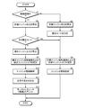
- the PCU 41 When the driving of the vehicle is started, the PCU 41 repeatedly executes output control whose procedure is shown in the flowchart of FIG. 2 at predetermined control intervals (for example, 10 msec). When the output control is started, the PCU 41 determines whether the exhaust purification catalyst 16 is warming up based on a detection signal of an exhaust temperature sensor (not shown) or the like in step S1. If this determination is No, step S2
- the target engine output PEtgt of the engine 2 is calculated by the following equation (1).
- PEdd is the driver's requested engine output obtained based on the detection signal of the accelerator sensor 42
- Pdv is the power consumption of the downverter 34.
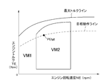
- step S3 the PCU 41 sets the current target engine output PEtgt to the EM valve opening mode on the target operation line (line where the fuel consumption / generated output of the engine 2 is the smallest) in the valve opening mode map of FIG. VM1 (open valve mode to increase intake quantity to raise the temperature of exhaust purification catalyst 16) and fuel consumption open mode VM2 (to improve fuel efficiency, for example, one intake valve 22 is closed to make swirl) It is determined in which of the valve opening modes to be strengthened (in FIG. 4, the fuel consumption valve opening mode VM2 is present).
- step S4 the PCU 41 sets a target engine rotational speed NEtgt and a target engine torque TEtgt from the target engine output PEtgt and the target operation line based on the engine rotational speed-engine torque map of FIG.
- step S5 the PCU 41 drives and controls the engine 2 (that is, the fuel injection valves 24, 28, the spark plug 25, the variable valve mechanism 26, 27, etc.) based on the processing results of steps S3, S4.
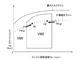
- step S1 determines whether or not the target engine output PEtgt exists in the EM valve opening mode VM1 from the current target engine rotational speed NEtgt and the target engine torque TEtgt based on the valve opening mode map of FIG. 5 in step S7. Determine if Then, if this determination is Yes, the PCU 41 proceeds to steps S4 and S5, and drives and controls the engine 2 in the EM valve opening mode VM1.
- step S8 the PCU 41 shifts to the EM valve opening mode VM1 in step S8, as shown by the arrow in FIG.
- the correction engine output PE 'in which the target engine output PEtgt is reduced along the target operation line is calculated to make the target engine output PEtgt decrease
- step S10 the PCU 41 controls the driving of the fuel injection valves 24, 28 and the spark plug 25 based on the processing result in step S9, and controls the variable valve mechanisms 26, 27 in the EM valve opening mode VM1. Do.
- step S12 the PCU 41 corrects the target engine output PEtgt (that is, the product of the target engine rotational speed NEtgt and the target engine torque TEtgt) and the corrected engine output PE '(that is, the corrected target engine rotational speed NEtgt' and the corrected target engine
- the motor generator 3 (motor 31) is made to perform driving force assist so as to compensate the output fluctuation ⁇ P in step S13. .
- the second embodiment includes the same power unit as the first embodiment described above, but the procedure of output control is different, so only the operation will be described.
- the PCU 41 When the driving of the automobile is started, the PCU 41 repeatedly executes output control whose procedure is shown in the flowchart of FIG. 6 at predetermined control intervals (for example, 10 msec). When the output control is started, the PCU 41 determines whether the exhaust purification catalyst 16 is warming up based on a detection signal of an exhaust temperature sensor (not shown) or the like in step S21. If this determination is No, step S22 The target engine output PEtgt of the engine 2 is calculated by the equation (1) described above.
- step S23 the PCU 41 determines whether the current target engine output PEtgt is present in the EM valve opening mode VM1 or the fuel consumption valve opening mode VM2 based on the valve opening mode map of FIG. 3 described above. .
- step S24 the PCU 41 sets a target engine rotational speed NEtgt and a target engine torque TEtgt from the target engine output PEtgt and the target operation line based on the engine rotational speed-engine torque map of FIG. 4 described above.
- step S25 the PCU 41 drives and controls the engine 2 (that is, the fuel injection valves 24, 28, the spark plug 25, the variable valve mechanism 26, 27, etc.) based on the processing results in steps S23, S24.
- step S21 determines whether or not the target engine output PEtgt is present in the EM valve opening mode VM1 based on the warm-up valve opening mode map of FIG. 7 in step S27. For example, the process proceeds to steps S24 and S25, and drive control of the engine 2 is performed in the fuel consumption valve opening mode VM2.
- step S27 If the target engine output PEtgt is present in the EM valve opening mode VM1 and the determination in step S27 is Yes, then the PCU 41 does not change the engine operating point (engine rotational speed NE) in step S28 and does not change the EM valve opening mode VM1.
- the corrected target engine torque TEtgt' is set in step S29.
- step S30 the PCU 41 controls driving of the fuel injection valves 24, 28 and the spark plug 25 based on the processing result of step S29, and controls driving of the variable valve mechanisms 26, 27 in the EM valve opening mode VM1. Do.
- step S31 the PCU 41 calculates the product of the target engine rotational speed NEtgt and the target engine torque TEtgt) and the corrected engine output PE '(ie, the product of the target engine rotational speed NEtgt and the corrected target engine torque TEtgt').
- step S32 the motor generator 3 (generator 32) charges and discharges the battery 33 to offset the output fluctuation ⁇ P.
- the third embodiment also includes the same power unit as the first embodiment described above, but the procedure of output control is different, so only the operation will be described.
- ⁇ Operation of Third Embodiment
- the PCU 41 When the driving of the vehicle is started, the PCU 41 repeatedly executes output control whose procedure is shown in the flowchart of FIG. 8 at predetermined control intervals (for example, 10 msec).
- the PCU 41 determines whether or not the exhaust purification catalyst 16 is warming up based on a detection signal of an exhaust temperature sensor (not shown) or the like in step S41.
- the target engine output PEtgt of the engine 2 is calculated by the equation (1) described above.
- step S43 the PCU 41 determines whether or not the current target engine output PEtgt exists in the EM valve opening mode VM1 based on the valve opening mode map of FIG. 3 described above. Then, if this determination is Yes, the PCU 41 determines the target engine rotation speed NEtgt and the target engine from the target engine output PEtgt and the target operation line in step S44 based on the engine rotation speed-engine torque map of FIG. Set the torque TEtgt. Thereafter, in step S45, the PCU 41 drives and controls the engine 2 in the EM valve opening mode VM1 based on the processing result in step S44.
- step S43 the PCU 41 sets the EM valve opening mode VM1 in step S46 as indicated by the arrow in FIG. After the correction engine output PE 'in which the target engine output PEtgt is reduced along the target operation line is calculated to make the transition, the correction target engine rotational speed NEtgt' and the correction target engine torque TEtgt 'are set in step S47. Next, in step S48, the PCU 41 controls the driving of the engine 2 in the EM valve opening mode VM1 based on the processing result of step S47.
- step S49 the PCU 41 corrects the engine output PE 'by multiplying the target engine rotational speed NEtgt by the target engine torque TEtgt) (ie, the product of the corrected target engine rotational speed NEtgt' and the corrected target engine torque TEtgt '). Is calculated as the output fluctuation .DELTA.P, and then the battery 33 is charged and discharged from the motor generator 3 (generator 32) in step S50 to offset the output fluctuation .DELTA.P.
- step S41 calculates the target engine output PEtgt of the engine 2 by the equation (1) in step S51.
- the PCU 41 determines whether or not the target engine output PEtgt exists in the fuel consumption valve open mode VM2 from the current target engine rotational speed NEtgt and the target engine torque TEtgt in step S52 based on the valve opening mode map of FIG.
- step S53 the PCU 41 determines the target engine rotation speed NEtgt and the target engine torque TEtgt from the target engine output PEtgt and the target operation line in step S53 based on the engine rotation speed-engine torque map of FIG. And set. Thereafter, in step S54, the PCU 41 controls driving of the engine 2 in the fuel consumption valve open mode VM2 based on the processing result of step S53.
- step S52 When the target engine output PEtgt is present in the EM valve opening mode VM1 and the determination in step S52 is No, the PCU 41 sets the fuel consumption valve opening mode VM2 in step S55 as indicated by an arrow in FIG. After shifting the target engine output PEtgt to increase or decrease the target engine output PEtgt along the target operation line, the corrected target engine rotational speed NEtgt 'and the corrected target engine torque TEtgt' are set in step S56. Next, in step S57, the PCU 41 drives and controls the engine 2 in the fuel consumption valve open mode VM2 based on the processing result in step S56.
- step S58 the PCU 41 corrects the engine output PE 'by multiplying the target engine rotational speed NEtgt by the target engine torque TEtgt) (that is, the product of the corrected target engine rotational speed NEtgt' and the corrected target engine torque TEtgt '). Is calculated as the output fluctuation .DELTA.P, and then the battery 33 is charged and discharged from the motor generator 3 (generator 32) in step S59 to offset the output fluctuation .DELTA.P.
- the engine 2 is operated in the EM valve opening mode VM1 when the exhaust purification catalyst 16 is warmed up by adopting the configuration described above, and harmful exhaust gas components are reduced, and the output fluctuation Since ⁇ P is compensated by the driving power assist of the motor generator 3 and charging / discharging of the battery 33, it can be effectively suppressed that the driver feels a sense of discomfort in the driving feeling and the drivability is lowered.
- the present invention can be widely modified and implemented without being limited to these embodiments.
- the driving force can be assisted by the motor 31 as in the first embodiment.
- the specific configuration of the power unit and the specific procedure of control can be appropriately changed without departing from the spirit of the present invention.
Landscapes
- Engineering & Computer Science (AREA)
- Chemical & Material Sciences (AREA)
- Combustion & Propulsion (AREA)
- Mechanical Engineering (AREA)
- Transportation (AREA)
- Power Engineering (AREA)
- Automation & Control Theory (AREA)
- General Engineering & Computer Science (AREA)
- Hybrid Electric Vehicles (AREA)
- Control Of Vehicle Engines Or Engines For Specific Uses (AREA)
- Output Control And Ontrol Of Special Type Engine (AREA)
- Electric Propulsion And Braking For Vehicles (AREA)
Abstract
運転フィーリングの変化等を伴うことなく触媒暖機運転中における有害排出ガス成分の低減等を実現したハイブリッド車の制御装置を提供する。 ステップS7の判定がNoとなった場合、PCU(41)は、ステップS8で補正エンジン出力PE'を算出した後、ステップS9で補正目標エンジン回転速度NEtgt'および補正目標エンジントルクTEtgt'を設定する。次に、PCU(41)は、ステップS10で、ステップS9の処理結果に基づき燃料噴射弁(24,28)や点火プラグ(25)等を駆動制御するとともに、EM開弁モードVM1で可変動弁機構(26,27)を駆動制御する。次に、PCU41は、ステップS12で目標エンジン出力PEtgtと補正エンジン出力PE'との差を出力変動分ΔPとして算出した後、ステップS13で出力変動分ΔPを補うようにモータジェネレータ(3)(モータ31)に駆動力アシストを行わせる。
Description
本発明は、ハイブリッド車の制御装置に係り、詳しくは、運転フィーリングの変化等を伴うことなく、触媒暖機中における有害排出ガス成分の低減や触媒暖機完了後における燃費の向上を図る技術に関する。
4サイクルガソリンエンジン(以下、単にエンジンと記す)では、出力および燃費の向上や有害排出ガス成分の低減等を図るべく、種々の可変動弁装置を搭載したものが多くなっている。可変動弁装置としては、低速型カムと高速型カムとを用いてカム位相とバルブリフトとを同時に変化させるものが一般的であるが、カム位相可変機構とバルブリフト可変機構とを用いてカム位相とバルブリフトとを個別に可変制御するものも出現している(特許文献1参照)。
可変動弁装置を備えたエンジンでは、始動後に排気ガス浄化触媒(以下、単に触媒と記す)が活性温度となるまでは触媒の昇温に適したバルブ開弁モード(以下、EM開弁モードと記す)で運転し、触媒の暖機が完了した後に燃料消費量を抑えるバルブ開弁モード(以下、燃費開弁モードと記す)で運転することがある。例えば、運転状態に応じて予混合圧縮着火(Homogeneous Charge Compression Ignition:以下、HCCIと記す)と火花点火(Spark Ignition: 以下、SIと記す)とを切り換えるHCCIエンジンにおいて、HCCI(燃費開弁モード)とSIとの間に空気過剰率λを1.0として火花点火を行うTSI(移行期火花点火)を設定し、冷間始動時や触媒暖機時においては、TSIを暖機モードとして本来はHCCIで運転する領域の一部に適用するものが提案されている(特許文献2参照)。
一方、内燃機関と電気モータとを並設し、自動車の走行状況や運転者の意志に応じて、内燃機関と電気モータとの少なくとも一方を走行用動力源として用いるハイブリッド車が出現している(特許文献3参照)。ハイブリッド車には、内燃機関と電気モータとを同時に用いることで高い加速性能や登坂能力を得る、電気モータのみを用いることで燃料消費の低減や夜間走行時における静粛性を実現する、減速時に電気モータを発電機として用いることで走行エネルギを電力エネルギとして回収できる等の種々の特長が存在する。
上述した特許文献2のエンジンでは、触媒の暖機完了時点で内燃機関の運転がTSIからHCCIに移行することで、アクセルペダルの踏込量が同一であるにもかかわらず内燃機関の発生トルクが急変することがあった。これにより、運転者が運転フィーリングに違和感を憶えるとともに、ドライバビリティの低下がもたらされる問題があった。また、本来はHCCIである領域の一部でTSIによる運転が行われるため、HCCIによる有害排出ガス成分の低減効果が得られ難くなる問題もあった。
本発明は、このような背景に鑑みなされたもので、運転フィーリングの変化等を伴うことなく触媒暖機運転中における有害排出ガス成分の低減を実現したハイブリッド車の制御装置を提供することを目的とする。
第1の発明は、第1の走行用駆動源としての内燃機関(2)と、回生ブレーキとしても機能する第2の走行用駆動源としてのモータジェネレータ(3)と、前記内燃機関の吸気バルブ(22)と排気バルブ(23)との少なくとも一方の開弁特性を可変制御する開弁特性可変装置(26,27)と、前記内燃機関の排気ガスを浄化する排気浄化装置(16)と、前記モータジェネレータとの間で電力の授受を行うバッテリ(33)と、運転者の要求エンジン出力を検出する要求エンジン出力検出装置(42)とを有するハイブリッド車の制御装置(41)であって、エンジン回転速度とエンジントルクとをパラメータとして、前記排気ガス中の有害排出ガス成分を抑制するように前記開弁特性可変装置を駆動するEM開弁モード領域と、前記内燃機関の燃料消費量を抑制するように前記開弁特性可変装置を駆動する燃費開弁モード領域と、燃料消費率が最も低くなる目標動作ラインとが設定されたモードマップを有し、前記排気浄化装置の暖機が完了するまでの間、前記要求エンジン出力と前記モードマップの目標動作ラインとからは燃費開弁モードとなる場合の少なくとも一部で前記EM開弁モードにより前記開弁特性可変装置を駆動制御し、前記EM開弁モードの実行によって前記内燃機関の発生出力と前記要求エンジン出力との間に差が生じた場合に、当該出力差を補償するように前記モータジェネレータを作動させる。
また、第2の発明は、第1の発明に係るハイブリッド車の制御装置において、前記排気浄化装置の暖機が完了するまでの間、前記エンジン回転速度および前記エンジントルクを前記目標動作ライン上に設定するとともに、当該エンジン回転速度が前記燃費開弁モードによる運転領域に移行することを禁止する。
また、第3の発明は、第1の発明に係るハイブリッド車の制御装置において、前記排気浄化装置の暖機が完了するまでの間、前記燃費開弁モード領域の一部を暫定的なEM開弁モード領域とし、当該暫定的なEM開弁モード領域においては、前記要求エンジン出力と前記目標動作ラインとによって設定されたエンジン回転速度を変えることなく、前記開弁特性可変装置をEM開弁モードで駆動制御する。
また、第4の発明は、第1~第3の発明に係るハイブリッド車の制御装置において、前記排気浄化装置の暖機完了後は、前記要求エンジン出力と前記モードマップの目標動作ラインとからはEM開弁モードとなる場合の少なくとも一部で前記開弁特性可変装置を前記燃費開弁モードで駆動制御するとともに、当該燃費開弁モードの実行によって前記内燃機関の発生出力と前記要求エンジン出力との間に過不足が生じたときには、当該過不足を補償するように前記モータジェネレータを作動させることを特徴とする。
本発明によれば、排気浄化装置の暖機が完了するまではEM開弁モードで運転されやすくなり、内燃機関からの有害排出ガス成分が減少する一方、EM開弁モードを実行することによる内燃機関の出力減少や出力増大がモータジェネレータによって補償され、運転者が運転フィーリングに違和感を憶え難くなる。また、暖機完了後には内燃機関が燃費開弁モードで運転されやすくするものでは、燃費の向上が実現できる一方、燃費開弁モードを実行することによる内燃機関の出力増減がモータジェネレータをモータまたは回生ブレーキとして作動させることによって補償され、運転者が運転フィーリングに違和感を憶え難くなる。
以下、図面を参照して、本発明を自動車(ハイブリッド車)のパワーユニット制御に適用したいくつかの実施形態を詳細に説明する。
[第1実施形態]
≪第1実施形態の構成≫
図1に示すように、本実施形態のパワーユニット1は、エンジン2と、モータジェネレータ3とから構成されており、ディファレンシャル装置と一体の変速機4を介して図示しない左右前輪に駆動力を与える。
≪第1実施形態の構成≫
図1に示すように、本実施形態のパワーユニット1は、エンジン2と、モータジェネレータ3とから構成されており、ディファレンシャル装置と一体の変速機4を介して図示しない左右前輪に駆動力を与える。
エンジン2は、直列4気筒のHCCIエンジンであり、エアクリーナ11、電動スロットル弁12、サージタンク13、吸気管14等からなる吸気系と、排気マニホールド15、排気浄化触媒16、排気管17等からなる排気系を備えている。エンジン2のシリンダヘッド21には、各気筒ごとに、一対の吸気バルブ22、一対の排気バルブ23、筒内噴射用の燃料噴射弁24、点火プラグ25、吸排気バルブ22,23の開弁特性をそれぞれ変化させる可変動弁機構26,27等が設けられている。また、吸気管14には、各気筒ごとに吸気管噴射用の燃料噴射弁28が設けられている。なお、本実施形態の可変動弁機構26,27は、吸排気バルブ22,23の開弁特性をそれぞれ3段階で切り換えるべく、カム位相およびリフト量が異なる3種のカムを備えている。
モータジェネレータ3は、エンジン2に対する駆動力アシストや電動走行に供されるモータ31、エンジン2の出力や自動車の走行エネルギを電力に変換するジェネレータ32を備えており、図示しない変速機やディファレンシャル装置を介して左右前輪に連結されている。モータジェネレータ3は、自動車の車体後部に搭載されたバッテリ33に接続されており、バッテリ33との間で電力の授受を行う。バッテリ33にはDC-DCコンバータ等からなるダウンバータ34が接続されており、このダウンバータ34によって12Vに降圧された電力が各種電動補機(電動エアコンディショナや電動ウォータポンプ等)や電気装置(灯火類や電気ヒータ等)に供給される。
自動車の車体にはPCU(パワーコントロールユニット)41が搭載されており、このPCU41がエンジン2やモータジェネレータ3を統括制御する。PCU41には、エンジン2やモータジェネレータ3、バッテリ33等からの情報の他、アクセルセンサ42からのアクセルペダル43の踏込量情報(すなわち、運転者の要求エンジン出力)が入力する。
≪第1実施形態の作用≫
自動車の運転が開始されると、PCU41は、図2のフローチャートにその手順を示す出力制御を所定の制御間隔(例えば、10msec)で繰り返し実行する。
出力制御を開始すると、PCU41は、ステップS1で図示しない排気温センサの検出信号等に基づいて排気浄化触媒16が暖機中であるか否かを判定し、この判定がNoであればステップS2でエンジン2の目標エンジン出力PEtgtを下式(1)により算出する。下式において、PEddはアクセルセンサ42の検出信号に基づいて得られた運転者の要求エンジン出力であり、Pdvはダウンバータ34の消費電力である。
PEtgt=PEdd+Pdv・・・・・(1)
自動車の運転が開始されると、PCU41は、図2のフローチャートにその手順を示す出力制御を所定の制御間隔(例えば、10msec)で繰り返し実行する。
出力制御を開始すると、PCU41は、ステップS1で図示しない排気温センサの検出信号等に基づいて排気浄化触媒16が暖機中であるか否かを判定し、この判定がNoであればステップS2でエンジン2の目標エンジン出力PEtgtを下式(1)により算出する。下式において、PEddはアクセルセンサ42の検出信号に基づいて得られた運転者の要求エンジン出力であり、Pdvはダウンバータ34の消費電力である。
PEtgt=PEdd+Pdv・・・・・(1)
次に、PCU41は、ステップS3で、図3の開弁モードマップの目標動作ライン(エンジン2の燃料消費/発生出力が最も小さくなるライン)上で、現在の目標エンジン出力PEtgtがEM開弁モードVM1(排気浄化触媒16を昇温させるために、吸気量を増大させる開弁モード)と燃費開弁モードVM2(燃費を向上させるために、例えば、一方の吸気バルブ22を閉弁させてスワールを強める開弁モード)とのどちらに存在するのか(図4では、燃費開弁モードVM2に存在)を判定する。
次に、PCU41は、ステップS4で、図4のエンジン回転速度-エンジントルクマップに基づき、目標エンジン出力PEtgtと目標動作ラインとから目標エンジン回転速度NEtgtと目標エンジントルクTEtgtとを設定する。しかる後、PCU41は、ステップS5で、ステップS3,S4の処理結果に基づき、エンジン2(すなわち、燃料噴射弁24,28や点火プラグ25、可変動弁機構26,27等)を駆動制御する。
一方、エンジン2の始動直後等でステップS1の判定がYesとなった場合、PCU41は、ステップS6でエンジン2の目標エンジン出力PEtgtを前述の式(1)により算出する。次に、PCU41は、ステップS7で、図5の開弁モードマップに基づき、現在の目標エンジン回転速度NEtgtおよび目標エンジントルクTEtgtから、目標エンジン出力PEtgtがEM開弁モードVM1に存在しているか否かを判定する。そして、この判定がYesであれば、PCU41は、ステップS4,S5に移行してEM開弁モードVM1でエンジン2を駆動制御する。
目標エンジン出力PEtgtが燃費開弁モードVM2に存在していてステップS7の判定がNoとなった場合、PCU41は、ステップS8で、図5中に矢印で示すように、EM開弁モードVM1に移行させるべく、目標エンジン出力PEtgtを目標動作ラインに沿って低減させた補正エンジン出力PE'を算出した後、ステップS9で補正目標エンジン回転速度NEtgt'および補正目標エンジントルクTEtgt'を設定する。次に、PCU41は、ステップS10で、ステップS9の処理結果に基づき燃料噴射弁24,28や点火プラグ25等を駆動制御するとともに、EM開弁モードVM1で可変動弁機構26,27を駆動制御する。
次に、PCU41は、ステップS12で目標エンジン出力PEtgt(すなわち、目標エンジン回転速度NEtgtと目標エンジントルクTEtgtとの積)と補正エンジン出力PE'(すなわち、補正目標エンジン回転速度NEtgt'と補正目標エンジントルクTEtgt'との積)との差を出力変動分ΔP(出力不足分)として算出した後、ステップS13で出力変動分ΔPを補うようにモータジェネレータ3(モータ31)に駆動力アシストを行わせる。
[第2実施形態]
第2実施形態は、上述した第1実施形態と同一のパワーユニットを備えているが、出力制御の手順が異なっているため、その作用のみを説明する。
第2実施形態は、上述した第1実施形態と同一のパワーユニットを備えているが、出力制御の手順が異なっているため、その作用のみを説明する。
≪第2実施形態の作用≫
自動車の運転が開始されると、PCU41は、図6のフローチャートにその手順を示す出力制御を所定の制御間隔(例えば、10msec)で繰り返し実行する。
出力制御を開始すると、PCU41は、ステップS21で図示しない排気温センサの検出信号等に基づいて排気浄化触媒16が暖機中であるか否かを判定し、この判定がNoであればステップS22でエンジン2の目標エンジン出力PEtgtを前述の式(1)により算出する。
自動車の運転が開始されると、PCU41は、図6のフローチャートにその手順を示す出力制御を所定の制御間隔(例えば、10msec)で繰り返し実行する。
出力制御を開始すると、PCU41は、ステップS21で図示しない排気温センサの検出信号等に基づいて排気浄化触媒16が暖機中であるか否かを判定し、この判定がNoであればステップS22でエンジン2の目標エンジン出力PEtgtを前述の式(1)により算出する。
次に、PCU41は、ステップS23で、前述した図3の開弁モードマップに基づき、現在の目標エンジン出力PEtgtがEM開弁モードVM1と燃費開弁モードVM2とのどちらに存在するのかを判定する。
次に、PCU41は、ステップS24で、前述した図4のエンジン回転速度-エンジントルクマップに基づき、目標エンジン出力PEtgtと目標動作ラインとから目標エンジン回転速度NEtgtと目標エンジントルクTEtgtとを設定する。しかる後、PCU41は、ステップS25で、ステップS23,S24の処理結果に基づき、エンジン2(すなわち、燃料噴射弁24,28や点火プラグ25、可変動弁機構26,27等)を駆動制御する。
一方、エンジン2の始動直後等でステップS21の判定がYesとなった場合、PCU41は、ステップS26でエンジン2の目標エンジン出力PEtgtを前述の式(1)により算出する。次に、PCU41は、ステップS27で、図7の暖機時開弁モードマップに基づき、目標エンジン出力PEtgtがEM開弁モードVM1に存在しているか否かを判定し、この判定がNoであればステップS24,S25に移行して燃費開弁モードVM2でエンジン2を駆動制御する。
目標エンジン出力PEtgtがEM開弁モードVM1に存在していてステップS27の判定がYesになると、PCU41は、ステップS28で、エンジン動作点(エンジン回転速度NE)を変えずにEM開弁モードVM1でエンジン2を運転する場合のエンジン出力を補正エンジン出力PE'として算出した後、ステップS29で補正目標エンジントルクTEtgt'を設定する。次に、PCU41は、ステップS30で、ステップS29の処理結果に基づき燃料噴射弁24,28や点火プラグ25等を駆動制御するとともに、EM開弁モードVM1で可変動弁機構26,27を駆動制御する。
次に、PCU41は、ステップS31で目標エンジン回転速度NEtgtと目標エンジントルクTEtgtとの積)と補正エンジン出力PE'(すなわち、目標エンジン回転速度NEtgtと補正目標エンジントルクTEtgt'との積)との差を出力変動分ΔPとして算出した後、ステップS32でモータジェネレータ3(ジェネレータ32)からバッテリ33に充放電を行わせて出力変動分ΔPを相殺させる。
[第3実施形態]
第3実施形態も、上述した第1実施形態と同一のパワーユニットを備えているが、出力制御の手順が異なっているため、その作用のみを説明する。
≪第3実施形態の作用≫
自動車の運転が開始されると、PCU41は、図8のフローチャートにその手順を示す出力制御を所定の制御間隔(例えば、10msec)で繰り返し実行する。
出力制御を開始すると、PCU41は、ステップS41で図示しない排気温センサの検出信号等に基づいて排気浄化触媒16が暖機中であるか否かを判定し、この判定がYesであればステップS42でエンジン2の目標エンジン出力PEtgtを前述の式(1)により算出する。
第3実施形態も、上述した第1実施形態と同一のパワーユニットを備えているが、出力制御の手順が異なっているため、その作用のみを説明する。
≪第3実施形態の作用≫
自動車の運転が開始されると、PCU41は、図8のフローチャートにその手順を示す出力制御を所定の制御間隔(例えば、10msec)で繰り返し実行する。
出力制御を開始すると、PCU41は、ステップS41で図示しない排気温センサの検出信号等に基づいて排気浄化触媒16が暖機中であるか否かを判定し、この判定がYesであればステップS42でエンジン2の目標エンジン出力PEtgtを前述の式(1)により算出する。
次に、PCU41は、ステップS43で、前述した図3の開弁モードマップに基づき、現在の目標エンジン出力PEtgtがEM開弁モードVM1に存在するか否かを判定する。そして、この判定がYesであれば、PCU41は、ステップS44で、前述した図4のエンジン回転速度-エンジントルクマップに基づき、目標エンジン出力PEtgtと目標動作ラインとから目標エンジン回転速度NEtgtと目標エンジントルクTEtgtとを設定する。しかる後、PCU41は、ステップS45で、ステップS44の処理結果に基づき、エンジン2をEM開弁モードVM1で駆動制御する。
また、目標エンジン出力PEtgtが燃費開弁モードVM2に存在していてステップS43の判定がNoとなった場合、PCU41は、ステップS46で図5中に矢印で示すように、EM開弁モードVM1に移行させるべく、目標エンジン出力PEtgtを目標動作ラインに沿って低減させた補正エンジン出力PE'を算出した後、ステップS47で補正目標エンジン回転速度NEtgt'および補正目標エンジントルクTEtgt'を設定する。次に、PCU41は、ステップS48で、ステップS47の処理結果に基づきエンジン2をEM開弁モードVM1で駆動制御する。
次に、PCU41は、ステップS49で目標エンジン回転速度NEtgtと目標エンジントルクTEtgtとの積)と補正エンジン出力PE'(すなわち、補正目標エンジン回転速度NEtgt'と補正目標エンジントルクTEtgt'との積)との差を出力変動分ΔPとして算出した後、ステップS50でモータジェネレータ3(ジェネレータ32)からバッテリ33に充放電を行わせて出力変動分ΔPを相殺させる。
一方、排気浄化触媒16の暖機が終了してステップS41の判定がNoとなった場合、PCU41は、ステップS51でエンジン2の目標エンジン出力PEtgtを式(1)により算出する。次に、PCU41は、ステップS52で、図5の開弁モードマップに基づき、現在の目標エンジン回転速度NEtgtおよび目標エンジントルクTEtgtから、目標エンジン出力PEtgtが燃費開弁モードVM2に存在しているか否かを判定する。そして、この判定がYesであれば、PCU41は、ステップS53で、図4のエンジン回転速度-エンジントルクマップに基づき、目標エンジン出力PEtgtと目標動作ラインとから目標エンジン回転速度NEtgtと目標エンジントルクTEtgtとを設定する。しかる後、PCU41は、ステップS54で、ステップS53の処理結果に基づき、エンジン2を燃費開弁モードVM2で駆動制御する。
また、目標エンジン出力PEtgtがEM開弁モードVM1に存在していてステップS52の判定がNoとなった場合、PCU41は、ステップS55で図9中に矢印で示すように、燃費開弁モードVM2に移行させるべく、目標エンジン出力PEtgtを目標動作ラインに沿って増減させた補正エンジン出力PE'を算出した後、ステップS56で補正目標エンジン回転速度NEtgt'および補正目標エンジントルクTEtgt'を設定する。次に、PCU41は、ステップS57で、ステップS56の処理結果に基づきエンジン2を燃費開弁モードVM2で駆動制御する。
次に、PCU41は、ステップS58で目標エンジン回転速度NEtgtと目標エンジントルクTEtgtとの積)と補正エンジン出力PE'(すなわち、補正目標エンジン回転速度NEtgt'と補正目標エンジントルクTEtgt'との積)との差を出力変動分ΔPとして算出した後、ステップS59でモータジェネレータ3(ジェネレータ32)からバッテリ33に充放電を行わせて出力変動分ΔPを相殺させる。
各実施形態では、上述した構成を採ったことにより、排気浄化触媒16の暖機時においては、エンジン2がEM開弁モードVM1で運転されて有害排出ガス成分が削減されるとともに、出力変動分ΔPがモータジェネレータ3の駆動力アシストやバッテリ33への充放電によって補われることで運転者が運転フィーリングに違和感を憶えることや、ドライバビリティが低下することが効果的に抑制できるようになる。
以上で具体的実施形態の説明を終えるが、本発明はこれら実施形態に限定されることなく幅広く変形実施することができる。例えば、第2,第3実施形態においてバッテリ33に余裕が存在すれば、第1実施形態と同様にモータ31に駆動力アシストを行わせることができる。その他、パワーユニットの具体的構成や制御の具体的手順等についても、本発明の趣旨を逸脱しない範囲であれば適宜変更可能である。
1 パワーユニット
2 エンジン
3 モータジェネレータ
16 排気浄化触媒
22 吸気バルブ
23 排気バルブ
26,27 可変動弁機構(開弁特性可変装置)
31 モータ
32 ジェネレータ
33 バッテリ
34 ダウンバータ
41 PCU(制御装置)
42 アクセルセンサ(要求エンジン出力検出装置)
2 エンジン
3 モータジェネレータ
16 排気浄化触媒
22 吸気バルブ
23 排気バルブ
26,27 可変動弁機構(開弁特性可変装置)
31 モータ
32 ジェネレータ
33 バッテリ
34 ダウンバータ
41 PCU(制御装置)
42 アクセルセンサ(要求エンジン出力検出装置)
Claims (4)
- 第1の走行用駆動源としての内燃機関と、回生ブレーキとしても機能する第2の走行用駆動源としてのモータジェネレータと、前記内燃機関の吸気バルブと排気バルブとの少なくとも一方の開弁特性を可変制御する開弁特性可変装置と、前記内燃機関の排気ガスを浄化する排気浄化装置と、前記モータジェネレータとの間で電力の授受を行うバッテリと、運転者の要求エンジン出力を検出する要求エンジン出力検出装置とを有するハイブリッド車の制御装置であって、
エンジン回転速度とエンジントルクとをパラメータとして、前記排気ガス中の有害排出ガス成分を抑制するように前記開弁特性可変装置を駆動するEM開弁モード領域と、前記内燃機関の燃料消費量を抑制するように前記開弁特性可変装置を駆動する燃費開弁モード領域と、燃料消費率が最も低くなる目標動作ラインとが設定されたモードマップを有し、
前記排気浄化装置の暖機が完了するまでの間、前記要求エンジン出力と前記モードマップの目標動作ラインとからは燃費開弁モードとなる場合の少なくとも一部で前記EM開弁モードにより前記開弁特性可変装置を駆動制御し、
前記EM開弁モードの実行によって前記内燃機関の発生出力と前記要求エンジン出力との間に差が生じた場合に、当該出力差を補償するように前記モータジェネレータを作動させることを特徴とするハイブリッド車の制御装置。 - 前記排気浄化装置の暖機が完了するまでの間、前記エンジン回転速度および前記エンジントルクを前記目標動作ライン上に設定するとともに、当該エンジン回転速度が前記燃費開弁モードによる運転領域に移行することを禁止することを特徴とする、請求項1に記載されたハイブリッド車の制御装置。
- 前記排気浄化装置の暖機が完了するまでの間、前記燃費開弁モード領域の一部を暫定的なEM開弁モード領域とし、当該暫定的なEM開弁モード領域においては、前記要求エンジン出力と前記目標動作ラインとによって設定されたエンジン回転速度を変えることなく、前記開弁特性可変装置をEM開弁モードで駆動制御することを特徴とする、請求項1に記載されたハイブリッド車の制御装置。
- 前記排気浄化装置の暖機完了後は、前記要求エンジン出力と前記モードマップの目標動作ラインとからはEM開弁モードとなる場合の少なくとも一部で前記開弁特性可変装置を前記燃費開弁モードで駆動制御するとともに、当該燃費開弁モードの実行によって前記内燃機関の発生出力と前記要求エンジン出力との間に過不足が生じたときには、当該過不足を補償するように前記モータジェネレータを作動させることを特徴とする、請求項1~請求項3のいずれか一項に記載されたハイブリッド車の制御装置。
Priority Applications (1)
| Application Number | Priority Date | Filing Date | Title |
|---|---|---|---|
| JP2012502997A JP5584282B2 (ja) | 2010-03-02 | 2011-02-23 | ハイブリッド車の制御装置 |
Applications Claiming Priority (2)
| Application Number | Priority Date | Filing Date | Title |
|---|---|---|---|
| JP2010045084 | 2010-03-02 | ||
| JP2010-045084 | 2010-03-02 |
Publications (1)
| Publication Number | Publication Date |
|---|---|
| WO2011108226A1 true WO2011108226A1 (ja) | 2011-09-09 |
Family
ID=44541896
Family Applications (1)
| Application Number | Title | Priority Date | Filing Date |
|---|---|---|---|
| PCT/JP2011/001016 WO2011108226A1 (ja) | 2010-03-02 | 2011-02-23 | ハイブリッド車の制御装置 |
Country Status (2)
| Country | Link |
|---|---|
| JP (1) | JP5584282B2 (ja) |
| WO (1) | WO2011108226A1 (ja) |
Cited By (2)
| Publication number | Priority date | Publication date | Assignee | Title |
|---|---|---|---|---|
| WO2014162186A1 (en) * | 2013-04-03 | 2014-10-09 | Toyota Jidosha Kabushiki Kaisha | Hybrid vehicle and control method therefor |
| WO2015092509A1 (en) * | 2013-12-19 | 2015-06-25 | Toyota Jidosha Kabushiki Kaisha | Hybrid vehicle, controller for hybrid vehicle, and control method for hybrid vehicle for warming-up of a catalyst in avoiding power loss when required |
Citations (4)
| Publication number | Priority date | Publication date | Assignee | Title |
|---|---|---|---|---|
| JPH09329060A (ja) * | 1996-06-10 | 1997-12-22 | Toyota Motor Corp | ハイブリッド型車両の触媒温度制御装置 |
| JP3936901B2 (ja) * | 2001-09-25 | 2007-06-27 | アー・ファウ・エル・リスト・ゲー・エム・ベー・ハー | 内燃機関と内燃機関制御方法 |
| JP2008163768A (ja) * | 2006-12-27 | 2008-07-17 | Honda Motor Co Ltd | 開弁特性可変型内燃機関 |
| JP2009292287A (ja) * | 2008-06-04 | 2009-12-17 | Honda Motor Co Ltd | ハイブリッド車両の制御装置 |
-
2011
- 2011-02-23 JP JP2012502997A patent/JP5584282B2/ja not_active Expired - Fee Related
- 2011-02-23 WO PCT/JP2011/001016 patent/WO2011108226A1/ja active Application Filing
Patent Citations (4)
| Publication number | Priority date | Publication date | Assignee | Title |
|---|---|---|---|---|
| JPH09329060A (ja) * | 1996-06-10 | 1997-12-22 | Toyota Motor Corp | ハイブリッド型車両の触媒温度制御装置 |
| JP3936901B2 (ja) * | 2001-09-25 | 2007-06-27 | アー・ファウ・エル・リスト・ゲー・エム・ベー・ハー | 内燃機関と内燃機関制御方法 |
| JP2008163768A (ja) * | 2006-12-27 | 2008-07-17 | Honda Motor Co Ltd | 開弁特性可変型内燃機関 |
| JP2009292287A (ja) * | 2008-06-04 | 2009-12-17 | Honda Motor Co Ltd | ハイブリッド車両の制御装置 |
Cited By (5)
| Publication number | Priority date | Publication date | Assignee | Title |
|---|---|---|---|---|
| WO2014162186A1 (en) * | 2013-04-03 | 2014-10-09 | Toyota Jidosha Kabushiki Kaisha | Hybrid vehicle and control method therefor |
| CN105102290A (zh) * | 2013-04-03 | 2015-11-25 | 丰田自动车株式会社 | 混合动力车辆及其控制方法 |
| US9476335B2 (en) | 2013-04-03 | 2016-10-25 | Toyota Jidosha Kabushiki Kaisha | Hybrid vehicle and control method therefor |
| CN105102290B (zh) * | 2013-04-03 | 2017-04-26 | 丰田自动车株式会社 | 混合动力车辆及其控制方法 |
| WO2015092509A1 (en) * | 2013-12-19 | 2015-06-25 | Toyota Jidosha Kabushiki Kaisha | Hybrid vehicle, controller for hybrid vehicle, and control method for hybrid vehicle for warming-up of a catalyst in avoiding power loss when required |
Also Published As
| Publication number | Publication date |
|---|---|
| JPWO2011108226A1 (ja) | 2013-06-20 |
| JP5584282B2 (ja) | 2014-09-03 |
Similar Documents
| Publication | Publication Date | Title |
|---|---|---|
| CN108688647B (zh) | 汽车、汽车用的控制装置及汽车的控制方法 | |
| JP6070591B2 (ja) | ハイブリッド車両およびハイブリッド車両の制御方法 | |
| JP4535184B2 (ja) | ハイブリッド車両の制御装置 | |
| JP4519085B2 (ja) | 内燃機関の制御装置 | |
| JP4301197B2 (ja) | 車両の制御装置 | |
| JP6926656B2 (ja) | ハイブリッド車両の制御装置 | |
| JP6380448B2 (ja) | ハイブリッド車両 | |
| JP6852802B2 (ja) | ハイブリッド車両の制御方法および制御装置 | |
| JP2013129260A (ja) | ハイブリッド自動車 | |
| CN105829686A (zh) | 具有与可变进气门正时相关的两级催化剂预热的混合动力车辆、混合动力车辆的控制器及混合动力车辆的控制方法 | |
| JP4582184B2 (ja) | 車両の制御装置および制御方法 | |
| JP2014092066A (ja) | Egrバルブ故障検出装置 | |
| JP4752919B2 (ja) | エンジンの制御装置 | |
| JP2009262753A (ja) | ハイブリッド自動車およびその制御方法 | |
| CN113513431A (zh) | 发动机装置及具备该发动机装置的混合动力汽车 | |
| JP4479110B2 (ja) | エンジン自動始動用の制御装置と制御方法 | |
| WO2011108226A1 (ja) | ハイブリッド車の制御装置 | |
| JP5126023B2 (ja) | 内燃機関装置、それを搭載した車両および内燃機関装置の制御方法 | |
| JP2003164013A (ja) | 車両の駆動力制御方法とその制御装置 | |
| JP5520641B2 (ja) | 内燃機関の制御装置 | |
| JP2014189081A (ja) | ハイブリッド自動車 | |
| JP4211243B2 (ja) | 充電制御装置 | |
| JP5994312B2 (ja) | ハイブリッド車両の制御装置 | |
| JP5736920B2 (ja) | ハイブリッド車のエンジン制御装置 | |
| JP2008286003A (ja) | 車両の運転制御装置 |
Legal Events
| Date | Code | Title | Description |
|---|---|---|---|
| 121 | Ep: the epo has been informed by wipo that ep was designated in this application |
Ref document number: 11750340 Country of ref document: EP Kind code of ref document: A1 |
|
| WWE | Wipo information: entry into national phase |
Ref document number: 2012502997 Country of ref document: JP |
|
| NENP | Non-entry into the national phase |
Ref country code: DE |
|
| 122 | Ep: pct application non-entry in european phase |
Ref document number: 11750340 Country of ref document: EP Kind code of ref document: A1 |