WO2011108170A1 - ステージ装置 - Google Patents
ステージ装置 Download PDFInfo
- Publication number
- WO2011108170A1 WO2011108170A1 PCT/JP2010/072858 JP2010072858W WO2011108170A1 WO 2011108170 A1 WO2011108170 A1 WO 2011108170A1 JP 2010072858 W JP2010072858 W JP 2010072858W WO 2011108170 A1 WO2011108170 A1 WO 2011108170A1
- Authority
- WO
- WIPO (PCT)
- Prior art keywords
- linear motor
- movable table
- movable
- stage apparatus
- stator
- Prior art date
- Legal status (The legal status is an assumption and is not a legal conclusion. Google has not performed a legal analysis and makes no representation as to the accuracy of the status listed.)
- Ceased
Links
Images




Classifications
-
- H—ELECTRICITY
- H10—SEMICONDUCTOR DEVICES; ELECTRIC SOLID-STATE DEVICES NOT OTHERWISE PROVIDED FOR
- H10P—GENERIC PROCESSES OR APPARATUS FOR THE MANUFACTURE OR TREATMENT OF DEVICES COVERED BY CLASS H10
- H10P76/00—Manufacture or treatment of masks on semiconductor bodies, e.g. by lithography or photolithography
- H10P76/20—Manufacture or treatment of masks on semiconductor bodies, e.g. by lithography or photolithography of masks comprising organic materials
- H10P76/204—Manufacture or treatment of masks on semiconductor bodies, e.g. by lithography or photolithography of masks comprising organic materials of organic photoresist masks
- H10P76/2041—Photolithographic processes
-
- G—PHYSICS
- G03—PHOTOGRAPHY; CINEMATOGRAPHY; ANALOGOUS TECHNIQUES USING WAVES OTHER THAN OPTICAL WAVES; ELECTROGRAPHY; HOLOGRAPHY
- G03F—PHOTOMECHANICAL PRODUCTION OF TEXTURED OR PATTERNED SURFACES, e.g. FOR PRINTING, FOR PROCESSING OF SEMICONDUCTOR DEVICES; MATERIALS THEREFOR; ORIGINALS THEREFOR; APPARATUS SPECIALLY ADAPTED THEREFOR
- G03F7/00—Photomechanical, e.g. photolithographic, production of textured or patterned surfaces, e.g. printing surfaces; Materials therefor, e.g. comprising photoresists; Apparatus specially adapted therefor
- G03F7/70—Microphotolithographic exposure; Apparatus therefor
- G03F7/70691—Handling of masks or workpieces
- G03F7/70758—Drive means, e.g. actuators, motors for long- or short-stroke modules or fine or coarse driving
-
- G—PHYSICS
- G03—PHOTOGRAPHY; CINEMATOGRAPHY; ANALOGOUS TECHNIQUES USING WAVES OTHER THAN OPTICAL WAVES; ELECTROGRAPHY; HOLOGRAPHY
- G03F—PHOTOMECHANICAL PRODUCTION OF TEXTURED OR PATTERNED SURFACES, e.g. FOR PRINTING, FOR PROCESSING OF SEMICONDUCTOR DEVICES; MATERIALS THEREFOR; ORIGINALS THEREFOR; APPARATUS SPECIALLY ADAPTED THEREFOR
- G03F7/00—Photomechanical, e.g. photolithographic, production of textured or patterned surfaces, e.g. printing surfaces; Materials therefor, e.g. comprising photoresists; Apparatus specially adapted therefor
- G03F7/70—Microphotolithographic exposure; Apparatus therefor
- G03F7/70691—Handling of masks or workpieces
-
- G—PHYSICS
- G03—PHOTOGRAPHY; CINEMATOGRAPHY; ANALOGOUS TECHNIQUES USING WAVES OTHER THAN OPTICAL WAVES; ELECTROGRAPHY; HOLOGRAPHY
- G03F—PHOTOMECHANICAL PRODUCTION OF TEXTURED OR PATTERNED SURFACES, e.g. FOR PRINTING, FOR PROCESSING OF SEMICONDUCTOR DEVICES; MATERIALS THEREFOR; ORIGINALS THEREFOR; APPARATUS SPECIALLY ADAPTED THEREFOR
- G03F7/00—Photomechanical, e.g. photolithographic, production of textured or patterned surfaces, e.g. printing surfaces; Materials therefor, e.g. comprising photoresists; Apparatus specially adapted therefor
- G03F7/70—Microphotolithographic exposure; Apparatus therefor
- G03F7/70691—Handling of masks or workpieces
- G03F7/70716—Stages
-
- G—PHYSICS
- G03—PHOTOGRAPHY; CINEMATOGRAPHY; ANALOGOUS TECHNIQUES USING WAVES OTHER THAN OPTICAL WAVES; ELECTROGRAPHY; HOLOGRAPHY
- G03F—PHOTOMECHANICAL PRODUCTION OF TEXTURED OR PATTERNED SURFACES, e.g. FOR PRINTING, FOR PROCESSING OF SEMICONDUCTOR DEVICES; MATERIALS THEREFOR; ORIGINALS THEREFOR; APPARATUS SPECIALLY ADAPTED THEREFOR
- G03F7/00—Photomechanical, e.g. photolithographic, production of textured or patterned surfaces, e.g. printing surfaces; Materials therefor, e.g. comprising photoresists; Apparatus specially adapted therefor
- G03F7/70—Microphotolithographic exposure; Apparatus therefor
- G03F7/70691—Handling of masks or workpieces
- G03F7/70716—Stages
- G03F7/70725—Stages control
-
- G—PHYSICS
- G03—PHOTOGRAPHY; CINEMATOGRAPHY; ANALOGOUS TECHNIQUES USING WAVES OTHER THAN OPTICAL WAVES; ELECTROGRAPHY; HOLOGRAPHY
- G03F—PHOTOMECHANICAL PRODUCTION OF TEXTURED OR PATTERNED SURFACES, e.g. FOR PRINTING, FOR PROCESSING OF SEMICONDUCTOR DEVICES; MATERIALS THEREFOR; ORIGINALS THEREFOR; APPARATUS SPECIALLY ADAPTED THEREFOR
- G03F7/00—Photomechanical, e.g. photolithographic, production of textured or patterned surfaces, e.g. printing surfaces; Materials therefor, e.g. comprising photoresists; Apparatus specially adapted therefor
- G03F7/70—Microphotolithographic exposure; Apparatus therefor
- G03F7/708—Construction of apparatus, e.g. environment aspects, hygiene aspects or materials
- G03F7/70808—Construction details, e.g. housing, load-lock, seals or windows for passing light in or out of apparatus
- G03F7/70816—Bearings
-
- H—ELECTRICITY
- H10—SEMICONDUCTOR DEVICES; ELECTRIC SOLID-STATE DEVICES NOT OTHERWISE PROVIDED FOR
- H10P—GENERIC PROCESSES OR APPARATUS FOR THE MANUFACTURE OR TREATMENT OF DEVICES COVERED BY CLASS H10
- H10P72/00—Handling or holding of wafers, substrates or devices during manufacture or treatment thereof
- H10P72/30—Handling or holding of wafers, substrates or devices during manufacture or treatment thereof for conveying, e.g. between different workstations
- H10P72/32—Handling or holding of wafers, substrates or devices during manufacture or treatment thereof for conveying, e.g. between different workstations between different workstations
- H10P72/3202—Mechanical details, e.g. rollers or belts
-
- H—ELECTRICITY
- H10—SEMICONDUCTOR DEVICES; ELECTRIC SOLID-STATE DEVICES NOT OTHERWISE PROVIDED FOR
- H10P—GENERIC PROCESSES OR APPARATUS FOR THE MANUFACTURE OR TREATMENT OF DEVICES COVERED BY CLASS H10
- H10P72/00—Handling or holding of wafers, substrates or devices during manufacture or treatment thereof
- H10P72/30—Handling or holding of wafers, substrates or devices during manufacture or treatment thereof for conveying, e.g. between different workstations
- H10P72/32—Handling or holding of wafers, substrates or devices during manufacture or treatment thereof for conveying, e.g. between different workstations between different workstations
- H10P72/3216—Handling or holding of wafers, substrates or devices during manufacture or treatment thereof for conveying, e.g. between different workstations between different workstations using a general scheme of a conveying path within a factory
Definitions
- the present invention relates to a stage apparatus, and more particularly to a stage apparatus that moves a sample in a predetermined direction in a horizontal plane by a linear motor.
- a stage apparatus that moves a sample in a predetermined direction in a horizontal plane by a linear motor is known.
- a stage apparatus for moving a sample in a predetermined direction in a horizontal plane by such a linear motor is disclosed in, for example, Japanese Patent Application Laid-Open No. 2001-102279.
- Japanese Patent Application Laid-Open No. 2001-102279 includes a reticle fine movement stage (movable table) that holds a reticle (sample) and is finely driven in a horizontal plane, and a reticle coarse movement stage disposed below the reticle fine movement stage.
- a reticle stage stage apparatus
- the reticle coarse movement stage is driven with a larger movement amount than the reticle fine movement stage in the Y-axis direction in the horizontal plane.
- the reticle stage disclosed in Japanese Patent Laid-Open No. 2001-102279 is provided with a pair of linear motors for driving the reticle coarse movement stage in the Y-axis direction.
- the pair of linear motors are arranged outside the reticle coarse movement stage so as to sandwich the reticle coarse movement stage.
- Japanese Patent Laid-Open No. 2001-102279 a linear motor for moving the reticle (sample) in the Y-axis direction in the horizontal plane is arranged outside the reticle coarse movement stage so as to sandwich the reticle coarse movement stage.
- the arrangement space for the linear motor is required outside the arrangement space for the reticle coarse movement stage, and there is a disadvantage that the reticle stage (stage device) is increased in size.
- Japanese Patent Laid-Open No. 2001-102279 has a problem that it is difficult to reduce the size of the stage device (reticle stage).
- the present invention has been made to solve the above-described problems, and one object of the present invention is to provide a stage apparatus that can be miniaturized.
- a stage apparatus includes a movable table for holding a sample, a floating unit movable element and a floating unit stator, and moves the movable table at least in the vertical direction. And a linear motor movable element arranged inside the movable table and a linear motor stator arranged inside the movable table for operating the movable table in the first horizontal direction in the horizontal plane. And a linear motor.
- the linear motor for operating the movable table in the first horizontal direction in the horizontal plane is provided, and the linear motor movable element and the linear motor stator of the linear motor are provided.
- the linear motor arrangement space is provided outside the movable table arrangement space. Since this is not necessary, the horizontal dimension of the stage device can be reduced accordingly. As a result, the stage device can be miniaturized.
- FIG. 3 is a cross-sectional view taken along line 300-300 in FIG. It is a top view which shows the movable table of the stage apparatus by 1st Embodiment of this invention. It is a top view which shows the stage apparatus by 1st Embodiment of this invention.
- FIG. 10 is a sectional view taken along line 400-400 in FIG.
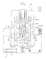
- the magnetic levitation table apparatus 100 is used in an exposure apparatus that develops a circuit pattern on a semiconductor substrate. 1 and 2, the magnetic levitation table device 100 includes a stage device 1, a stage device vibration isolation table 2 that supports the stage device 1, and a laser interferometer vibration isolation table 3. ing.
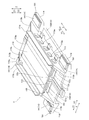
- the stage apparatus 1 includes a movable table 11, a stage fixing unit 12 that surrounds the X direction and the Y direction of the movable table 11, and a position above the movable table 11 (Z1 direction).
- the fixed frame 13 provided is included.
- the stage apparatus 1 includes a magnetic levitation unit 14 having a function of operating the movable table 11 in the X direction and the Z direction, and a linear motor 15 having a function of operating the movable table 11 in the Y direction.
- the stage device 1 is disposed on the upper surface of the stage device vibration isolation table 2.
- the stage fixing portion 12 is an example of the “stator support member” in the present invention
- the magnetic levitation unit 14 is an example of the “levitation unit” in the present invention.
- the movable table 11 has a function of holding a mask (photomask) 16 (see FIG. 4) for transferring a circuit pattern on the lower surface. Further, as will be described later, the movable table 11 includes an X direction in the horizontal plane, a Y direction orthogonal to the X direction in the horizontal plane, a vertical direction (Z direction), a direction around the X axis ( ⁇ x), and a direction around the Y axis ( ⁇ y ) And the Z-axis rotation direction ( ⁇ z). That is, the movable table 11 is configured to be controllable with six degrees of freedom. Thereby, the mask 16 held on the lower surface of the movable table 11 can be moved with six degrees of freedom.
- the mask 16 is an example of the “sample” in the present invention.
- the movable table 11 is orthogonal to the horizontal partition 111 at the horizontal partition 111 extending in the X direction and the center of the horizontal partition 111 in the X direction when viewed from the Y direction.
- a pair of side wall portions 113 are provided at both ends in the X direction of the horizontal partition portion 111.
- flange portions 114 projecting outward in the X direction are formed on the outer surfaces of the lower portions of the pair of side wall portions 113.
- the horizontal partition part 111, the vertical partition part 112, the side wall part 113, and the flange part 114 consist of a lightweight and high specific rigidity ceramic member, and are integrally formed.
- the movable part main frame of this invention is comprised by the horizontal partition part 111, the vertical partition part 112, the side wall part 113, and the flange part 114.
- FIG. The flange portion 114 is an example of the “projecting portion” in the present invention.
- the horizontal partition 111 has a flat plate shape arranged horizontally as shown in FIG. Further, the horizontal partition 111 is formed to extend in the Y direction. Further, the vertical partition 112 has a flat plate shape arranged vertically. Further, the vertical partition 112 is formed to extend in the Y direction. Moreover, the horizontal partition part 111 and the vertical partition part 112 are arrange
- the movable table 11 is configured such that the center of gravity is located at the intersection of the horizontal partition 111 and the vertical partition 112, as will be described later.
- the pair of side wall portions 113 has a flat plate shape arranged vertically, and is arranged in parallel to the vertical partition portion 112.
- the pair of side wall portions 113 are formed to extend in the Y direction.
- the side wall 113 is formed with a plurality of openings 113a. Thereby, the side wall part 113 can be made lightweight and the movable table 11 can be reduced in weight.
- the pair of side wall portions 113 are provided with inclined portions 113b whose upper portions are inclined obliquely outward and downward at both end portions in the Y direction when viewed from the X direction.
- two flange portions 114 are provided on each of the pair of side wall portions 113. That is, two flange portions 114 projecting in the X1 direction side are provided on the outer surface (surface on the X1 direction side) of the side wall portion 113 in the X1 direction, and the outer surface (surface on the X2 direction side) of the side wall portion 113 in the X2 direction. ) Are provided with two flange portions 114 projecting in the X2 direction side. In addition, the two flange portions 114 in the X1 direction (X2 direction) are disposed in the vicinity of both ends in the Y direction of the side wall portion 113 in the X1 direction (X2 direction).
- the four flange parts 114 are provided in the lower part of the side wall part 113, as shown in FIG. Specifically, the upper surfaces 114a (surfaces in the Z1 direction) of the four flange portions 114 are horizontally formed, and in the vertical direction (Z direction), the horizontal partition 111 and the vertical position where the center of gravity of the movable table 11 is located. It is arranged at substantially the same height as the intersection part of the partition part 112.
- the flange portion 114 has a shape in which the height in the vertical direction gradually increases from the outside toward the root portion. That is, the lower surface 114b of the flange portion 114 is formed in an inclined surface shape that is inclined obliquely downward from the outside toward the root portion.
- a lower frame 115 is provided below the vertical partition 112 and the pair of side walls 113, and an upper frame is disposed above the vertical partition 112 and the pair of side walls 113.
- 116 is provided.
- the lower frame 115 is attached by bolts (not shown) so as to contact the lower surfaces (surfaces in the Z2 direction) of the vertical partition 112 and the pair of side walls 113.
- the upper frame 116 is attached by bolts (not shown) so as to abut on the upper surfaces (surfaces in the Z1 direction) of the vertical partition 112 and the pair of side walls 113.
- the lower frame 115 and the upper frame 116 are made of a ceramic member.
- the lower frame 115 and the upper frame 116 have a flat plate shape arranged horizontally.
- the lower frame 115 and the upper frame 116 are formed so as to extend in the Y direction, and have a length shorter than that of the horizontal partition 111 in the Y direction.
- a flat mask 16 is held on the lower surface (surface in the Z2 direction) of the lower frame 115 by an electrostatic chuck.
- the center of gravity of the movable table 11 is located at the intersection of the horizontal partition 111 and the vertical partition 112.
- An adjustment weight 116a for fine adjustment is attached.
- the lower frame 115, the upper frame 116, and the pair of side wall portions 113 constitute a frame-shaped portion that surrounds the horizontal partition portion 111 and the vertical partition portion 112 in a frame shape.
- the space surrounded by the lower frame 115, the upper frame 116 and the pair of side wall portions 113 is configured to arrange the linear motor 15.
- the horizontal partition portion 111 and the vertical partition portion 112 form four lattice shapes. Are divided into motor installation spaces 11a to 11d. That is, four motor installation spaces 11 a to 11 d for arranging the linear motor 15 are formed in the movable table 11.
- the stage fixing portion 12 is formed in a frame shape so as to surround the periphery of the movable table 11 in plan view.
- the stage fixing unit 12 includes a side surface part 121 disposed on both sides in the X direction of the movable table 11, and two flat upper surface parts 122 disposed on the upper side of the side surface part 121, It has a front surface portion 123 (see FIGS. 1 and 2) arranged in the Y1 direction of the movable table 11, and a rear surface portion 124 (see FIGS. 1 and 2) arranged in the Y2 direction of the movable table 11. .
- FIG. 1 see FIG. 1 and 2
- the fixed frame 13 includes four frames, a first fixed frame 131, a second fixed frame 132, a third fixed frame 133, and a fourth fixed frame 134 in order from the Y1 direction side.
- the fixed frames 131 to 134 are arranged so as to straddle the movable table 11 as shown in FIG. Specifically, each of the fixed frames 131 to 134 is fixedly attached to the upper surface (surface in the Z1 direction) of the upper surface portion 122 disposed on both sides of the movable table 11 in the X direction. Further, each of the fixed frames 131 to 134 has a flat plate shape arranged vertically and is formed to extend in the X direction.
- first fixed frame 131 arranged on the most Y1 direction side is arranged in the vicinity of the movable limit position of the movable table 11 in the Y1 direction.
- fourth fixed frame 134 arranged on the most Y2 direction side is arranged in the vicinity of the movable limit position of the movable table 11 in the Y2 direction.
- the magnetic levitation unit 14 includes a levitation unit mover 141 and a levitation unit stator 142. Further, the floating unit movable element 141 is installed on the upper surfaces 114a of the four flange portions 114 as shown in FIGS. The floating unit movable element 141 is composed of a plurality of permanent magnets. Further, as shown in FIG. 4, the levitation unit stator 142 is attached to the lower surface (surface in the Z2 direction) of the upper surface portion 122 arranged on both sides of the movable table 11 so as to extend in the Y direction.
- the levitation unit stator 142 includes two types of coils, an X direction driving coil and a Z direction driving coil (not shown).
- the magnetic levitation unit 14 can generate biaxial thrust in the X direction and the Z direction.
- the floating unit movable element 141 is arranged so that the acting center position of the thrust of the magnetic levitation unit 14 in the X direction is at the same height as the center of gravity of the movable table 11 in the vertical direction (Z direction).
- four magnetic levitation units 14 are arranged so as to surround the center of gravity of the movable table 11 when viewed in plan (viewed from the Z direction).
- the linear motor unit 15 is provided for operating the movable table 11 in the Y direction. Further, as shown in FIG. 4, the linear motor unit 15 includes four linear motors 151, 152, 153, and 154. The linear motors 151 to 154 are arranged in two rows in the vertical direction (Z direction) and in two rows in the X direction, and are provided in four grid-like motor installation spaces 11 a to 11 d inside the movable table 11.
- the linear motor 151 is above the horizontal partition 111 (on the Z1 direction side) of the four grid-like motor installation spaces 11a to 11d and above the vertical partition 112. It is arranged in the motor installation space 11a on the X1 direction side. Further, the linear motor 152 is disposed in the motor installation space 11b above the horizontal partition 111 (on the Z1 direction) and closer to the X2 direction than the vertical partition 112. The linear motor 153 is disposed in the motor installation space 11c below the horizontal partition 111 (on the Z2 direction) and closer to the X1 direction than the vertical partition 112.
- the linear motor 154 is disposed in the motor installation space 11d on the lower side (Z2 direction side) than the horizontal partition portion 111 and on the X2 direction side of the vertical partition portion 112. That is, the linear motors 151 to 154 are arranged so as to surround the center of gravity of the movable table 11 located at the intersection of the horizontal partition 111 and the vertical partition 112. Further, the linear motors 151 to 154 are arranged so as to be symmetric with respect to the center of gravity of the movable table 11. Accordingly, the Y-direction thrust acting center position of the linear motors 151 to 154 is the same height position as the center of gravity of the movable table 11 in the vertical direction (Z direction).
- Each of the linear motors 151, 152, 153, and 154 has a linear motor stator 151a, 152a, 153a, and 154a made of a coil.
- the linear motors 151, 152, 153, and 154 include upper linear motor movers 151b, 152b, 153b, and 154b made of permanent magnets, and lower linear motor movers 151c, 152c, 153c made of permanent magnets, respectively. 154c.
- the linear motors 151, 152, 153, and 154 are examples of the “first linear motor”, “second linear motor”, “third linear motor”, and “fourth linear motor” of the present invention, respectively.
- the linear motor stators 151a, 152a, 153a and 154a are respectively “first linear motor stator”, “second linear motor stator”, “third linear motor stator” and “fourth” of the present invention. It is an example of a “linear motor stator”.
- the upper linear motor movers 151b, 152b, 153b and 154b are respectively the “fifth linear motor mover”, “sixth linear motor mover”, “third linear motor mover” and “first” of the present invention. It is an example of a “4 linear motor mover”.
- the lower linear motor movers 151c, 152c, 153c, and 154c are respectively “first linear motor mover”, “second linear motor mover”, “seventh linear motor mover”, and “ It is an example of an “eighth linear motor mover”.
- the linear motor stators 151a to 154a are configured to extend in the Y direction. Further, as shown in FIG. 4, the linear motor stators 151a to 154a are arranged so as to pass through the movable table 11 through substantially the center portions of the grid-like motor installation spaces 11a to 11d in which the linear motor stators 151a to 154a are arranged. ing. Specifically, as shown in FIG. 6, each of the linear motor stators 151a to 154a is supported by the front surface portion 123 of the stage fixing portion 12 at the end in the Y1 direction outside the movable table 11, and in the Y2 direction. Is supported by the rear surface portion 124 of the stage fixing portion 12 outside the movable table 11.
- the upper linear motor movable elements 151b to 154b and the lower linear motor movable elements 151c to 154c are formed to extend in the Y direction. Further, the lower linear motor movable element 151c of the linear motor 151 and the lower linear motor movable element 152c of the linear motor 152 are arranged on the upper surface of the horizontal partition 111 so as to face the lower surfaces of the linear motor stators 151a and 152a, respectively. It is installed via a yoke 155.
- the upper linear motor movable element 151b of the linear motor 151 and the upper linear motor movable element 152b of the linear motor 152 are respectively provided with a yoke 155 on the lower surface of the upper frame 116 so as to face the upper surfaces of the linear motor stators 151a and 152a. Installed.
- the operation state of the movable table 11 can be detected by a plurality of sensors and the laser interferometer system 18. Next, a plurality of sensors for detecting the operation state of the movable table 11 and the laser interferometer system 18 will be described.
- two X-direction gap sensors 171a are provided on the upper surface of the upper surface portion 122 of the stage fixing portion 12 on the X2 direction side.
- the X direction gap sensor 171a is a small eddy current sensor.
- a metal X-direction target 171b is attached on the upper surface of the upper frame 116 of the movable table 11.
- the X direction target 171b has an L-shaped cross section and is formed to extend in the Y direction. Further, the X direction target 171b is disposed along the edge of the upper frame 116 on the X2 direction side.
- the X-direction target 171b is attached such that the lower surface of the horizontal portion is in contact with the upper surface of the upper frame 116, and the surface of the vertical portion on the X2 direction side is opposed to the two X-direction gap sensors 171a. Yes. That is, the surface on the X2 direction side of the vertical portion of the X direction target 171b serves as a reference plane for detection by the X direction gap sensor 171a. The X direction displacement of the movable table 11 is detected by the X direction gap sensor 171a and the X direction target 171b.
- a Y direction sensor head 172a is provided on the upper surface of the upper surface portion 122 of the stage fixing portion 12 on the X1 direction side.
- the Y direction sensor head 172a is for a linear scale.
- a linear scale target 172b is attached on the upper surface of the upper frame 116 of the movable table 11.
- the linear scale target 172b has an L-shaped cross section and is formed to extend in the Y direction.
- the linear scale target 172b is heavier than the X-direction target 171b.
- the linear scale target 172b is disposed along the edge of the upper frame 116 on the X1 direction side.
- the linear scale target 172b is attached such that the lower surface of the horizontal portion is in contact with the upper surface of the upper frame 116, and the surface of the vertical portion on the X1 direction side is opposed to the Y direction sensor head 172a.
- the displacement in the Y direction of the movable table 11 is detected by the Y direction sensor head 172a and the linear scale target 172b.
- a Z-direction gap sensor 173a is provided on the surface of the second fixed frame 132 on the Y2 direction side. Further, as shown in FIG. 6, two Z-direction gap sensors 173a are provided on the surface of the third fixed frame 133 on the Y1 direction side. As shown in FIGS. 3, 5, and 6, two Z-direction targets 173 b are attached on the upper surface of the upper frame 116 of the movable table 11. The two Z direction targets 173b are arranged in parallel so as to extend in the Y direction at a predetermined interval in the X direction. The Z-direction target 173b is disposed below the Z-direction gap sensor 173a.
- the upper surface of the Z-direction target 173b serves as a reference surface for detection by the Z-direction gap sensor 173a.
- the Z direction displacement of the movable table 11 is detected by the Z direction gap sensor 173a and the Z direction target 173b.
- limit sensors 174a are attached to the surface of the first fixed frame 131 on the Y2 direction side and the surface of the fourth fixed frame 134 on the Y1 direction side.
- the limit sensor 174a of the first fixed frame 131 is provided to detect the movable limit position of the movable table 11 on the Y1 direction side.
- the limit sensor 174a of the fourth fixed frame 134 is provided to detect the movable limit position of the movable table 11 on the Y2 direction side.
- the limit sensor 174a is a laser transmission type sensor. Further, as shown in FIG.
- the limit sensor 174a has a U-shaped cross section when viewed from the Y direction, and is disposed at a position straddling the vertical portion of the X direction target 171b. Further, the limit sensor 174a of the first fixed frame 131 (fourth fixed frame 134) is configured such that when the movable table 11 reaches the movable limit position in the Y1 direction (Y2 direction), the vertical portion of the X direction target 171b is the limit sensor. The laser beam is shielded by being arranged inside 174a. Thereby, it is possible to detect that the movable table 11 has reached the movable limit position in the Y direction.
- the X-direction target 171b of the X-direction gap sensor 171a as a laser light shielding member, it is not necessary to separately provide a shielding member for the limit sensor 174a, so that an increase in the number of parts can be suppressed. Thereby, it can suppress that the weight of the movable table 11 becomes large.
- the laser interferometer system 18 is configured to be able to detect displacements of the movable table 11 in the X direction, the Y direction, and the Z direction.
- the laser irradiation device 181 has a function of emitting laser light that travels along a path shown by a two-dot chain line in FIG.
- the laser interferometer 182 includes an X-direction interferometer 182a, a Y-direction interferometer 182b, and a Z-direction interferometer 182c. As shown by the two-dot chain line in FIG. 1, the X-direction interferometer 182a irradiates the laser beam in the X1 direction, whereby the XZ-direction reflecting mirror 183 (see FIGS. 3 and 4) attached to the movable table 11.
- the laser beam is irradiated to the surface on the X2 direction side of (see) to detect the displacement in the X direction.
- the Y-direction interferometer 182b irradiates the laser beam in the Y2 direction, as shown by the two-dot chain line in FIG. 1, so that the Y-direction reflecting mirror 184 (FIG. 3 and FIG. 3) is attached to the movable table 11. 4), the surface on the Y1 direction side is irradiated with laser light to detect the displacement in the Y direction.
- the Z-direction interferometer 182c irradiates the laser beam toward the X1 direction as shown by the two-dot chain line in FIG.
- the laser interferometer 182 (182a to 182c) is configured to irradiate the movable table 11 with laser light from the outside of the stage device 1, as shown in FIG.
- the laser irradiation device 181 and the laser interferometer 182 are installed on a laser interferometer vibration isolation table 3 that is provided separately from the stage device vibration isolation table 2 that supports the stage device 1. That is, the laser irradiation device 181 and the laser interferometer 182 (182a to 182c) are configured not to transmit vibration from the stage device 1. Thereby, displacement measurement with higher accuracy is possible.
- the XZ direction reflection mirror 183 is formed to extend in the Y direction. Further, as shown in FIGS. 3 to 5, the XZ direction reflection mirror 183 is provided outside the side wall 113 on the X2 direction side of the movable table 11. Further, the XZ direction reflection mirror 183 is disposed at a position lower than the center height of the horizontal partition 111 in the vertical direction (Z direction). In contrast, in the first embodiment, as described above, the linear scale target 172b that is heavier than the X-direction target 171b is disposed on the X1 direction side, and the X-direction target 171b and the linear scale target 172b are horizontally partitioned. It is arranged at a position higher than 111.
- the Y-direction reflecting mirror 184 is attached to the end of the horizontal partition 111 of the movable table 11 in the Y1 direction as shown in FIGS. Further, the Y-direction reflecting mirror 184 is disposed at the center of the horizontal partition 111 in the X direction. That is, the Y-direction reflecting mirror 184 is disposed at a position overlapping the center of gravity of the movable table 11 located at the intersection of the horizontal partition 111 and the vertical partition 112 when viewed from the Y direction.
- the stage device 1 is provided with a stopper function part 19 for limiting the operation range of the movable table 11 in the X direction and the Z direction.
- the stopper function unit 19 includes a stopper movable element 191 attached to the movable table 11 and a stopper stator 192 attached to the stage fixing part 12.
- the stopper mover 191 is provided on the four flange portions 114 of the movable table 11 as shown in FIGS.
- the stopper movable element 191 is attached so as to protrude outward in the X direction at an end portion on the Y1 direction side (Y2 direction side) of the flange portion 114 in the Y1 direction (Y2 direction).
- the four stopper movable elements 191 are provided at the four corners of the movable table 11 so as to protrude outward in the X direction. More specifically, the four stopper movers 191 are arranged outside the linear motor movers 151b to 154b (151c to 154c) of the four linear motors 151 to 154 in the X direction and the Y direction, and to the four magnetic elements.
- the levitation unit 14 is disposed outside the levitation unit movable element 141.
- the stopper function portion 19 is an example of the “stopper portion” in the present invention.
- the four stopper movers 191 are arranged outside the movers of the magnetic levitation unit 14 and the linear motor unit 15, so that the movable table 11 has six degrees of freedom.
- the displacement amount (movement distance) of the four stopper movers 191 becomes equal to or greater than the displacement amount (movement distance) of the movers of the magnetic levitation unit 14 and the linear motor unit 15.
- the distance between the stopper mover 191 and the stopper stator 192 is set so that the mover of the magnetic levitation unit 14 and the linear motor unit 15 can be easily fixed to the stopper mover 191 before the contact between the mover and the stator. It is possible to set the distance at which the child 192 contacts first.
- Each stopper stator 192 is formed so as to extend in the Y direction, and is configured to be able to cope with the movement of the movable table 11 in the Y direction.
- the laser interferometer vibration isolation table 3 is provided to support the laser irradiation device 181 and the laser interferometers 182 (182a to 182c) of the laser interferometer system 18.
- the laser interferometer vibration isolation table 3 has a U-shape when viewed in a plan view and is disposed so as to surround the Y1 direction side of the stage device vibration isolation table 2. Further, the laser interferometer vibration isolation table 3 is disposed at a predetermined interval from the stage device vibration isolation table 2.
- the laser interferometer vibration isolator 3 has a function of preventing vibration from being transmitted from the outside to the laser irradiation device 181 and the laser interferometer 182 (182a to 182c), and the laser irradiation device 181 and the laser interferometer 182 ( 182a to 182c) has a function of not transmitting vibration to the outside.
- the movable table 11 When the stage apparatus 1 is activated, the movable table 11 is placed on the stopper stator 192 with the lower surface of the stopper movable element 191 disposed at the four corners contacting the inner surface of the stopper stator 192. . From this state, the magnetic levitation unit 14 is driven to magnetically levitate the movable table 11 to a predetermined levitation origin position within the movable range. Thereafter, the four linear motors 151 to 154 are driven to operate the movable table 11 in the Y direction which is the scanning direction of exposure. At this time, the thrust of the magnetic levitation unit 14 at the four flange portions 114 is controlled to operate the movable table 11 in a predetermined posture.
- the linear motors 151 to 154 and the magnetic levitation unit 14 are controlled to move the movable table 11 in the X direction, Y direction, Z direction, X axis rotation direction ( ⁇ x), Y axis rotation direction ( ⁇ y), and Z axis rotation direction. Operate in 6 directions ( ⁇ z). It is also possible to operate the movable table 11 in the direction around the Z axis ( ⁇ z) by controlling the thrust of the four linear motors 151 to 154. Thus, in the first embodiment, the movable table 11 can be operated with six degrees of freedom.
- the linear motor unit 15 for operating the movable table 11 in the Y direction is provided, and the linear motor movable elements 151b to 154b (151c to 154c) of the linear motor unit 15 are linearly connected.
- the linear motor movers 151b to 154b (151c to 154c) and the linear motor stators 151a to 154a are arranged outside the movable table 11.
- the horizontal dimension of the stage apparatus 1 can be reduced accordingly. As a result, the stage device 1 can be downsized.
- the motor installation spaces 11a to 11d are provided in the movable table 11, and the linear motor movable elements 151b to 154b (151c to 154c) and the linear motor stators 151a to 154a are provided.
- the linear motor movable elements 151b to 154b are arranged in the motor installation spaces 11a to 11d inside the movable table 11 so as to extend in the Y direction, so that the linear motor movable elements 151b to 154b can be easily formed by the motor installation spaces 11a to 11d inside the movable table 11. Since (151c to 154c) and the linear motor stators 151a to 154a can be arranged inside the movable table 11, the stage device 1 can be easily downsized.
- the horizontal partition 111 that extends in the horizontal direction through the center of gravity of the movable table 11 and the vertical partition 112 that extends in the vertical direction through the center of gravity of the movable table 11 are provided.
- the movable table 11 is divided into four grid-like motor installation spaces 11a to 11d by the section 111 and the vertical partition 112, and the four motor installation spaces 11a to 11d surround the center of gravity of the movable table 11, respectively.
- the linear motors 151 to 154 are arranged in the above.
- the center of gravity of the movable table 11 is positioned at the center position of the four motor installation spaces 11a to 11d in which the four linear motors 151 to 154 are arranged, so that the resultant force (center of action) of the thrusts of the four linear motors 151 to 154 ) Can be easily applied to the vicinity of the center of gravity of the movable table 11, and as a result, the operation accuracy of the movable table 11 can be easily improved.
- the movable table 11 can be reduced in weight by the provision of the four motor installation spaces 11a to 11d. Therefore, the movable table 11 can be reduced in size and weight. Thus, the operation accuracy of the movable table 11 can be improved.
- the four motor installation spaces 11a to 11d each surround the center of gravity of the movable table 11, and are linearly symmetrical about the center of gravity of the movable table 11.
- the lower linear motor movable elements 151 c and 152 c are provided on the upper surface of the horizontal partition 111 of the movable table 11 so as to sandwich the vertical partition 112, and the horizontal partition of the movable table 11 is provided.
- Upper linear motor movers 153b and 154b are provided so as to sandwich the vertical partition 112 between the lower surface of the portion 111.
- the linear motor stators 151a and 152a are arranged so as to face the lower linear motor movers 151c and 152c in the vertical direction, respectively, and are opposed to the upper linear motor movers 153b and 154b in the vertical direction, respectively.
- the linear motor stators 153a and 154a are arranged as described above.
- the four motor installation spaces 11a to 11d divided by the horizontal partition 111 and the vertical partition 112 around the center of gravity of the movable table 11 can be easily symmetrical with respect to the center of gravity of the movable table 11.
- Four linear motors 151 to 154 can be arranged so as to be.
- the vertical partition 112 is sandwiched between the inner lower surface of the upper frame 116 and the linear motor stators 151a and 152a are opposed to each other in the vertical direction.
- Upper linear motor movers 151a and 152a are provided.
- the lower linear motor movable elements 153c and 154c are arranged so as to sandwich the vertical partition 112 between the inner upper surface of the lower frame 115 and to face the linear motor stators 153a and 154a in the vertical direction, respectively.
- two linear motor movable elements can be arranged for one linear motor stator 151a to 154a, only one linear motor movable element is provided for one linear motor stator 151a to 154a.
- the thrust can be further increased compared to the case.
- the resultant force (center of action) of the four linear motors 151 to 154 arranged in the four grid-like motor installation spaces 11a to 11d divided about the center of gravity of the movable table 11 is used as the center of gravity of the movable table 11.
- the thrust in the Y direction of the movable table 11 can be further increased while acting in the vicinity.
- the lower frame 115 and the upper frame 116 are formed so as to have a length shorter than the horizontal partition 111 in the Y direction. Since the weight of the frame 116 can be reduced, the weight of the entire movable table 11 can be reduced accordingly.
- the stage fixing portion 12 that supports the linear motor stators 151a to 154a outside the movable table 11
- the stage fixing portion 12 causes the linear motor stators 151a to 154a to be provided. Therefore, the movable table 11 can be accurately moved in the Y direction along the linear motor stators 151a to 154a that are stably supported.
- the movable part main frame comprised by the horizontal partition part 111, the vertical partition part 112, the side wall part 113, and the flange part 114 is integrally formed with a ceramic member. Since the movable part main frame is formed by the ceramic member having a high specific rigidity, the specific rigidity of the entire movable table 11 can be increased. Thereby, since it can suppress that the movable table 11 deform
- the levitation unit movable element 141 and the levitation unit are fixed as compared with the case where an air bearing having a very small air gap is used.
- the air gap (interval) between the child 142 can be increased.
- the floating unit movable element 141 and the floating unit Since the contact with the stator 142 can be avoided, the movable table 11 can be operated at a high speed.
- four magnetic levitation units 14 are arranged so as to surround the center of gravity of the movable table 11 when seen in a plan view, thereby combining the thrusts of the four magnetic levitation units 14. Since the (operation center) can be easily applied to the vicinity of the center of gravity of the movable table 11, the operation accuracy of the movable table 11 can be easily improved.
- the magnetic levitation unit 14 is attached to the flange portion 114 provided so as to protrude to the outside of the movable table 11, so that the movable table on which the linear motor unit 15 is disposed.
- the magnetic levitation unit 14 can be easily arranged outside the 11 motor installation spaces 11a to 11d.
- the flange portion 114 is formed so that the height in the vertical direction gradually increases from the tip toward the root, so that the cross section near the base portion of the flange portion 114 is formed. Since rigidity can be improved, it can suppress that the flange part 114 bends in a perpendicular direction. As a result, the movable table 11 can be more stably operated in the Z direction by the magnetic levitation unit 14 attached to the flange portion 114.
- the magnetic levitation unit 14 is configured to be capable of driving in the X direction in a horizontal plane perpendicular to the Y direction in addition to driving in the vertical direction (Z direction).
- the movable table 11 can be operated in both the X direction and the Z direction by the magnetic levitation unit 14, so that the drive unit for operating in the Z direction and the drive unit for operating in the X direction are separated. There is no need to provide it.
- the linear motor unit 15 and the magnetic levitation unit 14 allow the X direction, Y direction, Z direction, X axis rotation direction ( ⁇ x), Y axis rotation direction ( ⁇ y) and It is possible to drive with 6 degrees of freedom in the direction around the Z axis ( ⁇ z).
- the gravity center position of the movable table 11, the action center position of the thrust of the linear motor unit 15 in the Y direction, and the action center position of the thrust of the magnetic levitation unit 14 in the X direction are By setting the same height position in the vertical direction, it is possible to suppress the generation of a moment around the axis in the X direction due to the thrust in the Y direction of the linear motor unit 15 and the thrust in the X direction of the magnetic levitation unit 14. It is possible to suppress the generation of a moment around the axis in the Y direction.
- the movable table 11 can be easily operated stably in the X direction and the Y direction.
- the adjustment weight 116a for finely adjusting the center of gravity position of the movable table 11 is provided, and the adjustment weight 116a is provided between the center of gravity of the movable table 11 and the linear motor unit 15.
- the Y-direction thrust acting center position and the X-direction thrust acting center position of the magnetic levitation unit 14 are configured to be finely adjustable so as to be at the same height position in the vertical direction.
- the movable table 11 can be moved more stably in the X direction and the Y direction.
- the stopper function unit 19 allows the floating unit movable element 141 and the floating unit stator 142 to be connected. Since contact and contact between the linear motor movable elements 151b to 154b (151c to 154c) and the linear motor stators 151a to 154a can be suppressed, the magnetic levitation unit 14 and the linear motor unit 15 are prevented from being damaged. Can do.
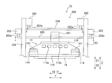
- the stage apparatus 1a includes a levitation assisting mechanism 200 for moving the movable table 11 from the outside of the movable range to the vicinity of the predetermined floating origin position within the movable range.
- the levitation assisting mechanism 200 includes a levitation origin assisting member 201, a pair of upper linear actuators 202, a pair of lower linear actuators 203, an upper bar 204, and a lower bar 205.
- the floating origin auxiliary member 201 is provided on the upper surface of the movable table 11.
- the floating origin auxiliary member 201 has an inverted U-shaped cross section (see FIG. 9) sandwiching the lower bar 205 when viewed from the Y direction, and both lower end portions (two lower end portions of the inverted U shape)
- the movable table 11 is installed so as to abut on the upper surface of the upper frame 116. Further, the floating origin auxiliary member 201 is installed in the vicinity of the center portion of the upper frame 116.
- the pair of upper linear actuators 202 are attached to the inner surface (the surface on the Y2 direction side) of the front surface portion 123 and the inner surface (the surface on the Y1 direction side) of the rear surface portion 124.
- the pair of upper linear actuators 202 are installed in the vicinity of the upper end portion of the front surface portion 123 and in the vicinity of the upper end portion of the rear surface portion 124 of the stage fixing portion 12.
- an output shaft 202a that can be driven in the Z direction is provided below the upper linear actuator 202.
- An upper bar 204 extending in the Y direction is attached to the lower ends of the two output shafts 202a.
- the upper bar 204 is disposed above the floating origin auxiliary member 201.
- the pair of lower linear actuators 203 are attached to the outer surface (the surface on the Y1 direction side) of the front surface portion 123 and the outer surface (the surface on the Y2 direction side) of the rear surface portion 124.
- the pair of lower linear actuators 203 are arranged on the lower side (Z2 direction side) than the upper linear actuator 202.
- an output shaft 203 a that can be driven in the Z direction is provided below the lower linear actuator 203.
- a lower bar 205 extending in the Y direction is attached to the lower ends of the two output shafts 203a.
- the lower bar 205 is provided so as to penetrate the inside of the inverted U-shaped portion of the floating origin auxiliary member 201.
- the movable table 11 is placed on the stopper stator 192 (see FIG. 4) when the stage apparatus 1a is started.
- the upper bar 204 and the lower bar 205 are separated from the floating origin auxiliary member 201 as shown in FIG.
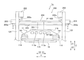
- the upper bar 204 is moved downward to bring the upper bar 204 into contact with the upper surface of the floating origin auxiliary member 201.
- the lower bar 205 is moved upward to bring the lower bar 205 into contact with the inner upper end surface of the inverted U-shaped portion of the floating origin auxiliary member 201.
- the output of the lower linear actuator 203 is made larger than that of the upper linear actuator 202, and the movable table 11 is lifted upward.
- the movable table 11 is moved to the vicinity of a predetermined floating origin position set in advance.
- the magnetic levitation unit 14 is driven, and the upper linear actuator 202 and the lower linear actuator 203 are driven to separate the upper bar 204 and the lower bar 205 from the levitation origin auxiliary member 201. Accordingly, the state shown in FIG. 7 is restored, and the movable table 11 located in the vicinity of the predetermined levitation origin position can be easily operated to the predetermined levitation origin position by the thrust of the magnetic levitation unit 14. Further, the upper bar 204 and the lower bar 205 separated from the floating origin auxiliary member 201 are moved to a position where they do not contact the floating origin auxiliary member 201 when the movable table 11 moves within the movable range.
- the magnetic levitation unit 14 is not used by providing the levitation assist mechanism 200 that levitates the movable table 11 in the vicinity of the levitation origin position set within the movable range of the movable table 11.
- the levitation assist mechanism 200 allows the movable table 11 to float from outside the movable range to within the movable range (near the floating origin position), so that the magnetic levitation unit 14 can be used only for driving within the movable range.
- the magnetic levitation unit 14 can be reduced in size.
- the upper linear actuator 202 moves the upper bar 204 downward (Z2 direction).
- the movable table 11 can be placed on the stopper stator 192 (see FIG. 4) by moving the upper surface of the floating origin auxiliary member 201 downward and pressing the upper surface. That is, the movable table 11 can be returned to the initial position not by manual operation but by the operation of the floating assist mechanism 200.
- the stage apparatus is applied to a magnetic levitation table apparatus used in an exposure apparatus, but the present invention is not limited to this.
- the stage apparatus may be applied to an apparatus used for purposes other than the exposure apparatus.
- the movable table is configured to hold the mask as the sample of the present invention
- the present invention is not limited to this.
- the movable table may be configured to hold a sample other than the mask.
- the present invention is not limited to this.
- the structure which provides only one linear motor may be sufficient, and the structure which provides several linear motors other than four may be sufficient.
- the linear motor movable element is constituted by a permanent magnet and the linear motor stator is constituted by a coil.
- the present invention is not limited to this.
- the linear motor stator may be constituted by a permanent magnet
- the linear motor movable element may be constituted by a coil.
- the present invention is not limited to this. In the present invention, only one floating unit movable element may be provided, or a plurality of floating unit movable elements other than four may be provided.
- the levitating unit mover is configured by a permanent magnet and the levitating unit stator is configured by a coil is shown, but the present invention is not limited to this.
- the levitating unit stator may be constituted by a permanent magnet
- the levitating unit mover may be constituted by a coil.
- the magnetic levitation unit capable of operating the movable table in both the X direction and the Z direction is shown as an example of the levitation unit of the present invention. Not limited to. In the present invention, a floating unit capable of moving the movable table only in the Z direction may be used.
- the present invention is not limited to this. In the present invention, it is only necessary that the linear motor is disposed inside the movable table as viewed in plan, and it is not necessary to arrange the linear motor inside the movable table.
- the present invention is not limited to this.
- the motor installation space may not be divided, and the motor installation space may be divided into a plurality of spaces other than four. In this case, a configuration in which a linear motor corresponding to the number of divisions is installed may be used.
- the rectangular motor installation space constituted by the lower frame 115, the upper frame 116, and the pair of side walls 113 as the frame-like portion of the present invention is divided into a horizontal partition portion and a vertical portion.
- this invention is not limited to this.
- two partition portions may be provided so as to connect diagonals of the rectangular motor installation space, and the motor installation space may be divided into four spaces.
- one linear motor movable element may be provided for one linear motor stator, or three or more linear motor movable elements may be provided for one linear motor stator. There may be.
- the stopper function unit 19 that limits the operation range in the X direction and the Z direction is shown as an example of the stopper unit.
- the present invention is not limited to this.
- a stopper portion that restricts the operation range in the X direction and a stopper portion that restricts the operation range in the Z direction may be provided separately.
- the upper frame and the lower frame both have a shorter length than the horizontal partition, but the present invention is not limited to this. In the present invention, it is only necessary that at least one of the upper frame and the lower frame has a shorter length than the horizontal partition.
Landscapes
- Physics & Mathematics (AREA)
- General Physics & Mathematics (AREA)
- Health & Medical Sciences (AREA)
- Engineering & Computer Science (AREA)
- Environmental & Geological Engineering (AREA)
- Epidemiology (AREA)
- Public Health (AREA)
- Container, Conveyance, Adherence, Positioning, Of Wafer (AREA)
- Exposure And Positioning Against Photoresist Photosensitive Materials (AREA)
- Exposure Of Semiconductors, Excluding Electron Or Ion Beam Exposure (AREA)
Abstract
Description
図1~図6を参照して、本発明の第1実施形態によるステージ装置1を備える磁気浮上テーブル装置100の構造について説明する。
次に、図7~図9を参照して、第2実施形態について説明する。この第2実施形態では、上記第1実施形態と異なり、ステージ装置1aの起動時において、図7に示す浮上補助機構200により、可動範囲外から可動範囲内の所定の浮上原点位置近傍まで可動テーブル11を移動させる構成について説明する。なお、この第2実施形態の可動テーブル11の構成は、上記第1実施形態と同じである。
Claims (20)
- 試料を保持するための可動テーブルと、
浮上ユニット可動子と浮上ユニット固定子とを含み、前記可動テーブルを少なくとも鉛直方向に動作させるための浮上ユニットと、
前記可動テーブルの内側に配置されたリニアモータ可動子と前記可動テーブルの内側に配置されたリニアモータ固定子とを含み、前記可動テーブルを水平面内の第1水平方向に動作させるためのリニアモータとを備える、ステージ装置。 - 前記可動テーブルの内部には、モータ設置空間が設けられており、
前記リニアモータ可動子と前記リニアモータ固定子とは、前記可動テーブルの内部の前記モータ設置空間に前記第1水平方向に延びるように配置されている、請求項1に記載のステージ装置。 - 前記リニアモータ可動子と前記リニアモータ固定子とを含む前記リニアモータは、前記可動テーブルの内部のモータ設置空間に、前記可動テーブルの重心を取り囲むように複数配置されている、請求項2に記載のステージ装置。
- 前記可動テーブルは、前記可動テーブルの重心を通り水平方向に延びる水平仕切り部と、前記可動テーブルの重心を通り鉛直方向に延びる鉛直仕切り部とを含み、
前記可動テーブルのモータ設置空間は、前記水平仕切り部および前記鉛直仕切り部により、4つの空間に分割されており、
前記4つの空間には、それぞれ、前記リニアモータ可動子および前記リニアモータ固定子を含む前記リニアモータが、前記可動テーブルの重心を取り囲むように配置されている、請求項3に記載のステージ装置。 - 前記4つの空間には、それぞれ、前記リニアモータ可動子および前記リニアモータ固定子を含む前記リニアモータが、前記可動テーブルの重心を取り囲むとともに、前記可動テーブルの重心を中心とする中心対称になるように配置されている、請求項4に記載のステージ装置。
- 前記リニアモータ可動子は、前記可動テーブルの前記水平仕切り部の上面に前記鉛直仕切り部を挟むように設置された第1リニアモータ可動子および第2リニアモータ可動子と、前記可動テーブルの水平仕切り部の下面に前記鉛直仕切り部を挟むように設置された第3リニアモータ可動子および第4リニアモータ可動子とを含み、
前記リニアモータ固定子は、前記第1リニアモータ可動子および前記第2リニアモータ可動子に対してそれぞれ鉛直方向に対向するように配置された第1リニアモータ固定子および第2リニアモータ固定子と、前記第3リニアモータ可動子および前記第4リニアモータ可動子に対してそれぞれ鉛直方向に対向するように配置された第3リニアモータ固定子および第4リニアモータ固定子とを含む、請求項4に記載のステージ装置。 - 前記可動テーブルは、前記水平仕切り部の外縁部および前記鉛直仕切り部の外縁部を取り囲むように設けられた枠状部をさらに含み、
前記枠状部により取り囲まれる空間が、前記モータ設置空間を構成するとともに、前記水平仕切り部および前記鉛直仕切り部により4つの格子状の空間に分割されており、
前記リニアモータ可動子は、前記枠状部の内部下表面に前記鉛直仕切り部を挟むように設置され、かつ、前記第1リニアモータ固定子および前記第2リニアモータ固定子に対してそれぞれ鉛直方向に対向するように配置された第5リニアモータ可動子および第6リニアモータ可動子と、前記枠状部の内部上表面に前記鉛直仕切り部を挟むように設置され、かつ、前記第3リニアモータ固定子および前記第4リニアモータ固定子に対してそれぞれ鉛直方向に対向するように配置された第7リニアモータ可動子および第8リニアモータ可動子とをさらに含み、
前記第1リニアモータ固定子、前記第1リニアモータ可動子および前記第5リニアモータ可動子により、第1リニアモータが構成され、前記第2リニアモータ固定子、前記第2リニアモータ可動子および前記第6リニアモータ可動子により、第2リニアモータが構成され、前記第3リニアモータ固定子、前記第3リニアモータ可動子および第7リニアモータ可動子により第3リニアモータが構成され、前記第4リニアモータ固定子、前記第4リニアモータ可動子および第8リニアモータ可動子により第4リニアモータが構成されている、請求項6に記載のステージ装置。 - 前記可動テーブルは、前記水平仕切り部の外縁部および前記鉛直仕切り部の外縁部を取り囲むように設けられた枠状部をさらに含み、
前記枠状部は、前記水平仕切り部に対して平行でかつ上側に位置する上側フレームと、前記水平仕切り部に対して平行でかつ下側に位置する下側フレームとを含み、
前記上側フレームおよび前記下側フレームのうち少なくともいずれかは、前記第1水平方向において、前記水平仕切り部よりも短い長さを有する、請求項4に記載のステージ装置。 - 前記リニアモータ固定子は、前記可動テーブルを貫通して前記可動テーブルの外側まで前記第1水平方向に延びるように配置され、
前記可動テーブルの外側において前記リニアモータ固定子を支持する固定子支持部材をさらに備える、請求項1に記載のステージ装置。 - 前記可動テーブルは、前記リニアモータを設置するためのモータ設置空間を構成する第1部分と前記浮上ユニットを配置するための第2部分とを有する可動部メインフレームを含み、
前記可動部メインフレームの前記第1部分と前記第2部分とは、一体的に形成されている、請求項1に記載のステージ装置。 - 前記可動部メインフレームの前記第1部分と前記第2部分とは、セラミック部材により一体的に形成されている、請求項10に記載のステージ装置。
- 前記浮上ユニットは、磁気浮上式であり、前記可動テーブルの外側に配置されている、請求項1に記載のステージ装置。
- 前記浮上ユニット可動子と前記浮上ユニット固定子とを含む前記浮上ユニットは、平面的に見て前記可動テーブルの重心を取り囲むように複数配置されている、請求項12に記載のステージ装置。
- 前記浮上ユニットは、前記可動テーブルの外側に突出するように設けられた突出部に取り付けられている、請求項12に記載のステージ装置。
- 前記突出部は、先端から根元に向かって徐々に鉛直方向の高さが大きくなるように形成されている、請求項14に記載のステージ装置。
- 前記浮上ユニットは、鉛直方向の駆動に加えて、前記第1水平方向と直交する水平面内の第2水平方向の駆動が可能なように構成されている、請求項1に記載のステージ装置。
- 前記可動テーブルの重心位置と、前記リニアモータの前記第1水平方向の推力の作用中心位置と、前記浮上ユニットの前記第2水平方向の推力の作用中心位置とが、鉛直方向において、同一の高さ位置である、請求項16に記載のステージ装置。
- 前記可動テーブルの重心位置を微調整するための調整ウェイトをさらに備え、
前記調整ウェイトは、前記可動テーブルの重心位置と、前記リニアモータの第1水平方向の推力の作用中心位置と、前記浮上ユニットの第2水平方向の推力の作用中心位置とが、鉛直方向において、同一の高さ位置になるように微調整可能なように構成されている、請求項17に記載のステージ装置。 - 前記ステージ装置の起動時に、前記可動テーブルの可動範囲内に設定された浮上原点位置近傍に前記可動テーブルを浮上させる浮上補助機構をさらに備える、請求項1に記載のステージ装置。
- 前記可動テーブルの動作範囲を制限するストッパ部をさらに備える、請求項1に記載のステージ装置。
Priority Applications (4)
| Application Number | Priority Date | Filing Date | Title |
|---|---|---|---|
| KR1020127021904A KR20130016198A (ko) | 2010-03-04 | 2010-12-20 | 스테이지 장치 |
| CN2010800651214A CN102782806A (zh) | 2010-03-04 | 2010-12-20 | 工作台装置 |
| JP2012502970A JP5370580B2 (ja) | 2010-03-04 | 2010-12-20 | ステージ装置 |
| US13/597,259 US8624445B2 (en) | 2010-03-04 | 2012-08-29 | Stage apparatus |
Applications Claiming Priority (2)
| Application Number | Priority Date | Filing Date | Title |
|---|---|---|---|
| JP2010047382 | 2010-03-04 | ||
| JP2010-047382 | 2010-03-04 |
Related Child Applications (1)
| Application Number | Title | Priority Date | Filing Date |
|---|---|---|---|
| US13/597,259 Continuation US8624445B2 (en) | 2010-03-04 | 2012-08-29 | Stage apparatus |
Publications (1)
| Publication Number | Publication Date |
|---|---|
| WO2011108170A1 true WO2011108170A1 (ja) | 2011-09-09 |
Family
ID=44541842
Family Applications (1)
| Application Number | Title | Priority Date | Filing Date |
|---|---|---|---|
| PCT/JP2010/072858 Ceased WO2011108170A1 (ja) | 2010-03-04 | 2010-12-20 | ステージ装置 |
Country Status (6)
| Country | Link |
|---|---|
| US (1) | US8624445B2 (ja) |
| JP (1) | JP5370580B2 (ja) |
| KR (1) | KR20130016198A (ja) |
| CN (1) | CN102782806A (ja) |
| TW (1) | TW201212097A (ja) |
| WO (1) | WO2011108170A1 (ja) |
Cited By (4)
| Publication number | Priority date | Publication date | Assignee | Title |
|---|---|---|---|---|
| JP2020111821A (ja) * | 2019-01-11 | 2020-07-27 | キヤノントッキ株式会社 | 成膜装置、電子デバイスの製造装置、成膜方法および電子デバイスの製造方法 |
| JP2021015285A (ja) * | 2017-03-31 | 2021-02-12 | 株式会社ニコン | 物体保持装置、処理装置、フラットパネルディスプレイの製造方法、及びデバイス製造方法 |
| WO2022264287A1 (ja) * | 2021-06-15 | 2022-12-22 | 株式会社日立ハイテク | ステージ装置、荷電粒子線装置および真空装置 |
| US12633494B2 (en) | 2021-06-15 | 2026-05-19 | Hitachi High-Tech Corporation | Stage device, charged particle beam device, and vacuum device |
Families Citing this family (3)
| Publication number | Priority date | Publication date | Assignee | Title |
|---|---|---|---|---|
| CN103909427B (zh) * | 2014-04-17 | 2016-05-04 | 电子科技大学 | 一种混合励磁磁悬浮进给平台 |
| CN106430088B (zh) * | 2016-08-30 | 2018-08-17 | 上海交通大学 | 一种六自由度磁浮磁驱纳米定位平台 |
| CN116418190A (zh) * | 2023-04-18 | 2023-07-11 | 上海世禹精密设备股份有限公司 | 高速移动避震方法及装置 |
Citations (4)
| Publication number | Priority date | Publication date | Assignee | Title |
|---|---|---|---|---|
| JP2000032733A (ja) * | 1998-07-09 | 2000-01-28 | Nikon Corp | 平面モータ装置及び露光装置 |
| WO2004105105A1 (ja) * | 2003-05-21 | 2004-12-02 | Nikon Corporation | ステージ装置及び露光装置、並びにデバイス製造方法 |
| JP2009016678A (ja) * | 2007-07-06 | 2009-01-22 | Yaskawa Electric Corp | ステージ装置およびその浮上制御方法と、ステージ装置を用いた露光装置 |
| WO2009128321A1 (ja) * | 2008-04-18 | 2009-10-22 | 株式会社安川電機 | 多自由度アクチュエータおよびステージ装置 |
Family Cites Families (15)
| Publication number | Priority date | Publication date | Assignee | Title |
|---|---|---|---|---|
| JP2714502B2 (ja) * | 1991-09-18 | 1998-02-16 | キヤノン株式会社 | 移動ステージ装置 |
| DE19601018A1 (de) * | 1995-01-27 | 1996-08-01 | Zeiss Carl Fa | Linear verstellbarer Präzisionstisch |
| JP3810039B2 (ja) * | 1998-05-06 | 2006-08-16 | キヤノン株式会社 | ステージ装置 |
| ATE390761T1 (de) | 1999-06-29 | 2008-04-15 | Cochlear Ltd | Schutzschaltung gegen hochspannung für standard cmos prozess |
| JP2001102279A (ja) | 1999-09-27 | 2001-04-13 | Nikon Corp | ステージ装置および露光装置 |
| TW546551B (en) * | 1999-12-21 | 2003-08-11 | Asml Netherlands Bv | Balanced positioning system for use in lithographic apparatus |
| US6271606B1 (en) * | 1999-12-23 | 2001-08-07 | Nikon Corporation | Driving motors attached to a stage that are magnetically coupled through a chamber |
| JP2001230305A (ja) * | 2000-02-18 | 2001-08-24 | Canon Inc | 支持装置 |
| JP4136363B2 (ja) * | 2001-11-29 | 2008-08-20 | キヤノン株式会社 | 位置決め装置及びそれを用いた露光装置 |
| US6873478B2 (en) * | 2002-06-21 | 2005-03-29 | Nikon Corporation | Kinematic lens mount with reduced clamping force |
| JP2004132435A (ja) * | 2002-10-09 | 2004-04-30 | Canon Inc | 軸受装置 |
| JP4672315B2 (ja) * | 2004-09-06 | 2011-04-20 | 東芝機械株式会社 | リニアモータおよびリニア移動ステージ装置 |
| JP4948886B2 (ja) | 2006-04-28 | 2012-06-06 | 株式会社安川電機 | ステージ装置および露光装置 |
| JP4853836B2 (ja) | 2007-09-19 | 2012-01-11 | 株式会社安川電機 | 精密微動位置決め装置およびそれを備えた微動位置決めステージ |
| JP2010014250A (ja) | 2008-07-07 | 2010-01-21 | Nikon Corp | 防振装置の製造方法、防振装置、ステージ装置及び露光装置 |
-
2010
- 2010-12-20 CN CN2010800651214A patent/CN102782806A/zh active Pending
- 2010-12-20 KR KR1020127021904A patent/KR20130016198A/ko not_active Ceased
- 2010-12-20 WO PCT/JP2010/072858 patent/WO2011108170A1/ja not_active Ceased
- 2010-12-20 JP JP2012502970A patent/JP5370580B2/ja not_active Expired - Fee Related
-
2011
- 2011-02-17 TW TW100105265A patent/TW201212097A/zh unknown
-
2012
- 2012-08-29 US US13/597,259 patent/US8624445B2/en not_active Expired - Fee Related
Patent Citations (4)
| Publication number | Priority date | Publication date | Assignee | Title |
|---|---|---|---|---|
| JP2000032733A (ja) * | 1998-07-09 | 2000-01-28 | Nikon Corp | 平面モータ装置及び露光装置 |
| WO2004105105A1 (ja) * | 2003-05-21 | 2004-12-02 | Nikon Corporation | ステージ装置及び露光装置、並びにデバイス製造方法 |
| JP2009016678A (ja) * | 2007-07-06 | 2009-01-22 | Yaskawa Electric Corp | ステージ装置およびその浮上制御方法と、ステージ装置を用いた露光装置 |
| WO2009128321A1 (ja) * | 2008-04-18 | 2009-10-22 | 株式会社安川電機 | 多自由度アクチュエータおよびステージ装置 |
Cited By (7)
| Publication number | Priority date | Publication date | Assignee | Title |
|---|---|---|---|---|
| JP2021015285A (ja) * | 2017-03-31 | 2021-02-12 | 株式会社ニコン | 物体保持装置、処理装置、フラットパネルディスプレイの製造方法、及びデバイス製造方法 |
| JP7192841B2 (ja) | 2017-03-31 | 2022-12-20 | 株式会社ニコン | 物体保持装置、処理装置、フラットパネルディスプレイの製造方法、及びデバイス製造方法 |
| JP2020111821A (ja) * | 2019-01-11 | 2020-07-27 | キヤノントッキ株式会社 | 成膜装置、電子デバイスの製造装置、成膜方法および電子デバイスの製造方法 |
| JP7499571B2 (ja) | 2019-01-11 | 2024-06-14 | キヤノントッキ株式会社 | 成膜装置、電子デバイスの製造装置、成膜方法および電子デバイスの製造方法 |
| WO2022264287A1 (ja) * | 2021-06-15 | 2022-12-22 | 株式会社日立ハイテク | ステージ装置、荷電粒子線装置および真空装置 |
| JP7620096B2 (ja) | 2021-06-15 | 2025-01-22 | 株式会社日立ハイテク | ステージ装置、荷電粒子線装置および真空装置 |
| US12633494B2 (en) | 2021-06-15 | 2026-05-19 | Hitachi High-Tech Corporation | Stage device, charged particle beam device, and vacuum device |
Also Published As
| Publication number | Publication date |
|---|---|
| US8624445B2 (en) | 2014-01-07 |
| CN102782806A (zh) | 2012-11-14 |
| JPWO2011108170A1 (ja) | 2013-06-20 |
| TW201212097A (en) | 2012-03-16 |
| KR20130016198A (ko) | 2013-02-14 |
| US20120319505A1 (en) | 2012-12-20 |
| JP5370580B2 (ja) | 2013-12-18 |
Similar Documents
| Publication | Publication Date | Title |
|---|---|---|
| JP5370580B2 (ja) | ステージ装置 | |
| US7057710B2 (en) | Stage system including fine-motion cable unit, exposure apparatus, and method of manufacturing device | |
| KR101584827B1 (ko) | 이동체 장치 및 노광 장치 | |
| JP4143438B2 (ja) | 支持装置、露光装置、デバイス製造方法 | |
| TWI630463B (zh) | 移動體裝置及曝光裝置、以及元件製造方法 | |
| US9435642B2 (en) | Position measuring apparatus, pattern transfer apparatus, and method for manufacturing a device | |
| WO2019225110A1 (ja) | ステージ装置、荷電粒子線装置および真空装置 | |
| KR20120091160A (ko) | 노광 장치, 노광 방법, 및 디바이스 제조 방법 | |
| EP4007136A1 (en) | Magnetic levitation stage device, and charged particle beam device or vacuum device in which magnetic levitation stage device is used | |
| JP2015230927A (ja) | 移動装置、荷電粒子線描画装置 | |
| JP2005142501A (ja) | ステージ装置および露光装置ならびにデバイス製造方法 | |
| JP6735693B2 (ja) | ステージ装置、及び荷電粒子線装置 | |
| JP5140103B2 (ja) | リニアモータ対、移動ステージ、及び電子顕微鏡 | |
| JP5943557B2 (ja) | 位置決め装置、露光装置およびデバイス製造方法 | |
| WO2004105105A1 (ja) | ステージ装置及び露光装置、並びにデバイス製造方法 | |
| JP2015230926A (ja) | 移動装置、荷電粒子線描画装置 | |
| JP2013051289A (ja) | 移動体装置、露光装置、フラットパネルディスプレイの製造方法、及びデバイス製造方法 | |
| JP2013036511A (ja) | 除振システム | |
| JP2011249555A (ja) | ステージ装置、露光装置及びデバイスの製造方法 | |
| JP2001230178A (ja) | 位置決め装置、露光装置およびデバイス製造方法 | |
| JP5090392B2 (ja) | ステージ装置 | |
| JP2001230177A (ja) | 位置決め装置、露光装置およびデバイス製造方法 | |
| JP2013214028A (ja) | 露光装置、フラットパネルディスプレイの製造方法、及びデバイス製造方法 | |
| JP6016433B2 (ja) | 位置決め装置、露光装置、デバイス製造方法 | |
| JP2016004922A (ja) | ステージ装置、リソグラフィ装置、及び物品の製造方法 |
Legal Events
| Date | Code | Title | Description |
|---|---|---|---|
| WWE | Wipo information: entry into national phase |
Ref document number: 201080065121.4 Country of ref document: CN |
|
| 121 | Ep: the epo has been informed by wipo that ep was designated in this application |
Ref document number: 10847066 Country of ref document: EP Kind code of ref document: A1 |
|
| WWE | Wipo information: entry into national phase |
Ref document number: 2012502970 Country of ref document: JP |
|
| ENP | Entry into the national phase |
Ref document number: 20127021904 Country of ref document: KR Kind code of ref document: A |
|
| NENP | Non-entry into the national phase |
Ref country code: DE |
|
| WWE | Wipo information: entry into national phase |
Ref document number: 8349/CHENP/2012 Country of ref document: IN |
|
| 122 | Ep: pct application non-entry in european phase |
Ref document number: 10847066 Country of ref document: EP Kind code of ref document: A1 |