WO2011108145A1 - カップラー - Google Patents
カップラー Download PDFInfo
- Publication number
- WO2011108145A1 WO2011108145A1 PCT/JP2010/069904 JP2010069904W WO2011108145A1 WO 2011108145 A1 WO2011108145 A1 WO 2011108145A1 JP 2010069904 W JP2010069904 W JP 2010069904W WO 2011108145 A1 WO2011108145 A1 WO 2011108145A1
- Authority
- WO
- WIPO (PCT)
- Prior art keywords
- retainer
- socket
- plug
- coupler
- retainers
- Prior art date
- Legal status (The legal status is an assumption and is not a legal conclusion. Google has not performed a legal analysis and makes no representation as to the accuracy of the status listed.)
- Ceased
Links
Images



Classifications
-
- F—MECHANICAL ENGINEERING; LIGHTING; HEATING; WEAPONS; BLASTING
- F16—ENGINEERING ELEMENTS AND UNITS; GENERAL MEASURES FOR PRODUCING AND MAINTAINING EFFECTIVE FUNCTIONING OF MACHINES OR INSTALLATIONS; THERMAL INSULATION IN GENERAL
- F16L—PIPES; JOINTS OR FITTINGS FOR PIPES; SUPPORTS FOR PIPES, CABLES OR PROTECTIVE TUBING; MEANS FOR THERMAL INSULATION IN GENERAL
- F16L37/00—Couplings of the quick-acting type
- F16L37/28—Couplings of the quick-acting type with fluid cut-off means
- F16L37/38—Couplings of the quick-acting type with fluid cut-off means with fluid cut-off means in only one of two pipe-end fittings
- F16L37/40—Couplings of the quick-acting type with fluid cut-off means with fluid cut-off means in only one of two pipe-end fittings with a lift valve being opened automatically when the coupling is applied
-
- F—MECHANICAL ENGINEERING; LIGHTING; HEATING; WEAPONS; BLASTING
- F16—ENGINEERING ELEMENTS AND UNITS; GENERAL MEASURES FOR PRODUCING AND MAINTAINING EFFECTIVE FUNCTIONING OF MACHINES OR INSTALLATIONS; THERMAL INSULATION IN GENERAL
- F16L—PIPES; JOINTS OR FITTINGS FOR PIPES; SUPPORTS FOR PIPES, CABLES OR PROTECTIVE TUBING; MEANS FOR THERMAL INSULATION IN GENERAL
- F16L37/00—Couplings of the quick-acting type
- F16L37/08—Couplings of the quick-acting type in which the connection between abutting or axially overlapping ends is maintained by locking members
- F16L37/084—Couplings of the quick-acting type in which the connection between abutting or axially overlapping ends is maintained by locking members combined with automatic locking
- F16L37/098—Couplings of the quick-acting type in which the connection between abutting or axially overlapping ends is maintained by locking members combined with automatic locking by means of flexible hooks
- F16L37/0985—Couplings of the quick-acting type in which the connection between abutting or axially overlapping ends is maintained by locking members combined with automatic locking by means of flexible hooks the flexible hook extending radially inwardly from an outer part and engaging a bead, recess or the like on an inner part
-
- H—ELECTRICITY
- H01—ELECTRIC ELEMENTS
- H01M—PROCESSES OR MEANS, e.g. BATTERIES, FOR THE DIRECT CONVERSION OF CHEMICAL ENERGY INTO ELECTRICAL ENERGY
- H01M8/00—Fuel cells; Manufacture thereof
- H01M8/04—Auxiliary arrangements, e.g. for control of pressure or for circulation of fluids
- H01M8/04082—Arrangements for control of reactant parameters, e.g. pressure or concentration
- H01M8/04186—Arrangements for control of reactant parameters, e.g. pressure or concentration of liquid-charged or electrolyte-charged reactants
-
- H—ELECTRICITY
- H01—ELECTRIC ELEMENTS
- H01M—PROCESSES OR MEANS, e.g. BATTERIES, FOR THE DIRECT CONVERSION OF CHEMICAL ENERGY INTO ELECTRICAL ENERGY
- H01M8/00—Fuel cells; Manufacture thereof
- H01M8/04—Auxiliary arrangements, e.g. for control of pressure or for circulation of fluids
- H01M8/04082—Arrangements for control of reactant parameters, e.g. pressure or concentration
- H01M8/04201—Reactant storage and supply, e.g. means for feeding, pipes
-
- H—ELECTRICITY
- H01—ELECTRIC ELEMENTS
- H01M—PROCESSES OR MEANS, e.g. BATTERIES, FOR THE DIRECT CONVERSION OF CHEMICAL ENERGY INTO ELECTRICAL ENERGY
- H01M8/00—Fuel cells; Manufacture thereof
- H01M8/04—Auxiliary arrangements, e.g. for control of pressure or for circulation of fluids
- H01M8/04082—Arrangements for control of reactant parameters, e.g. pressure or concentration
- H01M8/04201—Reactant storage and supply, e.g. means for feeding, pipes
- H01M8/04208—Cartridges, cryogenic media or cryogenic reservoirs
-
- H—ELECTRICITY
- H01—ELECTRIC ELEMENTS
- H01M—PROCESSES OR MEANS, e.g. BATTERIES, FOR THE DIRECT CONVERSION OF CHEMICAL ENERGY INTO ELECTRICAL ENERGY
- H01M8/00—Fuel cells; Manufacture thereof
- H01M8/10—Fuel cells with solid electrolytes
- H01M8/1009—Fuel cells with solid electrolytes with one of the reactants being liquid, solid or liquid-charged
- H01M8/1011—Direct alcohol fuel cells [DAFC], e.g. direct methanol fuel cells [DMFC]
-
- Y—GENERAL TAGGING OF NEW TECHNOLOGICAL DEVELOPMENTS; GENERAL TAGGING OF CROSS-SECTIONAL TECHNOLOGIES SPANNING OVER SEVERAL SECTIONS OF THE IPC; TECHNICAL SUBJECTS COVERED BY FORMER USPC CROSS-REFERENCE ART COLLECTIONS [XRACs] AND DIGESTS
- Y02—TECHNOLOGIES OR APPLICATIONS FOR MITIGATION OR ADAPTATION AGAINST CLIMATE CHANGE
- Y02E—REDUCTION OF GREENHOUSE GAS [GHG] EMISSIONS, RELATED TO ENERGY GENERATION, TRANSMISSION OR DISTRIBUTION
- Y02E60/00—Enabling technologies; Technologies with a potential or indirect contribution to GHG emissions mitigation
- Y02E60/30—Hydrogen technology
- Y02E60/50—Fuel cells
-
- Y—GENERAL TAGGING OF NEW TECHNOLOGICAL DEVELOPMENTS; GENERAL TAGGING OF CROSS-SECTIONAL TECHNOLOGIES SPANNING OVER SEVERAL SECTIONS OF THE IPC; TECHNICAL SUBJECTS COVERED BY FORMER USPC CROSS-REFERENCE ART COLLECTIONS [XRACs] AND DIGESTS
- Y10—TECHNICAL SUBJECTS COVERED BY FORMER USPC
- Y10T—TECHNICAL SUBJECTS COVERED BY FORMER US CLASSIFICATION
- Y10T137/00—Fluid handling
- Y10T137/8593—Systems
- Y10T137/87917—Flow path with serial valves and/or closures
- Y10T137/87925—Separable flow path section, valve or closure in each
- Y10T137/87941—Each valve and/or closure operated by coupling motion
- Y10T137/87949—Linear motion of flow path sections operates both
- Y10T137/87957—Valves actuate each other
-
- Y—GENERAL TAGGING OF NEW TECHNOLOGICAL DEVELOPMENTS; GENERAL TAGGING OF CROSS-SECTIONAL TECHNOLOGIES SPANNING OVER SEVERAL SECTIONS OF THE IPC; TECHNICAL SUBJECTS COVERED BY FORMER USPC CROSS-REFERENCE ART COLLECTIONS [XRACs] AND DIGESTS
- Y10—TECHNICAL SUBJECTS COVERED BY FORMER USPC
- Y10T—TECHNICAL SUBJECTS COVERED BY FORMER US CLASSIFICATION
- Y10T137/00—Fluid handling
- Y10T137/9029—With coupling
Definitions
- the present invention relates to a coupler constituted by a socket and a plug, which is detachably connected, so that a liquid can be easily transferred from a container to a container on the main body side, or the connected state can be reliably maintained when the container is replaced. Therefore, the present invention can be applied to a coupler in which the inner diameter of the connection hole on the socket side is further reduced, and is particularly suitable to be provided between the cartridge container of the methanol fuel cell and the fuel cell main body.
- a variety of detachable couplers are used in order to simplify the connection between the containers and the replacement of the containers, a socket having a valve body and a biasing means for biasing the valve body in a closing direction, and a valve body And a biasing means for biasing it in the closing direction, and a plug having a nozzle part that is detachably fitted and connected to the socket. Both valve bodies are opened so that they can communicate with each other, and both valve bodies are closed by being separated.
- Patent Document 1 As shown in FIG. 11, the plug P constituting the coupler is provided with the nozzle 1. While a pair of lock arms 2 projecting on both sides are provided, the socket S is provided with an engagement hole 3 with which the lock arm 2 is engaged, and a step between the protrusion 4 of the lock arm 2 and the engagement hole 3 is provided.
- the connected state can be maintained by engaging the part 5 with elastic deformation.
- a circumferential groove 7 is formed at the tip of the nozzle 6 of the plug P of the fuel cell coupler, and the socket S is a hole into which the nozzle 6 is inserted.
- the four hooks 9 are arranged so as to protrude from the outer side to the inner peripheral side and urged so as to protrude forward by an elastic body so as to get over the hook 9, and then the hook 9 is inserted into the circumferential groove 7.
- the connected state can be maintained by being engaged.
- the present invention has been made in view of the above-described problems of the prior art, and is intended to provide a coupler that is easy to connect and can protect the tip of the nozzle from unforeseen circumstances such as dropping while being ultra-compact. Is.
- a coupler according to claim 1 of the present invention includes a socket including a valve body and an urging means for urging the valve body in a closing direction, a valve body and the urging means in the closing direction.
- a coupler that includes a nozzle portion that is detachably fitted and connected to the socket, and includes a plug that can be communicated by opening both valve bodies in a fitted and connected state.
- a connecting and holding means constituted by a retainer for holding the connected state and a retainer locking portion, and a pair of the retainers are provided opposite to each other with the nozzle portion of the plug interposed therebetween.
- a locking claw portion that is locked to the retainer locking portion is formed on the inside of the front end portion of the opposing portion, and the locking claw portions of the pair of retainers are equal to the outer diameter of the nozzle portion or While being provided at a narrow interval, the pair of retainers is formed higher than the tip of the nozzle portion.
- the retainer claw portion of the retainer is formed with an interference preventing portion for preventing interference with the nozzle portion. It is what.
- the retainer in addition to the configuration according to the first or second aspect, is formed with a thin wall portion serving as a fulcrum of elastic deformation at the intermediate portion, and the locking claw portion is thick. It is characterized in that it is formed.
- the retainer is configured to be rotatable about the nozzle portion as a central axis.
- the coupler according to claim 5 of the present invention is characterized in that, in addition to the configuration according to claim 4, the retainer is provided with a ride-over portion that can regulate a rotational position between the retainer and the nozzle portion. is there.
- the plug in addition to the structure according to any one of the first to fifth aspects, includes a cam mechanism for releasing the connection when a twisting force is applied to the plug while the retainer is connected. It is characterized by having.
- the cam mechanism comprises a cam provided on the plug and a cam follower of a release ring provided on the retainer so as to be able to reciprocate. It is characterized by.
- the width of the retainer is 2.8 to 4.0 mm and the distance between the outer sides of the pair of retainers is The distance is 6.0 to 10.0 mm.
- the socket of the coupler has the socket mounted at a substantially central portion of an insertion port for receiving the pair of retainers.
- the socket including the valve body and the biasing means for biasing the valve body in the closing direction, and the biasing means for biasing the valve body in the closing direction are provided.
- a coupler comprising a nozzle portion that is detachably fitted and connected to the socket, and a plug that can be communicated by opening both valve bodies in a fitted and connected state, Between the socket and the plug, there is provided a connecting and holding means constituted by a retainer for holding the connected state and a retainer locking portion, and a pair of the retainers are provided opposite to each other with the nozzle portion of the plug interposed therebetween.
- a locking claw portion that is locked to the retainer locking portion is formed on the inside of the front end portion of the opposing portion, and the locking claw portions of the pair of retainers are equal to the outer diameter of the nozzle portion or
- these one pair of retainers are formed higher than the tip of the nozzle part while being provided at a narrow interval, so by forming a locking claw part inside the pair of retainers that sandwich the nozzle part, In the initial state, the gap with the nozzle part can be reduced and the periphery of the nozzle part can be protected.
- the height of the retainer can be made higher than the tip of the nozzle portion, so that the nozzle portion can be protected by the retainer even in an unexpected situation such as dropping, so that the nozzle portion can be prevented from being directly damaged.
- the interference claw portion of the retainer is formed with the interference prevention portion for preventing the interference with the nozzle portion
- the interference prevention portion is formed in the engagement claw portion. And can be installed at an interval narrower than the outer diameter of the nozzle portion, and further miniaturization can be achieved.
- the retainer is formed with a thin wall portion serving as a fulcrum of elastic deformation in the intermediate portion, and the locking claw portion is formed with a thick wall.
- the wall By making the wall thick, it is possible to ensure the strength necessary for maintaining the connected state and to increase the drop strength.
- the retainer is configured to be rotatable about the nozzle portion as a central axis, so that damage to the retainer and the socket can be prevented even if a twisting force is applied in a connected state. it can.
- the retainer includes the overriding portion that can restrict the rotational position between the nozzle portion and the rotational position of the retainer even if it is a rotatable retainer. By doing so, the position of the retainer can be confirmed and the coupling operation can be easily performed.
- the plug since the plug is provided with a cam mechanism that releases the connection when a twisting force is applied in the connected holding state of the retainer, the plug is twisted in the connected holding state by the cam mechanism. Even when force is applied, the connected state can be released, and damage to the coupler can be prevented.
- the cam mechanism is composed of the cam provided on the plug and the cam follower of the release ring provided on the retainer so as to be able to reciprocate.
- the width of the retainer is 2.8 to 4.0 mm, and the distance between the outer sides of the pair of retainers is 6.0 to 10.0 mm. Therefore, it is possible to reduce the size of the coupler, and it is possible to provide a coupler that can be mounted on a device having a thin device body such as a mobile phone or a portable audio device. Since the tip is rectangular, it is easy to grasp the orientation at the time of connection.
- the socket of the coupler is mounted at a substantially central portion of an insertion port for receiving the pair of retainers, and the retainer locking portion is provided outside the socket. Accordingly, since the concave portion integrated with the insertion port is configured, the socket side can be made compact by making the insertion port on the socket side and the retainer locking portion an integral concave portion.
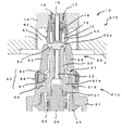
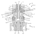
- the coupler 10 includes a socket S10 and a plug P10 fitted and connected to the socket S10.
- the socket S10 is provided on the main body side of the methanol fuel cell
- the plug P10 is provided on the cartridge side as a methanol container.
- the main part is made up of metallic materials and non-metallic materials such as polypropylene, polyphenylene sulfide, polyacetal and other synthetic resins. Made.
- a substantially cylindrical socket that constitutes the coupler main body via a socket holding frame member 11 provided with a space recess serving as an insertion port in a member F that is integrally or separately attached to the main body of the fuel cell.
- a main body 12 is mounted, and a plug connection hole 13 that forms an insertion port of a plug into which a plug P10 that is paired with the socket S10 is inserted and connected is formed at the tip (lower side in the figure).
- a valve holder 14 having a substantially bottomed cylindrical hole is shown on the base end side (upper side in the drawing) of the socket body 12, and a portion of the socket body 12 is omitted in the figure.
- a communication hole for communication is formed.
- a socket-side operation member 15 composed of a connection channel and a pipe for opening and closing the valve is disposed at the center of the socket body 12, and the cylindrical portion and the cross-section J between the socket-side operation member 15 and the socket body 12 are arranged.
- a seal member 16 integrally formed with a letter-shaped diaphragm portion is mounted, and a valve body 18 urged by a compression coil spring 17 in the valve holder 14 with the top of the diaphragm portion of the seal member 16 as a valve seal portion is provided. It is slidably stored.
- valve body 18 is pushed against the compression coil spring 17 through the socket-side operation member 15 due to the connection with the plug P10, and a gap is formed between the valve body 18 and the seal member 16, thereby forming the valve body 18.
- the plug body 31 includes a substantially four-stage cylindrical plug body 31 that constitutes a coupler body to be screwed into the container.
- the plug body 31 protrudes from the distal end portion and is mounted in the plug connection hole 13 of the socket S10.
- a projecting connecting portion 32 that forms a small-diameter, generally cylindrical nozzle portion is formed, a seal recess 32a is formed at the tip of the projecting connecting portion 32, and a plug-side operation member 33 composed of a pipe at the center. Is attached.
- the coupling state of the coupler 10 is brought into contact with the outer peripheral surface of the front end portion of the seal member 16 of the socket side operation member 15 of the socket S10 and the inner peripheral surface of the seal concave portion 32a.
- a valve holder 34 (not shown) is connected to the proximal end portion (downward in the drawing) of the plug-side operation member 33 of the plug body 31, and a communication groove communicating with the inside of the container is formed at the bottom portion.
- a valve body 36 urged by a compression coil spring 35 is slidably accommodated in the valve holder 34.
- a valve seal member 37 formed of an O-ring is attached to the upper outer periphery of the valve main body 36 so that the gap between the plug main body 31 and the stepped portion can be opened and closed.
- valve body 36 is pushed against the compression coil spring 35 via the plug-side operation member 33 due to the connection with the socket S 10, and between the valve body 36 and the step portion of the valve seal member 37 or the plug body 31.
- the valve body 36 is automatically opened when a gap is formed in the valve, the valve is interposed between the center portion of the pipe of the plug-side operation member 33 and between the valve body 36 and the valve seal member 37 or the step portion of the plug body 31.
- the inside of the container communicates with the communication groove at the bottom of the holder 34.
- a connection holding means 50 is provided to hold the connection state between the socket S10 and the plug P10.
- a retainer locking portion 52 provided on one side of the connection holding means 50 in the engagement recess 51, etc.
- the other side engaged with the retainer locking portion 52 of the engaging recess 51 is provided on the plug P10 as the retainer 53 and its locking claw portion 54, and so on. It is designed to be engaged and held by one action of pushing and to be released by one action of pulling out and to supply fuel or the like in a stable connected state.
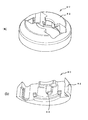
- the space concave portion of the socket holding frame member 11 attached to the member F on the main body side of the fuel cell is used as the engagement concave portion 51, and the socket main body 12 is arranged in the engagement concave portion 51.
- a pair of retainer locking portions 52 on one side of the connection holding means 50 are provided on the outer side of the distal end portion with the socket body 12 interposed therebetween, and as shown in FIG.
- the mounting hole is an integral recess as an insertion port.
- a pair of retainer locking portions 52 are formed in a hook shape on the outer surface of the socket body 12 located at the center of the engaging recess 51 so as to protrude outward from the central axis side.
- the side of the retainer 53 on the side of the plug P10 which will be described later, forms a recess that receives the retainer 53 by the retainer locking portion 52 and the engagement recess 51, and has a stepped surface that is inclined at the side and has a base end at a right angle. After the latching claw portion 54 gets over smoothly, the engagement is surely made.
- the socket S10 is attached to the substantially central portion of the insertion port for receiving the pair of retainers 53, and the protruding connecting portion 32 that is the nozzle portion of the plug P10 can be connected.
- the retainer locking portions 52, 52 By providing the retainer locking portions 52, 52, a recess is formed integrally with the insertion port that receives the pair of retainers 53, 53.
- the thickness is orthogonal to the thickness of the body F of a device such as a fuel cell.
- An engagement recess 51 that is long in the horizontal direction is disposed, so that the installation space can be made as small as possible, and the connection holding means 50 can be easily installed even in a thin apparatus.
- the engaging recess 51 and the socket body 12 are formed as an integral recess, it can be used as a guide when connecting the socket S10 and the plug P10.
- connection holding means 50 that holds the connection state with the socket S10 at the tip of the plug body 31.
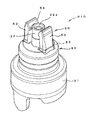
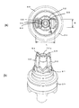
- a retainer 53 serving as two lock arms corresponding to the engaging recess 51 and the retainer locking portion 52 of the socket S10 protrudes upward and faces the projecting connecting portion 32 as a nozzle portion.
- a pair of members is provided, and is provided as a member separate from the plug body 31 so as to be rotatable around the central axis of the plug P10.
- the retainer 53 serving as these two lock arms is formed with a locking claw portion 54 so as to protrude inside the distal end portion, and a substantially disc-shaped ring portion 55 at the base end portion.
- the hollow portion is fitted into the intermediate small-diameter portion 31a of the plug main body 31, and is rotatable about the central axis so as to cover the intermediate large-diameter portion 31b.
- Two retainers 53 are provided on the disk of the ring portion 55. Is formed so that it is almost vertical and tilts inward.
- locking part 52 of the engaging recessed part 51 protrudes and forms in the front-end
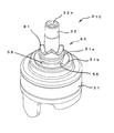
- a plurality of radial recesses are formed at equal intervals around the circumference, and the corresponding protruding portions 56 of the protrusions are formed on the horizontal surface of the plug body 31,
- the rotational position of the retainer 53 can be regulated by the concave portion and the overpass portion 56.
- the pair of retainers 53 provided between the projecting connecting portions 32 constituting the nozzle portion is formed higher than the projecting connecting portions 32, and even if the plug P10 is dropped, the projecting connecting portions 32 are used. It is designed to prevent accidental damage to a nozzle part.
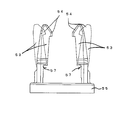
- a thin wall portion 57 is provided in which the intermediate portion of the retainer 53 is formed thin, while the front and rear ends sandwiching the intermediate portion.
- the portion is formed to be thick, so that the necessary displacement is ensured at the same time as the fulcrum of elastic deformation at the time of connection is an intermediate thin portion 57, and at the same time, the strength necessary for connection holding can be ensured.
- an interference preventing portion 58 for preventing interference with the projecting coupling portion 32 that is a nozzle portion is formed in the engagement claw portion 54 on the inner side of the distal end portion of the retainer 53 in a circular arc shape.
- the gap between the claw portions 54 is narrower than the outer diameter of the protruding connecting portion 32 that is the nozzle portion, and is arranged as close to the protruding connecting portion 32 as possible, and the retainer 53 is elastically deformed outward, thereby making it approach in the initial state. This makes it possible to achieve compactness and miniaturization.
- the protruding base portion of the engaging claw portion 54 is configured in a straight line in response to the hook shape of the retainer locking portion 52 so that the stress at the time of coupling engagement is evenly distributed.
- the width B of the retainer 53 of the connection holding means 50 is preferably equal to or larger than the outer diameter of the nozzle portion.
- the outer width of the protruding connection portion 32 that is the nozzle portion of the plug P10 is used.
- the distance L is set to about 2.8 to 4.0 mm and the distance L between the outsides of the pair of retainers 53 can be reduced to about 6.0 to 10.0 mm. It can be used with a coupler for small devices such as mobile phones and portable audio devices.
- the protruding connecting portion 32 that is the nozzle portion of the plug P10 is inserted into the plug connection hole 13 that is the insertion port of the plug of the socket S10.
- a retainer 53 serving as a lock arm provided in the plug main body 31 is pushed in so as to face the engaging recess 51 and the retainer engaging portion 52 as an insertion port of the connection holding means 50 provided in the socket main body 12.
- the retainer 53 is pushed back outward by the contact between the retainer locking portion 52 of the engagement recess 51 and the engagement claw portion 54 of the retainer 53.
- the intermediate thin portion 57 is elastically deformed with the fulcrum as a fulcrum, and the plug P10 is further pushed in, so that the retainer locking portion 52 of the engaging recess 51 and the engaging claw portion 54 of the retainer 53 are engaged with each other.
- the connected state is maintained between the stepped surfaces.
- the retainer 53 is rotatable with respect to the plug main body 31 through the ring portion 55 around the central axis, so that a force around the central axis is applied between the socket S10 and the plug P10. Also, the retainer 53 can be allowed to rotate, and damage to the coupler 10 can be prevented.
- connection holding state when the connection holding state is released, when the plug P10 is pulled out from the socket S10, the slight inclined surface of the engaging claw portion 54 of the retainer 53 is retained by the retainer locking portion 52 of the engaging recess 51. 53 can be elastically deformed so as to push back outward, and can be pulled out to get over each other to release and release the connected holding state.
- this coupler 10 when a twisting force is applied in a state where the connection and holding mechanism 50 is connected and held, the ring portion 55 of the retainer 53 is not only released so as to be rotatable with respect to the plug body 31 but also automatically connected and held.
- a cam mechanism 80 is provided so that the state can be released.
- the cam mechanism 80 includes four cams 81 at regular intervals (every 90 degrees) on the outer periphery of the base end portion of the projecting coupling portion 32 that is the nozzle portion of the plug body 31 of the plug P10. It is formed by an end face cam in which both ends in the circumferential direction are inclined surfaces and a center part is formed in a curved surface.
- the end face cam 81 is engaged from the state in which the engagement claw portion 54 of the retainer 53 of the plug P10 is engaged and connected to the retainer locking portion 52 of the engagement recess 51 of the socket S10 by the connection holding means 50. It is a cam with a height that can secure a lift amount that can be opened.
- a release ring 82 is slidably covered so as to cover the outside of the retainer 53 of the plug main body 31 of the plug P10 from above, and as shown in FIG. Protruding cam followers 83 are formed at two diagonal positions.
- the top surface of the release ring 82 faces the outer surface of the fuel cell main body F in the connection protection state.
- the central axis between the plug P10 and the socket S10 in a state where the retainer engaging portion 52 of the engaging recess 51 of the socket S10 and the engaging claw portion 54 of the retainer 53 of the plug P10 are engaged and held.
- the ring portion 55 of the retainer 53 is rotatable with respect to the plug main body 31 with a slight rotational force. This can be allowed within the range of play of the cam mechanism 80.
- the cam 81 of the cam mechanism 80 is rotated by the relative rotation of the socket S10 and the plug P10.
- the release ring 82 is guided by the retainer 53 via the cam follower 83 of the release ring 82 that is in contact with the cam 81 and lifted in the axial direction, and the top surface of the release ring 82 hits the outer surface of the fuel cell main body F.
- the retainer locking portion 52 of the engaging recess 51 of the socket S10 and the engaging claw portion 54 of the retainer 53 of the plug P10 are connected and held. The combined state is released.
- the cam mechanism 80 prevents damage caused by the rotation of the ring portion 55 of the retainer 53 when a twisting force in the rotational direction is applied, and generates an axial force to automatically release the connected holding state. can do.
- this cam mechanism 80 even when the plug P10 is removed from the socket S10, it can be removed by generating a pulling force easily by twisting it so as to apply a rotational force around the central axis.
- the shapes of the retainer 53A of the connection holding means 50 of the plug P10A and the release ring 82A of the cam mechanism 80 are changed, and the engaging claw portion 54A of the retainer 53A is the retainer locking portion of the engaging recess 51.
- the rear surface of the retainer 53A comes into contact with the inner side of the release ring 82A (X portion in the drawing) and resists deformation.
- the shape inside is set.
Landscapes
- Engineering & Computer Science (AREA)
- General Engineering & Computer Science (AREA)
- Sustainable Energy (AREA)
- Life Sciences & Earth Sciences (AREA)
- Manufacturing & Machinery (AREA)
- Sustainable Development (AREA)
- Chemical & Material Sciences (AREA)
- Chemical Kinetics & Catalysis (AREA)
- Electrochemistry (AREA)
- General Chemical & Material Sciences (AREA)
- Mechanical Engineering (AREA)
- Quick-Acting Or Multi-Walled Pipe Joints (AREA)
- Joints With Pressure Members (AREA)
- Closures For Containers (AREA)
Abstract
Description
これらソケットとプラグとの間に、連結状態を保持するリテーナとリテーナ係止部とで構成される連結保持手段を設け、このリテーナを前記プラグのノズル部を挟んで対向して一対設け、このリテーナの対向部の先端部内側に前記リテーナ係止部に係止される係止爪部を突出させて形成するとともに、これら1対のリテーナの係止爪部を前記ノズル部の外径と同等あるいは狭い間隔で設ける一方、これら1対のリテーナを前記ノズル部先端より高く形成してなることを特徴とするものである。
これらソケットとプラグとの間に、連結状態を保持するリテーナとリテーナ係止部とで構成される連結保持手段を設け、このリテーナを前記プラグのノズル部を挟んで対向して一対設け、このリテーナの対向部の先端部内側に前記リテーナ係止部に係止される係止爪部を突出させて形成するとともに、これら1対のリテーナの係止爪部を前記ノズル部の外径と同等あるいは狭い間隔で設ける一方、これら1対のリテーナを前記ノズル部先端より高く形成したので、ノズル部を挟む1対のリテーナの内側に係止爪部を形成することで、係止の際には外側に移動させて初期状態では、ノズル部との隙間を小さくすることができるとともに、ノズル部の周囲を保護することができる。また、リテーナの高さをノズル部先端より高くして落下などの不測の事態でもリテーナでノズル部を保護することができ、直接ノズル部に損傷が及ばないようにすることができる。
このカップラー10は、ソケットS10と、このソケットS10と嵌合連結されるプラグP10とで構成され、例えばメタノール燃料電池の本体側にソケットS10が設けられ、メタノール容器としてのカートリッジ側にプラグP10が設けられ、互いを連通させて本体側に燃料を補充したり、カートリッジごと交換するのに用いられ、主要部は、金属材料と、非金属材料、例えばポリプロピレン、ポリフェニレンサルファイド、ポリアセタールなどの合成樹脂とで作られる。
S10 ソケット
P10 プラグ
F メタノール燃料電池の本体側の部材
11 ソケット保持枠部材(挿入口)
12 ソケット本体
13 プラグ接続孔(挿入口)
14 弁ホルダ
15 ソケット側操作部材
16 シール部材
17 圧縮コイルばね
18 バルブ本体
31 プラグ本体
31a 中間小径部
31b 中間大径部
32 突出連結部(ノズル部)
32a シール凹部
33 プラグ側操作部材
34 バルブホルダ
35 圧縮コイルばね
36 バルブ本体
37 弁シール部材
50 連結保持手段
51 係合凹部
52 リテーナ係止部
53 リテーナ
55 リング部
56 乗り越え部
57 薄肉部
58 干渉防止部
80 カム機構
81 カム
82 解除リング
83 カムフォロア
10A カップラー
51A 係合凹部
53A リテーナ
82A 解除リング
54A 係合爪部
X 当接部
Claims (9)
- 弁体とこれを閉方向に付勢する付勢手段とを備えるソケットと、弁体とこれを閉方向に付勢する付勢手段とを備えるとともに、前記ソケットと着脱可能に嵌合連結されるノズル部を備え嵌合連結状態で両弁体を開放して連通可能なプラグとから構成されるカップラーであって、
これらソケットとプラグとの間に、連結状態を保持するリテーナとリテーナ係止部とで構成される連結保持手段を設け、このリテーナを前記プラグのノズル部を挟んで対向して一対設け、このリテーナの対向部の先端部内側に前記リテーナ係止部に係止される係止爪部を突出させて形成するとともに、これら1対のリテーナの係止爪部を前記ノズル部の外径と同等あるいは狭い間隔で設ける一方、これら1対のリテーナを前記ノズル部先端より高く形成してなることを特徴とするカップラー。 - 前記リテーナの係止爪部には、前記ノズル部との干渉を防止する干渉防止部を形成してなることを特徴とする請求項1記載のカップラー。
- 前記リテーナには、中間部に弾性変形の支点となる薄肉部を形成するとともに、係止爪部を厚肉に形成したことを特徴とする請求項1または2記載のカップラー。
- 前記リテーナは、前記ノズル部を中心軸に回転可能に構成したことを特徴とする請求項1~3のいずれかに記載のカップラー。
- 前記リテーナは、前記ノズル部との間に回転位置を規制し得る乗り越え部を備えていることを特徴とする請求項4記載のカップラー。
- 前記プラグには、前記リテーナの連結保持状態でひねり力が加わると連結を解除するカム機構を備えていることを特徴とする請求項1~5のいずれかに記載のカップラー。
- 前記カム機構を、プラグに設けたカムと、前記リテーナに往復動可能に設けた解除リングのカムフォロアとで構成したことを特徴とする請求項6記載のカップラー。
- 前記リテーナの幅を、2.8~4.0mmとするとともに、1対のリテーナの外側間の距離を6.0~10.0mmとして構成したことを特徴とする請求項1~7のいずれかに記載のカップラー。
- 前記カップラーのソケットでは、前記一対のリテーナを受け入れる挿入口の略中央部に前記ソケットを装着し、前記ソケットの外側に前記リテーナ係止部を設けることにより、前記挿入口と一体の凹部を構成してなることを特徴とする請求項1~8のいずれかに記載のカップラー。
Priority Applications (2)
| Application Number | Priority Date | Filing Date | Title |
|---|---|---|---|
| US13/581,842 US8851115B2 (en) | 2010-03-03 | 2010-11-09 | Coupler |
| CN201080066583.8A CN102918315B (zh) | 2010-03-03 | 2010-11-09 | 联接器 |
Applications Claiming Priority (2)
| Application Number | Priority Date | Filing Date | Title |
|---|---|---|---|
| JP2010046207A JP5736649B2 (ja) | 2010-03-03 | 2010-03-03 | カップラー |
| JP2010-046207 | 2010-03-03 |
Publications (1)
| Publication Number | Publication Date |
|---|---|
| WO2011108145A1 true WO2011108145A1 (ja) | 2011-09-09 |
Family
ID=44541821
Family Applications (1)
| Application Number | Title | Priority Date | Filing Date |
|---|---|---|---|
| PCT/JP2010/069904 Ceased WO2011108145A1 (ja) | 2010-03-03 | 2010-11-09 | カップラー |
Country Status (4)
| Country | Link |
|---|---|
| US (1) | US8851115B2 (ja) |
| JP (1) | JP5736649B2 (ja) |
| CN (1) | CN102918315B (ja) |
| WO (1) | WO2011108145A1 (ja) |
Cited By (1)
| Publication number | Priority date | Publication date | Assignee | Title |
|---|---|---|---|---|
| CN114542834A (zh) * | 2020-11-24 | 2022-05-27 | 株式会社龙野 | 管接头 |
Families Citing this family (13)
| Publication number | Priority date | Publication date | Assignee | Title |
|---|---|---|---|---|
| US9812684B2 (en) | 2010-11-09 | 2017-11-07 | GM Global Technology Operations LLC | Using elastic averaging for alignment of battery stack, fuel cell stack, or other vehicle assembly |
| US9534735B2 (en) * | 2011-11-23 | 2017-01-03 | Husky Corporation | Pressure-locking nozzle for dispensing gaseous fluid |
| US20140210203A1 (en) * | 2013-01-31 | 2014-07-31 | Eaton Corporation | Fluid Couplling Assembly with Integral Plug Retainer |
| DE112014000730T5 (de) | 2013-02-08 | 2015-10-15 | Norma U.S. Holding Llc | Kraftstoffleitung-Verbindungsanordung |
| FR3004780B1 (fr) | 2013-04-17 | 2015-05-01 | Raymond A & Cie | Verrou pour raccordement tubulaire et raccord tubulaire obtenu |
| US9457845B2 (en) | 2013-10-02 | 2016-10-04 | GM Global Technology Operations LLC | Lobular elastic tube alignment and retention system for providing precise alignment of components |
| US9511802B2 (en) | 2013-10-03 | 2016-12-06 | GM Global Technology Operations LLC | Elastically averaged alignment systems and methods |
| US9669774B2 (en) | 2013-10-11 | 2017-06-06 | GM Global Technology Operations LLC | Reconfigurable vehicle interior assembly |
| US9435472B2 (en) * | 2013-10-17 | 2016-09-06 | Mahle International Gmbh | Coupler including clamp for connection to a corrugated tube |
| US9541113B2 (en) | 2014-01-09 | 2017-01-10 | GM Global Technology Operations LLC | Elastically averaged alignment systems and methods |
| US9657807B2 (en) | 2014-04-23 | 2017-05-23 | GM Global Technology Operations LLC | System for elastically averaging assembly of components |
| US9758110B2 (en) | 2015-01-12 | 2017-09-12 | GM Global Technology Operations LLC | Coupling system |
| CN111810744B (zh) * | 2020-07-03 | 2022-05-10 | 瑞肯耐特流体控制系统(镇江)有限公司 | 快速连接器 |
Citations (3)
| Publication number | Priority date | Publication date | Assignee | Title |
|---|---|---|---|---|
| JP2007085471A (ja) * | 2005-09-22 | 2007-04-05 | Toyo Seikan Kaisha Ltd | カップラー |
| JP2007132473A (ja) * | 2005-11-11 | 2007-05-31 | Nitto Kohki Co Ltd | 管継手 |
| JP2007218387A (ja) * | 2006-02-20 | 2007-08-30 | Toyo Seikan Kaisha Ltd | カップラー |
Family Cites Families (18)
| Publication number | Priority date | Publication date | Assignee | Title |
|---|---|---|---|---|
| US2444451A (en) * | 1945-10-18 | 1948-07-06 | Utilities Distributors Inc | Fluid coupling |
| US2819914A (en) * | 1955-03-17 | 1958-01-14 | George R Eitner | Fluid line coupling device |
| US4458719A (en) * | 1981-11-02 | 1984-07-10 | Imperial Clevite Inc. | Quick coupler service fitting |
| IT8534836V0 (it) * | 1985-04-02 | 1985-04-02 | Gf Srl | Raccordo ad innesto rapido per tubi flessibili in genere |
| US5564471A (en) * | 1995-01-23 | 1996-10-15 | Dover Corporation | Fuel hose breakaway unit |
| US5897142A (en) * | 1996-12-19 | 1999-04-27 | Itt Automotive, Inc. | Push-to-release quick connector |
| EP0896182B1 (fr) * | 1997-07-17 | 2002-04-10 | Interlemo Holding S.A. | Système connecteur |
| US6343630B1 (en) * | 1998-05-22 | 2002-02-05 | Delaware Capital Formation, Inc. | High pressure filling nozzle |
| US20040074541A1 (en) * | 2002-07-04 | 2004-04-22 | Andrew Sharpe | Flow connector |
| US6834888B2 (en) * | 2003-02-04 | 2004-12-28 | Flow-Rite Controls, Ltd. | Connector |
| KR20090082283A (ko) | 2004-12-24 | 2009-07-29 | 도요 세이칸 가부시키가이샤 | 커플러 |
| JP2006177492A (ja) | 2004-12-24 | 2006-07-06 | Toyo Seikan Kaisha Ltd | カップラー |
| JP2007132472A (ja) | 2005-11-11 | 2007-05-31 | Toyota Motor Corp | ディスクロータ状態検出装置 |
| US7431346B2 (en) | 2005-11-21 | 2008-10-07 | Campbell Hausfeld/Scott Fetzer Company | Quick connect coupling |
| JP2007192287A (ja) | 2006-01-19 | 2007-08-02 | Toyo Seikan Kaisha Ltd | カップラー |
| WO2007083834A1 (ja) | 2006-01-19 | 2007-07-26 | Toyo Seikan Kaisha, Ltd. | カップラーおよび燃料電池用の燃料カートリッジ |
| JP2007311292A (ja) | 2006-05-22 | 2007-11-29 | Toshiba Corp | 燃料電池用カップラとそれを用いた燃料電池 |
| US7490865B1 (en) * | 2007-07-30 | 2009-02-17 | Tzu Liang Tsai | Quick connector |
-
2010
- 2010-03-03 JP JP2010046207A patent/JP5736649B2/ja not_active Expired - Fee Related
- 2010-11-09 US US13/581,842 patent/US8851115B2/en active Active
- 2010-11-09 WO PCT/JP2010/069904 patent/WO2011108145A1/ja not_active Ceased
- 2010-11-09 CN CN201080066583.8A patent/CN102918315B/zh not_active Expired - Fee Related
Patent Citations (3)
| Publication number | Priority date | Publication date | Assignee | Title |
|---|---|---|---|---|
| JP2007085471A (ja) * | 2005-09-22 | 2007-04-05 | Toyo Seikan Kaisha Ltd | カップラー |
| JP2007132473A (ja) * | 2005-11-11 | 2007-05-31 | Nitto Kohki Co Ltd | 管継手 |
| JP2007218387A (ja) * | 2006-02-20 | 2007-08-30 | Toyo Seikan Kaisha Ltd | カップラー |
Cited By (1)
| Publication number | Priority date | Publication date | Assignee | Title |
|---|---|---|---|---|
| CN114542834A (zh) * | 2020-11-24 | 2022-05-27 | 株式会社龙野 | 管接头 |
Also Published As
| Publication number | Publication date |
|---|---|
| JP2011179630A (ja) | 2011-09-15 |
| CN102918315A (zh) | 2013-02-06 |
| US20130008539A1 (en) | 2013-01-10 |
| US8851115B2 (en) | 2014-10-07 |
| JP5736649B2 (ja) | 2015-06-17 |
| CN102918315B (zh) | 2015-05-06 |
Similar Documents
| Publication | Publication Date | Title |
|---|---|---|
| JP5736649B2 (ja) | カップラー | |
| WO2009014265A1 (ja) | カップラー | |
| CN105143747B (zh) | 生物制药流体连接装置及适用于生物制药流体连接的插座 | |
| CN105122109B (zh) | 光学连接器组件 | |
| JP4378647B2 (ja) | 管継手 | |
| EP3265717B1 (fr) | Dispositif de fourniture de fluide sous pression | |
| CN101405530B (zh) | 联结器以及燃料电池用的燃料盒 | |
| WO2007083834A1 (ja) | カップラーおよび燃料電池用の燃料カートリッジ | |
| EP3527528A1 (en) | Hollow body with coupling device | |
| EP3265718B1 (fr) | Dispositif de fourniture de fluide sous pression et organe de transfert de fluide correspondant | |
| WO2017101081A1 (zh) | 一种光纤适配器 | |
| US20070212588A1 (en) | Fuel cell system | |
| JP2002031288A (ja) | 複数流路を有するコネクタ | |
| JP2004044619A (ja) | 連結継手 | |
| JP2001192099A (ja) | 連結装置 | |
| JP4933108B2 (ja) | カップラー | |
| US11150538B2 (en) | Cap | |
| JP5165349B2 (ja) | 開閉弁付カップラー | |
| JP2011080532A (ja) | カップラー | |
| JP5256411B2 (ja) | 管継手 | |
| EP4365472B1 (en) | Fluid pressure device, and fluid pressure device set | |
| JP2007315486A (ja) | カップラー | |
| JP5557776B2 (ja) | 吐出容器 | |
| CN210235803U (zh) | 将泵按压头固定到盖子的固定装置和采用该固定装置的瓶 | |
| JP3560019B2 (ja) | 吐水具 |
Legal Events
| Date | Code | Title | Description |
|---|---|---|---|
| WWE | Wipo information: entry into national phase |
Ref document number: 201080066583.8 Country of ref document: CN |
|
| 121 | Ep: the epo has been informed by wipo that ep was designated in this application |
Ref document number: 10847042 Country of ref document: EP Kind code of ref document: A1 |
|
| WWE | Wipo information: entry into national phase |
Ref document number: 13581842 Country of ref document: US |
|
| NENP | Non-entry into the national phase |
Ref country code: DE |
|
| 122 | Ep: pct application non-entry in european phase |
Ref document number: 10847042 Country of ref document: EP Kind code of ref document: A1 |