WO2011105584A1 - Aluminum alloy conductor - Google Patents
Aluminum alloy conductor Download PDFInfo
- Publication number
- WO2011105584A1 WO2011105584A1 PCT/JP2011/054397 JP2011054397W WO2011105584A1 WO 2011105584 A1 WO2011105584 A1 WO 2011105584A1 JP 2011054397 W JP2011054397 W JP 2011054397W WO 2011105584 A1 WO2011105584 A1 WO 2011105584A1
- Authority
- WO
- WIPO (PCT)
- Prior art keywords
- mass
- intermetallic compound
- aluminum alloy
- conductor
- alloy conductor
- Prior art date
Links
Images


Classifications
-
- H—ELECTRICITY
- H01—ELECTRIC ELEMENTS
- H01B—CABLES; CONDUCTORS; INSULATORS; SELECTION OF MATERIALS FOR THEIR CONDUCTIVE, INSULATING OR DIELECTRIC PROPERTIES
- H01B1/00—Conductors or conductive bodies characterised by the conductive materials; Selection of materials as conductors
- H01B1/02—Conductors or conductive bodies characterised by the conductive materials; Selection of materials as conductors mainly consisting of metals or alloys
- H01B1/023—Alloys based on aluminium
-
- C—CHEMISTRY; METALLURGY
- C22—METALLURGY; FERROUS OR NON-FERROUS ALLOYS; TREATMENT OF ALLOYS OR NON-FERROUS METALS
- C22C—ALLOYS
- C22C21/00—Alloys based on aluminium
-
- C—CHEMISTRY; METALLURGY
- C22—METALLURGY; FERROUS OR NON-FERROUS ALLOYS; TREATMENT OF ALLOYS OR NON-FERROUS METALS
- C22F—CHANGING THE PHYSICAL STRUCTURE OF NON-FERROUS METALS AND NON-FERROUS ALLOYS
- C22F1/00—Changing the physical structure of non-ferrous metals or alloys by heat treatment or by hot or cold working
- C22F1/04—Changing the physical structure of non-ferrous metals or alloys by heat treatment or by hot or cold working of aluminium or alloys based thereon
-
- Y—GENERAL TAGGING OF NEW TECHNOLOGICAL DEVELOPMENTS; GENERAL TAGGING OF CROSS-SECTIONAL TECHNOLOGIES SPANNING OVER SEVERAL SECTIONS OF THE IPC; TECHNICAL SUBJECTS COVERED BY FORMER USPC CROSS-REFERENCE ART COLLECTIONS [XRACs] AND DIGESTS
- Y10—TECHNICAL SUBJECTS COVERED BY FORMER USPC
- Y10T—TECHNICAL SUBJECTS COVERED BY FORMER US CLASSIFICATION
- Y10T428/00—Stock material or miscellaneous articles
- Y10T428/29—Coated or structually defined flake, particle, cell, strand, strand portion, rod, filament, macroscopic fiber or mass thereof
- Y10T428/2913—Rod, strand, filament or fiber
- Y10T428/2927—Rod, strand, filament or fiber including structurally defined particulate matter
Definitions
- the present invention relates to an aluminum alloy conductor used as a conductor of an electric wiring body.
- the cross-sectional area of a pure aluminum conductor needs to be about 1.5 times that of a pure copper conductor, but the weight is still about half that of copper. is there.
- the above% IACS represents the electrical conductivity when the resistivity 1.7241 ⁇ 10 ⁇ 8 ⁇ m of universal standard annealed copper (International Annealed Copper Standard) is 100% IACS.
- the aluminum conductor used for the electric wiring body of the moving body is required to have bending fatigue resistance.
- the wire harness attached to the door or the like is repeatedly subjected to bending stress by opening and closing the door.
- a metal material such as aluminum is repeatedly applied and removed such as opening and closing of a door even at a low load that does not break at a single load, fatigue failure that breaks at a certain number of repetitions occurs.
- the aluminum conductor is used for an opening / closing portion, if the bending fatigue resistance is poor, there is a concern that the conductor may break during use, resulting in a problem of lack of durability and reliability.
- a material having higher strength has better fatigue characteristics.
- a high-strength aluminum conductor may be applied.
- the wire harness is required to be easily handled (installation work on the vehicle body) at the time of installation, the tensile break elongation is generally 10. Often, a dull material (annealed material) that can be secured at least% is used.
- the aluminum conductor used for the electric wiring body of the mobile body has workability and bending fatigue resistance characteristics. There is a need for excellent materials.
- pure aluminum systems such as aluminum alloy wire rods for power transmission lines (JIS A1060 and JIS A1070) cannot sufficiently withstand repeated bending stresses that occur when doors are opened and closed.
- alloying with various additive elements is excellent in strength, it causes a decrease in electrical conductivity due to the solid solution phenomenon of the additive elements in aluminum, decreases flexibility, and excessive metals in aluminum. It has been a problem to cause deterioration of workability by forming intermetallic compounds. Therefore, it is necessary to limit and select additive elements to prevent a decrease in conductivity, a decrease in flexibility, and a deterioration in workability, and to improve strength and bending fatigue resistance.
- Patent Document 1 Representative examples of aluminum conductors used for electric wiring bodies of moving bodies include those described in Patent Documents 1 to 4.
- the alloy described in Patent Document 1 has a relatively large amount of Fe of 1.10 to 1.50% and does not contain Cu, so intermetallic compounds cannot be properly controlled, and workability deteriorates. , And wire breakage during wire drawing.
- the invention described in Patent Document 2 since the amount of Si is not defined, the effects of the intermetallic compound (improvement of strength, bending fatigue resistance, and heat resistance) need further investigation.
- Patent Document 3 the amount of Si is large, and the intermetallic compound cannot be appropriately controlled, causing deterioration of workability and wire breakage during wire drawing.
- the alloy described in Patent Document 4 contains 0.01 to 0.5% of antimony (Sb), and is a technology that is being replaced by alternative products from the viewpoint of environmental impact.
- Sb antimony
- An object of the present invention is to provide an aluminum alloy conductor having sufficient electrical conductivity and tensile strength, and excellent in workability, flexibility, bending fatigue resistance, and the like.
- the inventors have made various studies, and for the aluminum alloy to which a specific additive element is added, by controlling the production conditions such as casting cooling rate, intermediate annealing, and finish annealing, the particle diameters and areas of the three types of intermetallic compounds. It is found that an aluminum alloy conductor having good workability and excellent bending fatigue resistance, strength, flexibility, and conductivity can be produced by controlling the rate, and the present invention is completed based on this knowledge. It came to.
- the present invention provides the following solutions.
- Fe is 0.01 to 0.4 mass%
- Mg is 0.1 to 0.3 mass%
- Si is 0.04 to 0.3 mass%
- Cu is 0.1 to 0.5 mass%.
- An aluminum alloy conductor comprising 0.001 to 0.01 mass% of Ti and V in combination, the balance being Al and inevitable impurities
- the particle size of the intermetallic compound A is in the range of 0.1 ⁇ m to 2 ⁇ m
- the particle size of the intermetallic compound B is in the range of 0.03 ⁇ m or more and less than 0.1 ⁇ m
- the particle size of the intermetallic compound C is in the range of 0.001 ⁇ m or more and less than 0.03 ⁇ m
- the area ratio a of the intermetallic compound A, the area ratio b of the intermetallic compound B, and the area ratio c of the intermetallic compound C in an arbitrary range in the conductor are 0.1% ⁇
- An aluminum alloy conductor characterized by satisfying the following relationships: 0.5%, 0.1% ⁇ b ⁇ 3%, 1% ⁇ c ⁇ 10%.
- intermetallic compounds A, B, C in the conductor,
- the particle size of the intermetallic compound A is in the range of 0.1 ⁇ m to 2 ⁇ m
- the particle size of the intermetallic compound B is in the range of 0.03 ⁇ m or more and less than 0.1 ⁇ m
- the particle size of the intermetallic compound C is in the range of 0.001 ⁇ m or more and less than 0.03 ⁇ m
- a continuous energization heat treatment including rapid heating and rapid cooling processes is performed at the end of the conductor manufacturing process, so that the crystal grain size in the vertical cross section in the wire drawing direction is 1 to 30 ⁇ m.
- the aluminum alloy conductor according to any one of (1) to (3) which has a tensile strength of 100 MPa or more and a conductivity of 55% IACS or more.
- the aluminum alloy conductor according to any one of (1) to (5) which has a recrystallized structure.
- the aluminum alloy conductor of the present invention is excellent in workability, strength, flexibility and electrical conductivity during wire production, and is useful as a battery cable, harness or motor conductor mounted on a moving body, and has excellent bending fatigue resistance. Can be suitably used for doors, trunks, bonnets, and the like.
- the aluminum alloy conductor according to the first preferred embodiment of the present invention has Fe of 0.01 to 0.4 mass%, Mg of 0.1 to 0.3 mass%, and Si of 0.04 to 0.3 mass%.
- the particle size of the intermetallic compound A is in the range of 0.1 ⁇ m to 2 ⁇ m
- the particle size of the intermetallic compound B is in the range of 0.03 ⁇ m or more and less than 0.1 ⁇ m
- the particle size of the intermetallic compound C is in the range of 0.001 ⁇ m or more and less than 0.03 ⁇ m
- the reason why the Fe content is set to 0.01 to 0.4 mass% is mainly to use various effects of the Al—Fe intermetallic compound.
- Fe dissolves only 0.05 mass% in aluminum at 655 ° C., and is even less at room temperature. The remainder crystallizes or precipitates as an intermetallic compound such as Al-Fe, Al-Fe-Si, Al-Fe-Si-Mg, Al-Fe-Cu-Si.
- This crystallized product or precipitate acts as a crystal grain refining material, and improves strength and bending fatigue resistance.
- the strength also increases due to the solid solution of Fe.
- the Fe content is preferably 0.15 to 0.3 mass%, more preferably 0.18 to 0.25 mass%.
- the Mg content is set to 0.1 to 0.3 mass% because Mg is strengthened by solid solution in the aluminum base material, and part of it forms precipitates with Si. This is because strength, bending fatigue resistance, and heat resistance can be improved. If the content of Mg is too small, the effect is insufficient, and if it is too large, the conductivity and flexibility are decreased. Moreover, when there is much content of Mg, yield strength will become excess, a moldability and twist property will deteriorate, and workability will worsen.
- the Mg content is preferably 0.15 to 0.3 mass%, more preferably 0.2 to 0.28 mass%.
- the Si content is set to 0.04 to 0.3 mass% because, as described above, Si forms a compound with Mg to improve strength, bending fatigue resistance, and heat resistance. It is for showing. If the Si content is too small, the effect is insufficient, while if it is too large, the conductivity and flexibility are lowered, the moldability and twistability are deteriorated, and the workability is deteriorated. In addition, the precipitation of Si alone during the heat treatment process during the production of the wire causes disconnection.
- the Si content is preferably 0.06 to 0.25 mass%, more preferably 0.10 to 0.25 mass%.
- the reason why the Cu content is 0.1 to 0.5 mass% is because Cu is solid-solved and strengthened in the aluminum base material. It also contributes to the improvement of creep resistance, bending fatigue resistance and heat resistance. If the Cu content is too low, the effect is insufficient, and if it is too high, the corrosion resistance is lowered, the conductivity is lowered, and the flexibility is lowered. Furthermore, workability is deteriorated.
- the Cu content is preferably 0.20 to 0.45 mass%, more preferably 0.25 to 0.40 mass%.
- both Ti and V act as a refined material for the ingot during melt casting. If the structure of the ingot is coarse, cracks occur in the wire processing step, which is not industrially desirable. When the contents of Ti and V are too small, the effect is insufficient, and when the contents are too large, the conductivity is greatly reduced, and the effect is saturated.
- the total content of Ti and V is preferably 0.002 to 0.008 mass%, more preferably 0.003 to 0.006 mass%.
- Fe is 0.01 to 0.4 mass%
- Mg is 0.1 to 0.3 mass%
- Si is 0.04 to 0.3 mass%
- Cu is 0.0.
- the particle size of the intermetallic compound A is in the range of 0.1 ⁇ m to 2 ⁇ m
- the particle size of the intermetallic compound B is in the range of 0.03 ⁇ m or more and less than 0.1 ⁇ m
- the particle size of the intermetallic compound C is in the range of 0.001 ⁇ m or more and less than 0.03 ⁇ m
- the area ratio a of the intermetallic compound A, the area ratio b of the intermetallic compound B, and the area ratio c of the intermetallic compound C in an arbitrary range in the conductor are 0.1% ⁇ a ⁇ 2, respectively. .5%, 0.1% .ltoreq.b.ltoreq.5.5%, 1% .ltoreq.c.ltoreq.10%.
- the alloy composition includes 0.01 to 0.4 mass% of Zr in addition to the alloy composition of the first embodiment described above.
- Zr forms an intermetallic compound with Al, and forms a solid solution in Al, thereby contributing to the improvement of the strength and heat resistance of the aluminum alloy conductor. If the Zr content is too small, the effect cannot be expected. If the Zr content is too large, the melting temperature becomes high and it becomes difficult to form a drawn wire. Furthermore, conductivity, flexibility, workability and bending fatigue resistance are also inferior.
- the Zr content is preferably 0.1 to 0.35 mass%, more preferably 0.15 to 0.3 mass%.
- Other alloy compositions and their actions are the same as in the first embodiment described above.
- the aluminum alloy conductor of the present invention has desired excellent workability, bending fatigue resistance, strength, and electrical conductivity by defining the size (particle diameter) and area ratio of the intermetallic compound.
- the provided aluminum alloy conductor can be obtained.
- the present invention contains three kinds of intermetallic compounds having different particle diameters at a predetermined area ratio.
- an intermetallic compound is particles, such as a crystallized substance and a precipitate, which exist in crystal grains.
- the crystallized product is mainly formed during melt casting, and the precipitate is formed by intermediate annealing and finish annealing.
- the area ratio represents the ratio of intermetallic compounds contained in the present alloy in terms of area, and can be calculated as described in detail below based on a photograph observed by TEM.
- the intermetallic compound A is mainly composed of Al—Fe, Al—Fe—Si, Al—Fe—Si—Cu, Al—Zr and the like. These intermetallic compounds work as crystal grain refiners and improve strength and bending fatigue resistance.
- the reason why the area ratio a of the intermetallic compound A is set to 0.1% ⁇ a ⁇ 2.5% is that these effects are insufficient if the amount is too small, and if the amount is too large, the crystallized material becomes coarse in wire processing. This is to cause disconnection.
- the intermetallic compound B is mainly composed of Al—Fe—Si, Al—Fe—Si—Cu, Al—Zr or the like. These intermetallic compounds improve strength and bending fatigue resistance by precipitation. If the area ratio b of the intermetallic compound B is 0.1% ⁇ b ⁇ 3% in the first embodiment and 0.1% ⁇ b ⁇ 5.5% in the second embodiment, it is too small. This is because these effects are insufficient, and if too much, excessive precipitation causes disconnection. Also, flexibility is reduced.
- the intermetallic compound C increases the strength and greatly improves the bending fatigue resistance.
- the reason why the area ratio c of the intermetallic compound C is set to 1% ⁇ c ⁇ 10% is that if the amount is too small, these effects are insufficient, and if the amount is too large, disconnection is caused by excessive precipitation. Also, flexibility is reduced.
- the respective alloy compositions are set in the above-described ranges. There is a need to. And it is realizable by controlling appropriately a casting cooling rate, intermediate annealing temperature, finish annealing conditions, etc.
- the casting cooling rate is an average cooling rate from the start of solidification of the aluminum alloy ingot to 200 ° C.
- a method for changing the cooling rate for example, the following three methods can be cited. That is, (1) change the size (thickness) of the iron mold, (2) provide a water cooling mold on the lower surface of the mold and forcibly cool (the cooling speed also changes by changing the amount of water), (3) the amount of molten metal cast Change. If the casting cooling rate is too slow, excessive crystallization of Fe occurs, the target structure cannot be obtained, and workability is impaired. If it is too fast, an excessive solid solution of Fe occurs, the target structure cannot be obtained, and the electrical conductivity is lowered. In some cases, casting cracks can also occur.
- the casting cooling rate is preferably 1 to 20 ° C./second, more preferably 5 to 15 ° C./second.
- the intermediate annealing temperature is the temperature at which heat treatment is performed during wire drawing.
- the intermediate annealing is performed mainly to regain the flexibility of the wire that has been hardened by wire drawing. If the intermediate annealing temperature is too low, the recrystallization is insufficient and the yield strength becomes excessive, so that flexibility cannot be secured, and there is a high possibility that the wire will not be obtained due to the subsequent wire drawing. When too high, it will be in an over-annealed state, recrystallization grain coarsening will occur and flexibility will fall remarkably, and the possibility that a wire will not be obtained due to breakage in the subsequent wire drawing will increase.
- the intermediate annealing temperature is preferably 300 to 450 ° C, more preferably 300 to 400 ° C.
- the time for the intermediate annealing is usually 10 minutes or longer. This is because if it is less than 10 minutes, the time required for recrystallized grain formation and growth is insufficient, and the flexibility of the wire cannot be regained. Preferably it is 1 to 4 hours.
- the average cooling rate from the heat treatment temperature during intermediate annealing to 100 ° C. is not particularly specified, but is preferably 0.1 to 10 ° C./min.
- the finish annealing is performed, for example, by continuous energization heat treatment in which annealing is performed by Joule heat generated from itself by passing an electric current through a wire that passes through two electrode wheels.
- the continuous energization heat treatment includes rapid heating and rapid cooling steps, and can be annealed by controlling the wire temperature and time. Cooling is performed by passing the wire continuously through water after rapid heating. If the wire temperature during annealing is too low or too high, or if one or both of the annealing times are too short or too long, the desired structure cannot be obtained.
- the wire temperature during annealing is too low, if one or both of the annealing time is too short, the necessary flexibility when mounting on the vehicle is not obtained, if the wire temperature during annealing is too high, In one or both of cases where the annealing time is too long, the strength is lowered and the bending fatigue resistance is also deteriorated. That is, the wire temperature y (° C.), the use of equations represented by annealing time x (seconds), 26x -0.6 +377 in the range of 0.03 ⁇ x ⁇ 0.55 ⁇ y ⁇ 19x -0.6 It is preferable that the annealing conditions satisfy +477.
- the wire temperature represents the temperature immediately before passing through the water, which is the highest in the wire.
- finish annealing includes rapid heating and quenching processes in addition to continuous energization heat treatment, for example, running annealing in which the wire continuously anneals through an annealing furnace maintained at a high temperature, and the wire in the magnetic field. It may be induction heating that passes and anneals continuously.
- the annealing conditions are not the same as those for continuous energization heat treatment because the atmosphere and heat transfer coefficient are different, but even in the case of running annealing and induction heating, including these rapid heating and quenching processes, the prescribed intermetallic compound
- finish annealing conditions thermal history
- the aluminum alloy conductor of the present invention having a precipitation state can be obtained.
- the crystal grain size in the vertical cross section of the aluminum alloy conductor in the wire drawing direction is 1 to 30 ⁇ m.
- the reason for this is that if the particle size is too small, the partially recrystallized structure remains and the tensile elongation at break is remarkably reduced, and if it is too large, a coarse structure is formed and the deformation behavior becomes non-uniform, and similarly the tensile break This is because the elongation is lowered and the strength is significantly lowered.
- the crystal grain size is more preferably 1 to 20 ⁇ m.
- the aluminum alloy conductor of the present invention has a tensile strength (TS) of 100 MPa or more and a conductivity of 55% IACS or more, more preferably a tensile strength of 100 to 160 MPa and a conductivity of 55 to 65% IACS.
- TS tensile strength
- the tensile strength is 100 to 150 MPa and the conductivity is 58 to 63% IACS.
- Tensile strength and electrical conductivity have contradictory properties. The higher the tensile strength, the lower the electrical conductivity, and conversely, pure aluminum with a low tensile strength has a higher electrical conductivity.
- the conductivity is desirably 55% IACS or more.
- the aluminum alloy conductor of the present invention has sufficient flexibility. This can be obtained by performing the above-described finish annealing.
- the tensile elongation at break is used as an index of flexibility, preferably 10% or more. The reason for this is that, if the tensile elongation at break is too small, it is difficult to handle the electrical wiring body (for example, the mounting work to the vehicle body) as described above. In addition, if the tensile elongation at break is too large, the strength is insufficient and weak at the time of handling, which may cause disconnection.
- the tensile elongation at break is more preferably 10% to 40%, still more preferably 10 to 30%.
- the aluminum alloy conductor of the present invention includes [1] melting, [2] casting, [3] hot or cold processing (groove roll processing, etc.), [4] wire drawing, [5] heat treatment (intermediate annealing), It can be manufactured through steps of [6] wire drawing and [7] heat treatment (finish annealing).
- Fe, Mg, Si, Cu, Ti, V, and Al, or Fe, Mg, Si, Cu, Ti, V, Zr, and Al are set to a desired concentration. Melt in such an amount.
- rolling is performed while continuously casting the molten metal in a water-cooled mold to obtain a rod of about 10 mm ⁇ .
- the casting cooling rate at this time is preferably 1 to 20 ° C./second as described above.
- Casting and hot rolling may be performed by billet casting at a casting cooling rate of 1 to 20 ° C./second, an extrusion method, or the like.
- Intermediate annealing is applied to the cold-drawn workpiece.
- the conditions for the intermediate annealing are preferably 300 to 450 ° C. for 10 minutes or more as described above.
- Finish annealing is performed on the cold-drawn workpiece by continuous energization heat treatment.
- the finish annealing condition is expressed by the wire temperature y (° C.) and the annealing time x (seconds) as described above, and in the range of 0.03 ⁇ x ⁇ 0.55, 26x ⁇ 0.6 + 377 ⁇ y ⁇ 19x ⁇ 0.6 +477 is preferably satisfied.
- the aluminum alloy conductor of the present invention produced by heat treatment as described above has a recrystallized structure.
- the recrystallized structure is a structure state composed of crystal grains with few lattice defects such as dislocations introduced by plastic working. By having a recrystallized structure, tensile elongation at break and electrical conductivity are recovered, and sufficient flexibility can be obtained.
- Examples 1-27, Comparative Examples 1-18 As shown in Table 1-1 and Table 2-1, which are described later, Fe, Mg, Si, Cu, Ti, V, and Al, or Fe, Mg, Si, Cu, Ti, V, Zr, and Al are added in predetermined amounts.
- the alloy was used at a ratio (mass%), and rolled using a Propert type continuous casting and rolling machine while continuously casting the molten metal in a water-cooled mold to obtain a rod of about 10 mm ⁇ .
- the casting cooling rate at this time is 1 to 20 ° C./second (including 0.2 ° C./second and 50 ° C./second in the comparative example).
- the surface is peeled to 9 to 9.5 mm ⁇ , and this is drawn to 2.6 mm ⁇ .
- the cold-drawn processed material was subjected to 0.17 to 4 hours at a temperature of 300 to 450 ° C. (including 200 ° C. and 550 ° C. in the comparative example) ( (Comparative example includes 0.1 hour). Further, Examples 1 to 23, Comparative Examples 1 to 18 were up to 0.31 mm ⁇ , Examples 24 and 25 were up to 0.37 mm ⁇ , Example 26, In No. 27, wire drawing was performed to 0.43 mm ⁇ . Finally, continuous energization heat treatment was performed as a final annealing at a temperature of 428 to 624 ° C. for a time of 0.03 to 0.54 seconds. The temperature was measured with a fiber-type radiation thermometer (manufactured by Japan Sensor Co., Ltd.) immediately above the water surface where the temperature of the wire became highest.
- a fiber-type radiation thermometer manufactured by Japan Sensor Co., Ltd.
- (A) Crystal grain size The cross section of the specimen cut out perpendicular to the wire drawing direction was filled with resin, and after mechanical polishing, electrolytic polishing was performed.
- the electrolytic polishing conditions are: an ethanol solution containing 20% perchloric acid, a liquid temperature of 0 to 5 ° C., a voltage of 10 V, a current of 10 mA, and a time of 30 to 60 seconds.
- anodic finishing was performed using 2% borohydrofluoric acid under the conditions of a voltage of 20 V, a current of 20 mA, and a time of 2 to 3 minutes. This structure was photographed with an optical microscope of 200 to 400 times, and the particle size was measured by the crossing method.
- an average particle size was obtained by arbitrarily drawing a straight line on the photographed photo, and measuring the number of intersections of the length of the straight line and the grain boundary. The particle size was evaluated by changing the length and number of lines so that 50 to 100 particles could be counted.
- (B) Dimension (particle diameter) and area ratio of intermetallic compound The wires of Examples and Comparative Examples were made into thin films by an electrolytic polishing thin film method (twin jet polishing method), and a magnification of 6000 using a transmission electron microscope (TEM). An arbitrary range was observed at ⁇ 30000 times.
- an electron beam was focused on the intermetallic compound to detect an intermetallic compound such as an Al—Fe, Al—Fe—Si, or Al—Zr system.
- the dimension of the intermetallic compound was judged from the scale of the photographed photograph, and the shape was calculated by converting it into an equivalent volume sphere.
- the area ratios a, b, and c of the intermetallic compounds are about 5 to 10 for the intermetallic compound A, 20 to 50 for the intermetallic compound B, and about the intermetallic compound C based on the photographed photographs.
- the area ratio is calculated by using the sample thickness of the thin piece as a reference thickness of 0.15 ⁇ m. If the sample thickness is different from the reference thickness, convert the sample thickness to the reference thickness, that is, by multiplying the area ratio calculated based on the photographed (reference thickness / sample thickness) The area ratio can be calculated. In this example and the comparative example, the sample thickness was calculated by observing the interval of the equal thickness stripes observed from the photograph, and was about 0.15 ⁇ m in all the samples.
- (C) Tensile strength (TS) and tensile elongation at break Three pieces each were tested according to JIS Z 2241 and the average value was determined.
- the strain amplitude can be determined by the wire diameter of the wire rod 1 and the bending radii of the bending jigs 2 and 3 shown in FIG. 1, the wire diameter of the wire rod 1 and the bending radii of the bending jigs 2 and 3 are arbitrarily set and bent. It is possible to conduct a fatigue test. By using a double-bending bending fatigue tester manufactured by Fujii Seiki Co., Ltd. (currently Fujii Co., Ltd.) and using a jig that gives a bending strain of ⁇ 0.17% to the wire, repeated bending is performed. The number of return breaks was measured. The number of repeated ruptures was measured four by four and the average value was determined. As shown in the explanatory view of FIG.
- the wire 1 was inserted with a gap of 1 mm between the bending jigs 2 and 3, and repeatedly moved in such a manner as to be along the jigs 2 and 3.
- One end of the wire was fixed to a holding jig 5 so that it could be bent repeatedly, and a weight 4 of about 10 g was hung from the other end. Since the holding jig 5 moves during the test, the wire 1 fixed to the holding jig 5 also moves and can be bent repeatedly. The repetition is performed under the condition of 1.5 Hz (1.5 reciprocations per second), and when the wire specimen 1 breaks, the weight 4 falls and stops counting.
- a free bending test was performed in which one end 51 was slid and bent close to the other end to a predetermined length L, and then repeatedly moved back to the state shown in FIG.
- the cycle of FIG. 2 (A) ⁇ (B) ⁇ (A) was repeated once.
- 4R and 0.5R indicate corner portions having curvature radii of 4 mm and 0.5 mm, respectively.
- the number of repetitions varies depending on the applied stress. When the stress load is large, the number of repetitions is small, and when the stress load is small, the number of repetitions is large.
- the stress load can be determined by the distance L between the pressing jigs 51 and 52 shown in FIG. 2B when approaching the wire diameter of the wire 1 shown in FIG.
- L 10.0 mm is set for a wire diameter of 0.31 mm ⁇
- L 11.9 mm for a wire diameter of 0.37 mm ⁇
- L 13.9 mm for a wire diameter of 0.43 mm ⁇ so that the same stress load is applied.
- Comparative Examples 1 to 9 the additive component of the aluminum alloy is outside the scope of the present invention.
- Comparative Example 1 since there is too much Fe, there are many intermetallic compounds A and B, and workability, the number of times of repeated fracture, and tensile elongation at break are bad.
- Comparative Example 2 since the amount of Mg is too small, the intermetallic compound C is small, and the tensile strength and the number of repeated fractures are poor. Since the comparative example 3 has too much Mg, there are many intermetallic compounds C, and workability and the number of repeated fractures are bad.
- Comparative Example 4 since there is too little Si, the intermetallic compound C is small, and the tensile strength and the number of repeated fractures are poor. Since the comparative example 5 has too much Si, there are many intermetallic compounds B, and workability and the number of repeated fractures are bad. Since the comparative example 6 has too little Cu, the tensile strength and the number of repeated fractures are poor. Since the comparative example 7 has too much Cu, there are many intermetallic compounds B, and workability and electrical conductivity are bad. Since the comparative example 8 has too much total amount of Ti and V, workability, the number of repeated fractures, and electrical conductivity are bad.
- Comparative Examples 10 to 18 show that the area ratio of the intermetallic compound in the aluminum alloy conductor is out of the range of the present invention or is broken during the production. Here, an example is shown in which the aluminum alloy conductor defined by the present invention is not obtained depending on the production conditions of the aluminum alloy. In Comparative Example 10, since the casting cooling rate is too slow and the intermetallic compound A is too much, the workability, the number of repeated fractures, and the tensile elongation at break are poor.
- Comparative Example 11 since the intermetallic compound B is too much, the workability and the number of repeated fractures are poor, and the casting cooling rate is too fast, so the conductivity is bad.
- Comparative Examples 12 to 14 since the finish annealing was not performed, all were disconnected in the wire drawing process. Comparative Example 15 was unannealed due to insufficient softening in the final annealing step, and no intermetallic compound was observed, so that workability and tensile elongation at break were poor.
- Comparative Example 16 because the finish annealing temperature is too high, the amount of intermetallic compound C is too small, so that workability, tensile strength, number of repeated breaks, and tensile break elongation are poor.
Landscapes
- Chemical & Material Sciences (AREA)
- Engineering & Computer Science (AREA)
- Materials Engineering (AREA)
- Mechanical Engineering (AREA)
- Metallurgy (AREA)
- Organic Chemistry (AREA)
- Physics & Mathematics (AREA)
- Thermal Sciences (AREA)
- Crystallography & Structural Chemistry (AREA)
- Conductive Materials (AREA)
- Non-Insulated Conductors (AREA)
Abstract
In order to provide an aluminum alloy conductor having sufficient electrical conductivity and tensile strength, and having excellent workability, flexibility, resistance to fatigue from flexing, and the like, disclosed is the belowmentioned aluminum alloy conductor: an aluminum alloy conductor containing 0.01-0.4 mass% of Fe, 0.1-0.3 mass% of Mg, 0.04-0.3 mass% of Si, and 0.1-0.5 mass% of Cu, further containing 0.001-0.01 mass% of Ti and V combined, the remainder comprising Al and unavoidable impurities, wherein three types of intermetallic compound (A, B, C) are present within the aforementioned conductor, the grain size of compound A is between 0.1 μm and 2 μm inclusive, the grain size of compound B is at least 0.03 μm and less than 0.1 μm, the grain size of compound C is at least 0.001 μm and less than 0.03 μm, and in any given range within the aforementioned conductor, the area ratio (a) of compound A, the area ratio (b) of compound B, and the area ratio (c) of compound C respectively satisfy 0.1% ≤ a ≤ 2.5%, 0.1% ≤ b ≤ 3%, 1% ≤ c ≤ 10%.
Description
本発明は、電気配線体の導体として用いられるアルミニウム合金導体に関するものである。
The present invention relates to an aluminum alloy conductor used as a conductor of an electric wiring body.
従来、自動車、電車、航空機等の移動体の電気配線体として、ワイヤーハーネスと呼ばれる銅または銅合金の導体を含む電線に銅または銅合金(例えば、黄銅)製の端子(コネクタ)を装着した部材が用いられていたが、近年の移動体の軽量化の中で、電気配線体の導体として、銅又は銅合金より軽量なアルミニウム又はアルミニウム合金を用いる検討が進められている。
アルミニウムの比重は銅の約1/3、アルミニウムの導電率は銅の約2/3(純銅を100%IACSの基準とした場合、純アルミニウムは約66%IACS)であり、純アルミニウムの導体に純銅の導体と同じ電流を流すためには、純アルミニウムの導体の断面積を純銅の導体の約1.5倍にする必要があるが、それでも重量では銅に比べて約半分と有利な点がある。
なお、上記の%IACSとは、万国標準軟銅(International Annealed Copper Standard)の抵抗率1.7241×10⁻⁸Ωmを100%IACSとした場合の導電率を表したものである。 2. Description of the Related Art Conventionally, a member in which a terminal (connector) made of copper or copper alloy (for example, brass) is attached to an electric wire including a copper or copper alloy conductor called a wire harness as an electric wiring body of a moving body such as an automobile, a train, and an aircraft However, in light of the recent weight savings of moving bodies, studies are underway to use aluminum or aluminum alloys that are lighter than copper or copper alloys as conductors of electrical wiring bodies.
The specific gravity of aluminum is about 1/3 of copper, and the conductivity of aluminum is about 2/3 of copper (pure aluminum is about 66% IACS when pure copper is used as the standard for 100% IACS). In order to pass the same current as a pure copper conductor, the cross-sectional area of a pure aluminum conductor needs to be about 1.5 times that of a pure copper conductor, but the weight is still about half that of copper. is there.
The above% IACS represents the electrical conductivity when the resistivity 1.7241 × 10 −8 Ωm of universal standard annealed copper (International Annealed Copper Standard) is 100% IACS.
そのアルミニウムを移動体の電気配線体の導体として用いるためには幾つかの課題がある。
まず、このようなアルミニウム合金導体を電気配線材とするには、冷間伸線加工、撚線加工などの加工の際に断線、撚り乱れ等のような問題を起こさない加工性を有することが要求される。前記アルミニウム導体の加工性が劣るときは、その生産性を上げることができないばかりか、電気配線材として用いたときに、加工性が悪いまま無理に伸線加工、撚り加工が加えられていることによりその使用中に導体が破断することが懸念され、耐久性、信頼性に欠けるという問題を生ずる。 There are some problems in using the aluminum as a conductor of the electric wiring body of the moving body.
First, in order to use such an aluminum alloy conductor as an electric wiring material, it has a workability that does not cause problems such as disconnection and twisting in cold drawing and twisting. Required. When the workability of the aluminum conductor is inferior, its productivity cannot be increased, and when it is used as an electric wiring material, wire drawing and twisting are forcibly added while the workability is poor. Therefore, there is a concern that the conductor breaks during its use, which causes a problem of lack of durability and reliability.
次に、耐屈曲疲労特性の向上がある。移動体の電気配線体に使用されるアルミニウム導体に耐屈曲疲労特性が要求されるのは、ドアなどに取り付けられたワイヤーハーネスではドアの開閉により繰り返し曲げ応力を受けるためである。アルミニウムなどの金属材料は、一回の負荷では破断しないような低い荷重でもドアの開閉のように荷重を加えたり除いたりを繰り返し行なうと、ある繰り返し回数で破断する疲労破壊が生じる。前記アルミニウム導体が開閉部に用いられたとき、耐屈曲疲労特性が悪いとその使用中に導体が破断することが懸念され、耐久性、信頼性に欠けるという問題を生ずる。
一般に強度の高い材料ほど疲労特性は良好と言われている。そこで、強度の高いアルミニウム導体を適用すればよいが、ワイヤーハーネスはその設置時の取り回し(車体への取り付け作業)がしやすいことが要求されているために、一般的には引張破断伸びが10%以上確保できる鈍し材(焼鈍材)が使われていることが多い。 Next, there is an improvement in bending fatigue resistance. The reason why the aluminum conductor used for the electric wiring body of the moving body is required to have bending fatigue resistance is that the wire harness attached to the door or the like is repeatedly subjected to bending stress by opening and closing the door. When a metal material such as aluminum is repeatedly applied and removed such as opening and closing of a door even at a low load that does not break at a single load, fatigue failure that breaks at a certain number of repetitions occurs. When the aluminum conductor is used for an opening / closing portion, if the bending fatigue resistance is poor, there is a concern that the conductor may break during use, resulting in a problem of lack of durability and reliability.
Generally, it is said that a material having higher strength has better fatigue characteristics. Therefore, a high-strength aluminum conductor may be applied. However, since the wire harness is required to be easily handled (installation work on the vehicle body) at the time of installation, the tensile break elongation is generally 10. Often, a dull material (annealed material) that can be secured at least% is used.
よって、移動体の電気配線体に使用されるアルミニウム導体には、取扱い及び取り付け時に必要となる強度、及び電気を多く流すために必要となる導電率に加えて、加工性及び耐屈曲疲労特性の優れた材料が求められている。
Therefore, in addition to the strength required for handling and mounting, and the electrical conductivity required to flow a lot of electricity, the aluminum conductor used for the electric wiring body of the mobile body has workability and bending fatigue resistance characteristics. There is a need for excellent materials.
このような要求のある用途に対して、送電線用アルミニウム合金線材(JIS A1060やJIS A1070)を代表とする純アルミニウム系では、ドアなどの開閉で生じる繰り返し曲げ応力に十分耐えることはできない。また、種々の添加元素を加えた合金化は強度には優れるものの、アルミニウム中への添加元素の固溶現象により導電率の低下を招くこと、柔軟性が低下すること、アルミニウム中に過剰な金属間化合物を形成することで加工性の劣化を引き起こすことが問題であった。そのため、添加元素を限定、選択して導電率低下、柔軟性低下及び加工性劣化を防ぎ、強度及び耐屈曲疲労特性を向上する必要があった。
For such demanding applications, pure aluminum systems such as aluminum alloy wire rods for power transmission lines (JIS A1060 and JIS A1070) cannot sufficiently withstand repeated bending stresses that occur when doors are opened and closed. Although alloying with various additive elements is excellent in strength, it causes a decrease in electrical conductivity due to the solid solution phenomenon of the additive elements in aluminum, decreases flexibility, and excessive metals in aluminum. It has been a problem to cause deterioration of workability by forming intermetallic compounds. Therefore, it is necessary to limit and select additive elements to prevent a decrease in conductivity, a decrease in flexibility, and a deterioration in workability, and to improve strength and bending fatigue resistance.
移動体の電気配線体に用いられるアルミニウム導体として代表的なものに特許文献1~4に記載のものがある。しかし下記のように、いずれの特許文献記載の発明も、さらに解決すべき課題を有する。
特許文献1記載の合金は、Feの量が1.10~1.50%と比較的多く、Cuが含まれていないため、金属間化合物を適切に制御することができず、加工性の劣化、及び伸線加工などの際に断線の原因となる。
特許文献2に記載の発明では、Siの量が規定されていないため、金属間化合物の効果(強度、耐屈曲疲労特性、及び耐熱性の向上)については、さらに検討が必要である。
特許文献3は、Siの量が多く、金属間化合物を適切に制御することができず、加工性の劣化、及び伸線加工などの際に断線の原因となる。
特許文献4記載の合金は、アンチモン(Sb)を0.01~0.5%含んでおり、環境負荷の観点から、代替製品に置き換えられつつある技術である。 Representative examples of aluminum conductors used for electric wiring bodies of moving bodies include those described in Patent Documents 1 to 4. However, as described below, the inventions described in any of the patent documents have further problems to be solved.
The alloy described in Patent Document 1 has a relatively large amount of Fe of 1.10 to 1.50% and does not contain Cu, so intermetallic compounds cannot be properly controlled, and workability deteriorates. , And wire breakage during wire drawing.
In the invention described in Patent Document 2, since the amount of Si is not defined, the effects of the intermetallic compound (improvement of strength, bending fatigue resistance, and heat resistance) need further investigation.
In Patent Document 3, the amount of Si is large, and the intermetallic compound cannot be appropriately controlled, causing deterioration of workability and wire breakage during wire drawing.
The alloy described in Patent Document 4 contains 0.01 to 0.5% of antimony (Sb), and is a technology that is being replaced by alternative products from the viewpoint of environmental impact.
本発明は、十分な導電率と引張強度を有し、加工性、柔軟性、耐屈曲疲労特性などに優れたアルミニウム合金導体の提供を課題とする。
An object of the present invention is to provide an aluminum alloy conductor having sufficient electrical conductivity and tensile strength, and excellent in workability, flexibility, bending fatigue resistance, and the like.
本発明者らは種々検討を重ね、特定の添加元素を添加したアルミニウム合金について、鋳造冷却速度、中間焼鈍、仕上げ焼鈍などの製造条件を制御することにより3種類の金属間化合物の粒子径及び面積率を制御して、加工性が良好で、優れた耐屈曲疲労特性、強度、柔軟性、及び導電率を具備するアルミニウム合金導体を製造しうることを見い出し、この知見に基づき本発明を完成するに至った。
The inventors have made various studies, and for the aluminum alloy to which a specific additive element is added, by controlling the production conditions such as casting cooling rate, intermediate annealing, and finish annealing, the particle diameters and areas of the three types of intermetallic compounds. It is found that an aluminum alloy conductor having good workability and excellent bending fatigue resistance, strength, flexibility, and conductivity can be produced by controlling the rate, and the present invention is completed based on this knowledge. It came to.
すなわち、本発明は、以下の解決手段を提供するものである。
(1)Feを0.01~0.4mass%と、Mgを0.1~0.3mass%と、Siを0.04~0.3mass%と、Cuを0.1~0.5mass%とを含有し、さらにTiとVを合わせて0.001~0.01mass%含み、残部Alと不可避不純物からなるアルミニウム合金導体であって、
前記導体中に3種類の金属間化合物A、B、Cが存在し、
前記金属間化合物Aの粒子径は0.1μm以上2μm以下の範囲であり、
前記金属間化合物Bの粒子径は0.03μm以上0.1μm未満の範囲であり、
前記金属間化合物Cの粒子径は0.001μm以上0.03μm未満の範囲であり、
前記導体中の任意の範囲における、前記金属間化合物Aの面積率a、前記金属間化合物Bの面積率b、および前記金属間化合物Cの面積率cが、それぞれ0.1% ≦ a ≦ 2.5%、0.1% ≦ b ≦ 3%、1% ≦ c ≦ 10%の関係を満足することを特徴とするアルミニウム合金導体。
(2)Feを0.01~0.4mass%と、Mgを0.1~0.3mass%と、Siを0.04~0.3mass%と、Cuを0.1~0.5mass%と、Zrを0.01~0.4mass%とを含有し、さらにTiとVを合わせて0.001~0.01mass%含み、残部Alと不可避不純物からなるアルミニウム合金導体であって、
前記導体中に3種類の金属間化合物A、B、Cが存在し、
前記金属間化合物Aの粒子径は0.1μm以上2μm以下の範囲であり、
前記金属間化合物Bの粒子径は0.03μm以上0.1μm未満の範囲であり、
前記金属間化合物Cの粒子径は0.001μm以上0.03μm未満の範囲であり、
前記導体中の任意の範囲における、前記金属間化合物Aの面積率a、前記金属間化合物Bの面積率b、および前記金属間化合物Cの面積率cが、それぞれ0.1% ≦ a ≦ 2.5%、0.1% ≦ b ≦ 5.5%、1% ≦ c ≦ 10%の関係を満足することを特徴とするアルミニウム合金導体。
(3)前記導体の製造工程の最後に急熱、急冷の工程を含む連続通電熱処理が施されることにより、伸線方向の垂直断面における結晶粒径が1~30μmとなされる、(1)または(2)に記載のアルミニウム合金導体。
(4)引張強度が100MPa以上、及び導電率が55%IACS以上である(1)~(3)のいずれか1項に記載のアルミニウム合金導体。
(5)引張破断伸びが10%以上である(1)~(4)のいずれか1項に記載のアルミニウム合金導体。
(6)再結晶組織を有する(1)~(5)のいずれか1項に記載のアルミニウム合金導体。
(7)前記導体が移動体内で、バッテリーケーブル、ハーネス、またはモータ用線材として用いられることを特徴とする(1)~(6)のいずれか1項に記載のアルミニウム合金導体。
(8)前記導体が車両、電車、または航空機に用いられることを特徴とする(1)~(7)のいずれか1項に記載のアルミニウム合金導体。 That is, the present invention provides the following solutions.
(1) Fe is 0.01 to 0.4 mass%, Mg is 0.1 to 0.3 mass%, Si is 0.04 to 0.3 mass%, and Cu is 0.1 to 0.5 mass%. An aluminum alloy conductor comprising 0.001 to 0.01 mass% of Ti and V in combination, the balance being Al and inevitable impurities,
There are three types of intermetallic compounds A, B, C in the conductor,
The particle size of the intermetallic compound A is in the range of 0.1 μm to 2 μm,
The particle size of the intermetallic compound B is in the range of 0.03 μm or more and less than 0.1 μm,
The particle size of the intermetallic compound C is in the range of 0.001 μm or more and less than 0.03 μm,
The area ratio a of the intermetallic compound A, the area ratio b of the intermetallic compound B, and the area ratio c of the intermetallic compound C in an arbitrary range in the conductor are 0.1% ≦ a ≦ 2, respectively. An aluminum alloy conductor characterized by satisfying the following relationships: 0.5%, 0.1% ≦ b ≦ 3%, 1% ≦ c ≦ 10%.
(2) 0.01-0.4 mass% Fe, 0.1-0.3 mass% Mg, 0.04-0.3 mass% Si, 0.1-0.5 mass% Cu , An aluminum alloy conductor containing 0.01 to 0.4 mass% of Zr and further containing 0.001 to 0.01 mass% of Ti and V in combination, the balance being Al and inevitable impurities,
There are three types of intermetallic compounds A, B, C in the conductor,
The particle size of the intermetallic compound A is in the range of 0.1 μm to 2 μm,
The particle size of the intermetallic compound B is in the range of 0.03 μm or more and less than 0.1 μm,
The particle size of the intermetallic compound C is in the range of 0.001 μm or more and less than 0.03 μm,
The area ratio a of the intermetallic compound A, the area ratio b of the intermetallic compound B, and the area ratio c of the intermetallic compound C in an arbitrary range in the conductor are 0.1% ≦ a ≦ 2, respectively. An aluminum alloy conductor satisfying the following relationships: 0.5%, 0.1% ≦ b ≦ 5.5%, 1% ≦ c ≦ 10%.
(3) A continuous energization heat treatment including rapid heating and rapid cooling processes is performed at the end of the conductor manufacturing process, so that the crystal grain size in the vertical cross section in the wire drawing direction is 1 to 30 μm. (1) Or the aluminum alloy conductor as described in (2).
(4) The aluminum alloy conductor according to any one of (1) to (3), which has a tensile strength of 100 MPa or more and a conductivity of 55% IACS or more.
(5) The aluminum alloy conductor according to any one of (1) to (4), which has a tensile elongation at break of 10% or more.
(6) The aluminum alloy conductor according to any one of (1) to (5), which has a recrystallized structure.
(7) The aluminum alloy conductor according to any one of (1) to (6), wherein the conductor is used as a battery cable, a harness, or a motor wire in the moving body.
(8) The aluminum alloy conductor according to any one of (1) to (7), wherein the conductor is used in a vehicle, a train, or an aircraft.
本発明のアルミニウム合金導体は線材製造時の加工性、強度、柔軟性及び導電率に優れ、移動体に搭載されるバッテリーケーブル、ハーネスあるいはモータ用導体として有用なもので、優れた耐屈曲疲労特性が求められるドアやトランク、ボンネットなどにも好適に用いることができる。
The aluminum alloy conductor of the present invention is excellent in workability, strength, flexibility and electrical conductivity during wire production, and is useful as a battery cable, harness or motor conductor mounted on a moving body, and has excellent bending fatigue resistance. Can be suitably used for doors, trunks, bonnets, and the like.
本発明の上記及び他の特徴及び利点は、適宜添付の図面を参照して、下記の記載からより明らかになるであろう。
The above and other features and advantages of the present invention will become more apparent from the following description with reference to the accompanying drawings as appropriate.
本発明の好ましい第1の実施態様のアルミニウム合金導体は、Feを0.01~0.4mass%と、Mgを0.1~0.3mass%と、Siを0.04~0.3mass%と、Cuを0.1~0.5mass%とを含有し、さらにTiとVを合わせて0.001~0.01mass%含み、残部Alと不可避不純物からなるアルミニウム合金導体であって、
上記導体中に3種類の金属間化合物A、B、Cが存在し、
前記金属間化合物Aの粒子径は0.1μm以上2μm以下の範囲であり、
前記金属間化合物Bの粒子径は0.03μm以上0.1μm未満の範囲であり、
前記金属間化合物Cの粒子径は0.001μm以上0.03μm未満の範囲であり、
前記導体中の任意の範囲における、前記金属間化合物Aの面積率a、前記金属間化合物Bの面積率b、および前記金属間化合物Cの面積率cが、それぞれ0.1% ≦ a ≦ 2.5%、0.1% ≦ b ≦ 3%、1% ≦ c ≦ 10%の関係を満足する。 The aluminum alloy conductor according to the first preferred embodiment of the present invention has Fe of 0.01 to 0.4 mass%, Mg of 0.1 to 0.3 mass%, and Si of 0.04 to 0.3 mass%. An aluminum alloy conductor containing 0.1 to 0.5 mass% of Cu and further including 0.001 to 0.01 mass% of Ti and V in combination, the balance being Al and inevitable impurities,
There are three types of intermetallic compounds A, B, and C in the conductor,
The particle size of the intermetallic compound A is in the range of 0.1 μm to 2 μm,
The particle size of the intermetallic compound B is in the range of 0.03 μm or more and less than 0.1 μm,
The particle size of the intermetallic compound C is in the range of 0.001 μm or more and less than 0.03 μm,
The area ratio a of the intermetallic compound A, the area ratio b of the intermetallic compound B, and the area ratio c of the intermetallic compound C in an arbitrary range in the conductor are 0.1% ≦ a ≦ 2, respectively. .5%, 0.1% .ltoreq.b.ltoreq.3%, 1% .ltoreq.c.ltoreq.10%.
本実施態様において、Feの含有量を0.01~0.4mass%とするのは、主にAl-Fe系の金属間化合物による様々な効果を利用するためである。Feはアルミニウム中には655℃において0.05mass%しか固溶せず、室温では更に少ない。残りはAl-Fe、Al-Fe-Si、Al-Fe-Si-Mg、Al-Fe-Cu-Siなどの金属間化合物として晶出または析出する。この晶出物または析出物は結晶粒の微細化材として働くと共に、強度、及び耐屈曲疲労特性を向上させる。一方、Feの固溶によっても強度が上昇する。Feの含有量が少なすぎるとこれらの効果が不十分であり、多すぎると晶出物の粗大化により伸線加工及び撚線加工において断線の原因となる。目的の耐屈曲疲労特性も得られず、柔軟性も低下する。Feの含有量は好ましくは0.15~0.3mass%、さらに好ましくは0.18~0.25mass%である。
In the present embodiment, the reason why the Fe content is set to 0.01 to 0.4 mass% is mainly to use various effects of the Al—Fe intermetallic compound. Fe dissolves only 0.05 mass% in aluminum at 655 ° C., and is even less at room temperature. The remainder crystallizes or precipitates as an intermetallic compound such as Al-Fe, Al-Fe-Si, Al-Fe-Si-Mg, Al-Fe-Cu-Si. This crystallized product or precipitate acts as a crystal grain refining material, and improves strength and bending fatigue resistance. On the other hand, the strength also increases due to the solid solution of Fe. When the Fe content is too small, these effects are insufficient, and when the Fe content is too large, the crystallized material becomes coarse, which causes disconnection in wire drawing and twisting. The desired resistance to bending fatigue is not obtained, and the flexibility is also lowered. The Fe content is preferably 0.15 to 0.3 mass%, more preferably 0.18 to 0.25 mass%.
本実施態様において、Mgの含有量を0.1~0.3mass%とするのは、Mgはアルミニウム母材中に固溶して強化すると共に、その一部はSiと析出物を形成して強度、耐屈曲疲労特性、及び耐熱性を向上させることができるためである。Mgの含有量が少なすぎると効果が不十分であり、多すぎると導電率低下及び柔軟性低下を引き起こす。また、Mgの含有量が多いと耐力が過剰となり、成形性、撚り性を劣化させ、加工性が悪くなる。Mgの含有量は好ましくは0.15~0.3mass%、さらに好ましくは0.2~0.28mass%である。
In this embodiment, the Mg content is set to 0.1 to 0.3 mass% because Mg is strengthened by solid solution in the aluminum base material, and part of it forms precipitates with Si. This is because strength, bending fatigue resistance, and heat resistance can be improved. If the content of Mg is too small, the effect is insufficient, and if it is too large, the conductivity and flexibility are decreased. Moreover, when there is much content of Mg, yield strength will become excess, a moldability and twist property will deteriorate, and workability will worsen. The Mg content is preferably 0.15 to 0.3 mass%, more preferably 0.2 to 0.28 mass%.
本実施態様において、Siの含有量を0.04~0.3mass%とするのは、上記したようにSiはMgと化合物を形成して強度、耐屈曲疲労特性、及び耐熱性を向上させる働きを示すためである。Siの含有量が少なすぎると効果が不十分であり、多すぎると導電率低下及び柔軟性低下を引き起こし、成形性、撚り性を劣化させ、加工性が悪くなる。また、線材製造中の熱処理過程におけるSi単体の析出が断線の原因になる。Siの含有量は好ましくは0.06~0.25mass%、さらに好ましくは0.10~0.25mass%である。
In the present embodiment, the Si content is set to 0.04 to 0.3 mass% because, as described above, Si forms a compound with Mg to improve strength, bending fatigue resistance, and heat resistance. It is for showing. If the Si content is too small, the effect is insufficient, while if it is too large, the conductivity and flexibility are lowered, the moldability and twistability are deteriorated, and the workability is deteriorated. In addition, the precipitation of Si alone during the heat treatment process during the production of the wire causes disconnection. The Si content is preferably 0.06 to 0.25 mass%, more preferably 0.10 to 0.25 mass%.
本実施態様において、Cuの含有量を0.1~0.5mass%とするのは、Cuはアルミニウム母材中に固溶して強化するためである。また、耐クリープ性、耐屈曲疲労特性、耐熱性の向上に寄与する。Cuの含有量が少なすぎると効果が不十分であり、多すぎると耐食性低下、導電率低下、柔軟性低下を招く。さらに加工性が悪くなる。Cuの含有量は好ましくは0.20~0.45mass%、さらに好ましくは0.25~0.40mass%である。
In the present embodiment, the reason why the Cu content is 0.1 to 0.5 mass% is because Cu is solid-solved and strengthened in the aluminum base material. It also contributes to the improvement of creep resistance, bending fatigue resistance and heat resistance. If the Cu content is too low, the effect is insufficient, and if it is too high, the corrosion resistance is lowered, the conductivity is lowered, and the flexibility is lowered. Furthermore, workability is deteriorated. The Cu content is preferably 0.20 to 0.45 mass%, more preferably 0.25 to 0.40 mass%.
本実施態様において、TiとVは共に溶解鋳造時の鋳塊の微細化材として作用する。鋳塊の組織が粗大であると、線材加工工程で割れが発生して工業的に望ましくない。TiとVの含有量は、少なすぎると効果が不十分であり、多すぎると導電率を大きく低下させ、その効果も飽和する。TiとVの合計の含有量は好ましくは0.002~0.008mass%、さらに好ましくは0.003~0.006mass%である。
In this embodiment, both Ti and V act as a refined material for the ingot during melt casting. If the structure of the ingot is coarse, cracks occur in the wire processing step, which is not industrially desirable. When the contents of Ti and V are too small, the effect is insufficient, and when the contents are too large, the conductivity is greatly reduced, and the effect is saturated. The total content of Ti and V is preferably 0.002 to 0.008 mass%, more preferably 0.003 to 0.006 mass%.
本発明の好ましい第2の実施態様はFeを0.01~0.4mass%と、Mgを0.1~0.3mass%と、Siを0.04~0.3mass%と、Cuを0.1~0.5mass%と、Zrを0.01~0.4mass%とを含有し、さらにTiとVを合わせて0.001~0.01mass%含み、残部Alと不可避不純物からなるアルミニウム合金導体である。上記導体中に3種類の金属間化合物A、B、Cが存在し、
前記金属間化合物Aの粒子径は0.1μm以上2μm以下の範囲であり、
前記金属間化合物Bの粒子径は0.03μm以上0.1μm未満の範囲であり、
前記金属間化合物Cの粒子径は0.001μm以上0.03μm未満の範囲であり、
前記導体中の任意の範囲における、前記金属間化合物Aの面積率a、前記金属間化合物Bの面積率b、および前記金属間化合物Cの面積率cが、それぞれ0.1% ≦ a ≦ 2.5%、0.1% ≦ b ≦ 5.5%、1% ≦ c ≦ 10%の関係を満足する。 In a second preferred embodiment of the present invention, Fe is 0.01 to 0.4 mass%, Mg is 0.1 to 0.3 mass%, Si is 0.04 to 0.3 mass%, and Cu is 0.0. Aluminum alloy conductor containing 1 to 0.5 mass% and Zr of 0.01 to 0.4 mass%, further including 0.001 to 0.01 mass% of Ti and V combined, and the balance being Al and inevitable impurities It is. There are three types of intermetallic compounds A, B, and C in the conductor,
The particle size of the intermetallic compound A is in the range of 0.1 μm to 2 μm,
The particle size of the intermetallic compound B is in the range of 0.03 μm or more and less than 0.1 μm,
The particle size of the intermetallic compound C is in the range of 0.001 μm or more and less than 0.03 μm,
The area ratio a of the intermetallic compound A, the area ratio b of the intermetallic compound B, and the area ratio c of the intermetallic compound C in an arbitrary range in the conductor are 0.1% ≦ a ≦ 2, respectively. .5%, 0.1% .ltoreq.b.ltoreq.5.5%, 1% .ltoreq.c.ltoreq.10%.
第2の実施態様では、合金組成については上述の第1の実施態様の合金組成に加えて、さらにZrを0.01~0.4mass%含有させたものである。ZrはAlと金属間化合物を形成し、また、Al中に固溶して、アルミニウム合金導体の強度と耐熱性の向上に寄与する。Zrの含有量が少なすぎるとその効果が期待できず、多すぎると溶解温度が高くなり伸線形成が困難になる。さらに、導電率、柔軟性、加工性及び耐屈曲疲労特性も劣る。Zrの含有量は好ましくは0.1~0.35mass%、より好ましくは0.15~0.3mass%である。
その他の合金組成とその作用については上述の第1の実施態様と同様である。 In the second embodiment, the alloy composition includes 0.01 to 0.4 mass% of Zr in addition to the alloy composition of the first embodiment described above. Zr forms an intermetallic compound with Al, and forms a solid solution in Al, thereby contributing to the improvement of the strength and heat resistance of the aluminum alloy conductor. If the Zr content is too small, the effect cannot be expected. If the Zr content is too large, the melting temperature becomes high and it becomes difficult to form a drawn wire. Furthermore, conductivity, flexibility, workability and bending fatigue resistance are also inferior. The Zr content is preferably 0.1 to 0.35 mass%, more preferably 0.15 to 0.3 mass%.
Other alloy compositions and their actions are the same as in the first embodiment described above.
本発明のアルミニウム合金導体には、上記の成分以外に金属間化合物の寸法(粒子径)と面積率を規定することにより、所望の優れた加工性、耐屈曲疲労特性、強度、及び導電率を具備したアルミニウム合金導体を得ることができる。
In addition to the above components, the aluminum alloy conductor of the present invention has desired excellent workability, bending fatigue resistance, strength, and electrical conductivity by defining the size (particle diameter) and area ratio of the intermetallic compound. The provided aluminum alloy conductor can be obtained.
(金属間化合物の寸法(粒子径)と面積率)
本発明は前記第1及び第2の実施態様に示すように粒子径の異なる3種類の金属間化合物をそれぞれ所定の面積率で含有する。ここで、金属間化合物とは、結晶粒内に存在する、晶出物、析出物などの粒子である。主として、晶出物は溶解鋳造時に形成され、析出物は中間焼鈍及び仕上げ焼鈍で形成される、例えば、Al-Fe、Al-Fe-Si、Al-Zr、Al-Fe-Si-Cu等の粒子である。なお、面積率は本合金に含まれる金属間化合物の割合を面積で表したものであり、TEMにより観察した写真を基に、以下に詳述するようにして算出できる。
金属間化合物Aは主にAl-Fe、Al-Fe-Si、Al-Fe-Si-Cu、Al-Zr等により構成される。これらの金属間化合物は結晶粒の微細化材として働くと共に、強度、及び耐屈曲疲労特性を向上させる。金属間化合物Aの面積率aを0.1% ≦ a ≦ 2.5%としたのは、少なすぎるとこれらの効果が不十分であり、多すぎると晶出物の粗大化により線材加工において断線の原因となるためである。また目的の耐屈曲疲労特性も得られず、柔軟性も低下する。
金属間化合物Bは主にAl-Fe-Si、Al-Fe-Si-Cu、Al-Zr等により構成される。これらの金属間化合物は析出により強度、及び耐屈曲疲労特性を向上させる。金属間化合物Bの面積率bを第1の実施態様では0.1% ≦ b ≦ 3%、第2の実施態様では0.1% ≦ b ≦ 5.5%としたのは、少なすぎるとこれらの効果が不十分であり、多すぎると析出過剰により断線の原因となるためである。また柔軟性も低下する。
金属間化合物Cは、強度を高め、耐屈曲疲労特性を大幅に向上させる。金属間化合物Cの面積率cを1% ≦ c ≦ 10%としたのは、少なすぎるとこれらの効果が不十分であり、多すぎると析出過剰により断線の原因となるためである。また柔軟性も低下する。 (Dimensions (particle diameter) and area ratio of intermetallic compounds)
As shown in the first and second embodiments, the present invention contains three kinds of intermetallic compounds having different particle diameters at a predetermined area ratio. Here, an intermetallic compound is particles, such as a crystallized substance and a precipitate, which exist in crystal grains. The crystallized product is mainly formed during melt casting, and the precipitate is formed by intermediate annealing and finish annealing. For example, Al-Fe, Al-Fe-Si, Al-Zr, Al-Fe-Si-Cu, etc. Particles. The area ratio represents the ratio of intermetallic compounds contained in the present alloy in terms of area, and can be calculated as described in detail below based on a photograph observed by TEM.
The intermetallic compound A is mainly composed of Al—Fe, Al—Fe—Si, Al—Fe—Si—Cu, Al—Zr and the like. These intermetallic compounds work as crystal grain refiners and improve strength and bending fatigue resistance. The reason why the area ratio a of the intermetallic compound A is set to 0.1% ≦ a ≦ 2.5% is that these effects are insufficient if the amount is too small, and if the amount is too large, the crystallized material becomes coarse in wire processing. This is to cause disconnection. Further, the desired bending fatigue resistance cannot be obtained, and the flexibility is also lowered.
The intermetallic compound B is mainly composed of Al—Fe—Si, Al—Fe—Si—Cu, Al—Zr or the like. These intermetallic compounds improve strength and bending fatigue resistance by precipitation. If the area ratio b of the intermetallic compound B is 0.1% ≦ b ≦ 3% in the first embodiment and 0.1% ≦ b ≦ 5.5% in the second embodiment, it is too small. This is because these effects are insufficient, and if too much, excessive precipitation causes disconnection. Also, flexibility is reduced.
The intermetallic compound C increases the strength and greatly improves the bending fatigue resistance. The reason why the area ratio c of the intermetallic compound C is set to 1% ≦ c ≦ 10% is that if the amount is too small, these effects are insufficient, and if the amount is too large, disconnection is caused by excessive precipitation. Also, flexibility is reduced.
本発明の第1及び第2の実施態様において、上記の3種類の寸法の金属間化合物A、B、Cの面積率を上記の値とするには、それぞれの合金組成を前述の範囲に設定する必要がある。そして、鋳造冷却速度、中間焼鈍温度、仕上げ焼鈍条件などを適切に制御することにより実現できる。
In the first and second embodiments of the present invention, in order to set the area ratio of the above-mentioned three types of intermetallic compounds A, B, and C to the above values, the respective alloy compositions are set in the above-described ranges. There is a need to. And it is realizable by controlling appropriately a casting cooling rate, intermediate annealing temperature, finish annealing conditions, etc.
鋳造冷却速度とは、アルミニウム合金鋳塊の凝固開始から200℃までの平均の冷却速度のことである。この冷却速度を変える方法として、例えば、以下の3つの方法が挙げられる。すなわち、(1)鉄製鋳型のサイズ(肉厚)を変える、(2)鋳型下面に水冷モールドを設けて強制冷却する(水量を変えることでも冷却速度が変わる)、(3)溶湯の鋳込み量を変えるといったものである。鋳造冷却速度が遅すぎると、Feの過剰晶出が起き、目的の組織が得られず、加工性が損なわれる。速すぎると、Feの過剰固溶が起き、目的の組織が得られず、導電率の低下を招く。場合によっては鋳造割れも起こりうる。鋳造冷却速度は、好ましくは1~20℃/秒、より好ましくは5~15℃/秒である。
The casting cooling rate is an average cooling rate from the start of solidification of the aluminum alloy ingot to 200 ° C. As a method for changing the cooling rate, for example, the following three methods can be cited. That is, (1) change the size (thickness) of the iron mold, (2) provide a water cooling mold on the lower surface of the mold and forcibly cool (the cooling speed also changes by changing the amount of water), (3) the amount of molten metal cast Change. If the casting cooling rate is too slow, excessive crystallization of Fe occurs, the target structure cannot be obtained, and workability is impaired. If it is too fast, an excessive solid solution of Fe occurs, the target structure cannot be obtained, and the electrical conductivity is lowered. In some cases, casting cracks can also occur. The casting cooling rate is preferably 1 to 20 ° C./second, more preferably 5 to 15 ° C./second.
中間焼鈍温度とは、伸線途中に熱処理を施す際の温度のことである。中間焼鈍は主に伸線加工で硬くなった線材の柔軟性を取り戻すために行なう。中間焼鈍温度が低すぎる場合、再結晶が不十分なため耐力が過剰となり柔軟性が確保できず、後の伸線加工で断線を起し線材が得られなくなる恐れが高まる。高すぎる場合、過焼鈍状態となり再結晶粒粗大化が起き柔軟性が著しく低下し、後の伸線加工で断線を起し線材が得られなくなる恐れが高まる。中間焼鈍温度は好ましくは300~450℃、より好ましくは300~400℃である。中間焼鈍の時間は、通常10分以上とする。10分未満であると、再結晶粒形成及び成長に必要な時間が足りず、線材の柔軟性を取り戻すことができないためである。好ましくは1~4時間である。また、中間焼鈍時の熱処理温度から100℃までの平均冷却速度は特に規定しないが、0.1~10℃/分が望ましい。
The intermediate annealing temperature is the temperature at which heat treatment is performed during wire drawing. The intermediate annealing is performed mainly to regain the flexibility of the wire that has been hardened by wire drawing. If the intermediate annealing temperature is too low, the recrystallization is insufficient and the yield strength becomes excessive, so that flexibility cannot be secured, and there is a high possibility that the wire will not be obtained due to the subsequent wire drawing. When too high, it will be in an over-annealed state, recrystallization grain coarsening will occur and flexibility will fall remarkably, and the possibility that a wire will not be obtained due to breakage in the subsequent wire drawing will increase. The intermediate annealing temperature is preferably 300 to 450 ° C, more preferably 300 to 400 ° C. The time for the intermediate annealing is usually 10 minutes or longer. This is because if it is less than 10 minutes, the time required for recrystallized grain formation and growth is insufficient, and the flexibility of the wire cannot be regained. Preferably it is 1 to 4 hours. The average cooling rate from the heat treatment temperature during intermediate annealing to 100 ° C. is not particularly specified, but is preferably 0.1 to 10 ° C./min.
仕上げ焼鈍は、例えば、2つの電極輪を連続的に通過する線材に電流を流すことによって自身から発生するジュール熱により焼鈍する連続通電熱処理によって行なう。連続通電熱処理は、急熱、急冷の工程を含み、線材温度と時間で制御し線材を焼鈍することができる。冷却は、急熱後、水中に線材を連続的に通過させることによって行なう。焼鈍時の線材温度が低すぎるもしくは高すぎる場合、焼鈍時間が短すぎるもしくは長すぎる場合の一方または両方の場合には、目的の組織が得られなくなる。さらに、焼鈍時の線材温度が低すぎる場合、焼鈍時間が短すぎる場合の一方または両方の場合には車載取り付けの際に必要な柔軟性が得られず、焼鈍時の線材温度が高すぎる場合、焼鈍時間が長すぎる場合の一方または両方の場合には強度が低下し、耐屈曲疲労特性も悪くなる。すなわち、線材温度y(℃)、焼鈍時間x(秒)で表される数式を用いると、0.03≦x≦0.55の範囲で26x-0.6+377 ≦ y ≦ 19x-0.6+477を満たす焼鈍条件であるのが好ましい。線材温度は、線材で最も高くなる水中に通過する直前の温度を表す。
なお、仕上げ焼鈍は連続通電熱処理の他に、急熱、急冷過程を含む、例えば、高温に保持した焼鈍炉中を線材が連続的に通過して焼鈍させる走間焼鈍や、磁場中を線材が連続的に通過して焼鈍させる誘導加熱でもよい。雰囲気や熱伝達率が異なるため焼鈍条件は連続通電熱処理と同一条件ではないが、これらの急熱、急冷過程を含む、走間焼鈍や誘導加熱の場合であっても、所定の金属間化合物の析出状態を有してなる本発明のアルミニウム合金導体が得られるように、代表例としての前記の連続通電熱処理における焼鈍条件を参考に仕上げ焼鈍条件(熱履歴)を適切に制御することで、本発明のアルミニウム合金導体を作製することができる。 The finish annealing is performed, for example, by continuous energization heat treatment in which annealing is performed by Joule heat generated from itself by passing an electric current through a wire that passes through two electrode wheels. The continuous energization heat treatment includes rapid heating and rapid cooling steps, and can be annealed by controlling the wire temperature and time. Cooling is performed by passing the wire continuously through water after rapid heating. If the wire temperature during annealing is too low or too high, or if one or both of the annealing times are too short or too long, the desired structure cannot be obtained. Furthermore, if the wire temperature during annealing is too low, if one or both of the annealing time is too short, the necessary flexibility when mounting on the vehicle is not obtained, if the wire temperature during annealing is too high, In one or both of cases where the annealing time is too long, the strength is lowered and the bending fatigue resistance is also deteriorated. That is, the wire temperature y (° C.), the use of equations represented by annealing time x (seconds), 26x -0.6 +377 in the range of 0.03 ≦ x ≦ 0.55 ≦ y ≦ 19x -0.6 It is preferable that the annealing conditions satisfy +477. The wire temperature represents the temperature immediately before passing through the water, which is the highest in the wire.
Note that finish annealing includes rapid heating and quenching processes in addition to continuous energization heat treatment, for example, running annealing in which the wire continuously anneals through an annealing furnace maintained at a high temperature, and the wire in the magnetic field. It may be induction heating that passes and anneals continuously. The annealing conditions are not the same as those for continuous energization heat treatment because the atmosphere and heat transfer coefficient are different, but even in the case of running annealing and induction heating, including these rapid heating and quenching processes, the prescribed intermetallic compound By appropriately controlling the finish annealing conditions (thermal history) with reference to the annealing conditions in the continuous energization heat treatment as a representative example so that the aluminum alloy conductor of the present invention having a precipitation state can be obtained, The aluminum alloy conductor of the invention can be produced.
(結晶粒径)
本発明ではアルミニウム合金導体の伸線方向の垂直断面における結晶粒径を1~30μmとする。この理由は、粒径が小さすぎると部分再結晶組織が残存して引張破断伸びが著しく低下するためであり、大きすぎると粗大な組織を形成して変形挙動が不均一となり、同様に引張破断伸びが低下、さらに強度が著しく低下するためである。結晶粒径は、より好ましくは1~20μmである。 (Crystal grain size)
In the present invention, the crystal grain size in the vertical cross section of the aluminum alloy conductor in the wire drawing direction is 1 to 30 μm. The reason for this is that if the particle size is too small, the partially recrystallized structure remains and the tensile elongation at break is remarkably reduced, and if it is too large, a coarse structure is formed and the deformation behavior becomes non-uniform, and similarly the tensile break This is because the elongation is lowered and the strength is significantly lowered. The crystal grain size is more preferably 1 to 20 μm.
(引張強度と導電率)
本発明のアルミニウム合金導体は、引張強度(TS)が100MPa以上、及び導電率が、55%IACS以上であり、さらに好ましくは、引張強度が100~160MPa及び導電率が55~65%IACS、より好ましくは、引張強度が100~150MPa及び導電率が58~63%IACSである。
引張強度と導電率は相反する性質のものであり、引張強度が高いほど導電率が低く、逆に引張強度が低い純アルミニウムは導電率が高い。アルミニウム合金導体を考えた場合、引張強度が100MPa未満では取り扱いを含めて強度不足であり、工業用導体として使用することが難しい。動力線に用いる場合には数十A(アンペア)の高電流が流れるため、導電率は55%IACS以上であることが望まれる。 (Tensile strength and conductivity)
The aluminum alloy conductor of the present invention has a tensile strength (TS) of 100 MPa or more and a conductivity of 55% IACS or more, more preferably a tensile strength of 100 to 160 MPa and a conductivity of 55 to 65% IACS. Preferably, the tensile strength is 100 to 150 MPa and the conductivity is 58 to 63% IACS.
Tensile strength and electrical conductivity have contradictory properties. The higher the tensile strength, the lower the electrical conductivity, and conversely, pure aluminum with a low tensile strength has a higher electrical conductivity. When an aluminum alloy conductor is considered, if the tensile strength is less than 100 MPa, the strength is insufficient including handling, and it is difficult to use as an industrial conductor. When used for a power line, a high current of several tens of A (amperes) flows, so that the conductivity is desirably 55% IACS or more.
(柔軟性)
本発明のアルミニウム合金導体は、十分な柔軟性を有する。これは前述の仕上げ焼鈍を行なうことにより得ることができる。柔軟性の指標として前述の通り、引張破断伸びを用い、好ましくは10%以上とする。この理由は、引張破断伸びが小さすぎると前述の通り電気配線体設置時の取り回し(例えば車体への取り付け作業)がしにくくなるためである。また、引張破断伸びが大きすぎると強度不足となり取り回し時に弱々しく、断線の原因になりうるため、50%以下であることが望ましい。引張破断伸びはより好ましくは10%~40%であり、更に好ましくは10~30%である。 (Flexibility)
The aluminum alloy conductor of the present invention has sufficient flexibility. This can be obtained by performing the above-described finish annealing. As described above, the tensile elongation at break is used as an index of flexibility, preferably 10% or more. The reason for this is that, if the tensile elongation at break is too small, it is difficult to handle the electrical wiring body (for example, the mounting work to the vehicle body) as described above. In addition, if the tensile elongation at break is too large, the strength is insufficient and weak at the time of handling, which may cause disconnection. The tensile elongation at break is more preferably 10% to 40%, still more preferably 10 to 30%.
本発明のアルミニウム合金導体は、[1]溶解、[2]鋳造、[3]熱間または冷間加工(溝ロール加工など)、[4]伸線加工、[5]熱処理(中間焼鈍)、[6]伸線加工、[7]熱処理(仕上げ焼鈍)の各工程を経て製造することができる。
The aluminum alloy conductor of the present invention includes [1] melting, [2] casting, [3] hot or cold processing (groove roll processing, etc.), [4] wire drawing, [5] heat treatment (intermediate annealing), It can be manufactured through steps of [6] wire drawing and [7] heat treatment (finish annealing).
[1]溶解
本発明のアルミニウム合金組成を得るには、Fe、Mg、Si、Cu、Ti、V及びAl、またはFe、Mg、Si、Cu、Ti、V、Zr及びAlを所望の濃度となるような分量で溶製する。 [1] Dissolution To obtain the aluminum alloy composition of the present invention, Fe, Mg, Si, Cu, Ti, V, and Al, or Fe, Mg, Si, Cu, Ti, V, Zr, and Al are set to a desired concentration. Melt in such an amount.
本発明のアルミニウム合金組成を得るには、Fe、Mg、Si、Cu、Ti、V及びAl、またはFe、Mg、Si、Cu、Ti、V、Zr及びAlを所望の濃度となるような分量で溶製する。 [1] Dissolution To obtain the aluminum alloy composition of the present invention, Fe, Mg, Si, Cu, Ti, V, and Al, or Fe, Mg, Si, Cu, Ti, V, Zr, and Al are set to a desired concentration. Melt in such an amount.
[2]鋳造及び[3]熱間または冷間加工(溝ロール加工など)
次いで、例えば、鋳造輪とベルトを組み合わせたプロペルチ式の連続鋳造圧延機を用いて、溶湯を水冷した鋳型で連続的に鋳造しながら圧延を行ない、約10mmφの棒材とする。このときの鋳造冷却速度は上述の通り好ましくは1~20℃/秒である。鋳造及び熱間圧延は、鋳造冷却速度を1~20℃/秒としたビレット鋳造、及び押出法などにより行なってもよい。 [2] Casting and [3] Hot or cold processing (groove roll processing, etc.)
Next, for example, using a Properti type continuous casting and rolling machine in which a casting wheel and a belt are combined, rolling is performed while continuously casting the molten metal in a water-cooled mold to obtain a rod of about 10 mmφ. The casting cooling rate at this time is preferably 1 to 20 ° C./second as described above. Casting and hot rolling may be performed by billet casting at a casting cooling rate of 1 to 20 ° C./second, an extrusion method, or the like.
[4]伸線加工
次いで、表面の皮むきを実施して、9~9.5mmφとし、これを伸線加工する。ここで、伸線加工前の線材断面積をA0、伸線加工後の線材断面積をA1とすると、η=ln(A0/A1)で表される加工度は、1以上6以下が望ましい。1未満であると、次工程の熱処理時、再結晶粒が粗大化し強度及び引張破断伸びが著しく低下し、断線の原因にもなる。6を越えると、加工硬化しすぎて伸線加工が困難となり、伸線加工中に断線するなど品質の面で問題がある。線材表面の皮むきは、行なうことによって表面の清浄化がなされるが、行なわなくてもよい。 [4] Wire drawing Next, the surface is peeled to 9 to 9.5 mmφ, and this is drawn. Here, when the wire cross-sectional area before wire drawing is A 0 , and the wire cross-sectional area after wire drawing is A 1 , the degree of work represented by η = ln (A 0 / A 1 ) is 1 or more and 6 The following is desirable. If it is less than 1, the recrystallized grains become coarse during the heat treatment in the next step, and the strength and tensile elongation at break are remarkably reduced, which may cause disconnection. If it exceeds 6, work hardening becomes too difficult to draw, and there is a problem in terms of quality, such as disconnection during drawing. Although the surface of the wire is peeled to clean the surface, it need not be performed.
次いで、表面の皮むきを実施して、9~9.5mmφとし、これを伸線加工する。ここで、伸線加工前の線材断面積をA0、伸線加工後の線材断面積をA1とすると、η=ln(A0/A1)で表される加工度は、1以上6以下が望ましい。1未満であると、次工程の熱処理時、再結晶粒が粗大化し強度及び引張破断伸びが著しく低下し、断線の原因にもなる。6を越えると、加工硬化しすぎて伸線加工が困難となり、伸線加工中に断線するなど品質の面で問題がある。線材表面の皮むきは、行なうことによって表面の清浄化がなされるが、行なわなくてもよい。 [4] Wire drawing Next, the surface is peeled to 9 to 9.5 mmφ, and this is drawn. Here, when the wire cross-sectional area before wire drawing is A 0 , and the wire cross-sectional area after wire drawing is A 1 , the degree of work represented by η = ln (A 0 / A 1 ) is 1 or more and 6 The following is desirable. If it is less than 1, the recrystallized grains become coarse during the heat treatment in the next step, and the strength and tensile elongation at break are remarkably reduced, which may cause disconnection. If it exceeds 6, work hardening becomes too difficult to draw, and there is a problem in terms of quality, such as disconnection during drawing. Although the surface of the wire is peeled to clean the surface, it need not be performed.
[5]熱処理(中間焼鈍)
冷間伸線した加工材に中間焼鈍を施す。中間焼鈍の条件は上述の通り好ましくは300~450℃、10分以上である。 [5] Heat treatment (intermediate annealing)
Intermediate annealing is applied to the cold-drawn workpiece. The conditions for the intermediate annealing are preferably 300 to 450 ° C. for 10 minutes or more as described above.
冷間伸線した加工材に中間焼鈍を施す。中間焼鈍の条件は上述の通り好ましくは300~450℃、10分以上である。 [5] Heat treatment (intermediate annealing)
Intermediate annealing is applied to the cold-drawn workpiece. The conditions for the intermediate annealing are preferably 300 to 450 ° C. for 10 minutes or more as described above.
[6]伸線加工
さらに伸線加工を施す。この際も加工度は前述の理由により1以上6以下が望ましい。 [6] Wire drawing Further wire drawing is performed. Also in this case, the degree of processing is preferably 1 or more and 6 or less for the reason described above.
さらに伸線加工を施す。この際も加工度は前述の理由により1以上6以下が望ましい。 [6] Wire drawing Further wire drawing is performed. Also in this case, the degree of processing is preferably 1 or more and 6 or less for the reason described above.
[7]熱処理(仕上げ焼鈍)
冷間伸線した加工材に連続通電熱処理により仕上げ焼鈍を行なう。仕上げ焼鈍条件は上述の通り線材温度y(℃)、焼鈍時間x(秒)で表される数式を用いると、0.03≦x≦0.55の範囲で26x-0.6+377 ≦ y ≦ 19x-0.6+477を満たすのが好ましい。 [7] Heat treatment (finish annealing)
Finish annealing is performed on the cold-drawn workpiece by continuous energization heat treatment. As described above, the finish annealing condition is expressed by the wire temperature y (° C.) and the annealing time x (seconds) as described above, and in the range of 0.03 ≦ x ≦ 0.55, 26x− 0.6 + 377 ≦ y ≦ 19x −0.6 +477 is preferably satisfied.
以上のように熱処理を施して作製した本発明のアルミニウム合金導体は再結晶組織を有する。再結晶組織とは、塑性加工により導入される転位などの格子欠陥が少ない結晶粒で構成された組織状態のことである。再結晶組織を有することにより、引張破断伸び、導電率が回復し、十分な柔軟性を得ることができる。
The aluminum alloy conductor of the present invention produced by heat treatment as described above has a recrystallized structure. The recrystallized structure is a structure state composed of crystal grains with few lattice defects such as dislocations introduced by plastic working. By having a recrystallized structure, tensile elongation at break and electrical conductivity are recovered, and sufficient flexibility can be obtained.
本発明を以下の実施例に基づきさらに詳細に説明する。なお本発明は、以下に示す実施例に限定されるものではない。
The present invention will be described in more detail based on the following examples. In addition, this invention is not limited to the Example shown below.
実施例1~27、比較例1~18
後記の表1-1及び表2-1に示すように、Fe、Mg、Si、Cu、Ti、V及びAl、またはFe、Mg、Si、Cu、Ti、V、Zr及びAlを、所定量比(質量%)で用いて合金とし、プロペルチ式の連続鋳造圧延機を用いて、溶湯を水冷した鋳型で連続的に鋳造しながら圧延を行ない、約10mmφの棒材とした。このときの鋳造冷却速度は1~20℃/秒(比較例では0.2℃/秒、50℃/秒を含む)である。
次いで、表面の皮むきを実施して、9~9.5mmφとし、これを伸線加工して、2.6mmφとする。次に表1-1及び表2-1に示すように、この冷間伸線した加工材に温度300~450℃(比較例では200℃、550℃を含む)で0.17~4時間(比較例では0.1時間を含む)の中間焼鈍を施し、更に、実施例1~23、比較例1~18では0.31mmφまで、実施例24、25では0.37mmφまで、実施例26,27では0.43mmφまで伸線加工を行った。
最後に仕上げ焼鈍として連続通電熱処理を温度428~624℃、時間0.03~0.54秒行なった。温度はファイバ型放射温度計(ジャパンセンサー株式会社製)で線材の温度が最も高くなる水面直上の温度を測定した。 Examples 1-27, Comparative Examples 1-18
As shown in Table 1-1 and Table 2-1, which are described later, Fe, Mg, Si, Cu, Ti, V, and Al, or Fe, Mg, Si, Cu, Ti, V, Zr, and Al are added in predetermined amounts. The alloy was used at a ratio (mass%), and rolled using a Propert type continuous casting and rolling machine while continuously casting the molten metal in a water-cooled mold to obtain a rod of about 10 mmφ. The casting cooling rate at this time is 1 to 20 ° C./second (including 0.2 ° C./second and 50 ° C./second in the comparative example).
Next, the surface is peeled to 9 to 9.5 mmφ, and this is drawn to 2.6 mmφ. Next, as shown in Table 1-1 and Table 2-1, the cold-drawn processed material was subjected to 0.17 to 4 hours at a temperature of 300 to 450 ° C. (including 200 ° C. and 550 ° C. in the comparative example) ( (Comparative example includes 0.1 hour). Further, Examples 1 to 23, Comparative Examples 1 to 18 were up to 0.31 mmφ, Examples 24 and 25 were up to 0.37 mmφ, Example 26, In No. 27, wire drawing was performed to 0.43 mmφ.
Finally, continuous energization heat treatment was performed as a final annealing at a temperature of 428 to 624 ° C. for a time of 0.03 to 0.54 seconds. The temperature was measured with a fiber-type radiation thermometer (manufactured by Japan Sensor Co., Ltd.) immediately above the water surface where the temperature of the wire became highest.
作製した各々の実施例及び比較例の線材について下記に記す方法により各特性を測定した。その結果を後記の表1-2及び表2-2に示す。
Each characteristic was measured by the method described below about each produced Example and the wire of a comparative example. The results are shown in Tables 1-2 and 2-2 below.
(a)結晶粒径
伸線方向に垂直に切り出した供試材の横断面を樹脂で埋め、機械研磨後、電解研磨を行った。電解研磨条件は、研磨液が過塩素酸20%のエタノール溶液、液温は0~5℃、電圧は10V、電流は10mA、時間は30~60秒である。次いで、結晶粒コントラストを得るため、2%ホウフッ化水素酸を用いて、電圧20V、電流20mA、時間2~3分の条件でアノーダイジング仕上げを行なった。この組織を200~400倍の光学顕微鏡で撮影し、交差法による粒径測定を行った。具体的には、撮影された写真に任意に直線を引いて、その直線の長さと粒界が交わる数を測定して平均粒径を求めた。なお、粒径は50~100個が数えられるように直線の長さと本数を変えて評価した。
(b)金属間化合物の寸法(粒子径)及び面積率
実施例および比較例の線材を電解研磨薄膜法(ツインジェット研磨法)にて薄膜にして、透過電子顕微鏡(TEM)を用い、倍率6000~30000倍で任意の範囲を観察した。次いで、エネルギー分散型X線検出器(EDX)を用いて、金属間化合物に電子線を絞り、Al-Fe、Al-Fe-Si、Al-Zr系等の金属間化合物を検出した。
金属間化合物の寸法は撮影された写真のスケールから判断し、形状を等体積球相当に換算して算出した。金属間化合物の面積率a、b、cは、撮影された写真を基に、金属間化合物Aについては約5~10個、金属間化合物Bについては20~50個、金属間化合物Cについては50~100個をカウントできる範囲を設定して、それぞれの金属間化合物の大きさ及び個数から金属間化合物の面積を算出して、ぞれぞれの金属間化合物の面積をカウント対象とした範囲の面積で割って求めた。
面積率は上記薄片の試料厚さを0.15μmを基準厚さとして算出している。試料厚さが基準厚さと異なる場合、試料厚さを基準厚さに換算して、つまり、(基準厚さ/試料厚さ)を撮影された写真を基に算出した面積率にかけることによって、面積率を算出できる。本実施例および比較例では試料厚さは写真から観察された等厚縞の間隔を観測することにより算出し、すべての試料においてほぼ0.15μmであった。
(c)引張強度(TS)及び引張破断伸び
JIS Z 2241に準じて各3本ずつ試験し、その平均値を求めた。
(d)導電率(EC)
長さ300mmの試験片を20℃(±0.5℃)に保持した恒温漕中で、四端子法を用いて比抵抗を各3本ずつ測定し、その平均導電率を算出した。端子間距離は200mmとした。
(e)繰返破断回数
耐屈曲疲労特性の基準として、常温におけるひずみ振幅は±0.17%とした。耐屈曲疲労特性はひずみ振幅によって変化する。ひずみ振幅が大きい場合疲労寿命は短くなり、ひずみ振幅が小さい場合疲労寿命は長くなる。ひずみ振幅は図1記載の線材1の線径と曲げ冶具2、3の曲率半径により決定することができるため、線材1の線径と曲げ冶具2、3の曲率半径は任意に設定して屈曲疲労試験を実施することが可能である。
藤井精機株式会社(現 株式会社フジイ)製の両振屈曲疲労試験機を用い、線材に±0.17%の曲げ歪みが与えられる治具を使用して、繰り返し曲げを実施することにより、繰返破断回数を測定した。繰返破断回数は各4本ずつ測定し、その平均値を求めた。図1の説明図に示すように、線材1を、曲げ治具2及び3の間を1mm空けて挿入し、冶具2及び3に沿わせるような形で繰り返し運動をさせた。線材の一端は繰り返し曲げが実施できるよう押さえ冶具5に固定し、もう一端には約10gの重り4をぶら下げた。試験中は押さえ冶具5が動くため、それに固定されている線材1も動き、繰り返し曲げが実施できる。繰り返しは1.5Hz(1秒間に往復1.5回)の条件で行い、線材の試験片1が破断すると、重り4が落下し、カウントを停止する仕組みになっている。
1日あたりの開閉回数を10回とし20年間の使用を想定した場合、開閉回数は73000回となる(1年365日として計算)。実際に使用される電線は単線ではなく、撚り線構造となり、さらに被覆処理がされているために電線導体への負担は数分の一となる。単線での評価値として十分な耐屈曲疲労特性が確保できる80000回以上の繰返破断回数が好ましく、より好ましくは100000回以上である。
(f)加工性
図2(A)の説明図に示すように伸線加工後の線材1の両端を、押さえ冶具51、52に80mmの長さになるように固定した後、図2(B)に示すように一端51をスライドさせ所定の長さLまで他端に近づけて曲げ、その後図2(A)に示す状態に戻す動きを繰り返し行う自由曲げ試験を行った。図2(A)→(B)→(A)のサイクルを繰り返し回数1回とした。図中4R、0.5Rはそれぞれ曲率半径4mm、0.5mmであるコーナー部を示す。繰り返し回数は負荷する応力によって変化する。応力負荷が大きい場合繰り返し回数は少なく、応力負荷が小さい場合繰り返し回数は多くなる。応力負荷は図2記載の線材1の線径と近づけた際[図2(B)]の押さえ冶具51,52間の距離Lにより決定することができる。よって、同様の応力負荷がかかるように、線径0.31mmφではL=10.0mm、線径0.37mmφではL=11.9mm、線径0.43mmφではL=13.9mmと設定して試験を行った。破断するまでの繰り返し回数について、各3本ずつ試験を行った平均値が3回以上のものについては「良」と評価して表に「○」を付し、3回に満たないものについては「否」と評価して表に「×」を付した。 (A) Crystal grain size The cross section of the specimen cut out perpendicular to the wire drawing direction was filled with resin, and after mechanical polishing, electrolytic polishing was performed. The electrolytic polishing conditions are: an ethanol solution containing 20% perchloric acid, a liquid temperature of 0 to 5 ° C., a voltage of 10 V, a current of 10 mA, and a time of 30 to 60 seconds. Next, in order to obtain crystal grain contrast, anodic finishing was performed using 2% borohydrofluoric acid under the conditions of a voltage of 20 V, a current of 20 mA, and a time of 2 to 3 minutes. This structure was photographed with an optical microscope of 200 to 400 times, and the particle size was measured by the crossing method. Specifically, an average particle size was obtained by arbitrarily drawing a straight line on the photographed photo, and measuring the number of intersections of the length of the straight line and the grain boundary. The particle size was evaluated by changing the length and number of lines so that 50 to 100 particles could be counted.
(B) Dimension (particle diameter) and area ratio of intermetallic compound The wires of Examples and Comparative Examples were made into thin films by an electrolytic polishing thin film method (twin jet polishing method), and a magnification of 6000 using a transmission electron microscope (TEM). An arbitrary range was observed at ˜30000 times. Next, using an energy dispersive X-ray detector (EDX), an electron beam was focused on the intermetallic compound to detect an intermetallic compound such as an Al—Fe, Al—Fe—Si, or Al—Zr system.
The dimension of the intermetallic compound was judged from the scale of the photographed photograph, and the shape was calculated by converting it into an equivalent volume sphere. The area ratios a, b, and c of the intermetallic compounds are about 5 to 10 for the intermetallic compound A, 20 to 50 for the intermetallic compound B, and about the intermetallic compound C based on the photographed photographs. Set a range that can count 50 to 100, calculate the area of the intermetallic compound from the size and number of each intermetallic compound, and the range that counts the area of each intermetallic compound Divided by the area of
The area ratio is calculated by using the sample thickness of the thin piece as a reference thickness of 0.15 μm. If the sample thickness is different from the reference thickness, convert the sample thickness to the reference thickness, that is, by multiplying the area ratio calculated based on the photographed (reference thickness / sample thickness) The area ratio can be calculated. In this example and the comparative example, the sample thickness was calculated by observing the interval of the equal thickness stripes observed from the photograph, and was about 0.15 μm in all the samples.
(C) Tensile strength (TS) and tensile elongation at break Three pieces each were tested according to JIS Z 2241 and the average value was determined.
(D) Conductivity (EC)
Three specific resistances were measured using a four-terminal method in a constant temperature bath holding a 300 mm long test piece at 20 ° C. (± 0.5 ° C.), and the average conductivity was calculated. The distance between the terminals was 200 mm.
(E) Number of repeated fractures As a standard for bending fatigue resistance, the strain amplitude at room temperature was ± 0.17%. Bending fatigue resistance varies with strain amplitude. When the strain amplitude is large, the fatigue life is shortened, and when the strain amplitude is small, the fatigue life is lengthened. Since the strain amplitude can be determined by the wire diameter of the wire rod 1 and the bending radii of the bending jigs 2 and 3 shown in FIG. 1, the wire diameter of the wire rod 1 and the bending radii of the bending jigs 2 and 3 are arbitrarily set and bent. It is possible to conduct a fatigue test.
By using a double-bending bending fatigue tester manufactured by Fujii Seiki Co., Ltd. (currently Fujii Co., Ltd.) and using a jig that gives a bending strain of ± 0.17% to the wire, repeated bending is performed. The number of return breaks was measured. The number of repeated ruptures was measured four by four and the average value was determined. As shown in the explanatory view of FIG. 1, the wire 1 was inserted with a gap of 1 mm between the bending jigs 2 and 3, and repeatedly moved in such a manner as to be along the jigs 2 and 3. One end of the wire was fixed to a holding jig 5 so that it could be bent repeatedly, and a weight 4 of about 10 g was hung from the other end. Since the holding jig 5 moves during the test, the wire 1 fixed to the holding jig 5 also moves and can be bent repeatedly. The repetition is performed under the condition of 1.5 Hz (1.5 reciprocations per second), and when the wire specimen 1 breaks, the weight 4 falls and stops counting.
If the number of times of opening and closing per day is 10 and the use for 20 years is assumed, the number of times of opening and closing is 73,000 times (calculated as 365 days a year). The actually used electric wire is not a single wire but has a stranded wire structure, and since the coating process is performed, the burden on the electric wire conductor becomes a fraction. The number of repeated fractures of 80000 times or more that can ensure sufficient bending fatigue resistance as an evaluation value for a single wire is preferred, and more preferably 100000 times or more.
(F) Workability As shown in the explanatory view of FIG. 2 (A), both ends of the wire 1 after wire drawing are fixed to the holding jigs 51 and 52 so as to have a length of 80 mm, and then FIG. ), A free bending test was performed in which one end 51 was slid and bent close to the other end to a predetermined length L, and then repeatedly moved back to the state shown in FIG. The cycle of FIG. 2 (A) → (B) → (A) was repeated once. In the figure, 4R and 0.5R indicate corner portions having curvature radii of 4 mm and 0.5 mm, respectively. The number of repetitions varies depending on the applied stress. When the stress load is large, the number of repetitions is small, and when the stress load is small, the number of repetitions is large. The stress load can be determined by the distance L between the pressing jigs 51 and 52 shown in FIG. 2B when approaching the wire diameter of the wire 1 shown in FIG. Therefore, L = 10.0 mm is set for a wire diameter of 0.31 mmφ, L = 11.9 mm for a wire diameter of 0.37 mmφ, and L = 13.9 mm for a wire diameter of 0.43 mmφ so that the same stress load is applied. A test was conducted. Regarding the number of repetitions until breakage, when the average value of each test was 3 times or more, it was evaluated as “good” when the average value was 3 times or more, and “○” was attached to the table. “No” was evaluated and “x” was added to the table.


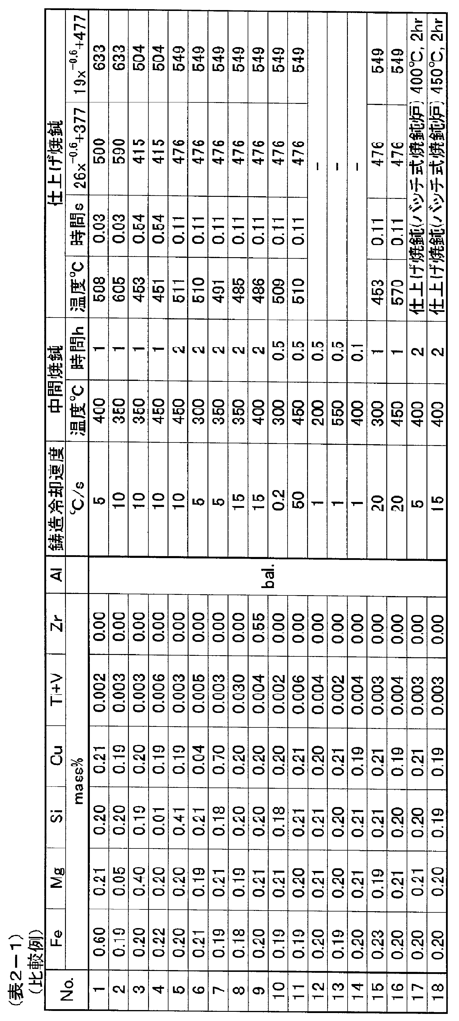

表1-1、表1-2、表2-1及び表2-2の結果から以下のことが分かる。
比較例1~9ではアルミニウム合金の添加成分が本発明の範囲外である。比較例1では、Feが多すぎるため、金属間化合物A及びBが多く、加工性、繰返破断回数、引張破断伸びが悪い。比較例2は、Mgが少なすぎるため、金属間化合物Cが少なく、引張強度、繰返破断回数が悪い。比較例3は、Mgが多すぎるため、金属間化合物Cが多く、加工性、繰返破断回数が悪い。比較例4は、Siが少なすぎるため、金属間化合物Cが少なく、引張強度、繰返破断回数が悪い。比較例5は、Siが多すぎるため、金属間化合物Bが多く、加工性、繰返破断回数が悪い。比較例6は、Cuが少なすぎるため、引張強度、繰返破断回数が悪い。比較例7は、Cuが多すぎるため、金属間化合物Bが多く、加工性、導電率が悪い。比較例8は、TiとVの合計量が多すぎるため、加工性、繰返破断回数、導電率が悪い。比較例9は、Zrが多すぎるため、金属間化合物Bが多く、加工性、繰返破断回数が悪い。
比較例10~18は、アルミニウム合金導体中の金属間化合物の面積率が本発明の範囲外であるか、製造中に断線したものを示す。ここでは、アルミニウム合金の製造条件によって本発明の規定するアルミニウム合金導体が得られなかった例を示す。比較例10は、鋳造冷却速度が遅すぎて、金属間化合物Aが多すぎるため、加工性、繰返破断回数、引張破断伸びが悪い。比較例11は、金属間化合物Bが多すぎるため、加工性、繰返破断回数が悪く、鋳造冷却速度が速すぎるため、導電率が悪い。比較例12~14では、仕上げ焼鈍を行わなかったために、いずれも伸線工程で断線した。比較例15は、仕上げ焼鈍工程での軟化不足が原因で未焼鈍状態となり、金属間化合物が観察されなかったため、加工性、引張破断伸びが悪い。比較例16は、仕上げ焼鈍温度が高すぎることにより金属間化合物Cが少なすぎるため、加工性、引張強度、繰返破断回数、引張破断伸びが悪い。比較例17~18は、仕上げ焼鈍をバッチ焼鈍とした結果、金属間化合物Cが少なすぎるため、繰返破断回数が悪い。
これに対し実施例1~27では、加工性が良好で、繰返破断回数(耐屈曲疲労特性)、引張破断伸び(柔軟性)、引張強度、及び導電率に優れたアルミニウム合金導体が得られた。 The following can be understood from the results of Table 1-1, Table 1-2, Table 2-1, and Table 2-2.
In Comparative Examples 1 to 9, the additive component of the aluminum alloy is outside the scope of the present invention. In comparative example 1, since there is too much Fe, there are many intermetallic compounds A and B, and workability, the number of times of repeated fracture, and tensile elongation at break are bad. In Comparative Example 2, since the amount of Mg is too small, the intermetallic compound C is small, and the tensile strength and the number of repeated fractures are poor. Since the comparative example 3 has too much Mg, there are many intermetallic compounds C, and workability and the number of repeated fractures are bad. In Comparative Example 4, since there is too little Si, the intermetallic compound C is small, and the tensile strength and the number of repeated fractures are poor. Since the comparative example 5 has too much Si, there are many intermetallic compounds B, and workability and the number of repeated fractures are bad. Since the comparative example 6 has too little Cu, the tensile strength and the number of repeated fractures are poor. Since the comparative example 7 has too much Cu, there are many intermetallic compounds B, and workability and electrical conductivity are bad. Since the comparative example 8 has too much total amount of Ti and V, workability, the number of repeated fractures, and electrical conductivity are bad. Since the comparative example 9 has too much Zr, there are many intermetallic compounds B, and workability and the number of repeated fractures are bad.
Comparative Examples 10 to 18 show that the area ratio of the intermetallic compound in the aluminum alloy conductor is out of the range of the present invention or is broken during the production. Here, an example is shown in which the aluminum alloy conductor defined by the present invention is not obtained depending on the production conditions of the aluminum alloy. In Comparative Example 10, since the casting cooling rate is too slow and the intermetallic compound A is too much, the workability, the number of repeated fractures, and the tensile elongation at break are poor. In Comparative Example 11, since the intermetallic compound B is too much, the workability and the number of repeated fractures are poor, and the casting cooling rate is too fast, so the conductivity is bad. In Comparative Examples 12 to 14, since the finish annealing was not performed, all were disconnected in the wire drawing process. Comparative Example 15 was unannealed due to insufficient softening in the final annealing step, and no intermetallic compound was observed, so that workability and tensile elongation at break were poor. In Comparative Example 16, because the finish annealing temperature is too high, the amount of intermetallic compound C is too small, so that workability, tensile strength, number of repeated breaks, and tensile break elongation are poor. In Comparative Examples 17 to 18, the number of repeated fractures is poor because the intermetallic compound C is too small as a result of batch annealing as the final annealing.
On the other hand, in Examples 1 to 27, an aluminum alloy conductor having excellent workability and excellent in the number of repeated fractures (flexural fatigue resistance), tensile elongation at break (flexibility), tensile strength, and conductivity was obtained. It was.
本発明をその実施態様とともに説明したが、我々は特に指定しない限り我々の発明を説明のどの細部においても限定しようとするものではなく、添付の請求の範囲に示した発明の精神と範囲に反することなく幅広く解釈されるべきであると考える。
While this invention has been described in conjunction with its embodiments, we do not intend to limit our invention in any detail of the description unless otherwise specified and are contrary to the spirit and scope of the invention as set forth in the appended claims. I think it should be interpreted widely.
本願は、2010年2月26日に日本国で特許出願された特願2010-043487に基づく優先権を主張するものであり、これはここに参照してその内容を本明細書の記載の一部として取り込む。
This application claims priority based on Japanese Patent Application No. 2010-043487, filed in Japan on February 26, 2010, which is hereby incorporated herein by reference. Capture as part.
1 試験片(線材)
2、3 曲げ治具
4 重り
5、51、52 押さえ冶具 1 Test piece (wire)
2, 3 Bending jig 4 Weight 5, 51, 52 Holding jig
2、3 曲げ治具
4 重り
5、51、52 押さえ冶具 1 Test piece (wire)
2, 3 Bending jig 4 Weight 5, 51, 52 Holding jig
Claims (8)
- Feを0.01~0.4mass%と、Mgを0.1~0.3mass%と、Siを0.04~0.3mass%と、Cuを0.1~0.5mass%とを含有し、さらにTiとVを合わせて0.001~0.01mass%含み、残部Alと不可避不純物からなるアルミニウム合金導体であって、
前記導体中に3種類の金属間化合物A、B、Cが存在し、
前記金属間化合物Aの粒子径は0.1μm以上2μm以下の範囲であり、
前記金属間化合物Bの粒子径は0.03μm以上0.1μm未満の範囲であり、
前記金属間化合物Cの粒子径は0.001μm以上0.03μm未満の範囲であり、
前記導体中の任意の範囲における、前記金属間化合物Aの面積率a、前記金属間化合物Bの面積率b、および前記金属間化合物Cの面積率cが、それぞれ0.1% ≦ a ≦ 2.5%、0.1% ≦ b ≦ 3%、1% ≦ c ≦ 10%を満足することを特徴とするアルミニウム合金導体。 Fe contains 0.01 to 0.4 mass%, Mg 0.1 to 0.3 mass%, Si 0.04 to 0.3 mass%, and Cu 0.1 to 0.5 mass%. In addition, an aluminum alloy conductor comprising 0.001 to 0.01 mass% of Ti and V combined, the balance being Al and inevitable impurities,
There are three types of intermetallic compounds A, B, C in the conductor,
The particle size of the intermetallic compound A is in the range of 0.1 μm to 2 μm,
The particle size of the intermetallic compound B is in the range of 0.03 μm or more and less than 0.1 μm,
The particle size of the intermetallic compound C is in the range of 0.001 μm or more and less than 0.03 μm,
The area ratio a of the intermetallic compound A, the area ratio b of the intermetallic compound B, and the area ratio c of the intermetallic compound C in an arbitrary range in the conductor are 0.1% ≦ a ≦ 2, respectively. An aluminum alloy conductor characterized by satisfying .5%, 0.1% .ltoreq.b.ltoreq.3%, 1% .ltoreq.c.ltoreq.10%. - Feを0.01~0.4mass%と、Mgを0.1~0.3mass%と、Siを0.04~0.3mass%と、Cuを0.1~0.5mass%と、Zrを0.01~0.4mass%とを含有し、さらにTiとVを合わせて0.001~0.01mass%含み、残部Alと不可避不純物からなるアルミニウム合金導体であって、
前記導体中に3種類の金属間化合物A、B、Cが存在し、
前記金属間化合物Aの粒子径は0.1μm以上2μm以下の範囲であり、
前記金属間化合物Bの粒子径は0.03μm以上0.1μm未満の範囲であり、
前記金属間化合物Cの粒子径は0.001μm以上0.03μm未満の範囲であり、
前記導体中の任意の範囲における、前記金属間化合物Aの面積率a、前記金属間化合物Bの面積率b、および前記金属間化合物Cの面積率cが、それぞれ0.1% ≦ a ≦ 2.5%、0.1% ≦ b ≦ 5.5%、1% ≦ c ≦ 10%を満足することを特徴とするアルミニウム合金導体。 Fe is 0.01 to 0.4 mass%, Mg is 0.1 to 0.3 mass%, Si is 0.04 to 0.3 mass%, Cu is 0.1 to 0.5 mass%, and Zr is An aluminum alloy conductor containing 0.01 to 0.4 mass%, further including 0.001 to 0.01 mass% of Ti and V in combination, the balance being Al and inevitable impurities,
There are three types of intermetallic compounds A, B, C in the conductor,
The particle size of the intermetallic compound A is in the range of 0.1 μm to 2 μm,
The particle size of the intermetallic compound B is in the range of 0.03 μm or more and less than 0.1 μm,
The particle size of the intermetallic compound C is in the range of 0.001 μm or more and less than 0.03 μm,
The area ratio a of the intermetallic compound A, the area ratio b of the intermetallic compound B, and the area ratio c of the intermetallic compound C in an arbitrary range in the conductor are 0.1% ≦ a ≦ 2, respectively. An aluminum alloy conductor characterized by satisfying .5%, 0.1% .ltoreq.b.ltoreq.5.5%, 1% .ltoreq.c.ltoreq.10%. - 前記導体の製造工程の最後に急熱、急冷の工程を含む連続通電熱処理が施されることにより、伸線方向の垂直断面における結晶粒径が1~30μmとなされる、請求項1または請求項2に記載のアルミニウム合金導体。 The crystal grain size in a vertical cross section in the wire drawing direction is set to 1 to 30 μm by performing continuous energization heat treatment including rapid heating and rapid cooling processes at the end of the manufacturing process of the conductor. 2. The aluminum alloy conductor according to 2.
- 引張強度が100MPa以上、及び導電率が55%IACS以上である請求項1~3のいずれか1項に記載のアルミニウム合金導体。 The aluminum alloy conductor according to any one of claims 1 to 3, having a tensile strength of 100 MPa or more and an electrical conductivity of 55% IACS or more.
- 引張破断伸びが10%以上である請求項1~4のいずれか1項に記載のアルミニウム合金導体。 The aluminum alloy conductor according to any one of claims 1 to 4, which has a tensile elongation at break of 10% or more.
- 再結晶組織を有する請求項1~5のいずれか1項に記載のアルミニウム合金導体。 The aluminum alloy conductor according to any one of claims 1 to 5, which has a recrystallized structure.
- 前記導体が移動体内で、バッテリーケーブル、ハーネス、またはモータ用線材として用いられることを特徴とする請求項1~6のいずれか1項に記載のアルミニウム合金導体。 The aluminum alloy conductor according to any one of claims 1 to 6, wherein the conductor is used as a battery cable, a harness, or a wire for a motor in a moving body.
- 前記導体が車両、電車、または航空機に用いられることを特徴とする請求項1~7のいずれか1項に記載のアルミニウム合金導体。 The aluminum alloy conductor according to any one of claims 1 to 7, wherein the conductor is used in a vehicle, a train, or an aircraft.
Priority Applications (4)
| Application Number | Priority Date | Filing Date | Title |
|---|---|---|---|
| EP11747540.0A EP2540848B1 (en) | 2010-02-26 | 2011-02-25 | Aluminum alloy conductor |
| JP2011528126A JP4986251B2 (en) | 2010-02-26 | 2011-02-25 | Aluminum alloy conductor |
| CN201180010670.6A CN102803530B (en) | 2010-02-26 | 2011-02-25 | Aluminum alloy conductor |
| US13/594,419 US9214251B2 (en) | 2010-02-26 | 2012-08-24 | Aluminum alloy conductor |
Applications Claiming Priority (2)
| Application Number | Priority Date | Filing Date | Title |
|---|---|---|---|
| JP2010-043487 | 2010-02-26 | ||
| JP2010043487 | 2010-02-26 |
Related Child Applications (1)
| Application Number | Title | Priority Date | Filing Date |
|---|---|---|---|
| US13/594,419 Continuation US9214251B2 (en) | 2010-02-26 | 2012-08-24 | Aluminum alloy conductor |
Publications (1)
| Publication Number | Publication Date |
|---|---|
| WO2011105584A1 true WO2011105584A1 (en) | 2011-09-01 |
Family
ID=44506981
Family Applications (1)
| Application Number | Title | Priority Date | Filing Date |
|---|---|---|---|
| PCT/JP2011/054397 WO2011105584A1 (en) | 2010-02-26 | 2011-02-25 | Aluminum alloy conductor |
Country Status (5)
| Country | Link |
|---|---|
| US (1) | US9214251B2 (en) |
| EP (1) | EP2540848B1 (en) |
| JP (1) | JP4986251B2 (en) |
| CN (1) | CN102803530B (en) |
| WO (1) | WO2011105584A1 (en) |
Cited By (13)
| Publication number | Priority date | Publication date | Assignee | Title |
|---|---|---|---|---|
| WO2012008588A1 (en) * | 2010-07-15 | 2012-01-19 | 古河電気工業株式会社 | Aluminum alloy conductor |
| WO2012011513A1 (en) * | 2010-07-20 | 2012-01-26 | 古河電気工業株式会社 | Aluminium alloy conductor and manufacturing method for same |
| WO2012011447A1 (en) * | 2010-07-20 | 2012-01-26 | 古河電気工業株式会社 | Aluminium alloy conductor and manufacturing method for same |
| CN102978491A (en) * | 2012-12-24 | 2013-03-20 | 郝相臣 | High-conductivity aluminium alloy conductor material for cables and preparation method thereof |
| WO2013146762A1 (en) * | 2012-03-29 | 2013-10-03 | 大電株式会社 | Microcrystal metal conductor and method for manufacturing same |
| JP2015021156A (en) * | 2013-07-18 | 2015-02-02 | 株式会社フジクラ | METHOD FOR MANUFACTURING Al ALLOY CONDUCTIVE WIRE |
| JP2015096645A (en) * | 2013-11-15 | 2015-05-21 | 古河電気工業株式会社 | Aluminum alloy conductor, aluminum alloy strand wire, coated electric wire and wire harness |
| EP2832874A4 (en) * | 2012-03-29 | 2015-11-25 | Furukawa Electric Co Ltd | Aluminum alloy wire and process for producing same |
| WO2016047627A1 (en) * | 2014-09-22 | 2016-03-31 | 古河電気工業株式会社 | Terminal-equipped electrical wire |
| JP2019196519A (en) * | 2018-05-09 | 2019-11-14 | 日立金属株式会社 | Aluminum alloy wire and method for producing the same |
| JP2019196520A (en) * | 2018-05-09 | 2019-11-14 | 日立金属株式会社 | Aluminum alloy wire and method for producing the same |
| JP2021155828A (en) * | 2020-03-30 | 2021-10-07 | 電源開発株式会社 | Aluminum alloy wire and electric wire |
| EP3611800B1 (en) * | 2018-08-13 | 2022-02-16 | Hitachi Metals, Ltd. | Terminal-equipped electric wire |
Families Citing this family (10)
| Publication number | Priority date | Publication date | Assignee | Title |
|---|---|---|---|---|
| EP2907884B1 (en) * | 2012-10-11 | 2018-05-09 | UACJ Corporation | Plate-like conductor for bus bar, and bus bar comprising same |
| JP5607854B1 (en) | 2013-03-29 | 2014-10-15 | 古河電気工業株式会社 | Aluminum alloy wire, aluminum alloy stranded wire, covered electric wire, wire harness, and aluminum alloy wire manufacturing method |
| CN104781433B (en) * | 2013-03-29 | 2017-07-07 | 古河电器工业株式会社 | The manufacture method of aluminium alloy conductor, aluminium alloy stranded conductor, coated electric wire, wire harness and aluminium alloy conductor |
| EP3260563B1 (en) * | 2013-03-29 | 2019-04-24 | Furukawa Electric Co. Ltd. | Aluminum alloy conductor, aluminum alloy stranded wire, coated wire, wire harness, and manufacturing method of aluminum alloy conductor |
| JP6396067B2 (en) | 2014-04-10 | 2018-09-26 | 株式会社Uacj | Aluminum alloy plate for bus bar and manufacturing method thereof |
| WO2015182624A1 (en) | 2014-05-26 | 2015-12-03 | 古河電気工業株式会社 | Aluminum alloy conductor wire, aluminum alloy twisted wire, sheathed electrical cable, wire harness, and method for manufacturing aluminum alloy conductor wire |
| US10553327B2 (en) | 2014-05-26 | 2020-02-04 | Furukawa Electric Co., Ltd. | Aluminum alloy conductor wire, aluminum alloy stranded wire, coated wire, wire harness and method of manufacturing aluminum alloy conductor wire |
| CN104975246A (en) * | 2015-05-15 | 2015-10-14 | 重庆泰山电缆有限公司 | Method for manufacturing high-conductivity flexible aluminum type wire |
| KR20220033650A (en) * | 2020-09-09 | 2022-03-17 | 삼성디스플레이 주식회사 | Reflective electrode and display device having the same |
| US12088029B2 (en) * | 2021-07-20 | 2024-09-10 | Dell Products L.P. | Cable termination for information handling systems |
Citations (9)
| Publication number | Priority date | Publication date | Assignee | Title |
|---|---|---|---|---|
| JPS4943162B1 (en) * | 1970-05-06 | 1974-11-19 | ||
| JPS5545626B2 (en) | 1976-12-27 | 1980-11-19 | ||
| JP2001254160A (en) * | 2000-03-09 | 2001-09-18 | Mitsubishi Cable Ind Ltd | Method of manufacturing aluminum alloy wire, and aluminum alloy |
| JP2005174554A (en) * | 2003-12-05 | 2005-06-30 | Furukawa Electric Co Ltd:The | Aluminum conductive wire |
| JP2006019163A (en) | 2004-07-02 | 2006-01-19 | Furukawa Electric Co Ltd:The | Aluminum conductive wire |
| JP2006253109A (en) | 2005-02-08 | 2006-09-21 | Furukawa Electric Co Ltd:The | Aluminum conductive wire |
| JP2008112620A (en) | 2006-10-30 | 2008-05-15 | Auto Network Gijutsu Kenkyusho:Kk | Electric wire conductor and its manufacturing method |
| JP2010043487A (en) | 2008-08-14 | 2010-02-25 | Funabashi Kenchiku Sekkei Jimusho:Kk | Mat foundation form of corner part |
| WO2010082671A1 (en) * | 2009-01-19 | 2010-07-22 | 古河電気工業株式会社 | Aluminum alloy wire |
Family Cites Families (8)
| Publication number | Priority date | Publication date | Assignee | Title |
|---|---|---|---|---|
| GB1057152A (en) * | 1963-06-12 | 1967-02-01 | Furukawa Electric Co Ltd | Aluminium alloys for electric conductors |
| US3670401A (en) * | 1970-04-01 | 1972-06-20 | Southwire Co | Method of fabricating aluminum alloy rod |
| US3663216A (en) * | 1970-08-10 | 1972-05-16 | Aluminum Co Of America | Aluminum electrical conductor |
| GB1524355A (en) * | 1975-10-31 | 1978-09-13 | Alcan Res & Dev | Aluminium alloy sheet products |
| JPH0823609A (en) * | 1994-07-07 | 1996-01-23 | Toshiba Corp | System for inspecting field apparatus |
| EP0968315B1 (en) * | 1997-03-21 | 2001-11-14 | Alcan International Limited | Al-Mg-Si ALLOY WITH GOOD EXTRUSION PROPERTIES |
| JP5188115B2 (en) * | 2007-07-19 | 2013-04-24 | 古河スカイ株式会社 | High strength aluminum alloy brazing sheet |
| JP4787885B2 (en) * | 2008-08-11 | 2011-10-05 | 住友電気工業株式会社 | Wire harness for wire harness and wire harness for automobile |
-
2011
- 2011-02-25 WO PCT/JP2011/054397 patent/WO2011105584A1/en active Application Filing
- 2011-02-25 EP EP11747540.0A patent/EP2540848B1/en active Active
- 2011-02-25 JP JP2011528126A patent/JP4986251B2/en active Active
- 2011-02-25 CN CN201180010670.6A patent/CN102803530B/en active Active
-
2012
- 2012-08-24 US US13/594,419 patent/US9214251B2/en active Active
Patent Citations (9)
| Publication number | Priority date | Publication date | Assignee | Title |
|---|---|---|---|---|
| JPS4943162B1 (en) * | 1970-05-06 | 1974-11-19 | ||
| JPS5545626B2 (en) | 1976-12-27 | 1980-11-19 | ||
| JP2001254160A (en) * | 2000-03-09 | 2001-09-18 | Mitsubishi Cable Ind Ltd | Method of manufacturing aluminum alloy wire, and aluminum alloy |
| JP2005174554A (en) * | 2003-12-05 | 2005-06-30 | Furukawa Electric Co Ltd:The | Aluminum conductive wire |
| JP2006019163A (en) | 2004-07-02 | 2006-01-19 | Furukawa Electric Co Ltd:The | Aluminum conductive wire |
| JP2006253109A (en) | 2005-02-08 | 2006-09-21 | Furukawa Electric Co Ltd:The | Aluminum conductive wire |
| JP2008112620A (en) | 2006-10-30 | 2008-05-15 | Auto Network Gijutsu Kenkyusho:Kk | Electric wire conductor and its manufacturing method |
| JP2010043487A (en) | 2008-08-14 | 2010-02-25 | Funabashi Kenchiku Sekkei Jimusho:Kk | Mat foundation form of corner part |
| WO2010082671A1 (en) * | 2009-01-19 | 2010-07-22 | 古河電気工業株式会社 | Aluminum alloy wire |
Cited By (21)
| Publication number | Priority date | Publication date | Assignee | Title |
|---|---|---|---|---|
| WO2012008588A1 (en) * | 2010-07-15 | 2012-01-19 | 古河電気工業株式会社 | Aluminum alloy conductor |
| WO2012011513A1 (en) * | 2010-07-20 | 2012-01-26 | 古河電気工業株式会社 | Aluminium alloy conductor and manufacturing method for same |
| WO2012011447A1 (en) * | 2010-07-20 | 2012-01-26 | 古河電気工業株式会社 | Aluminium alloy conductor and manufacturing method for same |
| JP2016180186A (en) * | 2012-03-29 | 2016-10-13 | 大電株式会社 | Production method of microcrystal metal conductor, and microcrystal metal conductor |
| WO2013146762A1 (en) * | 2012-03-29 | 2013-10-03 | 大電株式会社 | Microcrystal metal conductor and method for manufacturing same |
| US9580784B2 (en) | 2012-03-29 | 2017-02-28 | Furukawa Automotive Systems Inc. | Aluminum alloy wire and method of producing the same |
| EP2832874A4 (en) * | 2012-03-29 | 2015-11-25 | Furukawa Electric Co Ltd | Aluminum alloy wire and process for producing same |
| JPWO2013146762A1 (en) * | 2012-03-29 | 2015-12-14 | 大電株式会社 | Microcrystalline metal conductor and method for producing the same |
| CN102978491A (en) * | 2012-12-24 | 2013-03-20 | 郝相臣 | High-conductivity aluminium alloy conductor material for cables and preparation method thereof |
| JP2015021156A (en) * | 2013-07-18 | 2015-02-02 | 株式会社フジクラ | METHOD FOR MANUFACTURING Al ALLOY CONDUCTIVE WIRE |
| JP2015096645A (en) * | 2013-11-15 | 2015-05-21 | 古河電気工業株式会社 | Aluminum alloy conductor, aluminum alloy strand wire, coated electric wire and wire harness |
| WO2016047627A1 (en) * | 2014-09-22 | 2016-03-31 | 古河電気工業株式会社 | Terminal-equipped electrical wire |
| JPWO2016047627A1 (en) * | 2014-09-22 | 2017-07-06 | 古河電気工業株式会社 | Electric wire with terminal |
| US9899119B2 (en) | 2014-09-22 | 2018-02-20 | Furukawa Electric Co., Ltd. | Electric wire apparatus |
| JP2019196519A (en) * | 2018-05-09 | 2019-11-14 | 日立金属株式会社 | Aluminum alloy wire and method for producing the same |
| JP2019196520A (en) * | 2018-05-09 | 2019-11-14 | 日立金属株式会社 | Aluminum alloy wire and method for producing the same |
| JP7167478B2 (en) | 2018-05-09 | 2022-11-09 | 日立金属株式会社 | Aluminum alloy wire rod and manufacturing method thereof |
| JP7167479B2 (en) | 2018-05-09 | 2022-11-09 | 日立金属株式会社 | Aluminum alloy wire rod and manufacturing method thereof |
| EP3611800B1 (en) * | 2018-08-13 | 2022-02-16 | Hitachi Metals, Ltd. | Terminal-equipped electric wire |
| JP2021155828A (en) * | 2020-03-30 | 2021-10-07 | 電源開発株式会社 | Aluminum alloy wire and electric wire |
| JP7398315B2 (en) | 2020-03-30 | 2023-12-14 | 電源開発株式会社 | Aluminum alloy wire and electric wire |
Also Published As
| Publication number | Publication date |
|---|---|
| JP4986251B2 (en) | 2012-07-25 |
| EP2540848B1 (en) | 2018-05-23 |
| CN102803530B (en) | 2014-08-20 |
| EP2540848A4 (en) | 2013-11-06 |
| US9214251B2 (en) | 2015-12-15 |
| US20120321889A1 (en) | 2012-12-20 |
| CN102803530A (en) | 2012-11-28 |
| JPWO2011105584A1 (en) | 2013-06-20 |
| EP2540848A1 (en) | 2013-01-02 |
Similar Documents
| Publication | Publication Date | Title |
|---|---|---|
| JP4986251B2 (en) | Aluminum alloy conductor | |
| JP4986252B2 (en) | Aluminum alloy conductor | |
| JP5367926B1 (en) | Aluminum alloy wire and manufacturing method thereof | |
| JP5193374B2 (en) | Aluminum alloy conductor and method for producing the same | |
| JP5193375B2 (en) | Method for producing aluminum alloy conductor | |
| JP5607855B1 (en) | Aluminum alloy wire, aluminum alloy stranded wire, covered electric wire, wire harness, and aluminum alloy wire manufacturing method | |
| US8951370B2 (en) | Aluminum alloy wire material | |
| JP5184719B2 (en) | Aluminum alloy conductor | |
| KR20150140709A (en) | Aluminum alloy conductor, alum1inum alloy stranded wire, sheathed wire, wire harness, and method for manufacturing aluminum alloy conductor | |
| JP2013044038A (en) | Aluminum alloy conductor | |
| JP6440476B2 (en) | Aluminum alloy wire, aluminum alloy twisted wire, covered electric wire and wire harness, and method for producing aluminum alloy wire | |
| JP5939530B2 (en) | Aluminum alloy conductor | |
| JP5228118B2 (en) | Method for producing aluminum alloy conductor | |
| JP4986253B2 (en) | Aluminum alloy conductor |
Legal Events
| Date | Code | Title | Description |
|---|---|---|---|
| WWE | Wipo information: entry into national phase |
Ref document number: 201180010670.6 Country of ref document: CN |
|
| WWE | Wipo information: entry into national phase |
Ref document number: 2011528126 Country of ref document: JP |
|
| 121 | Ep: the epo has been informed by wipo that ep was designated in this application |
Ref document number: 11747540 Country of ref document: EP Kind code of ref document: A1 |
|
| NENP | Non-entry into the national phase |
Ref country code: DE |
|
| WWE | Wipo information: entry into national phase |
Ref document number: 2011747540 Country of ref document: EP |