WO2011105540A1 - 複合材の修理方法およびこれを用いた複合材 - Google Patents
複合材の修理方法およびこれを用いた複合材 Download PDFInfo
- Publication number
- WO2011105540A1 WO2011105540A1 PCT/JP2011/054257 JP2011054257W WO2011105540A1 WO 2011105540 A1 WO2011105540 A1 WO 2011105540A1 JP 2011054257 W JP2011054257 W JP 2011054257W WO 2011105540 A1 WO2011105540 A1 WO 2011105540A1
- Authority
- WO
- WIPO (PCT)
- Prior art keywords
- composite material
- needle
- repairing
- staple
- coupling member
- Prior art date
Links
Images


Classifications
-
- B—PERFORMING OPERATIONS; TRANSPORTING
- B29—WORKING OF PLASTICS; WORKING OF SUBSTANCES IN A PLASTIC STATE IN GENERAL
- B29C—SHAPING OR JOINING OF PLASTICS; SHAPING OF MATERIAL IN A PLASTIC STATE, NOT OTHERWISE PROVIDED FOR; AFTER-TREATMENT OF THE SHAPED PRODUCTS, e.g. REPAIRING
- B29C73/00—Repairing of articles made from plastics or substances in a plastic state, e.g. of articles shaped or produced by using techniques covered by this subclass or subclass B29D
- B29C73/04—Repairing of articles made from plastics or substances in a plastic state, e.g. of articles shaped or produced by using techniques covered by this subclass or subclass B29D using preformed elements
-
- B—PERFORMING OPERATIONS; TRANSPORTING
- B29—WORKING OF PLASTICS; WORKING OF SUBSTANCES IN A PLASTIC STATE IN GENERAL
- B29C—SHAPING OR JOINING OF PLASTICS; SHAPING OF MATERIAL IN A PLASTIC STATE, NOT OTHERWISE PROVIDED FOR; AFTER-TREATMENT OF THE SHAPED PRODUCTS, e.g. REPAIRING
- B29C65/00—Joining or sealing of preformed parts, e.g. welding of plastics materials; Apparatus therefor
- B29C65/56—Joining or sealing of preformed parts, e.g. welding of plastics materials; Apparatus therefor using mechanical means or mechanical connections, e.g. form-fits
-
- B—PERFORMING OPERATIONS; TRANSPORTING
- B29—WORKING OF PLASTICS; WORKING OF SUBSTANCES IN A PLASTIC STATE IN GENERAL
- B29C—SHAPING OR JOINING OF PLASTICS; SHAPING OF MATERIAL IN A PLASTIC STATE, NOT OTHERWISE PROVIDED FOR; AFTER-TREATMENT OF THE SHAPED PRODUCTS, e.g. REPAIRING
- B29C73/00—Repairing of articles made from plastics or substances in a plastic state, e.g. of articles shaped or produced by using techniques covered by this subclass or subclass B29D
- B29C73/04—Repairing of articles made from plastics or substances in a plastic state, e.g. of articles shaped or produced by using techniques covered by this subclass or subclass B29D using preformed elements
- B29C73/06—Repairing of articles made from plastics or substances in a plastic state, e.g. of articles shaped or produced by using techniques covered by this subclass or subclass B29D using preformed elements using plugs sealing in the hole
-
- B—PERFORMING OPERATIONS; TRANSPORTING
- B64—AIRCRAFT; AVIATION; COSMONAUTICS
- B64F—GROUND OR AIRCRAFT-CARRIER-DECK INSTALLATIONS SPECIALLY ADAPTED FOR USE IN CONNECTION WITH AIRCRAFT; DESIGNING, MANUFACTURING, ASSEMBLING, CLEANING, MAINTAINING OR REPAIRING AIRCRAFT, NOT OTHERWISE PROVIDED FOR; HANDLING, TRANSPORTING, TESTING OR INSPECTING AIRCRAFT COMPONENTS, NOT OTHERWISE PROVIDED FOR
- B64F5/00—Designing, manufacturing, assembling, cleaning, maintaining or repairing aircraft, not otherwise provided for; Handling, transporting, testing or inspecting aircraft components, not otherwise provided for
- B64F5/40—Maintaining or repairing aircraft
-
- Y—GENERAL TAGGING OF NEW TECHNOLOGICAL DEVELOPMENTS; GENERAL TAGGING OF CROSS-SECTIONAL TECHNOLOGIES SPANNING OVER SEVERAL SECTIONS OF THE IPC; TECHNICAL SUBJECTS COVERED BY FORMER USPC CROSS-REFERENCE ART COLLECTIONS [XRACs] AND DIGESTS
- Y10—TECHNICAL SUBJECTS COVERED BY FORMER USPC
- Y10T—TECHNICAL SUBJECTS COVERED BY FORMER US CLASSIFICATION
- Y10T29/00—Metal working
- Y10T29/49—Method of mechanical manufacture
- Y10T29/49718—Repairing
- Y10T29/49732—Repairing by attaching repair preform, e.g., remaking, restoring, or patching
-
- Y—GENERAL TAGGING OF NEW TECHNOLOGICAL DEVELOPMENTS; GENERAL TAGGING OF CROSS-SECTIONAL TECHNOLOGIES SPANNING OVER SEVERAL SECTIONS OF THE IPC; TECHNICAL SUBJECTS COVERED BY FORMER USPC CROSS-REFERENCE ART COLLECTIONS [XRACs] AND DIGESTS
- Y10—TECHNICAL SUBJECTS COVERED BY FORMER USPC
- Y10T—TECHNICAL SUBJECTS COVERED BY FORMER US CLASSIFICATION
- Y10T428/00—Stock material or miscellaneous articles
- Y10T428/249921—Web or sheet containing structurally defined element or component
- Y10T428/249923—Including interlaminar mechanical fastener
Definitions
- the present invention relates to a method for repairing a composite material used as a structural material for an aircraft or the like and a composite material using the same, and more particularly, to bonding of a separation gap generated between layers of a cured composite material.
- JP 7-137154 A Japanese Patent No. 2541620 JP-A-3-297629 Japanese Patent Laid-Open No. 2-74325 Japanese Patent Laid-Open No. 3-286841
- Patent Document 1 has a problem that the resin cannot be injected when the separation gap generated between the layers of the composite material is small. Furthermore, the inventions of Patent Document 1 and Patent Document 2 have a problem that the time required for repair becomes long because it is difficult to manage each process of cleaning, drying, and bonding.
- the invention described in Patent Document 3 is limited to thermoplastic composite materials, and has a problem that it cannot be applied to repair of thermosetting composite materials that cannot be softened by reheating after curing. Further, the inventions described in Patent Document 4 and Patent Document 5 can be applied only to the soft stage before the composite material layer is cured, and cannot be applied to repair of a completely cured composite material.
- the present invention has been made in view of such circumstances, and a method for repairing a composite material capable of easily and quickly repairing a peeling gap generated between layers of a cured composite material, and the same It aims at providing the composite material using this.
- the composite material repair method of the present invention and the composite material using the same employ the following means. That is, according to the method for repairing a composite material according to the first aspect of the present invention, a hole penetrating through a separation gap formed between layers of the cured composite material is provided, and a coupling member is inserted into the hole to perform the separation. Join the gap.
- a sleeve may be inserted into the hole, and the coupling member may penetrate the sleeve.
- a sleeve was inserted into the hole provided in the separation gap, and the coupling member was allowed to penetrate after the sleeve was inserted.
- the end portion of the coupling member that penetrates the hole may be subjected to bending.
- the end of the coupling member that penetrated the hole was bent by bending. Therefore, it is possible to prevent loosening of the coupling member coupled with the peeling gap. Therefore, it is possible to firmly bond the separation gap generated between the layers of the cured composite material.
- the end portion of the coupling member penetrating the hole may be caulked by a caulking portion.
- the end of the coupling member that penetrated the hole was caulked by the caulking portion. Therefore, it is possible to prevent loosening of the coupling member coupled with the separation gap, compared to the case where the caulking portion is not provided. Therefore, it is possible to further strengthen the bond of the separation gap generated between the layers of the cured composite material.
- the end portion of the coupling member penetrating the hole may be covered with a seal portion.
- an anti-corrosion material may be provided between the coupling member and the composite material layer.
- the coupling member may have a quadrangular cross-sectional shape.
- the coupling member may be a staple needle having a plurality of needle feet.
- Staple needles having a plurality of needle feet were used. Therefore, it is possible to make the bond of the separation gap generated between the layers of the composite material more firm. In addition, it is not necessary to combine the separation gaps using a large number of staples, and it is possible to shorten the time for combining the separation gaps.
- the number of the needle feet may be four, and each needle foot may be provided on each side of the rectangular staple needle body.
- the coupling member may be a staple needle having a needle foot of a composite material fiber impregnated with a thermoplastic resin or a thermosetting resin.
- the needle tips were joined together by curing the resin using a staple needle having a needle foot. Therefore, the needle becomes a single ring, and the bond of the separation gap generated between the layers of the composite material can be made stronger. Further, there is no need to worry about the occurrence of electrolytic corrosion as in the case of using a metal staple, and it is possible to prevent the composite material and the coupling member from deteriorating.
- the coupling member may be a blind rivet.
- blind rivets were used for the connecting members. As a result, the blind rivet can be penetrated into the hole and caulked. For this reason, the coupling can be performed more easily than when a staple is used. Therefore, it is possible to shorten the repair time of the peeling gap generated between the layers of the cured composite material.
- the coupling member may be provided with a surface coating for preventing electrolytic corrosion.
- a bonding member having a surface coating for preventing electrolytic corrosion was used. Therefore, the occurrence of electrolytic corrosion can be prevented without providing a sleeve or the like. Therefore, it is possible to easily repair the peeling gap generated between the layers of the cured composite material, and to shorten the repair time. Further, since the sleeve is not provided, the hole diameter provided in the composite material may be small. Therefore, it is not necessary to break the fibers of the composite material by drilling. Therefore, the hole processing is simple, and at the same time, the influence of the decrease in the strength of the fiber of the composite material can be suppressed.
- the coupling member may be made of a shape memory alloy.
- the shape memory alloy was used as the material for the coupling member. Therefore, the coupling member can be formed in a predetermined shape according to the temperature change. Therefore, by setting the temperature to a predetermined value, it is possible to easily repair and bond the peeling gap generated between the layers of the cured composite material in a short time.
- the composite material may be repaired by the composite material repair method according to any of the above aspects.
- FIG. 1B is a cross-sectional view taken along a line AA in FIG. 1A. It is explanatory drawing of the repair method of the peeling clearance gap which arose between the layers of the composite material. It is explanatory drawing of the repair method of the peeling clearance gap which arose between the layers of the composite material. It is explanatory drawing of the repair method of the peeling clearance gap which arose between the layers of the composite material. It is explanatory drawing of the repair method of the peeling clearance gap which arose between the layers of the composite material.
- FIG. 3B is a top view of FIG. 3B.
- FIG. 4B is a cross-sectional view taken along the line DD in FIG. 4A. It is explanatory drawing of the repair method of the composite material which concerns on 3rd Embodiment of this invention, and is a top view which shows that the edge parts of the staple needle were caulked with the sleeve for caulking. It is sectional drawing of the EE part of FIG. 5A.
- FIG. 5B is a side view of FIG. 5A. It is explanatory drawing of the 1st modification of the repair method of the composite material which concerns on 3rd Embodiment of this invention, and is a top view which shows that the edge part of the staple needle is hooked on the hook metal fitting.
- FIG. 6B is a sectional view taken along the line FF in FIG.
- FIG. 6A It is sectional drawing of the GG part of FIG. 6A. It is sectional drawing of the HH part of FIG. 6A. It is explanatory drawing of the 2nd modification of the repair method of the composite material which concerns on 3rd Embodiment of this invention, and shows the upper surface which shows that each edge part of the staple which is not bent is crimped by the sleeve for crimping FIG. It is sectional drawing of the II section of FIG. 7A. It is explanatory drawing of the 3rd modification of the repair method of the composite material which concerns on 3rd Embodiment of this invention, The left figure of FIG. 8A has shown that the both ends of the needle which penetrates a hole were caulked without bending. The right view of FIG.
- FIG. 8A is a top view showing that both ends of the needle passing through the hole are crimped and then bent. It is sectional drawing of the JJ part of FIG. 8A.
- FIG. 8B is a bottom view of FIG. 8A. It is explanatory drawing of the repair method of the composite material which concerns on 4th Embodiment of this invention, and is a top view which shows that the cross-sectional shape is couple
- FIG. 9B is a cross-sectional view taken along the line KK in FIG. 9A.
- FIG. 10B is a cross-sectional view of a portion LL in FIG. 10A.
- FIG. 10B is a bottom view of FIG. 10A.
- FIG. 10B is a side view of FIG. 10A.
- the cross-sectional shape of four needle feet is square shape, and each needle foot is provided in each one side of a staple needle
- FIG. 11B is a sectional view taken along line MM in FIG. 11A.
- FIG. 11B is a bottom view of FIG. 11A.
- FIG. 12A shows the blind rivet inserted in the hole.
- the left figure of FIG. 12A is the upper surface which shows the coupling
- FIG. 12B is a cross-sectional view taken along line NN in FIG. 12A. It is a bottom view of Drawing 12A.
- FIG. 17B is a side view of FIG. 17A.
- FIG. 17B is a cross-sectional view taken along a line XX in FIG. 17A. It is a figure which shows that the edge parts of the staple needle shown to FIG. 17C joined.
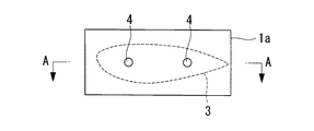
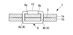
- FIG. 1 is an explanatory diagram of a method for repairing a composite material according to the first embodiment of the present invention.
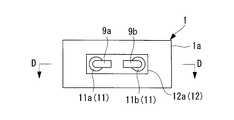
- FIG. 1A shows a top view of a composite material in which a hole is provided in a separation gap generated between the layers of the composite material
- FIG. 1B shows a cross-sectional view of the AA portion shown in FIG. 1A
- FIG. 4 is an explanatory view of a method for repairing a separation gap generated between layers of a composite material.
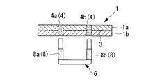
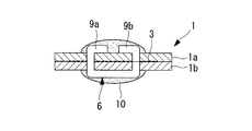
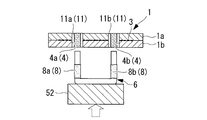
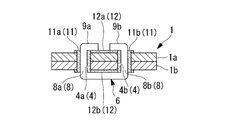
- the composite material 1 is formed by laminating a plurality of (for example, two) composite material layers 1a and 1b. Each layer 1a, 1b of the composite material is completely cured.
- a separation gap 3 is formed between the layer 1a and the layer 1b of the composite material that is completely cured.
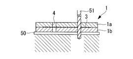
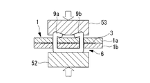
- the method of repairing the peeling gap 3 generated between the composite layers 1a and 1b is such that a hole 4 is passed through the completely hardened composite layers 1a and 1b, and the staples described later are provided in the holes 4. (Coupling member) This is a method of passing through 6 and joining.
- the backing material 50 is installed from below on the composite layers 1a and 1b where the peeling gap 3 is generated.
- the backing material 50 prevents burrs that occur when the holes 4 are provided in the layers 1a and 1b of the composite material.
- the composite material layers 1a and 1b installed on the backing member 50 are provided with holes 4 by a drill 51 having a fine diameter (for example, a diameter of 1.0 mm) from the upper side to the lower side.
- the hole 4 is provided so as to penetrate through a part of the separation gap 3 generated between the layer 1a and the layer 1b of the composite material.
- a plurality of (for example, two) holes 4 are provided in the peeling gap 3 portion.
- the diameters of the holes 4 a and 4 b are the same as the diameter of the drill 51.
- an adhesive is applied to the inside (hole wall) of each hole 4a and 4b.
- an adhesive is also applied to the outside of each needle foot 8a, 8b of the staple needle 6 having two needle feet 8. Note that a filler may be used instead of the adhesive.
- the staple needle 6 has two needle legs 8a and 8b.
- the outer shape of the staple needle 6 has a U shape as shown in FIG. 1C.
- the staple needle 6 is made of a material that has excellent strength characteristics and can be cold worked. For example, a ⁇ titanium material, an Inconel material, or an austenitic stainless material is used.
- the cross-sectional shape perpendicular to the axial direction of each needle foot 8a, 8b of the staple needle 6 is a round shape.
- Each needle foot 8a, 8b has a diameter slightly smaller than that of the hole 4, for example, 0.9 mm.
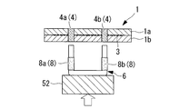
- each needle foot of the staple needle 6 is placed in each hole 4a, 4b. 8a and 8b are inserted from below.
- the staple needle 6 is installed on the upper surface of the needle push-out fitting 52 so that the needle legs 8a and 8b face upward.
- the needle feet 8a and 8b are inserted into the holes 4a and 4b by pushing up the needle push-out fitting 52 on which the staple needle 6 is installed upward from below.
- the end portions 9a and 9b of the needle legs 8a and 8b inserted into the holes 4a and 4b are pushed down from the upper side to the lower side as shown in FIG.
- the metal fitting 52 is bent by being pushed up so as to sandwich the staple needle 6 from below to above.
- the lower surface of the needle bracket 53 is recessed upward in contact with the ends 9a and 9b of the needle legs 8a and 8b. By this depression, the end portions 9a and 9b of the needle legs 8a and 8b are bent so as to face each other.
- each end portion 9a and 9b forms a glasses shape. It is bent as follows. By this bending process, the separation gap 3 generated between the hardened composite material layers 1 a and 1 b can be joined by the staple needle 6.
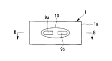
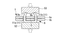
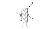
- FIG. 2 shows a sealing process according to the composite material repair method according to the present embodiment
- FIG. 2A is a top view thereof
- FIG. 2B is a cross-sectional view of a BB portion
- FIG. It is the bottom view.
- the staple needle 6 in contact with the surface of the composite material layer 1b and the end portions 9a and 9b of the staple needle 6 in contact with the surface of the composite material layer 1a are sealed so as to cover each other. ) 10 is used for sealing.
- the sealing material 10 covers between the staple needle 6 and the composite layer 1b by covering between the staple needle 6 or each end 9a, 9b of the staple needle 6 and each composite layer 1a, 1b. This ensures water tightness between the end portions 9a and 9b of the staple needle 6 and the composite layer 1a.
- the composite material repairing method and the composite material using the same according to the present embodiment the following effects are obtained.
- the end portions 9a and 9b of the staple needle 6 penetrating the holes 4a and 4b are bent by bending. Therefore, loosening of the staple needle 6 to which the peeling gap 3 is coupled can be prevented. Therefore, the bond of the separation gap 3 generated between the cured composite material layers 1a and 1b can be made firm.
- the sealing material (sealing part) 10 was used for covering. Therefore, it is possible to prevent water from entering between the staple needle 6 and the composite layers 1a and 1b. Therefore, it is possible to easily and inexpensively prevent electrolytic corrosion that occurs when the peeling gap 3 formed between the hardened composite layers 1a and 1b is repaired.
- FIG. 3 shows an explanatory view of the composite material repairing method according to the second embodiment of the present invention.
- FIG. 3A shows a cross-sectional view in which a hole is formed in the separation gap generated between the layers of the composite material
- FIG. 3B shows a cross-sectional view in which a sleeve is inserted into the hole
- FIG. A top view is shown
- FIGS. 3A to 3G are explanatory diagrams of a method for repairing a separation gap generated between layers of a composite material.
- the hole 4 is provided so as to penetrate the separation gap 3 portion by a drill 51 having a diameter slightly larger than that of the first embodiment by, for example, a thickness of a sleeve 11 to be described later. It has been.
- a sleeve 11 is inserted into each hole 4a, 4b provided in each layer 1a, 1b of the composite material.
- the sleeve 11 is a hollow cylinder having an outer diameter of, for example, 1.5 mm and an inner diameter of, for example, 0.9 mm.
- the length of the sleeve 11 is such that it can penetrate the holes 4a and 4b.
- an adhesive is applied to the inside (inner wall) of the sleeves 11 a and 11 b provided in the holes 4 a and 4 b and the outside of the needle feet 8 a and 8 b of the staple needle 6.
- the needle legs 8a and 8b of the staple needle 6 are inserted into the sleeves 11a and 11b to which the adhesive is applied from below.
- the respective sleeves 11a and 11b are inserted into the respective holes 4a and 4b provided in the peeling gap 3, and the respective needle feet 8a of the staple needle (coupling member) 6 are inserted into the respective sleeves 11a and 11b after the respective sleeves 11a and 11b are inserted. 8b is allowed to penetrate.
- the needle feet 8a and 8b of the staple needle 6 are passed through the holes 4a and 4b as they are and then bent, it is possible to prevent the inside of the holes 4a and 4b from being damaged. Accordingly, it is possible to prevent the new peeling from being caused by damage caused in the holes 4a and 4b.
- the sleeves 11a and 11b are inserted into the holes 4a and 4b.
- the present invention is not limited to this, and the sleeves 11a and 11b are inserted into the holes 4a and 4b.
- protective plates may be provided between the staple needle 6 and the composite material layer 1b and between the ends 9a and 9b of the staple needle 6 and the composite material layer 1a.
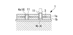
- FIG. 4 shows an explanatory view of a modified example of the composite material repairing method according to the second embodiment of the present invention.
- a protective plate is sandwiched between the composite material layer and the staple needle
- FIG. 4A shows a top view thereof
- FIG. 4B shows a cross-sectional view of a section DD in FIG. 4A. Is shown.
- a protective plate (electrical corrosion resistant material) 12a is sandwiched between the surface of the composite material layer 1a and the end portions 9a and 9b of the staple needle 6.
- a protective plate (electrical corrosion resistant material) 12 b is sandwiched between the surface of the composite material layer 1 b and the staple needle 6.
- the protection plates 12a and 12b are made of an electric corrosion resistant material.
- the protection plates 12a and 12b are provided with holes corresponding to the holes 4a and 4b provided in the composite layers 1a and 1b.
- the protective plates 12a and 12b are provided on the surfaces of the respective layers 1a and 1b of the composite material after the sleeves 11a and 11b are inserted into the holes 4a and 4b. After the protective plates 12a and 12b are provided on the surfaces of the layers 1a and 1b of the composite material, the needle feet 8a and 8b of the staple needle 6 penetrate the protective plates 12a and 12b and further penetrate the holes 4a and 4b. To do.
- Protective plates (electrical corrosion resistant materials) 12 a and 12 b are provided between the cured composite material layers 1 a and 1 b and the staple needle (coupling member) 6. For this reason, it is possible to prevent electrolytic corrosion generated when the staple needle 6 contacts the composite layers 1a and 1b. Therefore, it is possible to prevent the staple needle 6 from deteriorating due to electrolytic corrosion after repairing a peeling gap (not shown) generated between the cured composite layers 1a and 1b.
- FIG. 5 shows an explanatory view of the composite material repairing method according to the third embodiment of the present invention. 5 shows that the ends of the staple needles are caulked by a caulking sleeve, FIG. 5A shows a top view thereof, FIG. 5B shows a cross-sectional view of the EE portion shown in FIG. 5A, FIG. 5C shows a side view thereof.
- the ends 9a and 9b of the staple needle 6 that has been bent are inserted into the caulking sleeve (caulking portion) 13 from opposite sides.
- the caulking sleeve 13 is a hollow metal cylinder having an inner diameter that can penetrate the ends 9 a and 9 b of the staple needle 6. A force is applied to the caulking sleeve 13 into which the end portions 9a and 9b of the staple needle 6 are inserted from the outside.
- the caulking sleeve 13 is deformed so that the cross-sectional shape becomes a quadrangle as shown in FIG. 5C. As a result, the caulking sleeve 13 is crushed and the ends 9 a and 9 b of the staple needle 6 inserted into the caulking sleeve 13 are fixed.
- the end portions 9a and 9b of the staple needle (coupling member) 6 penetrating through the holes 4a and 4b are caulked by a caulking sleeve (caulking portion) 13. Therefore, it is possible to prevent loosening of the staple needle 6 when the peeling gap 3 is joined, compared to the case where the caulking sleeve 13 is not provided. Therefore, the bond of the separation gap 3 generated between the hardened composite material layers 1a and 1b can be made firmer.
- the end portions 9a and 9b of the staple needle 6 penetrating the holes 4a and 4b have been described as being caulked through the caulking sleeve 13, but the present invention is not limited thereto.
- a hook fitting for hooking the ends 9a, 9b of the staple needle 6 may be used.
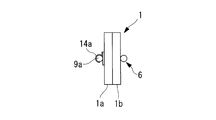
- FIG. 6 shows an explanatory diagram of a first modification of the composite material repairing method according to the third embodiment of the present invention.
- 6 shows that the end of the staple needle is hooked on the hook metal fitting
- FIG. 6A shows the top view thereof
- FIG. 6B shows the cross-sectional view of the FF portion of FIG. 6A
- 6C shows a cross-sectional view taken along a line GG in FIG. 6A
- FIG. 6D shows a cross-sectional view taken along a line HH in FIG. 6A.
- the hook metal (restraint part) 14 is bonded to the surface of the hardened composite material layer 1a.
- the ends 9 a and 9 b of the staple needle (joining member) 6 that has been bent are hooked on the claws 14 a and 14 b of the hook metal fitting 14, respectively.
- the end portions 9a and 9b hooked on the claw portions 14a and 14b are bent to the opposite side with respect to the free ends (described later) of the claw portions 14a and 14b. That is, as shown in FIG. 6A, the end portion 9a penetrating the claw portion 14a is bent upward in the drawing, and the end portion 9b penetrating the claw portion 14b is bent downward in the drawing.
- the hook metal fitting 14 has two claw portions 14a and 14b and a hook metal fitting body 14c.
- the hook metal body 14c has a rectangular shape.
- the hook metal body 14 c is provided in the longitudinal direction of the peeling gap 3.
- the two claw portions 14a and 14b are provided on the upper surface of the hook metal body 14c.
- the claw portions 14a and 14b are provided at right angles to the longitudinal direction of the hook metal body 14c.
- the claw portions 14a and 14b have one end fixed to the hook metal body 14c and the other end being a free end.
- the free ends of the two claw portions 14a and 14b are provided to face in opposite directions.
- FIG. 7 shows an explanatory diagram of a second modified example of the composite material repairing method according to the third embodiment of the present invention.
- FIG. 7 shows that each end of the staple needle that has not been bent is caulked by a caulking sleeve
- FIG. 7A shows a top view thereof
- FIG. 7B shows an II portion of FIG. 7A.
- the end portions 9a and 9b of the staple needle 6 that pass through the holes 4a and 4b are each provided with a caulking sleeve (caulking portion) 15 without being bent.
- Each of the caulking sleeves 15a and 15b is a metal tube.
- Each of the caulking sleeves 15a and 15b is caulked at each end 9a and 9b by applying a force from the outside to be deformed.
- the coupling member has been described as the staple needle 6 having a U-shaped outer shape.
- the coupling member is a linear needle that penetrates the holes 4a and 4b, and both ends of the needle are caulked.
- FIG. 8 shows an explanatory diagram of a third modification of the composite material repairing method according to the third embodiment of the present invention.
- the left figure of FIG. 8 shows that both ends of the needle penetrating the hole are caulked without bending, and the right figure shows that both ends of the needle penetrating the hole are caulked and then bent.
- 8A shows a top view thereof
- FIG. 8B shows a cross-sectional view of the JJ portion shown in FIG. 8A
- FIG. 8C shows a bottom view thereof.
- a straight needle (coupling member) 16 passes through each of the holes 4a and 4b.
- caulking sleeves (caulking portions) 15 are provided at both ends of the needle 16a penetrating the hole 4a.
- caulking sleeves 15 are provided at both ends of the needle 16b penetrating the hole 4b, and each end of the needle 16b penetrating the caulking sleeve 15 is bent. Has been processed.
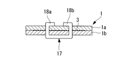
- FIG. 9 shows an explanatory diagram of a composite repair method according to the fourth embodiment of the present invention.
- FIG. 9 shows that the connecting members are connected by staple needles having a needle foot having a square cross-sectional shape
- FIG. 9A shows a top view thereof
- FIG. 9B shows a KK shown in FIG. 9A. Sectional drawing of the part is shown.
- the needle legs 18a and 18b of the staple needle 17 have a rectangular cross section perpendicular to the axial direction.
- the separation gap 3 is joined by using staple needles (joining members) 17 having needle legs 18a and 18b having a square cross section perpendicular to the axial direction. Therefore, the strength for bonding the separation gap 3 can be increased. Therefore, the bond of the separation gap 3 generated between the hardened composite material layers 1a and 1b can be made firmer.
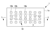
- FIG. 10 is an explanatory diagram of a composite repair method according to the fifth embodiment of the present invention.
- the cross-sectional shape of the needle foot is a quadrangle shape, and the needle foot is connected using a staple needle of a multi-needle foot
- FIG. 10A shows its top view
- FIG. 10A shows a cross-sectional view of the LL portion of FIG. 10A
- FIG. 10C shows a bottom view thereof
- FIG. 10D shows a side view thereof.
- Each staple 19 is provided such that its longitudinal direction is the same as the longitudinal direction of the peeling gap 3.
- the two staple needles 19 are provided so as to be parallel to each other.
- the staple needle 19 has a staple needle body 19a and a plurality of needle legs 19b (for example, 14 needles).
- the staple needle main body 19a has a rectangular shape that can cover the longitudinal direction of the peeling gap 3.
- needle legs 19b are provided in two stages at equal intervals in the longitudinal direction.
- the number of needle feet 19b provided at each stage of the staple needle body 19a is, for example, seven.
- Each needle foot 19b has a quadrangular cross section perpendicular to the axial direction.
- the separation gap 3 was joined using a staple needle (joining member) 19 having 14 (plural) needle legs 19b. Therefore, the bond of the separation gap 3 generated between the hardened composite material layers 1a and 1b can be made firmer.
- the staple needle main body 19a is strengthened, the redundancy can be improved as compared with the case where the staple needles 19 are scattered. Further, when a dedicated needle push-out fitting (not shown) and a needle receiving fitting (not shown) are produced for the staple needle 19, the staple needle 19 can be attached only once, so that the work time can be reduced. Shortening can be achieved.
- the staple needle body 19a may be hollowed out. Thereby, the weight reduction of the staple needle 19 can be achieved.
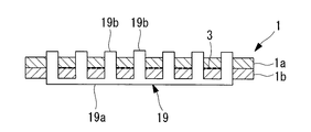
- FIG. 11 shows an explanatory diagram of a composite repair method according to the sixth embodiment of the present invention.
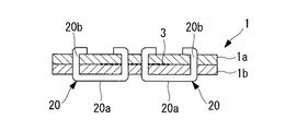
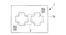
- FIG. 11 shows that the cross-sectional shape of the four needle feet is a quadrangular shape, and that each needle foot is coupled using a staple needle provided on each side of the staple needle body, 11A shows a top view thereof, FIG. 11B shows a cross-sectional view taken along line MM of FIG. 11A, and FIG. 11C shows a bottom view thereof.
- two staple needles (coupling members) 20 are provided.
- the staple needles 20 are provided adjacent to each other.
- the staple needle 20 is sized to cover the peeling gap 3 by providing two staple needles 20 adjacent to each other.
- the staple needle 20 has a staple needle body 20a and four needle legs 20b. As shown in FIG. 11C, the staple needle main body 20a has a square shape when viewed from the lower surface. A needle foot 20b is provided on each side of the staple needle body 20a. Each needle foot 20b has a rectangular (quadrangle) cross-sectional shape perpendicular to the axial direction. Each needle foot 20b is connected to the separation gap 3 by being bent so as to face each other.
- the staple needle 20 provided with four needle feet 20b having a rectangular cross section perpendicular to the axial direction on each side of the staple needle body 20a is used as a coupling member. Therefore, the coupling of the separation gap 3 generated between the hardened composite layers 1a and 1b is simultaneously restrained by the two orthogonal needle feet 20b, thereby making it more firm.
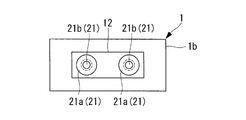
- FIG. 12 shows an explanatory diagram of a composite repair method according to the seventh embodiment of the present invention.
- the right figure of FIG. 12 shows the blind rivet inserted into the hole
- the left figure of FIG. 12 shows the coupling by the blind rivet
- FIG. 12A is its top view
- FIG. 12B is the NN of FIG.
- FIG. 12C shows a bottom view thereof.
- a protective member (electrically resistant material) 12 is provided on the surface of the composite layer 1b.
- a riveter (not shown)
- a blind rivet (coupling member) 21 is passed through the holes 4a and 4b with the protective member 12 interposed therebetween.
- a flanged sleeve 21a of a blind rivet 21 described later is deformed, and the mandrel portion 21b is cut halfway. As a result, the separation gap 3 generated between the cured composite layers 1 a and 1 b is joined by the blind rivet 21.
- the blind rivet 21 includes a flanged sleeve portion 21a and a mandrel portion 21b penetrating through the flanged sleeve portion 21a. As shown in the right view of FIG. 12B, the blind rivet 21 passes through the hole 4b so that the collar portion of the sleeve portion 21a with collar is in contact with the protective member 12 by the riveter.
- the blind rivet 21 penetrating the holes 4a and 4b is operated by pulling the mandrel portion 21b by operating the riveter, so that the sleeved sleeve portion 21a on the surface of the composite material layer 1a is shown in the left figure of FIG. 12B.
- the tip is deformed.
- the flanged sleeve portion 21a is deformed and fixed to the surface of the composite material layer 1a, and then the mandrel portion 21b is adjacent to the flange portion of the flanged sleeve 21a (near the surface of the composite material layer 1b). It is cut at. Thereby, the caulking work by the blind rivet 21 is completed.
- the blind rivet 21 is used as the coupling member. Thereby, the blind rivet 21 can be penetrated into the holes 4a and 4b and caulked. Therefore, the separation gap 3 can be easily coupled as compared with the case where a staple needle (not shown) is used. Therefore, the repair time of the peeling gap 3 generated between the cured composite material layers 1a and 1b can be shortened.
- FIG. 13 shows an explanatory diagram of a composite repair method according to an eighth embodiment of the present invention.
- 13 shows a staple needle whose surface is covered with a covering material
- FIG. 13A shows a longitudinal sectional view thereof
- FIG. 13B shows a transverse sectional view of a needle foot of the staple needle.
- the staple needle (joining member) 22 has a core portion 22a made of a material capable of cold working having excellent strength characteristics, and a covering material (surface coating) 22b coated on the surface of the core portion 22a. ing. The surface of the core portion 22a is covered with a coating material 22b for preventing electrolytic corrosion.
- the staple needle (binding member) 22 provided with a coating material (surface coating) 22b for preventing electrolytic corrosion was used. Therefore, the occurrence of electrolytic corrosion can be prevented without providing a sleeve (not shown). Therefore, it is possible to shorten the repair time of the peeling gap (not shown) generated between the cured composite material layers (not shown), and to prevent the staple needle 22 from being deteriorated due to electrolytic corrosion after the repair. it can.
- the sleeve is not provided, the diameter of the hole (not shown) provided in the composite material (not shown) can be reduced. Therefore, the hole processing is simple, and at the same time, the influence of the strength reduction due to the fiber breakage of the composite material can be suppressed to a small level.
- the covering material 22b has been described as covering what can prevent electrolytic corrosion.
- the present invention is not limited to this, and the covering material 22b is capable of conducting or insulating treatment. There may be.
- FIG. 14 shows an explanatory diagram of a composite repair method according to the ninth embodiment of the present invention.
- FIG. 14 shows a staple needle manufactured using a shape memory alloy
- FIG. 14A shows a state of the staple needle when the temperature is lower than a predetermined temperature
- FIG. 14B shows a state of the staple needle when the temperature is higher than the predetermined temperature. Show.
- the staple needle (coupling member) 23 is manufactured from a shape memory alloy.
- a shape memory alloy for example, a Ti—Ni system is used.
- both ends 23a and 23b of the staple needle 23 extend linearly upward as shown in FIG. 14A.
- the staple needle 23 is heat-treated so that both end portions 23a and 23b bend each other as shown in FIG. 14B.
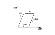
- FIG. 15 shows a load-elongation diagram of the shape memory alloy.
- the horizontal axis indicates the elongation
- the vertical axis indicates the load.
- FIG. 16 shows a schematic diagram of the atoms of the shape memory alloy
- FIG. 16 (A) shows a state at a low temperature
- FIG. 16 (B) shows a state at a high temperature.
- each atom forming the staple needle 23 is stored in a state as shown in FIG. Return. Therefore, the end portions 23a and 23b of the staple needle 23 are bent.
- a shape memory alloy is used as the material of the staple needle (coupling member) 23. Therefore, the staple needle 23 can be formed in a predetermined shape according to the temperature change. Accordingly, by inserting the staple needle 23 into the hole (not shown) and bringing the staple needle 23 to a predetermined temperature, it is easy to repair and repair the peeling gap (not shown) generated between the cured composite layers (not shown). Can be done in a short time.
- FIG. 17 shows an explanatory view of the composite repairing method according to the tenth embodiment of the present invention. 17 shows pressing the ends of the staples of the composite fiber, FIG. 17A shows the top view, FIG. 17B shows the side view, and FIG. 17C shows the X- FIG. 17D shows that the end portions of the staple needle shown in FIG. 17C are joined to each other.
- the staple needle (binding member) 24 is manufactured from a composite fiber impregnated with a resin, for example, a thermoplastic resin.
- a resin for example, a thermoplastic resin.
- the end portions 24a and 24b of the staple needle 24 penetrating the holes 4a and 4b are pressed from above as shown in FIG. 17C. Thereafter, by cooling, the end portions 24a and 24b of the staple needle 24 are accelerated to be cured, and are completely cured and joined as shown in FIG. 17D.
- the composite material repairing method and the composite material using the same according to the present embodiment the following effects are obtained.
- the staple needle (binding member) 24 a composite fiber impregnated with a thermoplastic resin was used. Therefore, the composite fiber impregnated with the thermoplastic resin can be cured and bonded at room temperature. Therefore, the bond of the separation gap 3 generated between the hardened composite material layers 1a and 1b can be made firmer. Further, it is possible to prevent the composite material and the coupling member from being deteriorated by electrolytic corrosion as in the case of using a metal staple needle.
- the staple needle 24 is described as being made of a composite fiber impregnated with a thermoplastic resin, but the present invention is not limited to this, and the fiber impregnated with a thermosetting resin. It may be a reinforced composite material. However, in the case of a thermosetting resin, it is cured by heating to a high temperature.
- the end portions 24a and 24b of the staple needle 24 are described as being pressed and cooled to be joined, but the present invention is not limited to this, and for example, the end portions 24a and 24b.
- the end portions 24a and 24b and the composite material layer 1a may be cured and bonded at a time by being applied to the surface of the composite material layer 1a and cooled by pressing.
- the bonding can be made firmer by the amount fixed to the surface of the layer 1a.
- the cured end portions 24a and 24b may be attached to the surface of the composite material layer 1a with an adhesive.
- an adhesion process is added, but the coupling is firmer than in the case where the end portions 24a and 24b are merely bent and joined.
Landscapes
- Engineering & Computer Science (AREA)
- Mechanical Engineering (AREA)
- Manufacturing & Machinery (AREA)
- Transportation (AREA)
- Aviation & Aerospace Engineering (AREA)
- Lining Or Joining Of Plastics Or The Like (AREA)
- Connection Of Plates (AREA)
Priority Applications (4)
| Application Number | Priority Date | Filing Date | Title |
|---|---|---|---|
| CA2785859A CA2785859C (en) | 2010-02-26 | 2011-02-25 | Repairing method for composite material and composite material using the same |
| US13/519,388 US9993983B2 (en) | 2010-02-26 | 2011-02-25 | Repairing method for composite material and composite material using the same |
| EP11747496.5A EP2540485B1 (de) | 2010-02-26 | 2011-02-25 | Reparaturverfahren für verbundmaterial |
| JP2012501877A JPWO2011105540A1 (ja) | 2010-02-26 | 2011-02-25 | 複合材の修理方法およびこれを用いた複合材 |
Applications Claiming Priority (2)
| Application Number | Priority Date | Filing Date | Title |
|---|---|---|---|
| JP2010043542 | 2010-02-26 | ||
| JP2010-043542 | 2010-02-26 |
Publications (1)
| Publication Number | Publication Date |
|---|---|
| WO2011105540A1 true WO2011105540A1 (ja) | 2011-09-01 |
Family
ID=44506937
Family Applications (1)
| Application Number | Title | Priority Date | Filing Date |
|---|---|---|---|
| PCT/JP2011/054257 WO2011105540A1 (ja) | 2010-02-26 | 2011-02-25 | 複合材の修理方法およびこれを用いた複合材 |
Country Status (5)
| Country | Link |
|---|---|
| US (1) | US9993983B2 (de) |
| EP (1) | EP2540485B1 (de) |
| JP (1) | JPWO2011105540A1 (de) |
| CA (1) | CA2785859C (de) |
| WO (1) | WO2011105540A1 (de) |
Cited By (2)
| Publication number | Priority date | Publication date | Assignee | Title |
|---|---|---|---|---|
| JP2016022738A (ja) * | 2014-07-18 | 2016-02-08 | ザ・ボーイング・カンパニーTheBoeing Company | 積層構造を接合する装置および方法 |
| KR101947582B1 (ko) * | 2017-03-17 | 2019-02-14 | 경상대학교산학협력단 | 복합재 층간분리 수리용 마이크로 체결재 및 이를 채용한 복합재 수리 방법 |
Families Citing this family (10)
| Publication number | Priority date | Publication date | Assignee | Title |
|---|---|---|---|---|
| JPWO2011105540A1 (ja) * | 2010-02-26 | 2013-06-20 | 三菱重工業株式会社 | 複合材の修理方法およびこれを用いた複合材 |
| US8998061B2 (en) | 2010-10-01 | 2015-04-07 | Covidien Lp | Surgical fastener applying apparatus |
| FR2998210B1 (fr) * | 2012-11-20 | 2017-03-10 | Plastic Omnium Cie | Ensemble d'un insert metallique et d'une nappe de materiau composite, procede d'incorporation d'un tel insert dans une telle nappe et piece obtenue par moulage d'une telle nappe |
| US9289207B2 (en) * | 2012-11-29 | 2016-03-22 | Ethicon Endo-Surgery, Llc | Surgical staple with integral pledget for tip deflection |
| GB2550393A (en) * | 2016-05-19 | 2017-11-22 | Rolls Royce Plc | A composite component |
| US10737986B2 (en) | 2017-09-19 | 2020-08-11 | General Electric Company | Methods for repairing composite cylinders |
| US10671047B2 (en) * | 2018-03-15 | 2020-06-02 | The Boeing Company | Composite structure repair system and method |
| CN110442982B (zh) * | 2019-08-09 | 2021-10-12 | 南京工业大学 | 一种复合材料用单边抽钉铆钉结构及其设计方法 |
| WO2021141946A1 (en) * | 2020-01-09 | 2021-07-15 | Bolder Surgical, Llc | A surgical stapler and components and methods therefor |
| CN113478849A (zh) * | 2021-05-14 | 2021-10-08 | 嘉兴市创辉电气工程有限公司 | 一种用于电缆管道的管套和套钉连接装置 |
Citations (9)
| Publication number | Priority date | Publication date | Assignee | Title |
|---|---|---|---|---|
| JPH0274325A (ja) | 1988-09-12 | 1990-03-14 | Mitsubishi Heavy Ind Ltd | 積層型複合材料の製造方法 |
| JPH03286841A (ja) | 1990-04-02 | 1991-12-17 | Mitsubishi Heavy Ind Ltd | 複合材構造物の製造方法 |
| JPH03297629A (ja) | 1990-04-18 | 1991-12-27 | Mitsubishi Heavy Ind Ltd | 熱可塑複合材構造物の製造方法 |
| JPH05501994A (ja) * | 1989-12-07 | 1993-04-15 | シヨート・ブラザース・ピーエルシー | 複合材料 |
| JPH07137154A (ja) | 1993-11-12 | 1995-05-30 | Mitsubishi Heavy Ind Ltd | 樹脂注入修理法 |
| JP2541620B2 (ja) | 1988-04-11 | 1996-10-09 | 富士重工業株式会社 | 複合材構造物の修理方法 |
| JP2002001832A (ja) * | 2001-05-07 | 2002-01-08 | Kawasaki Heavy Ind Ltd | サンドイッチ構造の修理方法 |
| JP2006187897A (ja) * | 2005-01-04 | 2006-07-20 | Fuji Heavy Ind Ltd | 複合材の欠損部修理方法 |
| JP2009208351A (ja) * | 2008-03-04 | 2009-09-17 | Toyota Motor Corp | 複合材料の修復方法、及び複合材料の製造方法 |
Family Cites Families (84)
| Publication number | Priority date | Publication date | Assignee | Title |
|---|---|---|---|---|
| US3215243A (en) * | 1963-04-26 | 1965-11-02 | Edward C Dickerson | Method of repairing roofing material |
| GB1121708A (en) * | 1965-11-18 | 1968-07-31 | Selectus Ltd | Improvements in or relating to fastener members |
| US3365097A (en) * | 1966-02-25 | 1968-01-23 | Dow Chemical Co | Repair patch for lined vessels |
| GB1411379A (en) * | 1971-12-21 | 1975-10-22 | Rolls Royce | Fibre reinforced composite structures |
| JPS55138491A (en) * | 1979-04-13 | 1980-10-29 | Hirose Norizou | Suturing method which use resin needle functioning as thread |
| US4556439A (en) * | 1981-09-25 | 1985-12-03 | The Boeing Company | Method of sealing and bonding laminated epoxy plates |
| US5034254A (en) * | 1984-10-29 | 1991-07-23 | The Boeing Company | Blind-side panel repair patch |
| US4755904A (en) * | 1986-06-06 | 1988-07-05 | The Boeing Company | Lightning protection system for conductive composite material structure |
| US4916880A (en) * | 1986-07-21 | 1990-04-17 | The Boeing Company | Apparatus for repairing a hole in a structural wall of composite material |
| US4978404A (en) * | 1986-07-21 | 1990-12-18 | The Boeing Company | Method for repairing a hole in a structural wall of composite material |
| US4858853A (en) * | 1988-02-17 | 1989-08-22 | The Boeing Company | Bolted repair for curved surfaces |
| DE3909560A1 (de) * | 1989-03-23 | 1990-09-27 | Dornier Luftfahrt | Reparatur von verbundwerkstoffen |
| US5023987A (en) * | 1989-08-28 | 1991-06-18 | The Boeing Company | Strato streak flush patch |
| ES2082036T3 (es) * | 1990-08-20 | 1996-03-16 | Michael D Stewart | Aparato y procedimiento para efectuar reparaciones de estructuras de aviones dañadas no sometidas a esfuerzos. |
| CA2055985A1 (en) * | 1990-12-20 | 1992-06-21 | Daniel Shichman | Fascia clip |
| US5190611A (en) | 1991-02-13 | 1993-03-02 | The Boeing Company | Bearing load restoration method for composite structures |
| US5466087A (en) * | 1992-03-02 | 1995-11-14 | Doole; Kevin G. | Timber connectors |
| US5851645A (en) * | 1995-06-07 | 1998-12-22 | Mcdonnell Douglas Corporation | Composite structure having an externally accessible electrical device embedded therein and a related fabrication method |
| US5893534A (en) * | 1995-12-22 | 1999-04-13 | The Boeing Company | Structural apparatus and design to prevent oil can movement of webs in aircraft pressure bulkheads |
| US5868886A (en) * | 1995-12-22 | 1999-02-09 | Alston; Mark S. | Z-pin reinforced bonded composite repairs |
| GB9622780D0 (en) * | 1996-11-01 | 1997-01-08 | British Aerospace | Repair of composite laminates |
| JPH10243912A (ja) | 1997-03-07 | 1998-09-14 | Duskin Co Ltd | マット等の補修方法 |
| US5948505A (en) * | 1997-03-28 | 1999-09-07 | Andersen Corporation | Thermoplastic resin and fiberglass fabric composite and method |
| WO1998050180A1 (en) * | 1997-05-06 | 1998-11-12 | The Boeing Company | Hybrid lay-up tool |
| US5928448A (en) * | 1997-11-01 | 1999-07-27 | Northrop Grumman Corporation | Dowel adhesive method for repair of ceramic matrix composites |
| AU760808B2 (en) * | 1999-03-23 | 2003-05-22 | Toray Industries, Inc. | Composite reinforcing fiber base material, preform and production method for fiber reinforced plastic |
| JP3243461B2 (ja) * | 1999-07-30 | 2002-01-07 | 川崎重工業株式会社 | サンドイッチ構造 |
| BR0117299B1 (pt) * | 2000-03-03 | 2014-11-25 | Quickstep Technologies Pty Ltd | Métodos para unir componentes compósitos |
| US6497032B2 (en) * | 2000-05-16 | 2002-12-24 | Kimberly-Clark Worldwide, Inc. | Refastenable bonding of garment side panels |
| US20010042501A1 (en) * | 2000-05-17 | 2001-11-22 | Park Ji-Hoon | Temperature sensor using shape memory alloy and manufacturing method thereof |
| US6385836B1 (en) * | 2000-06-30 | 2002-05-14 | Lockheed Martin Corporation | Method for composite material repair |
| DE10125559A1 (de) | 2001-05-23 | 2002-11-28 | Basf Ag | Verbundbauteil und Verfahren zu dessen Herstellung |
| US7008689B2 (en) * | 2001-07-18 | 2006-03-07 | General Electric Company | Pin reinforced, crack resistant fiber reinforced composite article |
| CA2355972C (en) * | 2001-08-24 | 2009-11-17 | Shawcor Ltd. | Ionomer-insulated electrical connectors |
| US20030170441A1 (en) * | 2002-03-05 | 2003-09-11 | Boyle Frederick P. | Composite-structure core |
| US20030190455A1 (en) * | 2002-04-05 | 2003-10-09 | The Boeing Company | Textile joint reinforcement and associated method |
| US7343920B2 (en) * | 2002-12-20 | 2008-03-18 | Toby E Bruce | Connective tissue repair system |
| SE524667C2 (sv) * | 2003-01-30 | 2004-09-14 | Saab Ab | Förfarande för igenfyllning av porer mellan två intillliggande skikt hos ett laminat |
| FR2863324B1 (fr) * | 2003-12-04 | 2007-12-14 | Airbus France | Procede de realisation d'une structure stratifiee et avion muni d'une telle structure |
| US7901461B2 (en) * | 2003-12-05 | 2011-03-08 | Ethicon, Inc. | Viable tissue repair implants and methods of use |
| JP3995253B2 (ja) * | 2004-09-28 | 2007-10-24 | Tdk株式会社 | 感光性ポリイミドパターンの形成方法及び該パターンを有する電子素子 |
| FR2877639B1 (fr) * | 2004-11-10 | 2006-12-15 | Gaz Transp Et Technigaz Soc Pa | Cuve etanche et thermiquement isolee integree a la stucture porteuse d'un navire |
| US7153096B2 (en) * | 2004-12-02 | 2006-12-26 | Siemens Power Generation, Inc. | Stacked laminate CMC turbine vane |
| US8201371B2 (en) * | 2005-03-31 | 2012-06-19 | The Boeing Company | Composite beam chord between reinforcement plates |
| US7721495B2 (en) * | 2005-03-31 | 2010-05-25 | The Boeing Company | Composite structural members and methods for forming the same |
| US9302427B2 (en) * | 2005-03-31 | 2016-04-05 | The Boeing Company | Aeropspace structure including composite beam chord clamped between reinforcement plates |
| US7528598B2 (en) * | 2005-06-22 | 2009-05-05 | Jentek Sensors, Inc. | Fastener and fitting based sensing methods |
| WO2007005657A2 (en) * | 2005-07-01 | 2007-01-11 | Dry Carolyn M | Multiple function, self-repairing composites with special adhesives |
| US7686905B2 (en) | 2005-09-06 | 2010-03-30 | The Boeing Company | Copper grid repair technique for lightning strike protection |
| US7727349B2 (en) * | 2006-04-03 | 2010-06-01 | United Technologies Corporation | Metallic double repair of composite arcuate flanges |
| AU2007231923A1 (en) * | 2006-04-04 | 2007-10-11 | Structural Monitoring Systems Ltd | Method for detecting separation in a structure |
| EP2015889B1 (de) * | 2006-05-11 | 2014-07-09 | Bell Helicopter Textron Inc. | Vorrichtung und verfahren zur reparatur von bauteilen |
| US20100227112A1 (en) * | 2006-10-27 | 2010-09-09 | Nanlin Han | Composite Ply with Adhered Groupings of Fiber Fasteners |
| US20080233346A1 (en) * | 2007-03-23 | 2008-09-25 | United Technologies Corporation | Repair of a composite sandwich structure having a perforated skin |
| FR2915913B1 (fr) * | 2007-05-09 | 2010-02-26 | Airbus France | Procede d'assemblage entre une piece en materiau metallique et une piece en materiau composite au moyen d'une fixation. |
| TWI340400B (en) * | 2007-07-04 | 2011-04-11 | Taiwan Textile Res Inst | Super capacitor structure and method for manufacturing the same |
| US8006605B2 (en) * | 2007-10-10 | 2011-08-30 | Hardware, LLC | Armor panel system |
| US8393068B2 (en) * | 2007-11-06 | 2013-03-12 | The Boeing Company | Method and apparatus for assembling composite structures |
| DE102008021788A1 (de) * | 2008-04-30 | 2009-11-12 | Deutsches Zentrum für Luft- und Raumfahrt e.V. | Verfahren zum Reparieren einer Flugzeugkomponente |
| DE102008039223B8 (de) * | 2008-08-22 | 2010-06-10 | Deutsches Zentrum für Luft- und Raumfahrt e.V. | Faserverbundstruktur und Herstellungsverfahren dafür |
| US8808294B2 (en) * | 2008-09-09 | 2014-08-19 | William Casey Fox | Method and apparatus for a multiple transition temperature implant |
| US20100078259A1 (en) * | 2008-09-30 | 2010-04-01 | Honeywell International Inc. | Flowbodies and methods of forming flowbodies |
| WO2010037991A1 (en) * | 2008-10-03 | 2010-04-08 | Short Brothers Plc | Fibre reinforced composite structures and method of manufacture |
| US8366748B2 (en) * | 2008-12-05 | 2013-02-05 | Kleiner Jeffrey | Apparatus and method of spinal implant and fusion |
| FR2939451B1 (fr) * | 2008-12-09 | 2011-01-07 | Hexcel Reinforcements | Nouveau materiau intermediaire destine a limiter les microfissurations de pieces composites. |
| PL2612973T3 (pl) * | 2009-03-28 | 2017-05-31 | Ewald Dörken Ag | Warstwa funkcyjna powłoki budynku i powłoka budynku z warstwą funkcyjną |
| JPWO2011105540A1 (ja) * | 2010-02-26 | 2013-06-20 | 三菱重工業株式会社 | 複合材の修理方法およびこれを用いた複合材 |
| GB201013227D0 (en) * | 2010-08-06 | 2010-09-22 | Rolls Royce Plc | A composite material and method |
| ES2395604B1 (es) * | 2010-10-29 | 2013-12-26 | Airbus Operations, S.L. | Reparación interior doblada. |
| US20120174292A1 (en) * | 2011-01-10 | 2012-07-12 | Sneyd Syndicate Inc. | Clothing retainer |
| US8091229B2 (en) * | 2011-03-08 | 2012-01-10 | General Electric Company | Method of repairing a subsurface void or damage for a wind turbine blade |
| US8844108B2 (en) * | 2011-07-12 | 2014-09-30 | The Boeing Company | Large area repair of composite aircraft |
| US8454775B2 (en) * | 2011-07-29 | 2013-06-04 | United Technologies Corporation | Bond and stitch repair for delaminated composite |
| US9545774B1 (en) * | 2011-11-07 | 2017-01-17 | The Boeing Company | Reworking ceramic sandwich structures |
| US8601663B2 (en) * | 2012-02-13 | 2013-12-10 | Honeywell International Inc. | Methods for structural repair of components having damaged internally threaded openings and components repaired using such methods |
| US9198662B2 (en) * | 2012-03-28 | 2015-12-01 | Ethicon Endo-Surgery, Inc. | Tissue thickness compensator having improved visibility |
| US8939099B2 (en) * | 2012-06-06 | 2015-01-27 | General Electric Company | Methods and systems for stitching composite materials |
| US20140205800A1 (en) * | 2013-01-23 | 2014-07-24 | Milliken & Company | Externally bonded fiber reinforced polymer strengthening system |
| US9023455B2 (en) * | 2013-01-30 | 2015-05-05 | Ford Global Technologies, Llc | Method of making reinforced composite articles with reduced fiber content in local areas and articles made by the method |
| GB201322275D0 (en) * | 2013-12-17 | 2014-01-29 | Rolls Royce Plc | A Laminated composite structure and related method |
| WO2015105089A1 (ja) * | 2014-01-07 | 2015-07-16 | 株式会社村田製作所 | 補修方法および補修材 |
| US20150224603A1 (en) * | 2014-02-07 | 2015-08-13 | Siemens Energy, Inc. | Filler cloth for laser cladding |
| US9498855B2 (en) * | 2014-04-02 | 2016-11-22 | The Boeing Company | Rework system for composite structures |
| US9657762B2 (en) * | 2015-03-12 | 2017-05-23 | Northrop Grumman Systems Corporation | Thermally activated, shape configurable mechanical locking Z-pin |
-
2011
- 2011-02-25 JP JP2012501877A patent/JPWO2011105540A1/ja active Pending
- 2011-02-25 CA CA2785859A patent/CA2785859C/en not_active Expired - Fee Related
- 2011-02-25 WO PCT/JP2011/054257 patent/WO2011105540A1/ja active Application Filing
- 2011-02-25 EP EP11747496.5A patent/EP2540485B1/de active Active
- 2011-02-25 US US13/519,388 patent/US9993983B2/en not_active Expired - Fee Related
Patent Citations (9)
| Publication number | Priority date | Publication date | Assignee | Title |
|---|---|---|---|---|
| JP2541620B2 (ja) | 1988-04-11 | 1996-10-09 | 富士重工業株式会社 | 複合材構造物の修理方法 |
| JPH0274325A (ja) | 1988-09-12 | 1990-03-14 | Mitsubishi Heavy Ind Ltd | 積層型複合材料の製造方法 |
| JPH05501994A (ja) * | 1989-12-07 | 1993-04-15 | シヨート・ブラザース・ピーエルシー | 複合材料 |
| JPH03286841A (ja) | 1990-04-02 | 1991-12-17 | Mitsubishi Heavy Ind Ltd | 複合材構造物の製造方法 |
| JPH03297629A (ja) | 1990-04-18 | 1991-12-27 | Mitsubishi Heavy Ind Ltd | 熱可塑複合材構造物の製造方法 |
| JPH07137154A (ja) | 1993-11-12 | 1995-05-30 | Mitsubishi Heavy Ind Ltd | 樹脂注入修理法 |
| JP2002001832A (ja) * | 2001-05-07 | 2002-01-08 | Kawasaki Heavy Ind Ltd | サンドイッチ構造の修理方法 |
| JP2006187897A (ja) * | 2005-01-04 | 2006-07-20 | Fuji Heavy Ind Ltd | 複合材の欠損部修理方法 |
| JP2009208351A (ja) * | 2008-03-04 | 2009-09-17 | Toyota Motor Corp | 複合材料の修復方法、及び複合材料の製造方法 |
Non-Patent Citations (1)
| Title |
|---|
| See also references of EP2540485A4 * |
Cited By (2)
| Publication number | Priority date | Publication date | Assignee | Title |
|---|---|---|---|---|
| JP2016022738A (ja) * | 2014-07-18 | 2016-02-08 | ザ・ボーイング・カンパニーTheBoeing Company | 積層構造を接合する装置および方法 |
| KR101947582B1 (ko) * | 2017-03-17 | 2019-02-14 | 경상대학교산학협력단 | 복합재 층간분리 수리용 마이크로 체결재 및 이를 채용한 복합재 수리 방법 |
Also Published As
| Publication number | Publication date |
|---|---|
| US20120301702A1 (en) | 2012-11-29 |
| EP2540485A4 (de) | 2018-01-24 |
| EP2540485A1 (de) | 2013-01-02 |
| US9993983B2 (en) | 2018-06-12 |
| JPWO2011105540A1 (ja) | 2013-06-20 |
| CA2785859C (en) | 2016-10-04 |
| EP2540485B1 (de) | 2020-05-06 |
| CA2785859A1 (en) | 2011-09-01 |
Similar Documents
| Publication | Publication Date | Title |
|---|---|---|
| WO2011105540A1 (ja) | 複合材の修理方法およびこれを用いた複合材 | |
| JP5793216B2 (ja) | 異種材料接合部および異種材料の接合方法 | |
| US8739388B2 (en) | Method of fastening parts to a composite part | |
| US20130149501A1 (en) | Method for connecting a fibre composite component to a structural component of an aircraft and spacecraft and a corresponding arrangement | |
| AU2013336416B2 (en) | Hybrid joint manufacturing | |
| WO2015118931A1 (ja) | 異材パネル構造体 | |
| WO2017110531A1 (ja) | 異材接合構造体 | |
| JP2009144914A5 (de) | ||
| KR101755483B1 (ko) | 이종소재 접합 구조체 | |
| GB2507128A (en) | Hybrid joint manufacturing | |
| JP6341156B2 (ja) | 樹脂接合体、樹脂接合体の製造方法及び車両用構造体 | |
| US20150098755A1 (en) | Structural component | |
| JP2007098439A (ja) | 段付き重合せ材料の摩擦撹拌接合製品 | |
| DE102015210965A1 (de) | Verfahren zur Herstellung eines Bauteilverbundes mit einem Verbindungselement | |
| US9682527B2 (en) | Laminated composite structure and related method | |
| US9186867B2 (en) | Assembly including a reinforced composite part with a pre-formed rivet receiving button | |
| US20140186133A1 (en) | Joint connection between two components, rivet sleeve and blind rivet for such a joint connection and method for producing such a joint connection | |
| JP2017074601A (ja) | 自動車に取り付けられるフレーム構造体を構成する部材同士の接合方法、および自動車に取り付けられるフレーム構造体 | |
| EP2722531A1 (de) | Hybridverbindungsherstellung | |
| DE102016112437B4 (de) | Verfahren zur herstellung eines abschlussteils mittels ultraschallschweissens | |
| JP2013252013A (ja) | 電線の接合構造 | |
| JP2014235777A (ja) | 電線と端子の接合構造及び接合方法 | |
| KR20210022991A (ko) | 이종 소재 접합체 | |
| DE102009004629A1 (de) | Bauteilanordnung und Verfahren zur Herstellung einer Bauteilanordnung | |
| JP2015093482A (ja) | 炭素繊維強化熱可塑性樹脂部材の接合方法 |
Legal Events
| Date | Code | Title | Description |
|---|---|---|---|
| 121 | Ep: the epo has been informed by wipo that ep was designated in this application |
Ref document number: 11747496 Country of ref document: EP Kind code of ref document: A1 |
|
| ENP | Entry into the national phase |
Ref document number: 2785859 Country of ref document: CA |
|
| WWE | Wipo information: entry into national phase |
Ref document number: 13519388 Country of ref document: US Ref document number: 2012501877 Country of ref document: JP |
|
| WWE | Wipo information: entry into national phase |
Ref document number: 2011747496 Country of ref document: EP |
|
| NENP | Non-entry into the national phase |
Ref country code: DE |