US8091229B2 - Method of repairing a subsurface void or damage for a wind turbine blade - Google Patents
Method of repairing a subsurface void or damage for a wind turbine blade Download PDFInfo
- Publication number
- US8091229B2 US8091229B2 US13/042,592 US201113042592A US8091229B2 US 8091229 B2 US8091229 B2 US 8091229B2 US 201113042592 A US201113042592 A US 201113042592A US 8091229 B2 US8091229 B2 US 8091229B2
- Authority
- US
- United States
- Prior art keywords
- defect
- laminate
- boundary
- repair
- procedure
- Prior art date
- Legal status (The legal status is an assumption and is not a legal conclusion. Google has not performed a legal analysis and makes no representation as to the accuracy of the status listed.)
- Active
Links
- 238000000034 method Methods 0.000 title claims abstract description 32
- 239000011800 void material Substances 0.000 title description 10
- 230000007547 defect Effects 0.000 claims abstract description 72
- 230000008439 repair process Effects 0.000 claims abstract description 40
- 239000000463 material Substances 0.000 claims abstract description 28
- 230000009969 flowable effect Effects 0.000 claims abstract description 7
- 238000005553 drilling Methods 0.000 claims abstract description 5
- 238000007689 inspection Methods 0.000 claims description 4
- 230000001066 destructive effect Effects 0.000 claims description 3
- 230000003014 reinforcing effect Effects 0.000 claims 1
- 239000002648 laminated material Substances 0.000 description 6
- 230000032798 delamination Effects 0.000 description 4
- 230000002411 adverse Effects 0.000 description 3
- 230000008901 benefit Effects 0.000 description 3
- 238000012986 modification Methods 0.000 description 3
- 230000004048 modification Effects 0.000 description 3
- 150000001875 compounds Chemical class 0.000 description 2
- 238000011156 evaluation Methods 0.000 description 2
- 238000000227 grinding Methods 0.000 description 2
- 238000003475 lamination Methods 0.000 description 2
- 239000004593 Epoxy Substances 0.000 description 1
- 238000007792 addition Methods 0.000 description 1
- 239000000853 adhesive Substances 0.000 description 1
- 230000001070 adhesive effect Effects 0.000 description 1
- 230000004075 alteration Effects 0.000 description 1
- 230000015572 biosynthetic process Effects 0.000 description 1
- 238000010276 construction Methods 0.000 description 1
- 238000013461 design Methods 0.000 description 1
- 238000010030 laminating Methods 0.000 description 1
- 238000004519 manufacturing process Methods 0.000 description 1
- 230000013011 mating Effects 0.000 description 1
- 238000010422 painting Methods 0.000 description 1
- 230000035515 penetration Effects 0.000 description 1
- 238000010248 power generation Methods 0.000 description 1
- 238000002360 preparation method Methods 0.000 description 1
- 230000008569 process Effects 0.000 description 1
- 230000000717 retained effect Effects 0.000 description 1
- 238000010998 test method Methods 0.000 description 1
- 238000012360 testing method Methods 0.000 description 1
- 238000005382 thermal cycling Methods 0.000 description 1
- XLYOFNOQVPJJNP-UHFFFAOYSA-N water Substances O XLYOFNOQVPJJNP-UHFFFAOYSA-N 0.000 description 1
Images


Classifications
-
- F—MECHANICAL ENGINEERING; LIGHTING; HEATING; WEAPONS; BLASTING
- F03—MACHINES OR ENGINES FOR LIQUIDS; WIND, SPRING, OR WEIGHT MOTORS; PRODUCING MECHANICAL POWER OR A REACTIVE PROPULSIVE THRUST, NOT OTHERWISE PROVIDED FOR
- F03D—WIND MOTORS
- F03D1/00—Wind motors with rotation axis substantially parallel to the air flow entering the rotor
- F03D1/06—Rotors
-
- F—MECHANICAL ENGINEERING; LIGHTING; HEATING; WEAPONS; BLASTING
- F03—MACHINES OR ENGINES FOR LIQUIDS; WIND, SPRING, OR WEIGHT MOTORS; PRODUCING MECHANICAL POWER OR A REACTIVE PROPULSIVE THRUST, NOT OTHERWISE PROVIDED FOR
- F03D—WIND MOTORS
- F03D80/00—Details, components or accessories not provided for in groups F03D1/00 - F03D17/00
- F03D80/50—Maintenance or repair
-
- F—MECHANICAL ENGINEERING; LIGHTING; HEATING; WEAPONS; BLASTING
- F05—INDEXING SCHEMES RELATING TO ENGINES OR PUMPS IN VARIOUS SUBCLASSES OF CLASSES F01-F04
- F05B—INDEXING SCHEME RELATING TO WIND, SPRING, WEIGHT, INERTIA OR LIKE MOTORS, TO MACHINES OR ENGINES FOR LIQUIDS COVERED BY SUBCLASSES F03B, F03D AND F03G
- F05B2260/00—Function
- F05B2260/80—Diagnostics
-
- F—MECHANICAL ENGINEERING; LIGHTING; HEATING; WEAPONS; BLASTING
- F05—INDEXING SCHEMES RELATING TO ENGINES OR PUMPS IN VARIOUS SUBCLASSES OF CLASSES F01-F04
- F05B—INDEXING SCHEME RELATING TO WIND, SPRING, WEIGHT, INERTIA OR LIKE MOTORS, TO MACHINES OR ENGINES FOR LIQUIDS COVERED BY SUBCLASSES F03B, F03D AND F03G
- F05B2280/00—Materials; Properties thereof
- F05B2280/70—Treatments or modification of materials
- F05B2280/702—Reinforcements
-
- F—MECHANICAL ENGINEERING; LIGHTING; HEATING; WEAPONS; BLASTING
- F05—INDEXING SCHEMES RELATING TO ENGINES OR PUMPS IN VARIOUS SUBCLASSES OF CLASSES F01-F04
- F05C—INDEXING SCHEME RELATING TO MATERIALS, MATERIAL PROPERTIES OR MATERIAL CHARACTERISTICS FOR MACHINES, ENGINES OR PUMPS OTHER THAN NON-POSITIVE-DISPLACEMENT MACHINES OR ENGINES
- F05C2253/00—Other material characteristics; Treatment of material
- F05C2253/22—Reinforcements
-
- Y—GENERAL TAGGING OF NEW TECHNOLOGICAL DEVELOPMENTS; GENERAL TAGGING OF CROSS-SECTIONAL TECHNOLOGIES SPANNING OVER SEVERAL SECTIONS OF THE IPC; TECHNICAL SUBJECTS COVERED BY FORMER USPC CROSS-REFERENCE ART COLLECTIONS [XRACs] AND DIGESTS
- Y02—TECHNOLOGIES OR APPLICATIONS FOR MITIGATION OR ADAPTATION AGAINST CLIMATE CHANGE
- Y02E—REDUCTION OF GREENHOUSE GAS [GHG] EMISSIONS, RELATED TO ENERGY GENERATION, TRANSMISSION OR DISTRIBUTION
- Y02E10/00—Energy generation through renewable energy sources
- Y02E10/70—Wind energy
- Y02E10/72—Wind turbines with rotation axis in wind direction
-
- Y—GENERAL TAGGING OF NEW TECHNOLOGICAL DEVELOPMENTS; GENERAL TAGGING OF CROSS-SECTIONAL TECHNOLOGIES SPANNING OVER SEVERAL SECTIONS OF THE IPC; TECHNICAL SUBJECTS COVERED BY FORMER USPC CROSS-REFERENCE ART COLLECTIONS [XRACs] AND DIGESTS
- Y10—TECHNICAL SUBJECTS COVERED BY FORMER USPC
- Y10T—TECHNICAL SUBJECTS COVERED BY FORMER US CLASSIFICATION
- Y10T29/00—Metal working
- Y10T29/49—Method of mechanical manufacture
- Y10T29/49316—Impeller making
- Y10T29/49318—Repairing or disassembling
-
- Y—GENERAL TAGGING OF NEW TECHNOLOGICAL DEVELOPMENTS; GENERAL TAGGING OF CROSS-SECTIONAL TECHNOLOGIES SPANNING OVER SEVERAL SECTIONS OF THE IPC; TECHNICAL SUBJECTS COVERED BY FORMER USPC CROSS-REFERENCE ART COLLECTIONS [XRACs] AND DIGESTS
- Y10—TECHNICAL SUBJECTS COVERED BY FORMER USPC
- Y10T—TECHNICAL SUBJECTS COVERED BY FORMER US CLASSIFICATION
- Y10T29/00—Metal working
- Y10T29/49—Method of mechanical manufacture
- Y10T29/49718—Repairing
- Y10T29/49732—Repairing by attaching repair preform, e.g., remaking, restoring, or patching
- Y10T29/49734—Repairing by attaching repair preform, e.g., remaking, restoring, or patching and removing damaged material
-
- Y—GENERAL TAGGING OF NEW TECHNOLOGICAL DEVELOPMENTS; GENERAL TAGGING OF CROSS-SECTIONAL TECHNOLOGIES SPANNING OVER SEVERAL SECTIONS OF THE IPC; TECHNICAL SUBJECTS COVERED BY FORMER USPC CROSS-REFERENCE ART COLLECTIONS [XRACs] AND DIGESTS
- Y10—TECHNICAL SUBJECTS COVERED BY FORMER USPC
- Y10T—TECHNICAL SUBJECTS COVERED BY FORMER US CLASSIFICATION
- Y10T29/00—Metal working
- Y10T29/49—Method of mechanical manufacture
- Y10T29/49718—Repairing
- Y10T29/49746—Repairing by applying fluent material, e.g., coating, casting
-
- Y—GENERAL TAGGING OF NEW TECHNOLOGICAL DEVELOPMENTS; GENERAL TAGGING OF CROSS-SECTIONAL TECHNOLOGIES SPANNING OVER SEVERAL SECTIONS OF THE IPC; TECHNICAL SUBJECTS COVERED BY FORMER USPC CROSS-REFERENCE ART COLLECTIONS [XRACs] AND DIGESTS
- Y10—TECHNICAL SUBJECTS COVERED BY FORMER USPC
- Y10T—TECHNICAL SUBJECTS COVERED BY FORMER US CLASSIFICATION
- Y10T29/00—Metal working
- Y10T29/49—Method of mechanical manufacture
- Y10T29/4998—Combined manufacture including applying or shaping of fluent material
- Y10T29/49993—Filling of opening
Definitions
- the present invention relates generally to the field of wind turbines, and more particularly to a method for repairing wind turbine blades.
- Turbine blades are the primary elements of wind turbines for converting wind energy into electrical energy.
- the turbine blades typically consist of a suction side shell member and a pressure side shell member that are bonded together at bond lines along the trailing and leading edges of the blade.
- the bond lines are generally formed by applying a suitable bonding paste or compound along the bond line at a minimum designed bond width between the shell members.
- defects occur in the blades from the original manufacturing process or as a result of operational conditions experienced by the blade.
- a void in the original bonding material i.e., from an air bubble or lack of complete fill
- Impact damage from ice, hail, lightning, birds, etc. often results in delamination.
- Thermal cycling e.g., between winter and summer temperatures
- Water penetration through a crack in the external gel coat can also lead to delamination.
- the delamination may exist between the shell members (e.g., within the bonding material) or interlaminate (within the shell member layers).
- the blade defects must be repaired, typically at the site, to ensure efficient operation of the wind turbine at over its design life and power rating.
- the conventional repair procedures for subsurface defects in the blade laminate call for grinding of the effected blade area and subsequent reapplication of the laminate materials. A defect is removed by grinding/sanding the laminate plies until the defect is exposed. The laminate layers are then reapplied and sanded smooth. Typically, an “over-laminate” ply is added to the repair area for additional strength. However, this additional laminate layer extends above the planar surface of the surrounding blade area and thus disrupts airflow over the blade and degrades aerodynamic performance.
- a “drill and fill” technique has been used to repair blade defects in newly manufactured blades (before the blades are deployed in the field). This procedure involves drilling a hole into the defect void and subsequently filling the void with a bonding material. This procedure has not been considered useful for field repairs because of the likelihood of the defect being contaminated with dirt and oxides, resulting in inconsistent repair results. In addition, the structural strength of the repair is not optimal.
- a procedure for repairing subsurface defects in the laminate of a wind turbine blade shell member.
- the procedure includes detecting the location and boundary of the subsurface defect, for example using any manner of suitable non-destructive external inspection technique.
- One or more fill holes are then drilled from an external surface of the laminate into the defect and proximate to a boundary of the defect.
- One or more vent holes are also drilled from the external surface of the laminate into the defect and proximate to an opposite boundary from the fill hole.
- a flowable bonding material is then injected into the fill hole until the bonding material flows from the vent hole.
- the repair zone is then reinforced with at least one mechanical fastener, such as a bolt, rivet, or the like, defined through the laminate either within the boundary of the defect or outboard of the boundary of the defect.
- the repair zone is reinforced with a plurality of the mechanical fasteners.
- the fasteners may be spaced around the periphery of the defect.
- any number of the fasteners may be used within the boundary of the defect. Virtually any pattern and location of the fasteners are contemplated for generating a clamping load on the laminate in and around the defect during curing of the bonding material.
- the mechanical fasteners are not removed from the laminate and are maintained as a permanent component of the repair.
- the mechanical fasteners are countersunk in the external surface of the laminate so as not to generate adverse airflow conditions over the surface of the blade or otherwise adversely affect the aerodynamic performance of the blade.
- the unique repair procedure may be completed on-site with the wind turbine blade remaining on its respective hub and tower.
- the repair procedure may be used at any location on the blade, but is particularly suited for repairing defects along the trailing edge of the wind turbine blade.
- the laminate is defined by the combination of the pressure side shell member, the trailing edge bond line material, and the suction side shell member, and the mechanical fasteners have a length and configuration so as to extend completely through the laminate.
- FIG. 1 is a perspective view of a conventional wind turbine
- FIG. 2 is a perspective view of a wind turbine blade
- FIG. 3 is a view of a section of a trailing edge of a wind turbine blade with laminate layers removed to reveal a subsurface defect
- FIG. 4 is a cross-sectional perspective view of the trailing edge of a wind turbine blade with a fill hole and a vent hole defined therein in accordance with aspects of the repair procedure of the invention
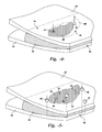
- FIG. 5 is a view of a trailing edge section of FIG. 4 with holes defined therein for receipt of mechanical fasteners;
- FIG. 6 is a cross-sectional view of a trailing edge particularly illustrating receipt of the mechanical fasteners in and around the repair zone;
- FIG. 7 is a cross-sectional view of a repair area where access to the opposite side is not readily available.
- FIG. 1 illustrates a wind turbine 10 of conventional construction.
- the wind turbine 10 includes a tower 12 with a nacelle 14 mounted thereon.
- a plurality of turbine blades 16 are mounted to a rotor hub 18 , which is in turn connected to a main flange that turns a main rotor shaft.
- the wind turbine power generation and control components are housed within the nacelle 14 .
- the view of FIG. 1 is provided for illustrative purposes only to place the present invention in an exemplary field of use. It should be appreciated that the invention is not limited to any particular type of wind turbine configuration.
- FIG. 2 is a more detailed view of a wind turbine blade 16 .
- the blade 16 includes an upper shell member 20 and a lower shell member 22 .
- the upper shell member 20 may be configured as the suction side surface of the blade 16
- the lower shell member 20 may be configured as the pressure side surface of the blade.
- the blade 16 includes a leading edge 24 and a trailing edge 26 , as well as a root portion 28 , and a tip portion 30 .
- the upper shell member 20 , and lower shell member 22 are joined together at a leading edge bond line 32 and a trailing edge bond line 34 .
- a bond paste 36 in flowable viscous form is applied between the mating surfaces of the shell members 20 , 22 along the length of the bond lines 32 , 34 .
- the bond paste 36 is typically applied in a sufficient quantity and pattern so as to establish a designed width of the bond lines 32 , 34 that ensures a minimum bonded surface area between the components.
- bond paste is used herein in a generic sense to encompass any type of adhesive or bonding material that is applied in an initially flowable state, such any suitable type of epoxy, compound, or other material.
- FIG. 2 illustrates multiple subsurface defects 38 formed in the laminate material of either of the shell members 20 , 22 along the trailing edge bond line 34 .
- the depiction of the defects 38 in this region of the blade is presented for illustrative purposes only. It should be appreciated that the present procedure for repairing subsurface defects in a wind turbine blade may be utilized for defects 38 located at any location in the laminate materials of the blade.
- FIG. 3 is an enlarged view of a section of the trailing edge 26 that encompasses one of the defects 38 .
- Layers 42 of the upper shell member 20 have been removed in the illustration in order to depict the subsurface defect 38 having a boundary 40 .
- the defect 38 may be a void in the bond paste 36 , which may extend completely through the laminate to the opposite shell member 22 .
- the defect 38 may be a de-lamination or void in the layers 42 that does not extend to the bond paste 36 , as depicted by the defect 38 in the shell member 20 of FIG. 6 .
- the defect 38 may be a void or de-lamination in the shell member that extends into the bond paste 36 , as depicted by the defect 38 in the shell member 22 of FIG. 6 . It should be appreciated that the present invention is not limited to repair of any particular type of defect in the blade materials.
- the subsurface defects 38 may be detected any known technique.
- the subsurface defect may be detected by inspection for surface defects, such as cracks, waviness, or any other non-destructive evaluation test method.
- the extent or boundary 40 of the defect 38 may be determined by, for example, tap testing, ultrasonic inspection, or any other nondestructive evaluation method.
- a fill hole 44 is drilled into the defect 38 from an external surface of the laminate, as indicated by the arrow in FIG. 4 .
- the hole 44 is drilled proximate to the boundary 40 of the defect, as compared to a more central location.
- a vent hole 46 is also defined from the external surface of the shell member 20 into the defect 38 proximate to the opposite boundary relative to the fill hole 44 . This pattern of the drill hole 44 and vent hole 46 helps to ensure that a flowable bonding material 48 that is injected into the defect 38 through the fill hole 44 completely (or nearly completely) fills the entire void of the defect 38 .
- vent hole 46 By disposing the vent hole 46 generally opposite from the fill hole 44 proximate to the opposite boundary 40 , a more complete fill of the void with the bonding material 48 is achieved.
- fill holes 44 and vent holes 46 may be defined through the external surface of the shell member 20 so as to achieve a complete fill of the defect void, depending on the overall shape, location, and other characteristics of the defect 38 .
- the invention is not limited to any particular number or pattern of fill holes and vent holes.
- the flowable bonding material 48 is injected through the fill hole 44 until the material flows from the vent hole 46 , which is an indication of a complete fill of the defect 38 .
- the holes 44 and 46 may be filled with the bonding material 48 so that, when cured, the material 48 forms a flush surface with the surrounding laminate material with little or no finishing.
- the repair zone is reinforced with any number and configuration of mechanical fasteners 52 that generate a clamping load force on the laminate material in and around the repair zone as the bonding material 48 cures.
- a plurality of fastener holes 50 are defined through the laminate for receipt of the mechanical fasteners 52 ( FIG. 6 ). These holes 50 may be spaced around the periphery of the defect boundary 40 , as well as within the boundary 40 .
- the number and pattern of the holes 50 and mechanical fasteners 52 will vary depending on the size, location, and other characteristics of the defect 38 . In the embodiment depicted in FIGS.
- the holes 50 include countersunk heads 60 defined in the shell members 20 and 22 for receipt of correspondingly shaped heads on the mechanical fasteners 52 .
- the fasteners 52 may be any manner of conventional mechanical fasteners, such as a rivet 58 , or bolt 54 with associated nut 56 .
- the fasteners 52 reside within the countersunk heads 60 and are preferably flush with the surrounding surface of the shell members 20 , 22 so as not to adversely affect the aerodynamic performance of the blade.
- the mechanical fasteners 52 are installed and generate the clamping load on the laminate during the curing of the bonding material 48 , as discussed above. Although there may be certain instances wherein the mechanical fasteners 52 are subsequently removed from the blade and the holes 50 filled with a bonding material and finished, desirably, the mechanical fasteners 52 are not removed from the laminate and are retained as a permanent component of the repair. The fasteners 52 provide an added degree of permanent strength and integrity to the repair zone.
- the defects 38 are adjacent to the trailing edge 36 and, thus, the mechanical fasteners 52 have a length and configuration so as to extend completely through the opposite shell members 20 , 22 .
- the subsurface defects 38 are within the shell member materials at other chord locations, for example at a mid-chord location
- other types of mechanical fasteners may be utilized, such as a through-wall anchor bolt, toggle bolt, or similar device, wherein it is not necessary to have access to the opposite end of the fastener in order to engage and tighten the fastener 52 .
- This configuration is illustrated, for example, in FIG. 7 wherein the mechanical fasteners are toggle bolts 62 used to provide a clamping force within and around the boundary 40 of the subsurface defect 38 .
Landscapes
- Engineering & Computer Science (AREA)
- Life Sciences & Earth Sciences (AREA)
- Sustainable Development (AREA)
- Sustainable Energy (AREA)
- Chemical & Material Sciences (AREA)
- Combustion & Propulsion (AREA)
- Mechanical Engineering (AREA)
- General Engineering & Computer Science (AREA)
- Wind Motors (AREA)
Abstract
Description
Claims (10)
Priority Applications (4)
| Application Number | Priority Date | Filing Date | Title |
|---|---|---|---|
| US13/042,592 US8091229B2 (en) | 2011-03-08 | 2011-03-08 | Method of repairing a subsurface void or damage for a wind turbine blade |
| DKPA201270098A DK178484B1 (en) | 2011-03-08 | 2012-03-06 | Procedure for repairing a wind turbine blade |
| DE102012101880.4A DE102012101880B4 (en) | 2011-03-08 | 2012-03-06 | Method of repairing a wind turbine blade |
| CN2012100736016A CN102705155B (en) | 2011-03-08 | 2012-03-08 | Method for repairing wind turbine blade |
Applications Claiming Priority (1)
| Application Number | Priority Date | Filing Date | Title |
|---|---|---|---|
| US13/042,592 US8091229B2 (en) | 2011-03-08 | 2011-03-08 | Method of repairing a subsurface void or damage for a wind turbine blade |
Publications (2)
| Publication Number | Publication Date |
|---|---|
| US20110209347A1 US20110209347A1 (en) | 2011-09-01 |
| US8091229B2 true US8091229B2 (en) | 2012-01-10 |
Family
ID=44504490
Family Applications (1)
| Application Number | Title | Priority Date | Filing Date |
|---|---|---|---|
| US13/042,592 Active US8091229B2 (en) | 2011-03-08 | 2011-03-08 | Method of repairing a subsurface void or damage for a wind turbine blade |
Country Status (4)
| Country | Link |
|---|---|
| US (1) | US8091229B2 (en) |
| CN (1) | CN102705155B (en) |
| DE (1) | DE102012101880B4 (en) |
| DK (1) | DK178484B1 (en) |
Cited By (9)
| Publication number | Priority date | Publication date | Assignee | Title |
|---|---|---|---|---|
| US20120317808A1 (en) * | 2011-06-17 | 2012-12-20 | General Electric Company | Method and apparatus to repair a turbomachine rotor wheel |
| US20150001982A1 (en) * | 2012-03-23 | 2015-01-01 | Alstom Technology Ltd | Method for repairing a rotor and rotor |
| US9945354B2 (en) | 2014-10-27 | 2018-04-17 | General Electric Company | System and method for controlling bonding material in a wind turbine blade |
| US10041471B1 (en) | 2017-02-09 | 2018-08-07 | Mitsubishi Heavy Industries, Ltd. | Wind turbine blade and reinforcing method for wind turbine blade |
| US20190093637A1 (en) * | 2016-04-20 | 2019-03-28 | Innogy Se | Heavy-duty upgrading method for rotor blades of existing wind turbines |
| US10406639B2 (en) | 2014-05-30 | 2019-09-10 | Ansaldo Energia Switzerland AG | Method for repairing turbine components |
| US10514022B2 (en) | 2017-02-09 | 2019-12-24 | Mitsubishi Heavy Industries, Ltd. | Wind turbine generator system, wind turbine blade, and reinforcing method for wind turbine blade |
| US11235540B2 (en) | 2016-03-25 | 2022-02-01 | Short Brothers Plc | Apparatus and methods for repairing composite laminates |
| US11312507B2 (en) * | 2019-09-03 | 2022-04-26 | The Boeing Company | Repair assembly to repair an area on a member of a vehicle |
Families Citing this family (29)
| Publication number | Priority date | Publication date | Assignee | Title |
|---|---|---|---|---|
| JPWO2011105540A1 (en) * | 2010-02-26 | 2013-06-20 | 三菱重工業株式会社 | Composite repair method and composite material using the same |
| GB201104409D0 (en) * | 2011-03-16 | 2011-04-27 | Airbus Operations Ltd | Improvements in inspection of composite components |
| KR101313571B1 (en) | 2012-06-27 | 2013-10-01 | 삼성중공업 주식회사 | Method for repairing wind turbine blade |
| KR101358127B1 (en) * | 2012-06-27 | 2014-02-07 | 삼성중공업 주식회사 | Drill used for repairing wind turbine blade, and blade repairing system including the same |
| DE102012023617A1 (en) * | 2012-12-04 | 2014-06-05 | Voith Patent Gmbh | Airfoil for a water turbine |
| US20150034266A1 (en) * | 2013-08-01 | 2015-02-05 | Siemens Energy, Inc. | Building and repair of hollow components |
| US9719490B2 (en) * | 2014-10-31 | 2017-08-01 | General Electric Company | Wind turbine blade with bond paste inspection window and associated method |
| GB2537101B (en) * | 2015-03-24 | 2017-04-19 | Vestas Wind Sys As | Repair of wind turbine components |
| EP3298269B1 (en) * | 2015-05-20 | 2020-01-29 | Bladena ApS | A wind turbine blade with a reinforcing member and a method for installing a reinforcing member |
| CN105134505A (en) * | 2015-07-03 | 2015-12-09 | 上海长知实业有限公司 | Glue injection template and method for blade |
| FR3052749B1 (en) * | 2016-06-20 | 2019-07-05 | Airbus Operations (S.A.S.) | RADOME REPAIR METHOD |
| US11292217B2 (en) * | 2018-05-31 | 2022-04-05 | General Electric Company | Composite component void repair |
| CN110962377A (en) * | 2018-09-28 | 2020-04-07 | 成都飞机工业(集团)有限责任公司 | Honeycomb sandwich structure part repairing method capable of reducing structure loss |
| EP4187080B1 (en) * | 2019-03-21 | 2025-09-03 | Siemens Gamesa Renewable Energy A/S | Method of repairing a damaged spar cap of a wind turbine blade of a wind turbine |
| WO2020247795A1 (en) * | 2019-06-07 | 2020-12-10 | Tpi Composites, Inc. | Mold precision pins for component location during fabrication of wind turbine blades |
| EP4208643B1 (en) * | 2020-09-01 | 2024-05-22 | Vestas Wind Systems A/S | Method of repairing a wind turbine |
| EP4019230B1 (en) | 2020-12-17 | 2024-01-03 | The Boeing Company | Apparatus and method for evacuated injection repair of bondline voids and bondline void repaired by said method |
| GB202100935D0 (en) * | 2021-01-25 | 2021-03-10 | Lm Wind Power As | Reinforcement of bushing assembly in a wind turbine blade |
| CN112976617A (en) * | 2021-01-29 | 2021-06-18 | 中材科技(萍乡)风电叶片有限公司 | Drilling maintenance method for wind power blade pultrusion main beam |
| CN112959697B (en) * | 2021-03-29 | 2023-07-25 | 上海艾港风电科技发展有限公司 | Post-defect-adhesive-shortage maintenance method for nondestructive inspection girder of wind power blade |
| CN113787740B (en) * | 2021-09-26 | 2023-09-19 | 沈阳工业大学 | Wind turbine blade trailing edge reinforcement repairing method |
| CN114718802B (en) * | 2022-04-12 | 2024-11-15 | 中国科学院工程热物理研究所 | An improved method for preventing blade buckling of horizontal axis wind turbines in service |
| US12209997B2 (en) * | 2022-04-26 | 2025-01-28 | Rtx Corporation | Inspection systems and methods for sealing surfaces |
| CN114953528A (en) * | 2022-05-12 | 2022-08-30 | 宁波曙翔新材料股份有限公司 | Method for repairing damage to surface of radar stealth foam structure plate anywhere |
| DE102023204709A1 (en) * | 2023-05-19 | 2024-11-21 | Fraunhofer-Gesellschaft zur Förderung der angewandten Forschung eingetragener Verein | Method for preparing a repair of a rotor blade of a wind turbine, support structure, rotor blade system and repair method |
| WO2025019428A1 (en) * | 2023-07-14 | 2025-01-23 | Gulf Wind Technology | Injection repair of composite fatigue cracks |
| ES3039357A1 (en) * | 2024-04-18 | 2025-10-20 | Nordex Energy Spain Sau | Method for repairing a subsurface defect of a wind turbine rotor blade, wind turbine rotor blade and wind turbine (Machine-translation by Google Translate, not legally binding) |
| CN119261255A (en) * | 2024-10-22 | 2025-01-07 | 西北工业大学 | A method for repairing interface defects of resin-based multilayer composite materials |
| CN121316297A (en) * | 2025-12-12 | 2026-01-13 | 中车洛阳机车有限公司 | A method for repairing aging and cracking of the insulating top cover of a high-altitude locomotive |
Citations (31)
| Publication number | Priority date | Publication date | Assignee | Title |
|---|---|---|---|---|
| US3211813A (en) * | 1961-12-14 | 1965-10-12 | Herman C Behrendt | Method and device for repairing bowling pins |
| US3365097A (en) * | 1966-02-25 | 1968-01-23 | Dow Chemical Co | Repair patch for lined vessels |
| US4311656A (en) * | 1980-08-21 | 1982-01-19 | Spriggs William A | Method for repairing extensive damage to plasterboard wall areas |
| US4334798A (en) * | 1978-11-20 | 1982-06-15 | James Milne | Method of filling a hole in the ground |
| US4354332A (en) * | 1980-04-29 | 1982-10-19 | Lentz Arthur H | Plaster and dry wall hole repair |
| US4517038A (en) * | 1983-05-10 | 1985-05-14 | Miller Robert W | Method of repairing ballistic damage |
| US4855182A (en) * | 1986-10-03 | 1989-08-08 | Isovolta Osterreichische Isolierstoffwerke Aktiengesellschaft | Repair laminate |
| US4858853A (en) * | 1988-02-17 | 1989-08-22 | The Boeing Company | Bolted repair for curved surfaces |
| US4916880A (en) * | 1986-07-21 | 1990-04-17 | The Boeing Company | Apparatus for repairing a hole in a structural wall of composite material |
| US4978404A (en) * | 1986-07-21 | 1990-12-18 | The Boeing Company | Method for repairing a hole in a structural wall of composite material |
| US4993876A (en) * | 1986-06-16 | 1991-02-19 | 501 Sandoz, Ltd. | Method and apparatus for protective encapsulation of structural members |
| US5023987A (en) * | 1989-08-28 | 1991-06-18 | The Boeing Company | Strato streak flush patch |
| US5129135A (en) * | 1990-06-18 | 1992-07-14 | Yoshino Seiki Inc. | Repair method for exterior on a concrete structure |
| US5245812A (en) * | 1992-07-29 | 1993-09-21 | Landers Phillip G | Method of strengthening a structural element |
| US5476340A (en) * | 1994-12-21 | 1995-12-19 | Contrasto; Sam | Method of using internal metal stitching for repairing cracks in concrete |
| US5543091A (en) * | 1994-08-18 | 1996-08-06 | Conley; Jeffery R. | Foam process of restoring depressions in carpet |
| US5809736A (en) * | 1995-04-06 | 1998-09-22 | Hayashi Kensetsu Kogyo Kabushiki Kaisha | Method and apparatus for injecting concrete repairing agent into a concrete structure |
| US5819497A (en) * | 1997-02-20 | 1998-10-13 | Knepper; Richard T. | Method and device for repairing fasteners attached to plaster board |
| US5908285A (en) * | 1995-03-10 | 1999-06-01 | United Technologies Corporation | Electroformed sheath |
| US6054673A (en) * | 1997-09-17 | 2000-04-25 | General Electric Company | Method and apparatus for laser drilling |
| US6385836B1 (en) * | 2000-06-30 | 2002-05-14 | Lockheed Martin Corporation | Method for composite material repair |
| US6656299B1 (en) * | 2001-12-19 | 2003-12-02 | Lockheed Martin Corporation | Method and apparatus for structural repair |
| US6770349B2 (en) * | 1999-07-30 | 2004-08-03 | Kawasaki Jukogyo Kabushiki Kaisha | Sandwich structure and method of repairing the same |
| US7118640B2 (en) * | 2001-12-13 | 2006-10-10 | Saab Ab | Method for reinforcing a double-shell structure |
| US20070113402A1 (en) * | 2005-11-22 | 2007-05-24 | United Technologies Corporation | Methods for repairing gas turbine engine components |
| US7252727B2 (en) * | 2004-06-02 | 2007-08-07 | Deturris Stephan | Repair system and method for fiberglass boats |
| US7360993B2 (en) * | 2002-09-27 | 2008-04-22 | Marine Current Turbines, Ltd. | Fatigue resistant large hollow rotor blade for underwater energy converter |
| US7368073B2 (en) * | 2003-01-30 | 2008-05-06 | Saab | Repair method |
| US7513024B2 (en) * | 2005-08-24 | 2009-04-07 | General Electric Company | Method for repairing structural cracks |
| US7653996B2 (en) * | 2005-09-06 | 2010-02-02 | Siemens Aktiengesellschaft | Method of repairing a crack in a turbine component |
| US7841084B2 (en) * | 2006-03-09 | 2010-11-30 | Mtu Aero Engines Gmbh | Gas turbine components and method for machining gas turbine components |
Family Cites Families (8)
| Publication number | Priority date | Publication date | Assignee | Title |
|---|---|---|---|---|
| US4208456A (en) * | 1979-03-08 | 1980-06-17 | The General Tire & Rubber Company | Repair of FRP parts |
| DE3909560A1 (en) * | 1989-03-23 | 1990-09-27 | Dornier Luftfahrt | Repair of composite materials |
| JP4764011B2 (en) * | 2005-01-04 | 2011-08-31 | 富士重工業株式会社 | Repair method for defective parts of composite materials |
| GB0805713D0 (en) * | 2008-03-28 | 2008-04-30 | Blade Dynamics Ltd | A wind turbine blade |
| CN101865075B (en) * | 2009-04-14 | 2012-01-11 | 上海艾郎风电科技发展有限公司 | Method for shaping front edge of megawatt wind-power blade |
| US7927077B2 (en) * | 2009-07-09 | 2011-04-19 | General Electric Company | Wind blade spar cap laminate repair |
| EP2476033B1 (en) | 2009-09-08 | 2019-06-19 | Fraunhofer-Gesellschaft zur Förderung der angewandten Forschung e.V. | Model-based method for monitoring the condition of rotor blades |
| FR2950079A1 (en) | 2009-09-16 | 2011-03-18 | Aircelle Sa | Device or local heat treatment of a piece, comprises an enclosure equipped with a heating unit, a unit for injecting a fluid on the heated piece, and a sealing unit placed at periphery of the enclosure to produce over pressure in enclosure |
-
2011
- 2011-03-08 US US13/042,592 patent/US8091229B2/en active Active
-
2012
- 2012-03-06 DK DKPA201270098A patent/DK178484B1/en active
- 2012-03-06 DE DE102012101880.4A patent/DE102012101880B4/en active Active
- 2012-03-08 CN CN2012100736016A patent/CN102705155B/en active Active
Patent Citations (32)
| Publication number | Priority date | Publication date | Assignee | Title |
|---|---|---|---|---|
| US3211813A (en) * | 1961-12-14 | 1965-10-12 | Herman C Behrendt | Method and device for repairing bowling pins |
| US3365097A (en) * | 1966-02-25 | 1968-01-23 | Dow Chemical Co | Repair patch for lined vessels |
| US4334798A (en) * | 1978-11-20 | 1982-06-15 | James Milne | Method of filling a hole in the ground |
| US4354332A (en) * | 1980-04-29 | 1982-10-19 | Lentz Arthur H | Plaster and dry wall hole repair |
| US4311656A (en) * | 1980-08-21 | 1982-01-19 | Spriggs William A | Method for repairing extensive damage to plasterboard wall areas |
| US4517038A (en) * | 1983-05-10 | 1985-05-14 | Miller Robert W | Method of repairing ballistic damage |
| US4993876A (en) * | 1986-06-16 | 1991-02-19 | 501 Sandoz, Ltd. | Method and apparatus for protective encapsulation of structural members |
| US4916880A (en) * | 1986-07-21 | 1990-04-17 | The Boeing Company | Apparatus for repairing a hole in a structural wall of composite material |
| US4978404A (en) * | 1986-07-21 | 1990-12-18 | The Boeing Company | Method for repairing a hole in a structural wall of composite material |
| US4855182A (en) * | 1986-10-03 | 1989-08-08 | Isovolta Osterreichische Isolierstoffwerke Aktiengesellschaft | Repair laminate |
| US4858853A (en) * | 1988-02-17 | 1989-08-22 | The Boeing Company | Bolted repair for curved surfaces |
| US5023987A (en) * | 1989-08-28 | 1991-06-18 | The Boeing Company | Strato streak flush patch |
| US5129135A (en) * | 1990-06-18 | 1992-07-14 | Yoshino Seiki Inc. | Repair method for exterior on a concrete structure |
| US5245812A (en) * | 1992-07-29 | 1993-09-21 | Landers Phillip G | Method of strengthening a structural element |
| US5543091A (en) * | 1994-08-18 | 1996-08-06 | Conley; Jeffery R. | Foam process of restoring depressions in carpet |
| US5476340A (en) * | 1994-12-21 | 1995-12-19 | Contrasto; Sam | Method of using internal metal stitching for repairing cracks in concrete |
| US5908285A (en) * | 1995-03-10 | 1999-06-01 | United Technologies Corporation | Electroformed sheath |
| US5809736A (en) * | 1995-04-06 | 1998-09-22 | Hayashi Kensetsu Kogyo Kabushiki Kaisha | Method and apparatus for injecting concrete repairing agent into a concrete structure |
| US5819497A (en) * | 1997-02-20 | 1998-10-13 | Knepper; Richard T. | Method and device for repairing fasteners attached to plaster board |
| US6054673A (en) * | 1997-09-17 | 2000-04-25 | General Electric Company | Method and apparatus for laser drilling |
| US6770349B2 (en) * | 1999-07-30 | 2004-08-03 | Kawasaki Jukogyo Kabushiki Kaisha | Sandwich structure and method of repairing the same |
| US6385836B1 (en) * | 2000-06-30 | 2002-05-14 | Lockheed Martin Corporation | Method for composite material repair |
| US7118640B2 (en) * | 2001-12-13 | 2006-10-10 | Saab Ab | Method for reinforcing a double-shell structure |
| US6656299B1 (en) * | 2001-12-19 | 2003-12-02 | Lockheed Martin Corporation | Method and apparatus for structural repair |
| US7360993B2 (en) * | 2002-09-27 | 2008-04-22 | Marine Current Turbines, Ltd. | Fatigue resistant large hollow rotor blade for underwater energy converter |
| US7368073B2 (en) * | 2003-01-30 | 2008-05-06 | Saab | Repair method |
| US7252727B2 (en) * | 2004-06-02 | 2007-08-07 | Deturris Stephan | Repair system and method for fiberglass boats |
| US7513024B2 (en) * | 2005-08-24 | 2009-04-07 | General Electric Company | Method for repairing structural cracks |
| US7653996B2 (en) * | 2005-09-06 | 2010-02-02 | Siemens Aktiengesellschaft | Method of repairing a crack in a turbine component |
| US20070113402A1 (en) * | 2005-11-22 | 2007-05-24 | United Technologies Corporation | Methods for repairing gas turbine engine components |
| US7761989B2 (en) * | 2005-11-22 | 2010-07-27 | United Technologies Corporation | Methods for repairing gas turbine engine components |
| US7841084B2 (en) * | 2006-03-09 | 2010-11-30 | Mtu Aero Engines Gmbh | Gas turbine components and method for machining gas turbine components |
Cited By (13)
| Publication number | Priority date | Publication date | Assignee | Title |
|---|---|---|---|---|
| US8601689B2 (en) * | 2011-06-17 | 2013-12-10 | General Electric Company | Method and apparatus to repair a turbomachine rotor wheel |
| US20120317808A1 (en) * | 2011-06-17 | 2012-12-20 | General Electric Company | Method and apparatus to repair a turbomachine rotor wheel |
| US20150001982A1 (en) * | 2012-03-23 | 2015-01-01 | Alstom Technology Ltd | Method for repairing a rotor and rotor |
| US10193407B2 (en) * | 2012-03-23 | 2019-01-29 | General Electric Technology Gmbh | Method for repairing a rotor |
| US10406639B2 (en) | 2014-05-30 | 2019-09-10 | Ansaldo Energia Switzerland AG | Method for repairing turbine components |
| US9945354B2 (en) | 2014-10-27 | 2018-04-17 | General Electric Company | System and method for controlling bonding material in a wind turbine blade |
| US11235540B2 (en) | 2016-03-25 | 2022-02-01 | Short Brothers Plc | Apparatus and methods for repairing composite laminates |
| US11999117B2 (en) | 2016-03-25 | 2024-06-04 | Short Brothers Plc | Apparatus and methods for repairing composite laminates |
| US20190093637A1 (en) * | 2016-04-20 | 2019-03-28 | Innogy Se | Heavy-duty upgrading method for rotor blades of existing wind turbines |
| US11118563B2 (en) | 2017-02-09 | 2021-09-14 | Mitsubishi Heavy Industries, Ltd. | Wind turbine generator system, wind turbine blade, and reinforcing method for wind turbine blade |
| US10514022B2 (en) | 2017-02-09 | 2019-12-24 | Mitsubishi Heavy Industries, Ltd. | Wind turbine generator system, wind turbine blade, and reinforcing method for wind turbine blade |
| US10041471B1 (en) | 2017-02-09 | 2018-08-07 | Mitsubishi Heavy Industries, Ltd. | Wind turbine blade and reinforcing method for wind turbine blade |
| US11312507B2 (en) * | 2019-09-03 | 2022-04-26 | The Boeing Company | Repair assembly to repair an area on a member of a vehicle |
Also Published As
| Publication number | Publication date |
|---|---|
| DE102012101880B4 (en) | 2022-02-24 |
| DE102012101880A1 (en) | 2012-09-13 |
| DK201270098A (en) | 2012-09-09 |
| CN102705155B (en) | 2013-10-30 |
| CN102705155A (en) | 2012-10-03 |
| US20110209347A1 (en) | 2011-09-01 |
| DK178484B1 (en) | 2016-04-11 |
Similar Documents
| Publication | Publication Date | Title |
|---|---|---|
| US8091229B2 (en) | Method of repairing a subsurface void or damage for a wind turbine blade | |
| Ataya et al. | Damages of wind turbine blade trailing edge: Forms, location, and root causes | |
| US8297933B2 (en) | Wind turbine blade with modular leading edge | |
| US10578078B2 (en) | Wind turbine rotor blade assembly with root extension panel and method of assembly | |
| CN111108289B (en) | Injection method and apparatus for joining and repairing shear webs | |
| US9500179B2 (en) | Segmented wind turbine blades with truss connection regions, and associated systems and methods | |
| US9745954B2 (en) | Rotor blade joint assembly with multi-component shear web | |
| US20110187115A1 (en) | Highly Reliable, Low Cost Wind Turbine Rotor Blade | |
| US12215667B2 (en) | Longitudinal edge extension | |
| US20160279867A1 (en) | A joining method for wind turbine blade shells | |
| BR112018000856B1 (en) | Method of manufacturing a wind turbine blade | |
| US9702339B2 (en) | Wind turbine blades with cap-assisted bond configuration and associated bonding method | |
| KR20230065250A (en) | Leading edge protection for wind turbine blades | |
| EP3679245A1 (en) | A method for reinforcing a wind turbine blade | |
| WO2019115372A1 (en) | A leading edge device, methods of manufacturing and in-stalling the leading edge device and a wind turbine blade | |
| US20150167473A1 (en) | Modified rotor blade assemblies with access windows and methods for making the same | |
| JP6541742B2 (en) | Wind turbine blade repair method | |
| US11719222B2 (en) | Method of joining wind turbine rotor blade segments via structural members | |
| US20250020108A1 (en) | Injection repair of composite fatigue cracks | |
| US9032622B2 (en) | Methods of manufacturing wind turbine blades | |
| CN114658258B (en) | A device and method for reinforcing cracked wooden beams in wooden structures of ancient buildings | |
| DK202270287A1 (en) | Repair of a wind turbine blade | |
| EP4603697A1 (en) | Method for repairing a wind turbine rotor blade and wind turbine rotor blade | |
| WO2025019428A1 (en) | Injection repair of composite fatigue cracks | |
| CN120792214A (en) | Repair method and repair structure of co-cured metal composite honeycomb sandwich structure |
Legal Events
| Date | Code | Title | Description |
|---|---|---|---|
| AS | Assignment |
Owner name: GENERAL ELECTRIC COMPANY, NEW YORK Free format text: ASSIGNMENT OF ASSIGNORS INTEREST;ASSIGNORS:DEAK, STEPHEN MICHAEL;RIDDELL, SCOTT GABELL;REEL/FRAME:025916/0374 Effective date: 20110303 |
|
| STCF | Information on status: patent grant |
Free format text: PATENTED CASE |
|
| FPAY | Fee payment |
Year of fee payment: 4 |
|
| MAFP | Maintenance fee payment |
Free format text: PAYMENT OF MAINTENANCE FEE, 8TH YEAR, LARGE ENTITY (ORIGINAL EVENT CODE: M1552); ENTITY STATUS OF PATENT OWNER: LARGE ENTITY Year of fee payment: 8 |
|
| MAFP | Maintenance fee payment |
Free format text: PAYMENT OF MAINTENANCE FEE, 12TH YEAR, LARGE ENTITY (ORIGINAL EVENT CODE: M1553); ENTITY STATUS OF PATENT OWNER: LARGE ENTITY Year of fee payment: 12 |
|
| AS | Assignment |
Owner name: LM WIND POWER US TECHNOLOGY APS, DENMARK Free format text: ASSIGNMENT OF ASSIGNORS INTEREST;ASSIGNOR:GENERAL ELECTRIC COMPANY;REEL/FRAME:065531/0160 Effective date: 20231109 |
|
| AS | Assignment |
Owner name: GE INFRASTRUCTURE TECHNOLOGY LLC, SOUTH CAROLINA Free format text: ASSIGNMENT OF ASSIGNORS INTEREST;ASSIGNOR:LM WIND POWER US TECHNOLOGY APS;REEL/FRAME:066869/0770 Effective date: 20240322 |