WO2011105280A1 - 磁気回路及びマグネトロンスパッタ装置 - Google Patents
磁気回路及びマグネトロンスパッタ装置 Download PDFInfo
- Publication number
- WO2011105280A1 WO2011105280A1 PCT/JP2011/053393 JP2011053393W WO2011105280A1 WO 2011105280 A1 WO2011105280 A1 WO 2011105280A1 JP 2011053393 W JP2011053393 W JP 2011053393W WO 2011105280 A1 WO2011105280 A1 WO 2011105280A1
- Authority
- WO
- WIPO (PCT)
- Prior art keywords
- magnetic pole
- magnetic
- target
- magnet
- sputtered
- Prior art date
- Legal status (The legal status is an assumption and is not a legal conclusion. Google has not performed a legal analysis and makes no representation as to the accuracy of the status listed.)
- Ceased
Links
Images




Classifications
-
- C—CHEMISTRY; METALLURGY
- C23—COATING METALLIC MATERIAL; COATING MATERIAL WITH METALLIC MATERIAL; CHEMICAL SURFACE TREATMENT; DIFFUSION TREATMENT OF METALLIC MATERIAL; COATING BY VACUUM EVAPORATION, BY SPUTTERING, BY ION IMPLANTATION OR BY CHEMICAL VAPOUR DEPOSITION, IN GENERAL; INHIBITING CORROSION OF METALLIC MATERIAL OR INCRUSTATION IN GENERAL
- C23C—COATING METALLIC MATERIAL; COATING MATERIAL WITH METALLIC MATERIAL; SURFACE TREATMENT OF METALLIC MATERIAL BY DIFFUSION INTO THE SURFACE, BY CHEMICAL CONVERSION OR SUBSTITUTION; COATING BY VACUUM EVAPORATION, BY SPUTTERING, BY ION IMPLANTATION OR BY CHEMICAL VAPOUR DEPOSITION, IN GENERAL
- C23C14/00—Coating by vacuum evaporation, by sputtering or by ion implantation of the coating forming material
- C23C14/22—Coating by vacuum evaporation, by sputtering or by ion implantation of the coating forming material characterised by the process of coating
- C23C14/34—Sputtering
- C23C14/35—Sputtering by application of a magnetic field, e.g. magnetron sputtering
-
- H—ELECTRICITY
- H01—ELECTRIC ELEMENTS
- H01J—ELECTRIC DISCHARGE TUBES OR DISCHARGE LAMPS
- H01J37/00—Discharge tubes with provision for introducing objects or material to be exposed to the discharge, e.g. for the purpose of examination or processing thereof
- H01J37/32—Gas-filled discharge tubes
- H01J37/34—Gas-filled discharge tubes operating with cathodic sputtering
- H01J37/3402—Gas-filled discharge tubes operating with cathodic sputtering using supplementary magnetic fields
- H01J37/3405—Magnetron sputtering
- H01J37/3408—Planar magnetron sputtering
-
- H—ELECTRICITY
- H01—ELECTRIC ELEMENTS
- H01J—ELECTRIC DISCHARGE TUBES OR DISCHARGE LAMPS
- H01J37/00—Discharge tubes with provision for introducing objects or material to be exposed to the discharge, e.g. for the purpose of examination or processing thereof
- H01J37/32—Gas-filled discharge tubes
- H01J37/34—Gas-filled discharge tubes operating with cathodic sputtering
- H01J37/3411—Constructional aspects of the reactor
- H01J37/345—Magnet arrangements in particular for cathodic sputtering apparatus
- H01J37/3452—Magnet distribution
-
- H—ELECTRICITY
- H01—ELECTRIC ELEMENTS
- H01J—ELECTRIC DISCHARGE TUBES OR DISCHARGE LAMPS
- H01J37/00—Discharge tubes with provision for introducing objects or material to be exposed to the discharge, e.g. for the purpose of examination or processing thereof
- H01J37/32—Gas-filled discharge tubes
- H01J37/34—Gas-filled discharge tubes operating with cathodic sputtering
- H01J37/3411—Constructional aspects of the reactor
- H01J37/345—Magnet arrangements in particular for cathodic sputtering apparatus
- H01J37/3455—Movable magnets
Definitions
- the present invention relates to a magnetic circuit that is provided on the back side of a target and forms a magnetic field on the front side of the target, and a magnetron sputtering apparatus including the magnetic circuit.
- a magnetron sputtering apparatus is known as one of apparatuses for forming a thin film on a semiconductor substrate, a glass substrate or the like.
- a magnetic circuit for forming a leakage magnetic field is arranged in the vicinity of the sputtering target surface of the target on the back side of the target provided in the magnetron sputtering apparatus to increase the density of the plasma formed on the sputtering target surface side of the target. This leakage magnetic field is intended.
- FIGS. 10A and 10B As a magnetic circuit provided in a magnetron sputtering apparatus, for example, a structure shown in FIGS. 10A and 10B is known.
- FIG. 10A shows the planar structure of the target and the magnetic circuit viewed from the back side of the target (the surface side opposite to the surface to be sputtered), and
- FIG. 10B shows the cross-sectional structure of the target and the magnetic circuit. Is shown.
- a disk-shaped inner magnet M ⁇ b> 1 having the same central axis as the target T is disposed on the back side of the disk-shaped target T.
- An outer magnet M2 having an annular shape having the same central axis as the target T is disposed on the back side of the target T so as to be spaced apart from the outer periphery of the inner magnet M1 and surround the inner magnet M1. Yes.
- the inner magnet M1 and the outer magnet M2 constituting the magnetic circuit M are arranged so that their plane sides (surfaces parallel to the target surface) are opposite to each other.
- the magnetron sputtering apparatus When the sputtering process is performed by the magnetron sputtering apparatus described above, first, a direct current or a high frequency voltage is applied to the target T, and an electric field is formed on the surface Ts to be sputtered of the target T. Plasma is generated in the vicinity of the surface Ts. In this state, when a leakage magnetic field is formed by the magnetic circuit M on the surface Ts to be sputtered of the target T, the magnetic field component in the normal direction to the surface to be sputtered Ts of the target T becomes “0” (perpendicular magnetic field). The plasma density is particularly high at the zero point). As a result, the sputtering frequency increases in a region of the surface to be sputtered Ts that faces the vertical magnetic field zero point.
- the progress of erosion in the depth direction of the erosion portion Tg is further accelerated.
- the target T is made of a magnetic material
- a strong magnetic field is generally required. Therefore, the magnetic field formed inside the erosion part Tg is naturally strong, and erosion progresses in the depth direction of the erosion part Tg. Becomes even more prominent.
- a large amount of target T is consumed only in a very small region facing the vertical magnetic field zero line B0.
- the target T has to be replaced inevitably even though there is a sufficient thickness other than the region facing the vertical magnetic field zero line B0.
- the magnetic circuit is decentered from the center of the surface to be sputtered, and the magnetic circuit is rotated with the center of the surface to be sputtered as the center of rotation, so that the region of the erosion portion Tg is covered. Proposals have been made to disperse within the sputtering surface.
- the inner magnet M1 and the outer magnet M2 are reduced in diameter compared with the magnetic circuit M shown in FIG. 10, and the center of the surface Ts to be sputtered.
- the center of the inner magnet M1 and the outer magnet M2 (magnetic circuit center point Cm) is decentered from the target center point Ct by the amount of deviation d in the radial direction of the surface to be sputtered Ts.
- the sputtering process is performed while rotating the magnetic circuit M around the target center point Ct.
- the magnetic circuit center point Cm draws the locus Lc, and the vertical magnetic field zero line is scanned along the circumferential direction of the locus Lc.
- a vertical magnetic field zero region ZB0 which is a region with dots in FIG. 11A, is formed by a large number of vertical magnetic field zero points surrounding the outside of the locus Lc.
- the zero vertical magnetic field region ZB0 expands in the radial direction of the target, and a region where the sputtering frequency is higher than the other regions on the surface Ts to be sputtered expands as the vertical magnetic field zero region ZB0 expands.
- the utilization efficiency of the target T can be improved.
- an earth shield ES connected to the ground potential is disposed around the target as described above as an anode.
- the state of the plasma formed in the vicinity of the surface Ts to be sputtered of the target T, and the film thickness of the thin film formed by sputtering on the surface to be sputtered Ts, is because the potential of the target T is stabilized with respect to this earth shield ES. Maintained.
- the number of magnetic lines of force LM per unit area (magnetic flux density) penetrating the earth shield ES varies as the magnetic circuit M rotates. .
- the magnetic flux density increases in the left part of the earth shield ES shown in FIG.
- the magnetic flux density is lowered in the right part.
- the outer magnet M2 moves to the position indicated by the two-dot chain line in FIG. 12A, the magnetic flux density decreases at the left side portion of the earth shield ES shown in FIG.
- the magnetic flux density is increased at the right side portion of the earth shield ES.
- a voltage that prevents such a change in magnetic flux density is induced in each part of the earth shield ES.
- the potential of the target T with respect to the earth shield ES varies within the surface to be sputtered Ts, and the film thickness varies within the surface of the thin film.
- target potential fluctuations are a more serious problem. It becomes.
- the potential fluctuation of the target T in the surface to be sputtered Ts is not limited to the configuration having the earth shield ES, but generally occurs in a magnetron sputtering apparatus in which another member surrounding the surface to be sputtered Ts functions as an anode. It is. Further, the in-plane variation of the film thickness as described above does not occur only in a magnetic circuit that applies a magnetic field while rotating with respect to a disk-shaped target. Even in the case of a magnetic circuit that applies a magnetic field while moving to the right side or the upper side and the lower side, the magnetic circuit generally occurs in common.
- the present invention has been made in view of the above-described conventional situation, and an object of the present invention is to disperse the erosion portion on the sputtering surface of the target within the sputtering surface while suppressing the in-plane variation of the film thickness.
- a magnetron sputtering apparatus including the magnetic circuit.
- a magnetic circuit that is disposed on the opposite side of the target surface to be sputtered and forms a leakage magnetic field in the vicinity of the surface to be sputtered includes a first magnetic pole part and a second magnetic pole part. And a third magnetic pole portion.
- the second magnetic pole portion is configured to surround the first magnetic pole portion in a direction parallel to the surface to be sputtered, and has a magnetic pole opposite to the first magnetic pole portion and has the magnetic pole to be sputtered. The distribution of the magnetic flux density formed by the second magnetic pole portion on the outside of the surface to be sputtered is maintained via the surface.
- the third magnetic pole part is disposed between the first magnetic pole part and the second magnetic pole part in a direction parallel to the surface to be sputtered, and the first magnetic pole part and the second magnetic pole part.
- the gist is that the distribution of the magnetic flux density formed on the surface to be sputtered by the interaction with the magnetic pole portion can be changed by movement with respect to the surface to be sputtered.
- At least one of the first magnetic pole part and the second magnetic pole part is movable with respect to the surface to be sputtered.
- the gist is that the third magnetic pole portion is provided on at least one of the first magnetic pole portion and the second magnetic pole portion.
- the magnetic circuit of the second aspect includes a first magnet provided as the first magnetic pole part and a second magnet provided as the second magnetic pole part. At least one of the first magnet and the second magnet is provided as a moving body that moves relative to the surface to be sputtered, and the third magnetic pole portion is provided on the moving body. And having a side surface extending in a direction intersecting the moving direction of the moving body.
- a fourth aspect of the present invention is summarized in that, in the magnetic circuit of the third aspect, the third magnetic pole part is a convex part extending in a direction intersecting with a direction in which the moving body moves.
- the target is configured in a disc shape
- the first magnet is configured in a cylindrical shape having the same central axis as the target.
- the second magnet can be rotated around the center of the target, and the second magnet is configured in an annular shape having the same central axis as the target.
- the convex portion is one of a plurality of convex portions provided on the movable body, and each of the plurality of convex portions is provided. Has the same magnetic pole as the moving body provided with the same, and the plurality of convex portions are arranged to be biased in the circumferential direction of the target.
- the seventh aspect of the present invention is a magnetron sputtering apparatus.
- the magnetron sputtering apparatus is disposed on the opposite side of the target from which the surface to be sputtered is exposed, a grounded member disposed around the target, and the target to be sputtered.
- a magnetic circuit that forms a leakage magnetic field in the vicinity of the surface to be sputtered, and the magnetic circuit is composed of the magnetic circuit according to any one of the first to sixth aspects. Is the gist.
- the second magnetic pole portion is disposed so as to surround the first magnetic pole portion of the magnetic circuit.
- the second magnetic pole portion maintains the distribution of the magnetic flux density formed by itself on the surface to be sputtered of the target. Therefore, for example, when the anode is disposed outside the second magnetic pole portion, the distribution of the magnetic flux density penetrating the anode is maintained by the second magnetic pole portion. As a result, the fluctuation of the magnetic flux density at the anode is suppressed, and the potential of the target with respect to the anode becomes stable. As a result, the sputtering speed on the surface to be sputtered is easily maintained uniformly in the surface to be sputtered.
- a third magnetic pole portion is disposed between the first magnetic pole portion and the second magnetic pole portion.
- the position of the vertical magnetic field zero point formed between the first magnetic pole part and the second magnetic pole part is set to the first magnetic pole part or the second magnetic pole part depending on the position of the third magnetic pole part. It can be biased to the part.
- the third magnetic pole portion is movable. Therefore, when the leakage magnetic field is formed by the first magnetic pole part and the second magnetic pole part, the vertical magnetic field zero point generated in the leakage magnetic field is evenly distributed on the surface to be sputtered by the movement of the third magnetic pole part. Can be made.
- the bias of the sputtering reaction on the target surface to be sputtered is evenly distributed on the surface to be sputtered, the erosion portion formed on the surface to be sputtered is evenly distributed on the surface to be sputtered.
- the vertical magnetic field zero point can be dispersed in the surface to be sputtered by moving at least one of the first magnetic pole part and the second magnetic pole part.
- at least one of the first magnet as the first magnetic pole part and the second magnet as the second magnetic pole part moves relative to the surface to be sputtered. It is a moving body, and a third magnetic pole portion is provided on the moving body. Therefore, it is possible to make common the configuration for moving the third magnetic pole portion and the configuration for moving at least one of the first magnetic pole portion and the second magnetic pole portion.
- the third magnetic pole portion has a side surface that intersects the direction in which the moving body moves. According to this configuration, the vertical magnetic field zero line connecting the vertical magnetic field zero points extends in a direction intersecting the moving direction of the moving body.
- a target surface to be sputtered while suppressing in-plane variation in film thickness by a simple configuration in which a convex portion is provided on at least one of the first magnet and the second magnet. It is possible to evenly disperse the erosion part in the direction parallel to the surface to be sputtered.
- the first magnet and the second magnet have the same central axis as the target, and a third magnetic pole portion is provided on at least one of the first magnet and the second magnet. Is provided. According to such a configuration, the vertical magnetic field zero points are easily dispersed in a direction orthogonal to the moving direction of the first magnet. Therefore, it is possible to effectively disperse the region where the vertical magnetic field component is “0” in the direction parallel to the surface to be sputtered.
- the plurality of convex portions are arranged in a biased manner in the circumferential direction of the target.
- a structure of the magnetic circuit in which the plurality of convex portions are arranged with a bias (i) a structure in which convex portions are provided only on the first magnet or the second magnet, or (ii) the first It may be a structure in which convex portions are provided on both of the magnet and the second magnet.
- the vertical magnetic field zero point also approaches the first magnet 12i in the vicinity of the convex portion. Furthermore, it has been found that as the distance away from the convex portion along the circumferential direction of the first magnet increases, the region of the magnetic field having a vertical magnetic field, and thus the vertical magnetic field zero point, approaches the second magnet. .
- the convex portion is provided only on the second magnet in the magnetic circuit of (i) above. That is, the vertical magnetic field zero point approaches the second magnet in the vicinity of the convex portion, but approaches the first magnet as the distance away from the convex portion increases along the circumferential direction of the second magnet. It becomes.
- the vertical magnetic field zero point changes basically as in the case of the magnetic circuit of (i) above. That is, in each of the first and second magnets, the vertical magnetic field zero point is close to the magnet provided with the convex portion in the vicinity of the convex portion, but has a distance away from the convex portion along the circumferential direction of the magnet. The larger it is, the closer to the magnet on which no convex portion is arranged.
- the center of the target and the vertical magnetic field zero line (vertical) are compared with the configuration in which the convex portions are equally arranged in the circumferential direction of the target.
- the difference between the maximum value and the minimum value of the distance to the magnetic field zero point) becomes large. Therefore, the erosion part on the sputtering surface of the target is more dispersed in the sputtering surface.
- FIG. 1 is a top view which shows schematically a part of structure of the magnetron sputtering apparatus which concerns on one embodiment of this invention
- FIG. 2 is sectional drawing of the magnetron sputtering apparatus of Fig.1 (a).
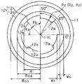
- the figure explaining the external dimension of the magnetic circuit provided in the magnetron sputtering apparatus of FIG. 2 is a graph showing a relationship between a radius vector and a deflection angle at a point where a vertical magnetic field formed by a magnetic circuit provided in the magnetron sputtering apparatus of FIG. 1 is “0”.
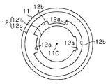
- the top view which shows the structure of the magnetic circuit of a modification with a target.
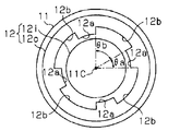
- the top view which shows the structure of the magnetic circuit of a modification with a target.
- the top view which shows the structure of the magnetic circuit of a modification with a target The top view which shows the structure of the magnetic circuit of a modification with a target.
- the top view which shows the structure of the magnetic circuit of a modification with a target The top view which shows the structure of the magnetic circuit of a modification with a target.
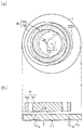
- (A) is a top view which shows the structure of the magnetic circuit of a prior art example with a target
- (b) is sectional drawing which shows the structure of Fig.10 (a).
- (A) is a top view which shows the structure of the magnetic circuit of a prior art example with a target
- (b) is sectional drawing which shows the structure of Fig.11 (a).
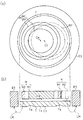
- (A) is a top view which shows the structure of the magnetic circuit of a prior art example with a target
- (b) is sectional drawing which shows the structure of Fig.12 (a).
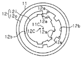
- FIG. 1A is a plan view of the magnetic circuit 12 mounted on the magnetron sputtering apparatus according to the present embodiment and its peripheral structure as viewed from the back side of the target 11, and FIG. It is sectional drawing of (a).
- the back surface of the target 11 refers to a non-sputter surface.
- the magnetron sputtering apparatus includes a vacuum chamber, and a disk-shaped target 11 made of a magnetic material is attached to the cathode of the vacuum chamber.
- the target 11 has a surface as a surface to be sputtered 11s facing the substrate S that is a film formation target.
- a magnetic circuit 12 including an inner magnet 12i as a first magnet and an outer magnet 12o as a second magnet is disposed near the back surface of the target 11.
- the inner magnet 12i and the outer magnet 12o have magnetic poles opposite to each other on the surface 11s to be sputtered of the target 11, and form a leakage magnetic field on the surface 11s to be sputtered.
- the inner magnet 12i of the magnetic circuit 12 has the same central axis as the target 11 and is formed in a gear shape. That is, the center of the inner magnet 12i is positioned coaxially with the target center point 11C, which is the center point of the surface to be sputtered 11s.
- the inner magnet 12i is connected to a rotation shaft 11R that extends in the normal direction of the surface 11s to be sputtered through the target center point 11C. That is, the inner magnet 12i is provided as a moving body that moves relative to the sputtered surface 11s.
- the distribution of the leakage magnetic field per unit area formed by the interaction between the inner magnet 12i and the outer magnet 12o, that is, the distribution of the magnetic flux density is also the rotation axis. It rotates about 11R with respect to the surface 11s to be sputtered.
- the outer magnet 12o of the magnetic circuit 12 has the same central axis as the target 11 and is formed in an annular shape.
- the outer magnet 12o is disposed on the outer peripheral edge of the target 11 so as to surround the inner magnet 12i.
- the outer magnet 12o is connected to a rotating shaft 11R that extends in the normal direction of the surface 11s to be sputtered through the target center point 11C. That is, the outer magnet 12o is also provided as a moving body that moves relative to the sputtered surface 11s, like the inner magnet 12i.
- the inner magnet 12i and the outer magnet 12o are coupled to the rotating shaft 11R while being fixed to a common yoke Y, whereby the inner magnet 12i, the outer magnet 12o, and the yoke Y rotate. It rotates integrally around the shaft 11R.
- the outer magnet 12o forms a leakage magnetic field outside the sputtered surface 11s via the sputtered surface 11s. Even if the inner magnet 12i (that is, the outer magnet 12o) rotates about the rotation axis 11R, the distribution of the leakage magnetic field per unit area formed by the outer magnet 12o on the outer side of the sputtered surface 11s, that is, the magnetic flux density. Distribution is generally maintained.
- each convex portion 12a is arranged on the outer peripheral surface of the inner magnet 12 i so as to follow the circumferential direction of the target 11.
- Each convex portion 12a extends from the center of the inner magnet 12i toward the inner peripheral surface of the outer magnet 12o, that is, radially outward of the inner magnet 12i.
- the inner magnet 12i includes a cylindrical portion as a main body and four convex portions 12a provided on the outer peripheral surface of the cylindrical portion. These convex portions 12a are disposed between the cylindrical portion of the inner magnet 12i and the outer magnet 12o in a direction parallel to the surface to be sputtered 11s.
- the cylindrical portion of the inner magnet 12i is provided as the first magnetic pole portion
- the outer magnet 12o is provided as the second magnetic pole portion
- each convex portion 12a of the inner magnet 12i is provided as the third magnetic pole portion.
- the cylindrical portion of the inner magnet 12i and the four convex portions 12a are integrally formed and have the same magnetic pole.
- a groove portion 12b that is recessed inward in the radial direction is formed between two convex portions 12a adjacent in the circumferential direction of the target 11. That is, four groove portions 12b are formed on the outer peripheral surface of the inner magnet 12i.
- the four convex portions 12a are each configured in a congruent shape, and the four groove portions 12b are also configured in a congruent shape.
- the side surface (protruding surface) farthest from the target center point 11C in the radial direction of the target 11 is a convex curved surface parallel to the inner peripheral surface of the outer magnet 12o.
- the side surface (groove bottom surface) closest to the target center point 11C in the radial direction of the target 11 is also a convex curved surface parallel to the inner peripheral surface of the outer magnet 12o.
- the length of the convex portion 12a in the radial direction of the target 11 is such that the protruding surface of the convex portion 12a and the inner peripheral surface of the outer magnet 12o when the inner magnet 12i rotates around the rotation shaft 11R. Is defined not to touch.
- the length of the projections 12a in the circumferential direction of the target 11 is the same length as the width of the groove portions 12b in the circumferential direction so that the four projections 12a are arranged at equal intervals. It is prescribed.
- the projecting surface of the convex portion 12a is configured such that the central angle (convex portion central angle ⁇ a) is about 45 ° when viewed from a direction parallel to the rotation axis 11R.
- the groove bottom surface of the groove portion 12b is also configured such that the central angle (pitch central angle ⁇ b) is 45 ° when viewed from the direction parallel to the rotating shaft 11R.
- an earth shield 13 as a ground member connected to the ground potential is arranged as an anode.
- the state of the plasma formed in the vicinity of the surface 11s to be sputtered of the target 11 and the film thickness of the thin film formed by the sputtering of the surface 11s to be sputtered are as follows. Maintained.
- a direct current or a high-frequency voltage corresponding to the constituent material of the target 11 is applied to the target 11.
- an electric field is formed on the surface 11s to be sputtered of the target 11, and plasma is generated in the vicinity of the surface 11s to be sputtered.
- the magnetic circuit 12 is rotated with the target center point 11C as the rotation center, and a leakage magnetic field is formed in the vicinity of the sputtered surface 11s by the interaction between the inner magnet 12i and the outer magnet 12o.
- the plasma density is increased at the point where the magnetic field component (vertical magnetic field) in the normal direction to the surface to be sputtered 11s becomes “0” (vertical magnetic field zero point).
- the sputtering frequency increases in the portion of the surface to be sputtered 11s that faces the vertical magnetic field zero point.
- the vertical magnetic field zero point is close to the inner magnet 12i on the outer side in the radial direction of the convex portion 12a, while on the outer side in the radial direction of the groove portion 12b. Close to.
- the shape of the vertical magnetic field zero line 12B0 that is, the spread of the vertical magnetic field zero line 12B0 to the inner magnet 12i and the spread to the outer magnet 12o is determined by the balance of magnetic force between the inner magnet 12i and the outer magnet 12o.
- the vertical magnetic field zero line 12B0 which is a line connecting the vertical magnetic field zero points, is not a circular ring as shown by the two-dot chain line in FIG. 1A, and the distance from the target center point 11C is the diameter of the target 11.
- the non-circular annular vertical magnetic field zero line 12B0 as described above is scanned over the entire circumferential direction of the target 11 around the target center point 11C.
- the vertical magnetic field zero region 12Z which is a region where the component of the vertical magnetic field becomes “0”, is projected in the radial direction of the target 11 (the depth of the groove 12b).
- this vertical magnetic field zero region 12Z is shown as a region with dots.
- the magnetic pole end surface of the inner magnet 12i and the magnetic pole end surface of the outer magnet 12o are both concentric. Become. Therefore, the vertical magnetic field zero line 12B0 formed by these magnets 12i and 12o is also circular with the target center point 11C as the center.
- the vertical magnetic field zero line 12B0 does not spread in a direction crossing the moving direction of the inner magnet 12i. Accordingly, even if the inner magnet 12i rotates, the vertical magnetic field zero region 12Z is not different from the vertical magnetic field zero line 12B0.
- a thin concave portion (erosion portion 11g) corresponding to the vertical magnetic field zero line 12B0 is formed on the sputtered surface 11s of the target 11. Therefore, the target T is consumed only in the region facing the vertical magnetic field zero line 12B0. As a result, the life of the target T is significantly shortened.
- the magnetic circuit 12 since the magnetic circuit 12 has the four convex portions 12a, a non-circular annular vertical magnetic field zero line 12B0 extending in a direction intersecting with the moving direction of the inner magnet 12i. Is formed. Thereby, the vertical magnetic field zero region 12Z is expanded in the radial direction of the sputtered surface 11s. That is, the portion (erosion portion 11g) of the sputtered surface 11s facing the vertical magnetic field zero region 12Z is enlarged by the amount of protrusion of the convex portion 12a. For this reason, the progress of the erosion portion 11g in the sputter surface 11s in the depth direction is delayed, and as a result, the utilization efficiency of the target 11 can be increased.
- the convex portion 12a extends in a direction intersecting with the moving direction of the inner magnet 12i, more specifically, in a tangential direction of the inner peripheral surface of the outer magnet 12o, the vertical magnetic field zero point in the extending direction of the convex portion 12a. Is distributed. Therefore, it is possible to more effectively widen the vertical magnetic field zero region 12Z in which the vertical magnetic field component is “0”.
- the outer magnet 12o that is relatively disposed on the outer edge side of the target 11 rotates around a rotation axis 11R that passes through the target center point 11C. Therefore, when the outer magnet 12o forms the magnetic lines of force LM outside the sputtered surface 11s via the sputtered surface 11s, the magnetic flux per unit area that penetrates the earth shield 13, that is, the magnetic flux density, is the same as that of the inner magnet 12i. It is generally maintained while the magnet 12o rotates together. Therefore, since the fluctuation of the magnetic flux density in the earth shield 13 is suppressed, the potential of the target 11 with respect to the earth shield 13 is stabilized.
- the speed at which the sputtered surface 11s is sputtered is easily maintained uniformly within the sputtered surface 11s.
- the outer center of the outer magnet 12o is made to coincide with the target center point 11C so that when the voltage is applied to the target 11, Even if the magnet 12o is rotated, the fluctuation of the magnetic flux density in the earth shield 13 can be suppressed.
- FIG. 2 is a diagram for explaining the external dimensions of each part of the magnetic circuit 12.
- the outer dimensions of each part in the magnetic circuit 12 and the polar coordinates of the erosion point Pz at which the vertical magnetic field is “0” are defined as follows. -Let the inner diameter of the outer magnet 12o be the outer magnet inner diameter Roa. -Let the outer diameter of the outer magnet 12o be the outer magnet outer shape Rob.
- the minimum distance between the axis of the rotating shaft 11R and the outer peripheral surface of the inner magnet 12i is defined as the inner magnet diameter Ri.
- a difference between the maximum distance between the axis of the rotating shaft 11R and the outer peripheral surface of the inner magnet 12i and the inner magnet diameter Ri is defined as a protrusion amount Wc.
- the difference between the maximum distance between the axis of the rotating shaft 11R and the outer peripheral surface of the inner magnet 12i and the outer magnet inner diameter Roa is defined as a separation amount Ws.
- the distance between the axis of the rotating shaft 11R and the erosion point Pz is defined as a moving radius Rz.
- the angle formed by the half line (the dashed line marked with “0 °” in FIG. 2) with the origin on the axis of the rotating shaft 11R and the half line including the origin and the erosion point Pz is declination. Let ⁇ z.
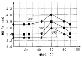
- FIG. 3 is a graph illustrating the relationship between the radius Rz of the erosion point Pz and the deflection angle ⁇ z for each protrusion amount Wc, and the radius Rz and the deflection of the erosion point Pz in the magnetic circuit 12 having the following external dimensions. The relationship with the angle ⁇ z is shown.
- the protrusion amount Wc of the “black circle mark” shown in FIG. 3 is 1.0 cm
- the protrusion amount Wc of the “black square mark” is 0.5 cm
- the radius of the erosion point Pz may be a constant value in the range of the deflection angle ⁇ z of 0 ° to 45 °. I understand. Further, when the declination angle ⁇ z is about 60 °, a peak where the moving radius Rz shows the maximum value is recognized in the range of the declination angle ⁇ z of 45 ° to 90 °.
- the radial width dR1 which is the difference between the maximum value of the radius Rz and the minimum value of the radius Rz is 0.3 centimeter, while the protrusion amount Wc is 0.
- the radial width dR2 is 0.4 cm.
- the radial width dR3 is 0.3 cm.
- the radial widths dR1, dR2, and dR3 correspond to radial widths in the vertical magnetic field zero region 12Z.
- the magnetic circuit 12 having the outer dimensions as described above it can be said that a configuration in which the protruding amount Wc of the convex portion 12a is 0.5 cm is preferable.
- the erosion portion 11g on the surface of the target 11 when the magnetic circuit 12 is used is formed as shown in FIG. The utilization efficiency of the target 11 is improved.
- the effects listed below can be obtained.
- the outer magnet 12 o that is relatively disposed on the outer edge side of the target 11 maintains the distribution of magnetic flux density on the sputtered surface 11 s of the target 11. For this reason, the distribution of the magnetic field penetrating the earth shield 13 disposed around the target 11 is also maintained with respect to the earth shield 13. That is, the fluctuation of the magnetic flux density in the earth shield 13 is suppressed. As a result, the potential of the target 11 with respect to the earth shield 13 is stabilized, and the sputtering speed of the sputtered surface 11s is easily maintained uniformly within the sputtered surface 11s.
- the inner magnet 12i Since the convex portion 12a extending in the direction intersecting the direction in which the inner magnet 12i moves (the circumferential direction of the target 11) is provided on the outer peripheral surface of the inner magnet 12i, the inner magnet 12i is near the convex portion 12a. Is closer to the magnetic pole end surface of the outer magnet 12o. As a result, the vertical magnetic field zero line 12B0 connecting the erosion point Pz is closer to the inner magnet 12i in the vicinity of the convex portion 12a, and closer to the outer magnet 12o as it is farther from the convex portion 12a. Therefore, the vertical magnetic field zero region 12Z spreads in a direction parallel to the surface to be sputtered 11s as compared with the conventional configuration having no convex portion 12a.
- the bias of the sputtering reaction on the surface 11s to be sputtered of the target 11 is dispersed in the surface 11s to be sputtered.
- the erosion portion 11g formed on the surface to be sputtered 11s is dispersed in the surface to be sputtered 11s.
- the position which provides the convex part 12a is not limited to the outer peripheral surface of the inner side magnet 12i.
- a convex portion 12a may be provided on the inner peripheral surface of the outer magnet 12o, for example, as shown in FIG.
- the outer peripheral surface of the inner magnet 12i and the inner periphery of the outer magnet 12o A convex portion 12a may be provided on each surface. That is, if the convex portion 12a is relatively moved by the movement of the magnet, and the distribution of the magnetic flux density formed by the magnet is changed in the surface 11s to be sputtered, the above (1) to (3) are performed. Similar effects can be obtained.
- the convex portions 12a are not limited to being arranged at equal intervals on the outer peripheral surface of the inner magnet 12i.
- the convex portions 12a may be arranged at equal intervals on the inner peripheral surface of the outer magnet 12o.
- two or more convex parts 12a may be arranged in the circumferential direction on the outer circumferential surface of the inner magnet 12i, or may be arranged in the circumferential direction on the inner circumferential surface of the outer magnet 12o.
- a structure of the magnetic circuit in which two or more convex portions 12a are arranged with a bias (i) a structure in which the convex portion 12a is provided only on the inner magnet 12i or the outer magnet 12o, or (ii) an inner magnet It may be a structure in which convex portions 12a are provided on both 12i and the outer magnet 12o.
- the region of the magnetic field having a vertical magnetic field approaches the inner magnet 12i in the vicinity of the convex portion 12a. Therefore, the vertical magnetic field zero point also approaches the inner magnet 12i in the vicinity of the convex portion 12a.
- the region of the magnetic field having a vertical magnetic field approaches the outer magnet 12o.
- the vertical magnetic field zero point changes basically as in the case of the magnetic circuit (i). That is, in each of the inner magnet 12i and the outer magnet 12o, the vertical magnetic field zero point approaches the magnet provided with the convex portion 12a in the vicinity of the convex portion 12a, but is separated from the convex portion 12a along the circumferential direction of the magnet. The larger the distance to be, the closer to the magnet on which the convex portion 12a is not arranged.
- the center of the target 11 and the zero vertical magnetic field are zero as compared with the configuration in which the convex portions 12a are equally arranged in the circumferential direction of the target 11.
- the difference between the maximum value and the minimum value of the distance to the line (vertical magnetic field zero point) increases. Therefore, the erosion part on the sputtered surface 11s of the target 11 is more dispersed in the sputter surface.
- the vertical magnetic field zero line B0 In the vicinity of the convex portion 12a provided on the inner magnet 12i, the vertical magnetic field zero line B0 approaches the inner magnet 12i, and as the distance from the convex portion 12a increases, the vertical magnetic field zero line B0 approaches the outer magnet 12o. It was recognized that However, the locus of the vertical magnetic field zero line B0 is merely an example. That is, the locus of the vertical magnetic field zero line B0 is defined by the balance between the magnetic force of the inner magnet 12i, the magnetic force of the outer magnet 12o, and the protruding amount of the convex portion 12a provided on the inner magnet 12i.
- the vertical magnetic field zero line B0 approaches the outer magnet 12o and the convex portion 12a in the vicinity of the convex portion 12a provided on the inner magnet 12i. It can also be embodied as a configuration in which the farther the distance from is, the closer to the inner magnet 12i.
- the length of the convex portion 12a in the radial direction of the target 11 (the depth of the groove portion 12b) is the inner diameter of the convex curved surface of the convex portion 12a and the outer magnet 12o when the inner magnet 12i rotates around the rotation shaft 11R. It is arbitrarily set as long as it does not contact the peripheral surface. Moreover, the length of the convex part 12a in the radial direction of the target 11 may differ for every convex part 12a. Even with such a configuration, the effects according to the above (1) to (3) can be obtained.
- the length of the convex part 12a in the circumferential direction of the target 11 is not limited to the width of the groove part 12b in the circumferential direction.
- the convex center angle ⁇ a may be smaller than the pitch central angle ⁇ b, or the convex center angle ⁇ a may be larger than the pitch central angle ⁇ b.
- the center point 12c of the inner magnet 12i may be eccentric from the rotation center (target center point 11C) of the inner magnet 12i, for example, as shown in FIG.
- the vertical magnetic field zero region can be further expanded by the amount that the center point 12C of the inner magnet 12i is eccentric from the rotation center of the inner magnet 12i. .
- the convex part 12a as the third magnetic pole part is not limited to being formed integrally with the inner magnet 12i. After the main body (for example, a cylindrical portion) of the inner magnet 12i and the convex portion 12a are separately molded, the main body and the convex portion 12a may be joined. Further, such a configuration can be adopted even when the outer magnet 12o is provided with the convex portion 12a.
- the main body portion (for example, a cylindrical portion) of the inner magnet 12i and the convex portion 12a may have different magnetic poles. Further, such a configuration can be adopted even when the outer magnet 12o is provided with the convex portion 12a.
- the number of the convex portions 12a can be arbitrarily changed as long as the convex portions 12a are separated from each other on the outer peripheral surface of the inner magnet 12i or the inner peripheral surface of the outer magnet 12o.
- the convex part 12a as a 3rd magnetic pole part is not limited to being provided in the inner magnet 12i or the outer magnet 12o.
- the third magnetic pole portion is not provided on any of the inner magnet 12i and the outer magnet 12o, and the target 11 is sputtered between the inner magnet 12i and the outer magnet 12o. You may arrange
- a plurality of rectangular intermediate magnets 12m may be arranged apart from each other on a circle concentric with the target 11.
- eight intermediate magnets 12m are arranged at equal intervals.
- the distance between these intermediate magnets 12m may not be the same.
- the number of intermediate magnets 12m can be arbitrarily changed.
- the intermediate magnet 12m may have the same magnetic pole as the inner magnet 12i, or may have the same magnetic pole as the outer magnet 12o. Further, as the intermediate magnet 12m, a plurality of intermediate magnets 12m having different magnetic poles may be mixed.
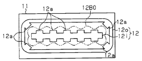
- the target 11 may be a rectangular plate.
- the rectangular annular outer magnet 12o may be positioned with respect to the target 11, and the inner magnet 12i may be configured as a rod that reciprocates along the longitudinal direction of the outer magnet 12o.
- a plurality of convex portions 12a are provided on the inner peripheral surface of the outer magnet 12o, and a plurality of convex portions 12a are also provided on the outer peripheral surface of the inner magnet 12i.
- the shape of the outer magnet 12o is not particularly limited as long as the outer magnet 12o surrounds the moving region of the inner magnet 12i and the distribution of the magnetic flux density from the outer magnet 12o is maintained on the sputtered surface 11s.
- the shape of the inner magnet 12i Is not particularly limited. Even with such a configuration, the effects according to the above (1) to (3) can be obtained.
- both the inner magnet 12i and the outer magnet 12o are provided as moving bodies that move relative to the sputtered surface 11s.
- the inner magnet 12i the first magnet including the first magnetic pole portion
- the outer magnet 12o second magnet including the second magnetic pole portion
- Such a configuration has the advantage that the degree of freedom in mechanical design of the magnetic circuit 12 itself, the degree of freedom with respect to the shape of the inner magnet 12i, and the degree of freedom with respect to the shape of the outer magnet 12o are expanded.
- the third magnetic pole part to be moved with respect to the surface to be sputtered may be configured as follows. That is, (A1) the third magnetic pole portion is attached to or integrally formed with the first magnetic pole portion, so that the third magnetic pole portion is moved together with the first magnetic pole portion, or (A2 ) The third magnetic pole portion is attached to the moving mechanism, whereby the third magnetic pole portion is moved separately from the first magnetic pole portion.
- the third magnetic pole part to be moved relative to the surface to be sputtered may be configured as follows. That is, (B1) the third magnetic pole portion is attached to or integrally formed with the second magnetic pole portion, thereby moving the third magnetic pole portion together with the second magnetic pole portion, or (B2 ) When the third magnetic pole portion is attached to the moving mechanism, the third magnetic pole portion is moved separately from the second magnetic pole portion.
- the outer magnet 12o as the second magnetic pole portion may be attached to a vacuum chamber to which the target 11 is fixed, for example, and may be positioned and fixed with respect to the sputtered surface 11s. Even with such a configuration, the distribution of magnetic flux density formed on the outer side of the sputtered surface 11s by the outer magnet 12o can be maintained on the sputtered surface 11s.
- the annular outer magnet 12o is eccentric from the target center point 11C. It may be arranged.
- the outer magnet 12o may be configured in an elliptical ring shape or a rectangular ring shape. Even with such a configuration, the distribution of magnetic flux density formed on the outer side of the sputtered surface 11s by the outer magnet 12o can be maintained on the sputtered surface 11s.
- the protrusion 12a is not necessarily limited to extending in the tangential direction of the inner peripheral surface of the outer magnet 12o as long as it extends in a direction intersecting the moving direction of the inner magnet 12i. With such a configuration, the degree of freedom related to the shape of the convex portion 12a can be expanded.
- a metal material or an insulating material can be used in addition to a magnetic material.
Landscapes
- Chemical & Material Sciences (AREA)
- Engineering & Computer Science (AREA)
- Physics & Mathematics (AREA)
- Plasma & Fusion (AREA)
- Analytical Chemistry (AREA)
- Chemical Kinetics & Catalysis (AREA)
- Materials Engineering (AREA)
- Mechanical Engineering (AREA)
- Metallurgy (AREA)
- Organic Chemistry (AREA)
- Physical Vapour Deposition (AREA)
Abstract
ターゲット(11)の被スパッタ面(11s)とは反対側に配設されて被スパッタ面の近傍に漏れ磁場を形成する磁気回路(12)は、第1の磁極部と第2の磁極部(12o)と第3の磁極部(12a)を含む。第2の磁極部(12o)は、被スパッタ面(11s)と平行な方向において第1の磁極部を囲むとともに、該第1の磁極部とは反対の磁極を有している。第2の磁極部(12o)は、該第2の磁極部により被スパッタ面(11s)を介して被スパッタ面の外側に形成される磁束密度の分布を維持する。第3の磁極部(12a)は、被スパッタ面(11s)と平行な方向において第1の磁極部と第2の磁極部との間に配置されている。第3の磁極部(12a)は、被スパッタ面(11s)に対して移動可能であって、第1の磁極部と第2の磁極部との相互作用により被スパッタ面(11s)に形成される磁束密度の分布を上記被スパッタ面に対する移動によって変更する。
Description
本発明は、ターゲットの裏面側に設けられて該ターゲットの表面側に磁場を形成する磁気回路、及び該磁気回路を備えるマグネトロンスパッタ装置に関する。
従来から、半導体基板やガラス基板等に薄膜を形成する装置の一つとしてマグネトロンスパッタ装置が知られている。マグネトロンスパッタ装置に設けられるターゲットの裏面側にはターゲットの被スパッタ面の近傍に漏れ磁場を形成するための磁気回路が配置されて、ターゲットの被スパッタ面側に形成されるプラズマの高密度化が、この漏れ磁場により図られている。
マグネトロンスパッタ装置に設けられる磁気回路としては、例えば図10(a)(b)に示される構造が知られている。図10(a)は、ターゲットの裏面側(被スパッタ面とは反対側の面側)から見たターゲット及び磁気回路の平面構造を示し、図10(b)は該ターゲット及び磁気回路の断面構造を示している。同図10に示されるように、円板状のターゲットTの裏面側には、ターゲットTと同一の中心軸を有した円板状をなす内側磁石M1が配置されている。またターゲットTの裏面側には、内側磁石M1の外周に離隔して配置され該内側磁石M1を取り囲むように、ターゲットTと同一の中心軸を有した円環状をなす外側磁石M2が配置されている。磁気回路Mを構成するこれら内側磁石M1と外側磁石M2とは、それらの平面側(ターゲット面と平行な面)が互いに反対の磁極となるように配置されている。
上述したマグネトロンスパッタ装置にてスパッタ処理が実施される際には、まず直流あるいは高周波電圧がターゲットTに印加されてターゲットTの被スパッタ面Tsに対して電場が形成されて、これにより、被スパッタ面Tsの近傍にプラズマが生成される。この状態で、ターゲットTの被スパッタ面Tsに対して磁気回路Mによる漏れ磁場が形成されると、ターゲットTの被スパッタ面Tsに対する法線方向の磁場成分が「0」となる点(垂直磁場ゼロ点)でプラズマの密度が特に高くなる。その結果、被スパッタ面Tsのうち、垂直磁場ゼロ点に対向する領域でスパッタ頻度が高くなる。
ここで、磁気回路Mによる漏れ磁場が形成されると、垂直磁場ゼロ点を繋ぐ直線は、図10(a)の二点鎖線で示されるような円形環状の垂直磁場ゼロラインB0となる。従って、磁気回路Mを用いてターゲットTのスパッタ処理が実施されると、この垂直磁場ゼロラインB0と対向するターゲットT上の領域でスパッタ頻度が高くなる。その結果、凹部(エロージョン部Tg)が被スパッタ面Tsに形成される。ターゲットTの被スパッタ面Tsに一旦エロージョン部Tgが形成されると、さらに高い密度の漏れ磁場がこのエロージョン部Tgの内部に形成される。このために、エロージョン部Tgの深さ方向へのエロージョンの進行が一層に加速されてしまう。特に、ターゲットTが磁性体から構成される場合には一般に強い磁場が必要とされるため、エロージョン部Tgの内部に形成される磁場も自ずと強く、エロージョン部Tgの深さ方向へのエロージョンの進行がさらに顕著なものとなる。このように、垂直磁場ゼロラインB0と対向する極めて小さい領域のみでターゲットTが多く消費される。その結果、垂直磁場ゼロラインB0と対向する領域以外に十分な厚みがあるにも関わらず、ターゲットTをやむなく交換しなければならないという場合があった。そこで、例えば特許文献1に記載のように、被スパッタ面の中心から磁気回路を偏心させるとともに、被スパッタ面の中心を回転中心として磁気回路を回転させることで、上記エロージョン部Tgの領域を被スパッタ面内に分散させるという提案がなされている。
より詳細には、図11(a)(b)に示されるように、先の図10に示される磁気回路Mよりも内側磁石M1及び外側磁石M2を縮径するとともに、被スパッタ面Tsの中心(ターゲット中心点Ct)からこれら内側磁石M1及び外側磁石M2の中心(磁気回路中心点Cm)を被スパッタ面Tsの径方向に偏倚量dだけ偏心させる。そして、ターゲット中心点Ctを回転中心として磁気回路Mを回転させつつ、スパッタ処理を実施する。これにより、磁気回路中心点Cmが軌跡Lcを描くとともに、垂直磁場ゼロラインが同軌跡Lcの周方向に沿って走査される。つまり軌跡Lcの外側を囲う多数の垂直磁場ゼロ点によって、同図11(a)のドットの付された領域である垂直磁場ゼロ領域ZB0が形成される。その結果、垂直磁場ゼロ領域ZB0がターゲットの径方向に広がるとともに、被スパッタ面Tsにおいては、他の領域よりもスパッタ頻度が高くなる領域が上記垂直磁場ゼロ領域ZB0の拡大に伴って広がる。そして、被スパッタ面Tsにおけるエロージョン部Tgの深さ方向への進行が遅くなるため、ターゲットTの利用効率を高めることが可能となっている。
ところで、上述したようなターゲットの周囲には、図12に示されるように、接地電位に接続されたアースシールドESがアノードとして配設されている。ターゲットTの被スパッタ面Tsの近傍で形成されるプラズマの状態、ひいては被スパッタ面Tsのスパッタにより形成される薄膜の膜厚は、ターゲットTの電位がこのアースシールドESに対して安定することにより維持される。
一方、磁気回路中心点Cmをターゲット中心点Ctから偏心させた状態で回転させると、磁気回路Mの回転に伴い、アースシールドESを貫く単位面積あたりの磁力線LMの本数(磁束密度)も変動する。例えば、図12(a)の実線で示される位置に外側磁石M2が移動すると、図12(b)に示されるアースシールドESの左側部分で磁束密度が高くなるのに対して、アースシールドESの右側部分で磁束密度が低くなる。これに対して、図12(a)の二点鎖線で示される位置に外側磁石M2が移動すると、図12(b)に示されるアースシールドESの左側部分で磁束密度が低くなるのに対して、アースシールドESの右側部分で磁束密度が高くなる。そして、こうした磁束密度の変化を妨げるような電圧がアースシールドESの各部分で誘起される。その結果、アースシールドESに対するターゲットTの電位が被スパッタ面Tsの面内で変動してしまい、薄膜の面内で膜厚がばらつくことになる。特に、膜厚の分布に高い精度が求められる極薄膜を形成する場合やターゲットの電位変動による膜質の変動が問題となる場合にあっては、このようなターゲットの電位変動が、より深刻な問題となる。
なお、被スパッタ面Ts内におけるターゲットTの電位変動は、上記アースシールドESを備えた構成に限らず、被スパッタ面Tsの外側を囲う他の部材がアノードとして機能するマグネトロンスパッタ装置において一般に生じるものである。また、上述のような膜厚の面内ばらつきは、円板状のターゲットに対して回転しつつ磁場を印加する磁気回路に限り生じるものではなく、例えば、矩形状のターゲットに対してそれの左側及び右側あるいは上側及び下側に移動しつつ磁場を印加する磁気回路等であっても概ね共通して生じるものである。
本発明は、上記従来の実情に鑑みてなされたものであり、その目的は、膜厚の面内ばらつきを抑えつつ、ターゲットの被スパッタ面におけるエロージョン部を被スパッタ面内に分散することが可能な磁気回路及び該磁気回路を備えるマグネトロンスパッタ装置を提供することにある。
以下、上記課題を解決するための手段及びその作用効果について記載する。
本発明の第一の態様は、ターゲットの被スパッタ面と反対側に配設されて該被スパッタ面の近傍に漏れ磁場を形成する磁気回路は、第1の磁極部と第2の磁極部と第3の磁極部とを備えている。前記第2の磁極部は、前記被スパッタ面と平行な方向において前記第1の磁極部を囲むように構成されるとともに、前記第1の磁極部とは反対の磁極を有して前記被スパッタ面を介して該第2の磁極部が前記被スパッタ面の外側に形成する磁束密度の分布を維持する。前記第3の磁極部は、前記被スパッタ面と平行な方向において前記第1の磁極部と前記第2の磁極部との間に配置されるとともに、前記第1の磁極部と前記第2の磁極部との相互作用により前記被スパッタ面に形成される磁束密度の分布を前記被スパッタ面に対する移動によって変更可能であることを要旨とする。
本発明の第一の態様は、ターゲットの被スパッタ面と反対側に配設されて該被スパッタ面の近傍に漏れ磁場を形成する磁気回路は、第1の磁極部と第2の磁極部と第3の磁極部とを備えている。前記第2の磁極部は、前記被スパッタ面と平行な方向において前記第1の磁極部を囲むように構成されるとともに、前記第1の磁極部とは反対の磁極を有して前記被スパッタ面を介して該第2の磁極部が前記被スパッタ面の外側に形成する磁束密度の分布を維持する。前記第3の磁極部は、前記被スパッタ面と平行な方向において前記第1の磁極部と前記第2の磁極部との間に配置されるとともに、前記第1の磁極部と前記第2の磁極部との相互作用により前記被スパッタ面に形成される磁束密度の分布を前記被スパッタ面に対する移動によって変更可能であることを要旨とする。
本発明の第二の態様は、上記第一の態様の磁気回路において、前記第1の磁極部と前記第2の磁極部との少なくとも一方が、前記被スパッタ面に対して移動可能であり、前記第3の磁極部が、前記第1の磁極部と前記第2の磁極部との少なくとも一方に設けられていることを要旨とする。
本発明の第三の態様は、上記第二の態様の磁気回路が、前記第1の磁極部として設けられる第1の磁石と、前記第2の磁極部として設けられる第2の磁石とを備え、前記第1の磁石と前記第2の磁石との少なくとも一方は、前記被スパッタ面に対して移動する移動体として設けられており、前記第3の磁極部は、前記移動体に設けられているとともに、当該移動体が移動する方向と交差する方向に延びる側面を有することを要旨とする。
本発明の第四の態様は、上記第三の態様の磁気回路において、前記第3の磁極部は、前記移動体が移動する方向と交差する方向に延びる凸部であることを要旨とする。
本発明の第五の態様は、上記第四の態様の磁気回路において、前記ターゲットは円板状に構成され、前記第1の磁石は、前記ターゲットと同一の中心軸を有した円柱状に構成されて前記ターゲットの中心を回転中心として回転可能であり、前記第2の磁石は前記ターゲットと同一の中心軸を有した環状に構成されていることを要旨とする。
本発明の第五の態様は、上記第四の態様の磁気回路において、前記ターゲットは円板状に構成され、前記第1の磁石は、前記ターゲットと同一の中心軸を有した円柱状に構成されて前記ターゲットの中心を回転中心として回転可能であり、前記第2の磁石は前記ターゲットと同一の中心軸を有した環状に構成されていることを要旨とする。
本発明の第六の態様は、上記第五の態様の磁気回路において、前記凸部は、前記移動体に設けられた複数の凸部のうちの一つであり、該複数の凸部の各々は、それが設けられた前記移動体と同じ磁極を有しており、前記複数の凸部は、前記ターゲットの周方向において偏って配置されていることを要旨とする。
本発明の第七の態様は、マグネトロンスパッタ装置である。マグネトロンスパッタ装置は、成膜対象物に対して被スパッタ面を露出するターゲットと、前記ターゲットの周囲に配置される、接地された部材と、前記ターゲットの被スパッタ面とは反対側に配設されて、該被スパッタ面の近傍に漏れ磁場を形成する磁気回路と、を備え、前記磁気回路が、上記第一~第六の態様のいずれか一つに記載の磁気回路で構成されていることを要旨とする。
上記第一の態様の磁気回路又は上記第七の態様のマグネトロンスパッタ装置によれば、磁気回路の第1の磁極部を囲むように第2の磁極部が配置される。この第2の磁極部は、自身が形成する磁束密度の分布を、ターゲットの被スパッタ面において維持する。そのため、例えばアノードが第2の磁極部の外側に配設される場合、該アノードを貫通する磁束密度の分布が第2の磁極部によって維持される。その結果、アノードにおける磁束密度の変動が抑えられて、アノードに対するターゲットの電位が安定するようになる。ひいては被スパッタ面におけるスパッタ速度が該被スパッタ面内において均一に維持されやすくなる。
加えて、第1の磁極部と第2の磁極部との間には、第3の磁極部が配置されている。このため、第1の磁極部と第2の磁極部との間に形成される垂直磁場ゼロ点の位置を、第3の磁極部の位置に応じて、第1の磁極部又は第2の磁極部に偏らせることができる。さらに、この第3の磁極部は移動可能である。従って、第1の磁極部と第2の磁極部とによって漏れ磁場が形成される際、その漏れ磁場内に生じる垂直磁場ゼロ点を、第3の磁極部の移動によって被スパッタ面に均等に分散させることができる。
その結果、ターゲットの被スパッタ面におけるスパッタ反応の偏りが被スパッタ面に均等に分散されるため、被スパッタ面に形成されるエロージョン部が被スパッタ面に均等に分散されることになる。
上記第二の態様の磁気回路では、第1の磁極部と第2の磁極部の少なくとも一方を移動させることによって、垂直磁場ゼロ点を被スパッタ面内に分散させることができる。
上記第三の態様の磁気回路では、第1の磁極部としての第1の磁石と、第2の磁極部としての第2の磁石とのうちの少なくとも一方が、被スパッタ面に対して移動する移動体であり、第3の磁極部が移動体に設けられている。よって、第3の磁極部を移動させるための構成と、第1の磁極部及び第2の磁極部の少なくとも一方を移動させるための構成との共通化を図ることが可能である。また、第3の磁極部は、移動体が移動する方向と交差する側面を有している。この構成によれば、垂直磁場ゼロ点を繋ぐ垂直磁場ゼロラインが、移動体の移動する方向に対して交差する方向に延びるようになる。
上記第三の態様の磁気回路では、第1の磁極部としての第1の磁石と、第2の磁極部としての第2の磁石とのうちの少なくとも一方が、被スパッタ面に対して移動する移動体であり、第3の磁極部が移動体に設けられている。よって、第3の磁極部を移動させるための構成と、第1の磁極部及び第2の磁極部の少なくとも一方を移動させるための構成との共通化を図ることが可能である。また、第3の磁極部は、移動体が移動する方向と交差する側面を有している。この構成によれば、垂直磁場ゼロ点を繋ぐ垂直磁場ゼロラインが、移動体の移動する方向に対して交差する方向に延びるようになる。
上記第四の態様の磁気回路によれば、第1の磁石及び第2の磁石の少なくとも一方に凸部を設けるという簡便な構成によって、膜厚の面内ばらつきを抑えつつ、ターゲットの被スパッタ面におけるエロージョン部を被スパッタ面と平行な方向に均等に分散させることが可能である。
上記第五の態様の磁気回路では、第1の磁石及び第2の磁石がターゲットと同一の中心軸を有して、これら第1の磁石及び第2の磁石の少なくとも一方に第3の磁極部が設けられる。このような構成によれば、第1の磁石の移動方向に対して直交する方向へ垂直磁場ゼロ点が分散しやすくなる。そのため、垂直磁場成分が「0」となる領域を被スパッタ面と平行な方向へ効果的に分散することが可能である。
上記第六の態様の磁気回路では、複数の凸部がターゲットの周方向において偏って配置される。ここで、複数の凸部が偏りを持って配置される磁気回路の構造としては、(i)第1の磁石か又は第2の磁石にのみ凸部が設けられる構造、あるいは(ii)第1の磁石及び第2の磁石の両方にそれぞれ凸部が設けられる構造であってよい。本願発明者の鋭意研究により、上記(i)の磁気回路において第1の磁石にのみ凸部が偏って設けられている場合、垂直磁場を有する磁場の領域が、凸部の近傍で第1の磁石に近づくことが見出された。この際、垂直磁場ゼロ点も、凸部の近傍で第1の磁石12iに近づくものとなる。さらに、第1の磁石の周方向に沿って凸部から離間する距離が大きくなる程、垂直磁場を有する磁場の領域、ひいては垂直磁場ゼロ点が、第2の磁石に近づくことが見出された。
なお、上記(i)の磁気回路において第2の磁石にのみ凸部が偏って設けられる場合も同様である。即ち、垂直磁場ゼロ点は、凸部の近傍で第2の磁石に近づく反面、該第2の磁石の周方向に沿って凸部から離間する距離が大きくなる程、第1の磁石に近づくものとなる。
また、上記(ii)の磁気回路においても、基本的に上記(i)の磁気回路の場合と同様に垂直磁場ゼロ点が変化するものとなる。即ち、第1及び第2の磁石の各々において、垂直磁場ゼロ点は、凸部の近傍でその凸部が設けられた磁石に近づく反面、磁石の周方向に沿って凸部から離間する距離が大きくなる程、凸部が配置されていない磁石に近づくものとなる。
その結果、上述の(i)及び(ii)のいずれの場合であっても、上記凸部がターゲットの周方向において等配される構成と比較して、ターゲットの中心と垂直磁場ゼロライン(垂直磁場ゼロ点)との距離の最大値と最小値との差が大きくなる。それゆえに、ターゲットの被スパッタ面におけるエロージョン部が該スパッタ面内に、より分散されるようになる。
以下、本発明のマグネトロンスパッタ装置を具現化した一実施の形態について、図1~図3を参照して説明する。
図1(a)は、本実施の形態にかかるマグネトロンスパッタ装置に搭載された磁気回路12とその周辺構造をターゲット11の裏面側から見た平面図であり、図1(b)は、図1(a)の断面図である。本明細書で、ターゲット11の裏面とは非スパッタ面をいう。マグネトロンスパッタ装置は真空槽を含み、この真空槽のカソードには、磁性材料からなる円板状のターゲット11が取り付けられている。ターゲット11は、成膜対象物である基板Sと対向する被スパッタ面11sとしての表面を有する。またターゲット11の裏面の近傍には、第1の磁石としての内側磁石12iと第2の磁石としての外側磁石12oとを含む磁気回路12が配置されている。内側磁石12iと外側磁石12oとは、ターゲット11の被スパッタ面11sに対して互いに反対の磁極を有しており、ターゲット11の被スパッタ面11sに対して漏れ磁場を形成する。
図1(a)は、本実施の形態にかかるマグネトロンスパッタ装置に搭載された磁気回路12とその周辺構造をターゲット11の裏面側から見た平面図であり、図1(b)は、図1(a)の断面図である。本明細書で、ターゲット11の裏面とは非スパッタ面をいう。マグネトロンスパッタ装置は真空槽を含み、この真空槽のカソードには、磁性材料からなる円板状のターゲット11が取り付けられている。ターゲット11は、成膜対象物である基板Sと対向する被スパッタ面11sとしての表面を有する。またターゲット11の裏面の近傍には、第1の磁石としての内側磁石12iと第2の磁石としての外側磁石12oとを含む磁気回路12が配置されている。内側磁石12iと外側磁石12oとは、ターゲット11の被スパッタ面11sに対して互いに反対の磁極を有しており、ターゲット11の被スパッタ面11sに対して漏れ磁場を形成する。
磁気回路12の内側磁石12iは、ターゲット11と同一の中心軸を有しており歯車状に構成されている。即ち、内側磁石12iの中心は、被スパッタ面11sの中心点であるターゲット中心点11Cと同軸上に位置している。内側磁石12iは、ターゲット中心点11Cを通って被スパッタ面11sの法線方向に延びる回転軸11Rに連結されている。即ち、内側磁石12iは、被スパッタ面11sに対して移動する移動体として設けられている。よって、内側磁石12iが回転軸11Rを中心に回転するとき、内側磁石12iと外側磁石12oとの相互作用により形成される単位面積あたりの漏れ磁場の分布、すなわち磁束密度の分布も、この回転軸11Rを中心に被スパッタ面11sに対して回転する。
磁気回路12の外側磁石12oは、ターゲット11と同一の中心軸を有しており円環状に構成されている。外側磁石12oは、内側磁石12iの周囲を囲うようにターゲット11の外周縁に配置されている。外側磁石12oも、上記内側磁石12iと同様、ターゲット中心点11Cを通って被スパッタ面11sの法線方向に延びる回転軸11Rに連結されている。即ち、外側磁石12oも、内側磁石12iと同様、被スパッタ面11sに対して移動する移動体として設けられている。本実施の形態では、内側磁石12iと外側磁石12oとは、共通のヨークYに固定された状態で回転軸11Rに連結されており、それにより内側磁石12i、外側磁石12o、及びヨークYは回転軸11Rを中心に一体に回転する。外側磁石12oは、被スパッタ面11sを介して該被スパッタ面11sの外側に漏れ磁場を形成する。なお、内側磁石12i(つまり外側磁石12o)が回転軸11Rを中心に回転しても、外側磁石12oによって被スパッタ面11sの外側に形成される単位面積あたりの漏れ磁場の分布、すなわち磁束密度の分布は、概ね維持される。
内側磁石12iの外周面には、ターゲット11の周方向に沿うように4つの凸部12aが配列されている。各凸部12aは、内側磁石12iの中心から外側磁石12oの内周面に向かう方向、つまり、内側磁石12iの径方向外側に延びている。言い換えれば、内側磁石12iは、本体としての円柱部分と、その円柱部分の外周面に設けられた4つの凸部12aとを含む。これら凸部12aは、被スパッタ面11sと平行な方向において、内側磁石12iの円柱部分と外側磁石12oとの間に配置されている。ここで、本実施の形態では、内側磁石12iの円柱部分が第1の磁極部、外側磁石12oが第2の磁極部、内側磁石12iの各凸部12aが第3の磁極部として設けられている。なお、内側磁石12iの円柱部分と4つの凸部12aとは一体に成形されたものであって、同一の磁極を有している。このような内側磁石12iの構造では、ターゲット11の周方向において隣り合う2つの凸部12aの間に、径方向の内側に窪む溝部12bが構成される。即ち、内側磁石12iの外周面には、4つの溝部12bが形成されることとなる。4つの凸部12aはそれぞれ合同な形状で構成されるとともに、4つの溝部12bもまたそれぞれ合同な形状で構成されている。凸部12aを構成する各側面のうち、ターゲット11の径方向においてターゲット中心点11Cから最も離れた側面(突出面)は、外側磁石12oの内周面と平行な凸曲面である。また溝部12bを構成する各側面のうち、ターゲット11の径方向においてターゲット中心点11Cに最も近い側面(溝底面)は、これもまた外側磁石12oの内周面と平行な凸曲面である。
ターゲット11の径方向における凸部12aの長さ(溝部12bの深さ)は、回転軸11Rを中心に内側磁石12iが回転する際に凸部12aの突出面と外側磁石12oの内周面とが接触しないように規定されている。またターゲット11の周方向における凸部12aの長さ(溝部12bのピッチ)は、4つの凸部12aが等間隔に配置されるように、該周方向における溝部12bの幅と同一の長さに規定されている。また凸部12aの突出面は、回転軸11Rと平行な方向から見て、中心角(凸部中心角θa)が約45°になるように構成されている。また溝部12bの溝底面は、これもまた回転軸11Rと平行な方向から見て、中心角(ピッチ中心角θb)が45°となるように構成されている。
一方、ターゲット11の周囲には、接地電位に接続された接地部材としてのアースシールド13がアノードとして配置されている。ターゲット11の被スパッタ面11sの近傍に形成されるプラズマの状態、ひいては被スパッタ面11sのスパッタにより形成される薄膜の膜厚は、ターゲット11の電位がこのアースシールド13に対して安定することによって維持される。
マグネトロンスパッタ装置にてスパッタ処理が実施される際には、まずターゲット11の構成材料に応じた直流あるいは高周波電圧がターゲット11に印加される。これによりターゲット11の被スパッタ面11sに対して電場が形成され、該被スパッタ面11sの近傍にプラズマが生成される。この状態でターゲット中心点11Cを回転中心として磁気回路12が回転され、内側磁石12iと外側磁石12oとの相互作用により被スパッタ面11sの近傍に漏れ磁場が形成される。この漏れ磁場により、被スパッタ面11sに対する法線方向の磁場成分(垂直磁場)が「0」となる点(垂直磁場ゼロ点)で、プラズマの密度が高められる。その結果、被スパッタ面11sのうち、垂直磁場ゼロ点に対向する部分でスパッタ頻度が高くなる。
この際、回転軸11Rと平行な方向から見て、垂直磁場ゼロ点は、凸部12aの径方向の外側では、内側磁石12iに近くなる一方、溝部12bの径方向の外側では、外側磁石12oに近くなる。この垂直磁場ゼロライン12B0の形状、即ち、垂直磁場ゼロライン12B0の内側磁石12iへの広がり及び外側磁石12oへの広がりは、内側磁石12iと外側磁石12oとの磁力のバランスにより決定される。
従って、垂直磁場ゼロ点を繋ぐラインである垂直磁場ゼロライン12B0は、図1(a)の二点鎖線で示されるように、円形環状ではなく、ターゲット中心点11Cからの距離がターゲット11の径方向において異なる非円形環状を描く。
ここで内側磁石12iが回転すると、上述したような非円形環状の垂直磁場ゼロライン12B0が、ターゲット中心点11Cを中心に、ターゲット11の周方向の全体にわたり走査される。その結果、内側磁石12iが1回転すると、垂直磁場の成分が「0」となる領域である垂直磁場ゼロ領域12Zが、ターゲット11の径方向にて凸部12aの突出量(溝部12bの深さ)に応じた幅を有した円形環状に形成される。なお、図1(a)では、この垂直磁場ゼロ領域12Zがドットの付された領域として示されている。
ここで、従来の磁気回路に見られるように、磁気回路12が上記のような4つの凸部12aを有しない場合、内側磁石12iの磁極端面と外側磁石12oの磁極端面とがともに同心円状となる。よって、これらの磁石12i,12oによって形成される垂直磁場ゼロライン12B0も、ターゲット中心点11Cを中心とした円状となる。このような円状の垂直磁場ゼロライン12B0が形成された場合には、垂直磁場ゼロライン12B0は内側磁石12iの移動方向と交差する方向に広がらない。従って、仮に内側磁石12iが回転したとしても、垂直磁場ゼロ領域12Zは垂直磁場ゼロライン12B0と何ら変わりないものとなる。そのため、ターゲット11の被スパッタ面11sには、垂直磁場ゼロライン12B0に相当する細い凹部(エロージョン部11g)が形成されてしまう。よって垂直磁場ゼロライン12B0と対向する領域のみでターゲットTが消費されることとなる。その結果、ターゲットTの寿命が大幅に短くなってしまう。
これに対して、本実施の形態では、磁気回路12が上記4つの凸部12aを有していることから、内側磁石12iの移動方向と交差する方向に広がる非円形環状の垂直磁場ゼロライン12B0が形成される。これにより、垂直磁場ゼロ領域12Zが被スパッタ面11sの径方向に拡大される。即ち、垂直磁場ゼロ領域12Zと対向する被スパッタ面11sの部分(エロージョン部11g)が、凸部12aの突出量の分、拡大されることになる。このため、被スパッタ面11sにおけるエロージョン部11gの深さ方向への進行が遅くなり、その結果、ターゲット11の利用効率を高めることが可能である。また内側磁石12iの移動方向と交差する方向、より詳細には外側磁石12oの内周面の接線方向に凸部12aが延びているため、その凸部12aの延出方向に、垂直磁場ゼロ点が分散される。そのため、垂直磁場成分が「0」となる垂直磁場ゼロ領域12Zを、より効果的に広げることが可能である。
ここで、磁気回路12内において、相対的にターゲット11の外縁側に配置される外側磁石12oは、ターゲット中心点11Cを通る回転軸11Rを中心に回転する。よって、外側磁石12oが被スパッタ面11sを介して被スパッタ面11sの外側に磁力線LMを形成する際に、アースシールド13を貫通する単位面積あたりの磁束、すなわち磁束密度は、内側磁石12iと外側磁石12oとが一体に回転する間も概ね維持される。それゆえに、アースシールド13における磁束密度の変動が抑えられるため、アースシールド13に対するターゲット11の電位が安定する。この結果、被スパッタ面11sがスパッタされる速度が、該被スパッタ面11sの面内において均一に維持されやすくなる。このように、磁気回路12の外側磁石12oが、ターゲット11と同心の環状をなす場合に、外側磁石12oの回転中心をターゲット中心点11Cに一致させることによって、ターゲット11への電圧印加時に、外側磁石12oを回転させたとしても、アースシールド13における磁束密度の変動を抑えることができる。
次に、内側磁石12iの外形寸法及び外側磁石12oの外形寸法と、垂直磁場ゼロ領域12Zの大きさとの関係について図2及び図3を参照して説明する。まず内側磁石12iの外形寸法及び外側磁石12oの外形寸法について図2を参照して説明する。図2は、磁気回路12の各部における外形寸法を説明する図である。図2に示されるように、本実施の形態では、磁気回路12における各部の外形寸法、及び垂直磁場が「0」となるエロージョン点Pzの極座標が以下のように定義される。
・外側磁石12oの内径を、外側磁石内径Roaとする。
・外側磁石12oの外径を、外側磁石外形Robとする。
・回転軸11Rの軸線と内側磁石12iの外周面との最小距離を、内側磁石径Riとする。
・回転軸11Rの軸線と内側磁石12iの外周面との最大距離と、内側磁石径Riとの差分を、突出量Wcとする。
・回転軸11Rの軸線と内側磁石12iの外周面との最大距離と、外側磁石内径Roaとの差分を、離間量Wsとする。
・回転軸11Rの軸線とエロージョン点Pzとの距離を、動径Rzとする。
・回転軸11Rの軸線上の点を原点とする半直線(図2において「0°」が付された一点鎖線)と、同原点及びエロージョン点Pzを含む半直線とのなす角度を、偏角θzとする。
・外側磁石12oの内径を、外側磁石内径Roaとする。
・外側磁石12oの外径を、外側磁石外形Robとする。
・回転軸11Rの軸線と内側磁石12iの外周面との最小距離を、内側磁石径Riとする。
・回転軸11Rの軸線と内側磁石12iの外周面との最大距離と、内側磁石径Riとの差分を、突出量Wcとする。
・回転軸11Rの軸線と内側磁石12iの外周面との最大距離と、外側磁石内径Roaとの差分を、離間量Wsとする。
・回転軸11Rの軸線とエロージョン点Pzとの距離を、動径Rzとする。
・回転軸11Rの軸線上の点を原点とする半直線(図2において「0°」が付された一点鎖線)と、同原点及びエロージョン点Pzを含む半直線とのなす角度を、偏角θzとする。
図3は、エロージョン点Pzの動径Rzと偏角θzとの関係を突出量Wcごとに例示するグラフであって、下記外形寸法を有した磁気回路12におけるエロージョン点Pzの動径Rzと偏角θzとの関係を示す。なお、図3に示される「黒丸印」の突出量Wcは1.0センチである一方、「黒四角印」の突出量Wcは0.5センチであり、「黒三角印」の突出量Wcは0.3センチである。
・外側磁石内径Roa:4.0センチ
・外側磁石外形Rob:5.0センチ
・内側磁石径Ri:2.5センチ
・突出量Wc:0.3センチ,0.5センチ,1.0センチ
図3に示されるように、突出量Wcが0.3センチ~0.5センチの範囲では、偏角θzが0°~45°の範囲においてエロージョン点Pzの動径が一定の値を示すことが分かる。また偏角θzが約60°であるときに動径Rzが最大値を示すようなピークが45°~90°の偏角θzの範囲で認められる。そして、突出量Wcが1.0センチである場合の動径Rzの最大値と動径Rzの最小値との差分である動径幅dR1が0.3センチである一方、突出量Wcが0.5センチである場合の動径幅dR2は0.4センチである。また突出量Wcが0.3センチである場合の動径幅dR3は0.3センチである。この動径幅dR1,dR2,dR3は、垂直磁場ゼロ領域12Zにおける径方向の幅に相当する。このため、上述したような外形寸法からなる磁気回路12が用いられる場合であれば、凸部12aの突出量Wcを0.5センチとする構成が好ましいと言える。なお、上記いずれの外径寸法であっても、磁気回路12を用いた場合のターゲット11表面のエロージョン部11gは、被スパッタ面11sが掘れても図1に示されるように形成されるため、ターゲット11の利用効率が向上する。
・外側磁石内径Roa:4.0センチ
・外側磁石外形Rob:5.0センチ
・内側磁石径Ri:2.5センチ
・突出量Wc:0.3センチ,0.5センチ,1.0センチ
図3に示されるように、突出量Wcが0.3センチ~0.5センチの範囲では、偏角θzが0°~45°の範囲においてエロージョン点Pzの動径が一定の値を示すことが分かる。また偏角θzが約60°であるときに動径Rzが最大値を示すようなピークが45°~90°の偏角θzの範囲で認められる。そして、突出量Wcが1.0センチである場合の動径Rzの最大値と動径Rzの最小値との差分である動径幅dR1が0.3センチである一方、突出量Wcが0.5センチである場合の動径幅dR2は0.4センチである。また突出量Wcが0.3センチである場合の動径幅dR3は0.3センチである。この動径幅dR1,dR2,dR3は、垂直磁場ゼロ領域12Zにおける径方向の幅に相当する。このため、上述したような外形寸法からなる磁気回路12が用いられる場合であれば、凸部12aの突出量Wcを0.5センチとする構成が好ましいと言える。なお、上記いずれの外径寸法であっても、磁気回路12を用いた場合のターゲット11表面のエロージョン部11gは、被スパッタ面11sが掘れても図1に示されるように形成されるため、ターゲット11の利用効率が向上する。
以上説明したように、本実施の形態に係る磁気回路12及び該磁気回路12を用いるマグネトロンスパッタ装置によれば、以下に列挙する効果が得られるようになる。
(1)磁気回路12において、相対的にターゲット11の外縁側に配置される外側磁石12oは、ターゲット11の被スパッタ面11sにおける磁束密度の分布を維持する。そのため、ターゲット11の周囲に配設されたアースシールド13を貫通する磁場の分布も該アースシールド13に対して維持されるようになる。つまりアースシールド13における磁束密度の変動が抑えられる。その結果、アースシールド13に対するターゲット11の電位が安定し、被スパッタ面11sのスパッタ速度が該被スパッタ面11sの面内において均一に維持されやすくなる。
(1)磁気回路12において、相対的にターゲット11の外縁側に配置される外側磁石12oは、ターゲット11の被スパッタ面11sにおける磁束密度の分布を維持する。そのため、ターゲット11の周囲に配設されたアースシールド13を貫通する磁場の分布も該アースシールド13に対して維持されるようになる。つまりアースシールド13における磁束密度の変動が抑えられる。その結果、アースシールド13に対するターゲット11の電位が安定し、被スパッタ面11sのスパッタ速度が該被スパッタ面11sの面内において均一に維持されやすくなる。
(2)内側磁石12iの外周面には、内側磁石12iの移動する方向(ターゲット11の周方向)と交差する方向に延びる凸部12aが設けられるため、凸部12aの近傍では、内側磁石12iの磁極端面が外側磁石12oの磁極端面に近づくことになる。その結果、エロージョン点Pzを繋ぐ垂直磁場ゼロライン12B0は、凸部12aの近傍では内側磁石12iに近く、凸部12aから遠くなるほど外側磁石12oに近くなる。そのため、凸部12aを有しない従来構成と比較して、垂直磁場ゼロ領域12Zが被スパッタ面11sと平行な方向に広がることになる。つまりターゲット11の被スパッタ面11sにおけるスパッタ反応の偏りが被スパッタ面11s内に分散される。その結果、被スパッタ面11sに形成されるエロージョン部11gが被スパッタ面11s内に分散されることになる。
(3)ターゲット11の径方向に延びる凸部12aが内側磁石12iに設けられるため、エロージョン点Pzが内側磁石12iの移動する方向に対して直交する方向に変位しやすくなる。それゆえに、垂直磁場ゼロ領域12Zを、より効果的に広げることが可能である。
なお、上記実施の形態は、以下のように適宜変更して実施することも可能である。
・凸部12aを設ける位置は、内側磁石12iの外周面に限定されない。例えばターゲット中心点11Cを中心にして外側磁石12oが回転する構成であれば、例えば図4に示されるように、外側磁石12oの内周面に凸部12aが設けられてもよい。また、ターゲット中心点11Cを中心に回転する磁石が内側磁石12iであるか外側磁石12oであるかにかかわらず、図5に示されるように、内側磁石12iの外周面及び外側磁石12oの内周面にそれぞれ凸部12aが設けられてもよい。すなわち、磁石の移動によって凸部12aが相対的に移動し、それにより磁石が形成する磁束密度の分布が被スパッタ面11s内において変化する構成であれば、上述した(1)~(3)に準じた効果が得られる。
・凸部12aを設ける位置は、内側磁石12iの外周面に限定されない。例えばターゲット中心点11Cを中心にして外側磁石12oが回転する構成であれば、例えば図4に示されるように、外側磁石12oの内周面に凸部12aが設けられてもよい。また、ターゲット中心点11Cを中心に回転する磁石が内側磁石12iであるか外側磁石12oであるかにかかわらず、図5に示されるように、内側磁石12iの外周面及び外側磁石12oの内周面にそれぞれ凸部12aが設けられてもよい。すなわち、磁石の移動によって凸部12aが相対的に移動し、それにより磁石が形成する磁束密度の分布が被スパッタ面11s内において変化する構成であれば、上述した(1)~(3)に準じた効果が得られる。
・凸部12aは、内側磁石12iの外周面に等間隔に配列されることに限られない。例えば図6に示されるように、外側磁石12oの内周面において凸部12aが等間隔に配列されてもよい。
・あるいは、2つ以上の凸部12aが、内側磁石12iの外周面において周方向に偏って配置されてもよいし、又は、外側磁石12oの内周面において周方向に偏って配置されてもよい。ここで、2つ以上の凸部12aが偏りをもって配置される磁気回路の構造としては、(i)内側磁石12iか又は外側磁石12oにのみ凸部12aが設けられる構造、あるいは(ii)内側磁石12i及び外側磁石12oの両方にそれぞれ凸部12aが設けられる構造であってよい。
(i)の磁気回路において例えば内側磁石12iにのみ凸部12aが偏って設けられる場合、垂直磁場を有する磁場の領域が、凸部12aの近傍で内側磁石12iに近づくものとなる。よって、垂直磁場ゼロ点も、凸部12aの近傍で内側磁石12iに近づくものとなる。一方、内側磁石12iの外周面に沿って凸部12aから離間する距離が大きくなる程、垂直磁場を有する磁場の領域、ひいては垂直磁場ゼロ点が、外側磁石12oに近づくものとなる。
なお、(i)の磁気回路において、外側磁石12oにのみ凸部12aが偏って設けられている場合も同様である。即ち、垂直磁場ゼロ点は、凸部12aの近傍で外側磁石12oに近づく反面、外側磁石12oの周方向に沿って凸部12aから離間する距離が大きくなる程、内側磁石12iに近づくものとなる。
また、(ii)の磁気回路においても、基本的に上記(i)の磁気回路の場合と同様に垂直磁場ゼロ点が変化するものとなる。即ち、内側磁石12i及び外側磁石12oの各々において、垂直磁場ゼロ点は、凸部12aの近傍でその凸部12aが設けられた磁石に近づく反面、磁石の周方向に沿って凸部12aから離間する距離が大きくなる程、凸部12aが配置されていない磁石に近づくものとなる。
その結果、上述の(i)及び(ii)のいずれの場合であっても、上記凸部12aがターゲット11の周方向において等配される構成と比較して、ターゲット11の中心と垂直磁場ゼロライン(垂直磁場ゼロ点)との距離の最大値と最小値との差が大きくなる。それゆえに、ターゲット11の被スパッタ面11sにおけるエロージョン部が該スパッタ面内に、より分散されるようになる。
・内側磁石12iに設けられた凸部12aの近傍では、垂直磁場ゼロラインB0が内側磁石12iに近づくとともに、凸部12aからの距離が遠くなる程、垂直磁場ゼロラインB0が外側磁石12oに近づくことが認められた。しかしながら、こうした垂直磁場ゼロラインB0の軌跡は一例に過ぎない。すなわち、垂直磁場ゼロラインB0の軌跡とは、内側磁石12iの磁力、外側磁石12oの磁力、及び内側磁石12iに設けられた凸部12aの突出量とのバランスにより規定されるものである。そのため、両磁石12i,12oの磁力、及び凸部12aの突出量によっては、内側磁石12iに設けられた凸部12aの近傍では、垂直磁場ゼロラインB0が外側磁石12oに近づくとともに、凸部12aからの距離が遠くなる程、内側磁石12iに近づく、といった構成として具現化することもできる。
・ターゲット11の径方向における凸部12aの長さ(溝部12bの深さ)は、回転軸11Rを中心にして内側磁石12iが回転する際に凸部12aが有する凸曲面と外側磁石12oの内周面とが接触しない範囲で、任意に設定される。またターゲット11の径方向における凸部12aの長さが、凸部12aごとに異なってもよい。このような構成であっても、上述した(1)~(3)に準じた効果が得られる。
・ターゲット11の周方向における凸部12aの長さ(溝部12bのピッチ)は、その周方向における溝部12bの幅に限られない。例えば図6に示されるように、凸部中心角θaがピッチ中心角θbより小さくてもよく、あるいは凸部中心角θaがピッチ中心角θbより大きくてもよい。
・内側磁石12iの中心点12cは、例えば図7に示されるように、内側磁石12iの回転中心(ターゲット中心点11C)から偏心してもよい。このような構成であれば、凸部12aの突出量に加えて、内側磁石12iの中心点12Cが内側磁石12iの回転中心から偏心している分、垂直磁場ゼロ領域をさらに広げることが可能である。
・第3の磁極部としての凸部12aが、内側磁石12iと一体に形成されることに限定されない。内側磁石12iの本体(例えば円柱部分)と凸部12aとを別々に成形した後に、これら本体と凸部12aとを接合してもよい。また、こうした構成は、外側磁石12oに凸部12aが設けられる場合でも採用可能である。
・内側磁石12iの本体部分(例えば円柱部分)と凸部12aとが、互いに異なる磁極を有してもよい。また、こうした構成は、外側磁石12oに凸部12aが設けられる場合でも採用可能である。
・凸部12aの配設数は、内側磁石12iの外周面あるいは外側磁石12oの内周面において凸部12aが互いに離間している限り、任意に変更可能である。
・第3の磁極部としての凸部12aは、内側磁石12iあるいは外側磁石12oに設けられることに限定されない。例えば図8に示されるように、第3の磁極部を、内側磁石12i及び外側磁石12oのいずれにも設けず、これら内側磁石12iと外側磁石12oとの間に、ターゲット11の被スパッタ面に対して移動可能となるように配置してもよい。つまり、第3の磁極部を、中間磁石12mとして具現化してもよい。この場合、ターゲット11と同心の円上に、複数の矩形状の中間磁石12mを、互いに離間させて配置してもよい。例えば、図8においては、8つの中間磁石12mを等間隔に配置している。ただしこれら中間磁石12m間の距離は同一としなくともよい。また、中間磁石12m同士が、ターゲット11の周方向において互いに離間して設けられる限りは、該中間磁石12mの配設数を任意に変更可能である。
・第3の磁極部としての凸部12aは、内側磁石12iあるいは外側磁石12oに設けられることに限定されない。例えば図8に示されるように、第3の磁極部を、内側磁石12i及び外側磁石12oのいずれにも設けず、これら内側磁石12iと外側磁石12oとの間に、ターゲット11の被スパッタ面に対して移動可能となるように配置してもよい。つまり、第3の磁極部を、中間磁石12mとして具現化してもよい。この場合、ターゲット11と同心の円上に、複数の矩形状の中間磁石12mを、互いに離間させて配置してもよい。例えば、図8においては、8つの中間磁石12mを等間隔に配置している。ただしこれら中間磁石12m間の距離は同一としなくともよい。また、中間磁石12m同士が、ターゲット11の周方向において互いに離間して設けられる限りは、該中間磁石12mの配設数を任意に変更可能である。
・加えて、上記中間磁石12mは、内側磁石12iと同一の磁極を有してもよいし、また、外側磁石12oと同一の磁極を有してもよい。
・さらに、上記中間磁石12mとしては、異なる磁極を有する複数の中間磁石12mが混在するようにしてもよい。
・さらに、上記中間磁石12mとしては、異なる磁極を有する複数の中間磁石12mが混在するようにしてもよい。
・例えば図9に示されるように、ターゲット11は、矩形状の板でもよい。この場合、矩形環状の外側磁石12oがターゲット11に対して位置決めされてもよく、内側磁石12iが外側磁石12oの長手方向に沿って往復移動する棒状に構成されてもよい。図9の例においては、外側磁石12oの内周面に複数の凸部12aが設けられているとともに、内側磁石12iの外周面にも複数の凸部12aが設けられている。なお、外側磁石12oが内側磁石12iの移動領域を囲み、外側磁石12oからの磁束密度の分布が被スパッタ面11sで維持されるのであれば、外側磁石12oの形状は特に限定されない。又、内側磁石12iが被スパッタ面11sに対して移動することにより内側磁石12iと外側磁石12oとの相互作用により生じる磁束密度の分布が被スパッタ面11sで変わるのであれば、内側磁石12iの形状も特に限定されない。このような構成であっても、上述した(1)~(3)に準じた効果が得られる。
・上記実施形態では、内側磁石12iと外側磁石12oとの双方を被スパッタ面11sに対して移動する移動体として設けた。これを変更して、内側磁石12i(第1の磁極部を含む第1の磁石)のみを移動体としてもよい。あるいは、外側磁石12o(第2の磁極部を含む第2の磁石)のみを移動体としてもよい。こうした構成であれば、磁気回路12そのものの機械的な設計の自由度、内側磁石12iの形状に関する自由度、及び外側磁石12oの形状に関する自由度が拡大されるという利点がある。
なお、第1の磁極部を含む第1の磁石のみを移動体とする場合、被スパッタ面に対して移動させる第3の磁極部は、以下のように構成されればよい。すなわち、(A1)第3の磁極部が第1の磁極部に取り付けられるかまたは一体に形成されることによって、第3の磁極部を第1の磁極部とともに移動させるという構成、あるいは、(A2)第3の磁極部が移動機構に取り付けられることによって、第1の磁極部とは個別に第3の磁極部を移動させるという構成である。
同様に、第2の磁極部を含む第2の磁石のみを移動体とする場合、被スパッタ面に対して移動させる第3の磁極部は、以下のように構成されればよい。すなわち、(B1)第3の磁極部が第2の磁極部に取り付けられるかまたは一体に形成されることによって、第3の磁極部を第2の磁極部とともに移動させるという構成、あるいは、(B2)第3の磁極部が移動機構に取り付けられることによって、第2の磁極部とは個別に第3の磁極部を移動させるという構成である。
・第2の磁極部としての外側磁石12oは、例えばターゲット11が固定された真空槽に取り付けられて、被スパッタ面11sに対して位置決め固定されてもよい。こうした構成によっても、外側磁石12oにより被スパッタ面11sの外側に形成される磁束密度の分布を被スパッタ面11sで維持することができる。
・また、第1の磁極部のみを移動体とする場合、つまり外側磁石12oが被スパッタ面11sに対して位置決め固定される場合、例えば、円環状の外側磁石12oがターゲット中心点11Cから偏心して配置されてもよい。この場合、外側磁石12oが、楕円環状や矩形環状に構成されてもよい。こうした構成によっても、外側磁石12oにより被スパッタ面11sの外側に形成される磁束密度の分布を被スパッタ面11sで維持することができる。
・凸部12aは、内側磁石12iの移動方向と交差する方向に延びるのであれば、必ずしも外側磁石12oの内周面の接線方向に延びることに限定されない。こうした構成であれば、凸部12aの形状に関わる自由度を拡大させることができる。
・ターゲット11を構成する材料には、磁性材料の他、金属材料や絶縁材料を用いることが可能である。
Claims (7)
- ターゲットの被スパッタ面とは反対側に配設されて該被スパッタ面の近傍に漏れ磁場を形成する磁気回路であって、
第1の磁極部と第2の磁極部と第3の磁極部とを備え、
前記第2の磁極部は、
前記被スパッタ面と平行な方向において前記第1の磁極部を囲むように構成されるとともに、前記第1の磁極部とは反対の磁極を有して前記被スパッタ面を介して前記第2の磁極部が該被スパッタ面の外側に形成する磁束密度の分布を維持し、
前記第3の磁極部は、
前記被スパッタ面と平行な方向において前記第1の磁極部と前記第2の磁極部との間に配置されるとともに、前記第1の磁極部と前記第2の磁極部との相互作用により前記被スパッタ面に形成される磁束密度の分布を前記被スパッタ面に対する移動によって変更可能である
ことを特徴とする磁気回路。 - 請求項1に記載の磁気回路において、
前記第1の磁極部と前記第2の磁極部との少なくとも一方が、前記被スパッタ面に対して移動可能であり、
前記第3の磁極部が、前記第1の磁極部と前記第2の磁極部との少なくとも一方に設けられていることを特徴とする磁気回路。 - 請求項2に記載の磁気回路は、
前記第1の磁極部として設けられる第1の磁石と、
前記第2の磁極部として設けられる第2の磁石とを備え、
前記第1の磁石と前記第2の磁石との少なくとも一方は、前記被スパッタ面に対して移動する移動体として設けられており、
前記第3の磁極部は、前記移動体に設けられるとともに、当該移動体が移動する方向と交差する方向に延びる側面を有することを特徴とする磁気回路。 - 請求項3に記載の磁気回路において、
前記第3の磁極部は、前記移動体が移動する方向と交差する方向に延びる凸部であることを特徴とする磁気回路。 - 請求項4に記載の磁気回路において、
前記ターゲットは、円板状に構成され、
前記第1の磁石は、前記ターゲットと同一の中心軸を有した円柱状に構成されて前記ターゲットの中心を回転中心として回転可能であり、
前記第2の磁石は、前記ターゲットと同一の中心軸を有した環状に構成されていることを特徴とする磁気回路。 - 請求項5に記載の磁気回路において、
前記凸部は、前記移動体に設けられた複数の凸部のうちの一つであり、該複数の凸部の各々は、それが設けられた前記移動体と同じ磁極を有しており、
前記複数の凸部は、前記ターゲットの周方向において偏って配置されていることを特徴とする磁気回路。 - マグネトロンスパッタ装置であって、
成膜対象物に対して被スパッタ面を露出するターゲットと、
前記ターゲットの周囲に配置される、接地された部材と、
前記ターゲットの被スパッタ面とは反対側に配設されて、該被スパッタ面の近傍に漏れ磁場を形成する磁気回路と、を備え、
前記磁気回路が、請求項1~6のいずれか一項に記載の磁気回路で構成されていることを特徴とするマグネトロンスパッタ装置。
Applications Claiming Priority (2)
| Application Number | Priority Date | Filing Date | Title |
|---|---|---|---|
| JP2010-039222 | 2010-02-24 | ||
| JP2010039222 | 2010-02-24 |
Publications (1)
| Publication Number | Publication Date |
|---|---|
| WO2011105280A1 true WO2011105280A1 (ja) | 2011-09-01 |
Family
ID=44506692
Family Applications (1)
| Application Number | Title | Priority Date | Filing Date |
|---|---|---|---|
| PCT/JP2011/053393 Ceased WO2011105280A1 (ja) | 2010-02-24 | 2011-02-17 | 磁気回路及びマグネトロンスパッタ装置 |
Country Status (2)
| Country | Link |
|---|---|
| TW (1) | TW201142063A (ja) |
| WO (1) | WO2011105280A1 (ja) |
Citations (3)
| Publication number | Priority date | Publication date | Assignee | Title |
|---|---|---|---|---|
| JPS5357758A (en) * | 1976-11-04 | 1978-05-25 | Hitachi Ltd | High frequency sputtering device |
| JPH0299962U (ja) * | 1989-01-24 | 1990-08-09 | ||
| JP2005232593A (ja) * | 2004-01-07 | 2005-09-02 | Applied Materials Inc | フラットパネルスパッタリングの二次元マグネトロン走査 |
-
2011
- 2011-02-17 WO PCT/JP2011/053393 patent/WO2011105280A1/ja not_active Ceased
- 2011-02-18 TW TW100105546A patent/TW201142063A/zh unknown
Patent Citations (3)
| Publication number | Priority date | Publication date | Assignee | Title |
|---|---|---|---|---|
| JPS5357758A (en) * | 1976-11-04 | 1978-05-25 | Hitachi Ltd | High frequency sputtering device |
| JPH0299962U (ja) * | 1989-01-24 | 1990-08-09 | ||
| JP2005232593A (ja) * | 2004-01-07 | 2005-09-02 | Applied Materials Inc | フラットパネルスパッタリングの二次元マグネトロン走査 |
Also Published As
| Publication number | Publication date |
|---|---|
| TW201142063A (en) | 2011-12-01 |
Similar Documents
| Publication | Publication Date | Title |
|---|---|---|
| JP6793904B2 (ja) | マグネトロン、マグネトロンスパッタリングチャンバー及びマグネトロンスパッタリング装置 | |
| KR20010093257A (ko) | 절단된 코니칼 스퍼터링 타겟용 고 타겟 이용 자기 장치 | |
| KR20140080154A (ko) | 마그네트론 및 이를 포함하는 마그네트론 스퍼터링 장치 | |
| JP5730077B2 (ja) | 磁石ユニットおよびマグネトロンスパッタリング装置 | |
| JP2000328236A (ja) | アーク蒸発源及び真空蒸着装置 | |
| US20040163951A1 (en) | Magnetron sputtering apparatus | |
| KR20150103384A (ko) | 아크식 증발원 | |
| JP2011034705A (ja) | プラズマ処理装置 | |
| KR20050031848A (ko) | 마그네트론 스퍼터링 장치 | |
| JP6074573B2 (ja) | アーク蒸発源 | |
| US9558921B2 (en) | Magnetron sputtering apparatus | |
| TW201142063A (en) | Magnetic circuit and magnetron sputtering apparatus | |
| JP5946337B2 (ja) | アーク式蒸発源 | |
| CN108690961A (zh) | 磁控溅射组件、磁控溅射腔室及磁控溅射设备 | |
| JP5300066B2 (ja) | マグネトロンカソード | |
| JP2789251B2 (ja) | ダイポールリング型磁気回路を用いたスパッタ装置 | |
| TWI607482B (zh) | Interpolar target cathode device | |
| US11530476B2 (en) | Device for sputtering | |
| JP4304662B2 (ja) | マグネトロンスパッタリング用磁石ユニット | |
| US8992747B2 (en) | Apparatus and method for improved darkspace gap design in RF sputtering chamber | |
| JP2008048590A (ja) | モーター | |
| KR20160089952A (ko) | 원통형 스퍼터링 캐소드 | |
| JP2009191358A (ja) | マグネトロンスパッタリング装置 | |
| WO2021240733A1 (ja) | 真空バルブ | |
| JP2020186447A (ja) | スパッタリングカソード、スパッタリング装置、及び成膜体の製造方法 |
Legal Events
| Date | Code | Title | Description |
|---|---|---|---|
| 121 | Ep: the epo has been informed by wipo that ep was designated in this application |
Ref document number: 11747244 Country of ref document: EP Kind code of ref document: A1 |
|
| NENP | Non-entry into the national phase |
Ref country code: DE |
|
| 122 | Ep: pct application non-entry in european phase |
Ref document number: 11747244 Country of ref document: EP Kind code of ref document: A1 |
|
| NENP | Non-entry into the national phase |
Ref country code: JP |