WO2011105267A1 - バルーンの製造方法 - Google Patents
バルーンの製造方法 Download PDFInfo
- Publication number
- WO2011105267A1 WO2011105267A1 PCT/JP2011/053289 JP2011053289W WO2011105267A1 WO 2011105267 A1 WO2011105267 A1 WO 2011105267A1 JP 2011053289 W JP2011053289 W JP 2011053289W WO 2011105267 A1 WO2011105267 A1 WO 2011105267A1
- Authority
- WO
- WIPO (PCT)
- Prior art keywords
- balloon
- laser
- mold
- manufacturing
- balloon material
- Prior art date
- Legal status (The legal status is an assumption and is not a legal conclusion. Google has not performed a legal analysis and makes no representation as to the accuracy of the status listed.)
- Ceased
Links
Images





Classifications
-
- A—HUMAN NECESSITIES
- A61—MEDICAL OR VETERINARY SCIENCE; HYGIENE
- A61M—DEVICES FOR INTRODUCING MEDIA INTO, OR ONTO, THE BODY; DEVICES FOR TRANSDUCING BODY MEDIA OR FOR TAKING MEDIA FROM THE BODY; DEVICES FOR PRODUCING OR ENDING SLEEP OR STUPOR
- A61M25/00—Catheters; Hollow probes
- A61M25/10—Balloon catheters
- A61M25/1027—Making of balloon catheters
- A61M25/1029—Production methods of the balloon members, e.g. blow-moulding, extruding, deposition or by wrapping a plurality of layers of balloon material around a mandril
-
- B—PERFORMING OPERATIONS; TRANSPORTING
- B29—WORKING OF PLASTICS; WORKING OF SUBSTANCES IN A PLASTIC STATE IN GENERAL
- B29C—SHAPING OR JOINING OF PLASTICS; SHAPING OF MATERIAL IN A PLASTIC STATE, NOT OTHERWISE PROVIDED FOR; AFTER-TREATMENT OF THE SHAPED PRODUCTS, e.g. REPAIRING
- B29C49/00—Blow-moulding, i.e. blowing a preform or parison to a desired shape within a mould; Apparatus therefor
- B29C49/42—Component parts, details or accessories; Auxiliary operations
- B29C49/46—Component parts, details or accessories; Auxiliary operations characterised by using particular environment or blow fluids other than air
-
- B—PERFORMING OPERATIONS; TRANSPORTING
- B29—WORKING OF PLASTICS; WORKING OF SUBSTANCES IN A PLASTIC STATE IN GENERAL
- B29C—SHAPING OR JOINING OF PLASTICS; SHAPING OF MATERIAL IN A PLASTIC STATE, NOT OTHERWISE PROVIDED FOR; AFTER-TREATMENT OF THE SHAPED PRODUCTS, e.g. REPAIRING
- B29C49/00—Blow-moulding, i.e. blowing a preform or parison to a desired shape within a mould; Apparatus therefor
- B29C49/42—Component parts, details or accessories; Auxiliary operations
- B29C49/46—Component parts, details or accessories; Auxiliary operations characterised by using particular environment or blow fluids other than air
- B29C2049/4602—Blowing fluids
- B29C2049/4605—Blowing fluids containing an inert gas, e.g. helium
- B29C2049/4608—Nitrogen
-
- B—PERFORMING OPERATIONS; TRANSPORTING
- B29—WORKING OF PLASTICS; WORKING OF SUBSTANCES IN A PLASTIC STATE IN GENERAL
- B29C—SHAPING OR JOINING OF PLASTICS; SHAPING OF MATERIAL IN A PLASTIC STATE, NOT OTHERWISE PROVIDED FOR; AFTER-TREATMENT OF THE SHAPED PRODUCTS, e.g. REPAIRING
- B29C2791/00—Shaping characteristics in general
- B29C2791/004—Shaping under special conditions
- B29C2791/007—Using fluid under pressure
-
- B—PERFORMING OPERATIONS; TRANSPORTING
- B29—WORKING OF PLASTICS; WORKING OF SUBSTANCES IN A PLASTIC STATE IN GENERAL
- B29C—SHAPING OR JOINING OF PLASTICS; SHAPING OF MATERIAL IN A PLASTIC STATE, NOT OTHERWISE PROVIDED FOR; AFTER-TREATMENT OF THE SHAPED PRODUCTS, e.g. REPAIRING
- B29C2949/00—Indexing scheme relating to blow-moulding
- B29C2949/07—Preforms or parisons characterised by their configuration
- B29C2949/079—Auxiliary parts or inserts
- B29C2949/08—Preforms made of several individual parts, e.g. by welding or gluing parts together
-
- B—PERFORMING OPERATIONS; TRANSPORTING
- B29—WORKING OF PLASTICS; WORKING OF SUBSTANCES IN A PLASTIC STATE IN GENERAL
- B29C—SHAPING OR JOINING OF PLASTICS; SHAPING OF MATERIAL IN A PLASTIC STATE, NOT OTHERWISE PROVIDED FOR; AFTER-TREATMENT OF THE SHAPED PRODUCTS, e.g. REPAIRING
- B29C49/00—Blow-moulding, i.e. blowing a preform or parison to a desired shape within a mould; Apparatus therefor
- B29C49/08—Biaxial stretching during blow-moulding
- B29C49/10—Biaxial stretching during blow-moulding using mechanical means for prestretching
- B29C49/14—Clamps
-
- B—PERFORMING OPERATIONS; TRANSPORTING
- B29—WORKING OF PLASTICS; WORKING OF SUBSTANCES IN A PLASTIC STATE IN GENERAL
- B29K—INDEXING SCHEME ASSOCIATED WITH SUBCLASSES B29B, B29C OR B29D, RELATING TO MOULDING MATERIALS OR TO MATERIALS FOR MOULDS, REINFORCEMENTS, FILLERS OR PREFORMED PARTS, e.g. INSERTS
- B29K2995/00—Properties of moulding materials, reinforcements, fillers, preformed parts or moulds
- B29K2995/0037—Other properties
- B29K2995/005—Oriented
- B29K2995/0053—Oriented bi-axially
-
- B—PERFORMING OPERATIONS; TRANSPORTING
- B29—WORKING OF PLASTICS; WORKING OF SUBSTANCES IN A PLASTIC STATE IN GENERAL
- B29L—INDEXING SCHEME ASSOCIATED WITH SUBCLASS B29C, RELATING TO PARTICULAR ARTICLES
- B29L2031/00—Other particular articles
- B29L2031/753—Medical equipment; Accessories therefor
- B29L2031/7542—Catheters
Definitions
- the present invention relates to a method of manufacturing a balloon applied to a balloon catheter for treating a stenosis in a living organ.
- a balloon catheter is generally configured to include a long shaft main body and a balloon that is provided on the distal end side of the shaft main body and expands in the radial direction. Sent to the stenosis.
- a tubular tube (balloon material) made of a resinous material is placed in a mold having a desired shape, and the tube is heated with a pressurized fluid while heating the mold itself.
- a method is generally employed in which the tube is expanded and molded into a desired shape (molding) by applying an internal pressure and a stretching force by a tension device.
- JP 2005-52169 A discloses that a parison, which is a balloon material, is irradiated with microwaves and heated to a predetermined temperature, and then the heated parison is placed in a mold and a pressurized fluid is supplied.
- a method of forming a balloon having a desired shape by inflating a parison along a mold shape is disclosed.
- Balloons usually consist of a cylindrical part (straight part) that contributes to the expansion of the lesion and tapered parts at both ends.
- a cylindrical part straight part
- an internal pressure or stretching force is applied to the balloon material to inflate it at once.
- FIG. 9A is a side sectional view showing an example of a balloon 100 molded by a conventional method.
- this balloon 100 the thickness of the front and rear tapered portions 100b and 100c is increased with respect to the cylindrical portion 100a used for expanding the lesioned portion. Since the heated mold and the heated balloon material are inflated at once in the mold, the taper portions 100b and 100c having a short bulge distance in the radial direction have a shorter distance to be inflated than the cylindrical portion 100a. Because it becomes thick.
- the present invention has been made in consideration of such conventional problems, and an object of the present invention is to provide a method for manufacturing a balloon that can mold the entire balloon with a desired thickness and a desired shape.
- the method for producing a balloon according to the present invention is a method for producing a balloon used for a balloon catheter, the step of placing a tubular balloon material in a mold, and the method of passing through the mold and being absorbed by the balloon material.
- an internal pressure is applied to the balloon material while irradiating and scanning a laser beam having a wavelength that is transmitted through the mold and absorbed by the balloon material, with respect to the balloon material disposed in the mold.
- balloon molding can be performed while appropriately setting and controlling the internal pressure, the heating range by the laser, the heating angle, the stretching amount, and the like as processing conditions (parameters). Therefore, as in the conventional method, compared to a molding method in which a heated mold or a heated balloon material is placed in the mold, an internal pressure or stretching force is applied to the balloon material to expand it at once.
- Various conditions can be set according to the balloon shape, and more precise balloon molding is possible.
- the heating range of the balloon material can be limited to a very narrow range by the laser, optimum molding according to the shape of each part of the balloon becomes possible, and the entire balloon has a desired uniform thickness and desired shape. It becomes possible to mold with.
- the mold when the mold is transparent or translucent, it can be performed while observing the balloon molding state inside the mold from the outside during the molding of the balloon. For this reason, since it is also possible to visualize the heating part using a thermograph or the like in addition to indirect temperature measurement with a thermocouple as in the prior art, more advanced analysis and condition setting are possible. .
- the balloon material is locally and sequentially aligned in the axial direction. Can be heated along.
- At least one laser irradiation source is arranged in the radial direction around the axis of the balloon material arranged in the mold, and each irradiation source is moved along the axial direction of the balloon material. If comprised so that a balloon raw material may be heated more uniformly.
- a CO2 laser, an erbium YAG laser, a CO laser, a neodymium YAG laser, or a semiconductor laser may be used, and the mold is made of magnesium oxide, single crystal sapphire, or zinc selenide that hardly absorbs laser. May be included. If it does so, a laser beam can permeate
- the balloon material can be deformed and molded more smoothly by stretching the balloon material in the axial direction.
- FIG. 4A is a side sectional view showing a state in which a pressurizing device and a tensioning device are connected to a balloon material arranged in a mold
- FIG. 4B is a balloon material for explaining the arrangement of a laser irradiation device with respect to the balloon material. It is explanatory drawing in the direction orthogonal to the axial direction.
- FIG. 5A is a side cross-sectional view illustrating a state in which the vicinity of the distal end taper portion is being molded
- FIG. 5B is a side cross-sectional view illustrating a state in which the vicinity of the proximal end taper portion is being formed.
- It is side surface sectional drawing which shows the state which completed the balloon shaping
- FIG. 7A is a side sectional view showing a first example of a balloon shape that can be molded according to this embodiment
- FIG. 7B is a side sectional view showing a second example of a balloon shape that can be molded according to this embodiment.
- FIG. 7C is a side sectional view showing a third example of the balloon shape that can be molded according to the present embodiment
- FIG. 7D is a side sectional view showing a fourth example of the balloon shape that can be molded according to the present embodiment.
- FIG. 8A is a side sectional view showing a first modification of the mold
- FIG. 8B is a side sectional view showing a second modification of the mold
- FIG. 8C is a third modification of the mold. It is sectional drawing in the direction orthogonal to the axial direction shown
- FIG. 8D is side surface sectional drawing which shows the 4th modification of a metal mold
- 9A is a side sectional view of a balloon molded by a manufacturing method according to the prior art
- FIG. 9B is a side sectional view in a state in which the balloon shown in FIG. 9A is folded.
- FIG. 1 is a block configuration diagram showing an example of a manufacturing apparatus 12 that performs a method of manufacturing a balloon 10 according to an embodiment of the present invention.
- a balloon 10 manufactured by the manufacturing method according to the present embodiment is inserted into a living organ, for example, a coronary artery, and is expanded at a stenosis (lesion) by being joined to the tip of a long shaft (not shown).
- PTCA Percutaneous Transluminal Coronary Angioplasty
- dilatation catheter Used in catheters and the like for improving lesions formed in living organs.
- the manufacturing apparatus 12 heats and expands a tubular balloon material 16 disposed in a cavity 14c of a mold 14 having an upper mold 14a and a lower mold 14b along the wall surface of the cavity 14c.
- the manufacturing apparatus 12 includes three lasers that irradiate a laser L through the mold 14 from outside the mold 14 with respect to the mold 14 and the balloon material 16 disposed in the cavity 14 c of the mold 14.
- Tension devices 22 and 22 that pull both ends of the balloon material 16 away from each other in order to stretch the balloon material 16 in both directions
- a temperature sensor 23 that detects the temperature of the balloon material 16 at the time of molding
- a controller (control unit) 24 that performs various controls.
- the balloon material 16 is expanded along the wall surface of the cavity 14c by the local heating by the laser L from the laser irradiation devices 18a to 18c and the pressurizing and pulling action by the pressurizing device 20 and the pulling device 22, and is desired.
- the balloon 10 having the expanded shape is formed.
- the balloon material 16 is, for example, polyolefin (for example, polyethylene, polypropylene, polybutene, ethylene-propylene copolymer, ethylene-vinyl acetate copolymer, ionomer, or a mixture of two or more thereof), polyvinyl chloride, polyamide,
- the tube is made of a polymer material such as polyamide elastomer, polyurethane, polyurethane elastomer, polyimide, fluororesin, or a mixture thereof.
- the balloon 10 can be folded and expanded by a change in internal pressure, and is gradually expanded from a cylindrical portion (straight portion) 10a that expands into a cylindrical shape (cylindrical shape) with a predetermined expansion fluid on the distal end side of the cylindrical portion 10a.
- a shape having a distal tapered portion 10b having a reduced diameter and a proximal tapered portion 10c having a diameter gradually reduced on the proximal end side of the cylindrical portion 10a see FIG.
- the outer diameter of the cylindrical portion 10a is about 1 mm to 20 mm, preferably about 1 mm to 12 mm, and the length is about 5 mm to 500 mm, preferably about 5 mm to 200 mm
- the diameter is about 0.2 mm to 6 mm, preferably about 0.2 mm to 4 mm, and the length is about 5 mm to 500 mm, preferably about 5 mm to 200 mm. It is.
- the laser irradiation devices 18a to 18c are installed at equal intervals in the radial direction perpendicular to the axis of the balloon material 16 disposed in the cavity 14c (see FIG. 4B). Scanning is possible at the same time.
- Each of the laser irradiation devices 18a to 18c includes a laser head 26 that irradiates the laser L, and an expand lens 28 that deforms the spot of the laser L irradiated from the laser head 26 into a belt shape and guides it to the balloon material 16.
- the number of laser irradiation devices may be other than three, for example, one or two or four or more. However, when one or two laser irradiation devices are used, it is possible to reliably irradiate the peripheral surface of the balloon material 16. Therefore, the laser irradiation device and the balloon material 16 (mold 14) may be rotated relatively in the circumferential direction.
- the laser L irradiated from the laser irradiation devices 18a to 18c needs to have a wavelength that can be absorbed by the balloon material 16 in order to locally heat and expand the balloon material 16 locally. Therefore, for the balloon material 16 made of the above materials, for example, a CO2 laser (wavelength 5.8 ⁇ m), an erbium YAG laser (wavelength 2.9 ⁇ m), a CO laser (wavelength 9.2 ⁇ m to 10). 0.8 ⁇ m), a neodymium YAG laser (wavelength 1.06 ⁇ m), a semiconductor laser (wavelength 0.65 ⁇ m to 0.98 ⁇ m), or the like may be used.
- the mold 14 is for molding the expansion portions (the cylindrical portion 10a, the distal end taper portion 10b, and the proximal end taper portion 10c) of the balloon 10 with a cavity 14c formed between the upper die 14a and the lower die 14b. .
- the mold 14 needs to be configured so that the laser L from the laser irradiation devices 18a to 18c arranged on the outer side thereof can be transmitted and absorbed by the balloon material 16 inside. Therefore, the mold 14 is formed of a material that can transmit the above-described CO2 laser, erbium YAG laser, or the like, that is, a material that hardly absorbs the laser, for example, magnesium oxide (MgO), zinc selenide (ZnSe), single crystal sapphire, or the like.
- MgO magnesium oxide
- ZnSe zinc selenide
- single crystal sapphire or the like.
- the mold 14 when the mold 14 is composed of these materials, the mold 14 can be formed to be transparent or translucent. Balloon molding inside the mold 14 (deformation of the balloon material 16) at the time of molding the balloon 10 described later. This can be done while observing the state from the outside. For this reason, as the temperature sensor 23, a thermograph or the like that can visualize the heating portion by the laser L can be used in combination with a thermocouple or the like that performs indirect temperature measurement. More advanced analysis and conditions can be determined.
- the pressurizing device 20 conforms to the shape of the mold 14 by pumping a pressurized fluid inside the balloon material 16 that is heated and expanded by the laser irradiation devices 18 a to 18 c in the mold 14.
- the tensioning device 22 stretches the balloon material 16 in a portion heated by the laser L by pulling the balloon material 16 inflated by the pressure device 20 to both ends, and is caused by the pressurized fluid of the pressure device 20. It is for assisting deformation.
- the controller 24 drives and controls the laser irradiation devices 18a to 18c, the pressurizing device 20, the tensioning device 22, and other auxiliary machines based on preset processing conditions from the balloon material 16 to the balloon 10.
- the pressure device 20 and the tension device 22 are illustrated as a pair on the left and right in FIG. 1 and the like, of course, each device is configured to press and stretch the balloon material 16 from both the left and right sides. May be.
- step S1 of FIG. 2 a cylindrical balloon material 16 is placed in the mold 14, that is, in the cavity 14c formed between the upper mold 14a and the lower mold 14b (see FIG. 3).
- step S ⁇ b> 2 under the control of the controller 24, the pressurizing device 20 is placed on the inner side (cylindrical lumen) of the balloon material 16 arranged in the mold 14 based on the preset manufacturing conditions of the balloon 10. While pressurizing the pressurized fluid, the balloon material 16 is irradiated with the laser L while the laser irradiation devices 18a to 18c are scanned in the axial direction of the balloon material 16 while the balloon material 16 is stretched in both directions by the tension device 22. Is formed into a balloon 10 having a desired shape.
- the laser irradiation devices 18a to 18c are arranged radially with the mold 14 having the balloon material 16 arranged therein as a center. Further, both ends of the balloon material 16 are clamped by the tensioning device 22, and the pressurized fluid supply piping of the pressurizing device 20 is connected to both ends of the balloon material 16.
- the laser beam L is irradiated onto the balloon material 16 through the mold 14.
- the laser L is simultaneously irradiated in the circumferential direction of the balloon material 16 from each of the laser irradiation devices 18a to 18c via the expand lens 28, and is formed in a belt shape having a predetermined width in the axial direction of the balloon material 16.
- the balloon material 16 is continuously and continuously heated only locally within a range of a predetermined width in the axial direction, that is, as the laser L is scanned.
- the balloon material 16 is gradually formed into the balloon 10 in the axial direction from one end side to the other end side along the scanning of the laser L.
- the processing conditions are appropriately changed and controlled for each part of the balloon 10.
- the processing conditions are appropriately changed and controlled for each part of the balloon 10.
- the internal pressure by the pressurizing device 20 and the stretching force by the tensioning device 22 are increased, and from the taper axis.
- a balloon 10 having a cylindrical portion 10a, a distal tapered portion 10b, and a proximal tapered portion 10c having a substantially uniform thickness. Can be molded.
- the control such as reducing the scanning speed of the laser L at the tip tapered portion 10b and the base end tapered portion 10c having a slightly complicated shape as compared with the cylindrical portion 10a having a simple shape.
- the balloon 10 having a more uniform and appropriate thickness can be molded.
- the balloon material 16 is heated only at the local site irradiated with the laser L, and only the heated site is subjected to the internal pressure and the stretching force by the pressure device 20 and the tension device 22. This is continuously performed along the axial direction of the balloon blank 16.
- the temperature of the temperature sensor 23, the pressure of the pressurizing device 20, and the stretching distance of the tensioning device 22, as well as the heating range (partial heating) of the laser L, the heating angle ( The irradiation angle of the laser L with respect to the axis of the balloon material 16), the irradiation timing of the laser L, and the scanning speed (movement speed) of the laser irradiation devices 18 a to 18 c can be used. Since the molding parameters are increased in this manner, various conditions can be set according to the desired balloon shape in this embodiment, and the heating range can be limited to a very narrow range by the laser L. In addition, it is possible to perform optimal and various moldings according to the shape of each part of the balloon 10 (the cylindrical portion 10a, the distal tapered portion 10b, the proximal tapered portion 10c, and the like).
- the thickness of the balloon 10 to be molded can be partially changed, for example, by reducing the thickness of the tip tapered portion 10b or by appropriately changing the thickness of the cylindrical portion 10a.
- the output of the laser L it is possible to partially change the heating temperature at the time of molding and to configure the expanded portion of the balloon 10 in multiple stages.
- the tip side of the balloon 10 can be configured to be thinner and more flexible so that the insertion of the balloon 10 in the body can be improved.
- the pressurizing force and the stretching force by the pressurizing device 20 and the pulling device 22 at the time of molding are set to be strong and the heating temperature is set to be high. Good.
- the balloon 10 can be formed in an uneven shape in which the tip taper portion 10b and the base taper portion 10c are thinned and the thickness of the tube portion 10a is changed in a pulse manner. If it does so, when the stent which is not illustrated is mounted in the cylinder part 10a, the fall-off prevention effect of this stent can be acquired. Also in this case, while setting the pressurizing force and stretching force by the pressurizing device 20 and the tensioning device 22 at the time of molding the portion to be thinned, the heating temperature is set high, while the thickness of the cylindrical portion 10a is set. About the part to thicken, while setting a pressurizing force and extending
- a lattice shape or a laser L is applied across the stent mask to lock the stent pattern (such as a mesh pattern) to the balloon.
- the stent pattern such as a mesh pattern
- the balloon 10 can be provided with two cylindrical portions 10a and a reduced diameter portion therebetween. Then, a stent (not shown) can be mounted on each of the cylindrical portions 10a and 10a, and two stents can be placed at a time, thereby shortening the procedure time and reducing the cost. In this case, in the trough between the two cylinder parts 10a, it is good to set it as the setting which reduced or abbreviate
- the thickness of the balloon 10 is changed in a stepwise or inclined manner, for example, from the distal end side to the proximal end side of the balloon 10 (from the left side to the right side in FIG. 7D).
- the thickness from the distal end to the distal tapered portion 10b can be made the thinnest, the thickness from the cylindrical portion 10a to the proximal tapered portion 10c can be made slightly thicker, and the thickness on the proximal end side from the proximal tapered portion 10c can be further increased. If it does so, the balloon 10 with high operativity can be obtained easily because the front end side is flexible and the passage through the constricted portion or the like is high, and the base end side is provided with appropriate rigidity.
- the heating temperature is set high, while the thickness of the cylindrical portion 10a is set.
- the heating temperature is set low.
- the balloon 10 having various shapes other than those shown in FIGS. 7A to 7D can be molded.
- the joint of the balloon 10 to a catheter shaft (not shown) It is possible to reduce the thickness of the (base end side joint portion) and minimize the thickness at the joint portion that tends to be thick.
- the shape of the surface or inner surface of the balloon 10 can be changed by molding lens processing.
- a balloon material other than a tube-like material for example, a film can be rolled and molded as a balloon by laser fusion.
- the heating range of the laser L in addition to the temperature by the temperature sensor 23, the pressure by the pressure device 20, and the stretching distance by the tension device 22, the heating range of the laser L, the heating angle, the irradiation timing of the laser L, and the scanning of the laser irradiation devices 18a to 18c. Since the balloon molding can be performed while appropriately setting and controlling the speed and the like as parameters at the time of balloon molding, various conditions can be set according to the desired balloon shape. In addition, since the heating range of the balloon material 16 can be limited to a very narrow range by the laser L, optimum molding according to the shape of each part of the balloon 10 is possible.
- the thickness of the entire balloon 10 is precisely controlled and uniform by appropriately controlling each of the above parameters according to the set shape of each part (cylinder part 10a, etc.) of the balloon 10 by local heating by the laser L. While it can be formed thick, it is possible to mold the balloon 10 having a special shape in which the thickness is appropriately changed as necessary.
- the balloon molding during laser heating has been described as applying the internal pressure by the pressurizing device and the stretching force by the tensioning device, but depending on the balloon molding conditions, only the internal pressure is applied by the pressurizing device. Can sufficiently inflate and mold the balloon material.
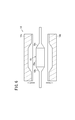
- the vertical mold using the upper mold 14a and the lower mold 14b is exemplified as the balloon molding die 14 (see FIG. 6).
- the mold 110 (see FIG. 8A) using the first mold 110a, the second mold 110b, and the third mold 110c divided horizontally into three parts, or the first mold 112a and the second mold divided into two parts horizontally.
- a mold 112 using 112b (see FIG. 8B), a mold 114 using a first mold 114a, a second mold 114b, and a third mold 114c divided in the circumferential direction (see FIG. 8C),
- the mold 116 (refer FIG. 8D) etc. which engage
- the laser used for heating the balloon material may be other than a wavelength that can be completely absorbed by the balloon material.
- the balloon material can be heated to a desired temperature by being absorbed to some extent by the balloon material. Anything is acceptable.
Landscapes
- Health & Medical Sciences (AREA)
- Engineering & Computer Science (AREA)
- Manufacturing & Machinery (AREA)
- Life Sciences & Earth Sciences (AREA)
- Mechanical Engineering (AREA)
- Heart & Thoracic Surgery (AREA)
- Pulmonology (AREA)
- Biophysics (AREA)
- Child & Adolescent Psychology (AREA)
- Anesthesiology (AREA)
- Biomedical Technology (AREA)
- Hematology (AREA)
- Animal Behavior & Ethology (AREA)
- General Health & Medical Sciences (AREA)
- Public Health (AREA)
- Veterinary Medicine (AREA)
- Media Introduction/Drainage Providing Device (AREA)
Abstract
本発明は、バルーンの製造方法に関し、例えば、製造装置(12)を用いたバルーン(10)の製造方法は、管状のバルーン素材(16)を金型(14)内に配置する工程と、金型(14)を透過し且つバルーン素材(16)に吸収される波長のレーザ(L)を金型内に配置したバルーン素材(16)に照射しながら、該バルーン素材(16)に加圧装置(20)から内圧を付与することにより、バルーン素材(16)を所望の形状のバルーン(10)に成型する工程とを有する。
Description
本発明は、生体器官内の狭窄部の処置等を行うバルーンカテーテルに適用されるバルーンの製造方法に関する。
例えば、心筋梗塞や狭心症の治療では、冠動脈の病変部(狭窄部)をバルーンカテーテルにより押し広げる方法が行われており、他の血管、胆管、気管、食道、尿道、その他の臓器等の生体器官内に形成された狭窄部の改善についても同様に行われることがある。バルーンカテーテルは、一般的に、長尺なシャフト本体と、該シャフト本体の先端側に設けられて径方向に拡張するバルーンとを備えて構成され、先行するガイドワイヤが挿通されることで体内の狭窄部へと送られる。
バルーンカテーテルに用いられるバルーンの製造方法としては、樹脂性材料からなる筒状のチューブ(バルーン素材)を所望形状の金型内に配置し、金型自体を加熱しながら、チューブに加圧流体による内圧と引張装置による延伸力とを付与することにより、該チューブを膨張させて所望の形状に成型(成形)する方法が一般的である。
一方、特表2005-521569号公報には、バルーン素材であるパリソンにマイクロ波を照射して所定温度まで加熱した後、加熱されたパリソンを金型内に配置すると共に、加圧流体を供給し、金型形状に沿ってパリソンを膨張させて所望形状からなるバルーンを成型する方法が開示されている。
バルーンは、通常、病変部の拡張に寄与する筒部(ストレート部)とその両端のテーパ部とから構成される。ところが、上記した従来方法のように、加熱した金型や加熱したバルーン素材を金型内に配置した状態で該バルーン素材に内圧や延伸力を付与して一度に膨らませる成型方法では、バルーンの部位毎の成型形状の違い、例えば筒部とテーパ部との間での膨張距離や加熱状態の違いにより、バルーン全体を均質な肉厚で成型することが難しいという問題がある。
図9Aは、従来方法で成型されたバルーン100の一例を示す側面断面図である。このバルーン100では、病変部の拡張に供される筒部100aに対し、その前後のテーパ部100b、100cの肉厚が厚く成型されている。加熱した金型や加熱したバルーン素材を金型内で一気に膨らませるため、径方向への膨出距離が短いテーパ部100b、100cは、筒部100aよりも膨張される距離が短く、必然的に厚肉になるからである。
従って、このように成型されたバルーン100を折り畳むと、図9Bに示すように、テーパ部100b、100cに対応した先端及び基端の径が大きく山状となるため、病変部の通過性能が低下する可能性がある。
このように、上記のような従来方法では、バルーンの部位毎の成型形状の違いによる膨張距離や加熱状態の違いにより、バルーン全体を所望の肉厚で成型することが難しく、換言すれば、バルーンの部位毎の特性に応じて成型条件を変化させることが難しいことから、機能性を有する特殊な形状のバルーンを成型すること等も困難である。
本発明はこのような従来の課題を考慮してなされたものであり、バルーン全体を所望の肉厚や所望の形状で成型することができるバルーンの製造方法を提供することを目的とする。
本発明に係るバルーンの製造方法は、バルーンカテーテルに用いられるバルーンの製造方法であって、管状のバルーン素材を金型内に配置する工程と、前記金型を透過し且つ前記バルーン素材に吸収される波長のレーザを前記金型内に配置したバルーン素材に照射しながら、前記バルーン素材に内圧を付与することにより、前記バルーン素材を所望の形状のバルーンに成型する工程とを有することを特徴とする。
このような方法によれば、金型内に配置したバルーン素材に対し、該金型を透過し且つバルーン素材に吸収される波長のレーザを照射及び走査しつつ、該バルーン素材に内圧を付与することにより、前記内圧や、レーザによる加熱範囲、加熱角度や延伸量等を加工条件(パラメータ)として、適宜設定・制御しながらバルーン成型を行うことができる。このため、従来方法のように、加熱した金型や加熱したバルーン素材を金型内に配置した状態で該バルーン素材に内圧や延伸力を付与して一度に膨らませる成型方法に比べて、所望のバルーン形状に応じた多様な条件設定が可能となり、より精密なバルーン成型が可能となる。しかも、レーザによりバルーン素材の加熱範囲を極めて狭い範囲に限定することができるため、バルーンの部位毎の形状に応じた最適な成型が可能となり、バルーン全体を所望の均一な肉厚や所望の形状で成型することが可能となる。
この場合、前記バルーンの成型部位に応じて、前記レーザの出力又は前記内圧を変化させることにより、バルーンの各部位の性状要求により最適な成型が可能となる。
また、前記金型が透明又は半透明であると、バルーンの成型時に金型内部でのバルーン成型の状態を外部から観察しながら行うことができる。このため、従来のように、熱電対での間接的な温度測定に併せて、加熱部をサーモグラフ等を用いて可視化することも可能であるので、より高度な分析、条件出しが可能となる。
前記バルーンに成型する工程では、前記レーザを、前記バルーン素材の軸心に交差する方向に照射しながら、前記バルーン素材の軸方向に沿って走査させると、バルーン素材を局所的に順次軸方向に沿って加熱することができる。
この場合、前記レーザの照射源を、前記金型内に配置される前記バルーン素材の軸心を中心として、放射方向に1以上配置し、各照射源を前記バルーン素材の軸方向に沿って移動させるように構成すると、バルーン素材に対するより均等な加熱が可能となる。
なお、前記レーザとして、CO2レーザ、エルビウムYAGレーザ、COレーザ、ネオジウムYAGレーザ又は半導体レーザを用いてもよく、また、前記金型は、レーザを吸収し難い酸化マグネシウム又は単結晶サファイア又はセレン化亜鉛を含んでもよい。そうすると、レーザを金型を透過させてバルーン素材に対して確実に吸収させることができる。
また、前記バルーンに成型する工程では、前記バルーン素材を軸方向に延伸させることで、一層円滑にバルーン素材を変形させ、成型することができる。
以下、本発明に係るバルーンの製造方法について、この製造方法を実施する製造装置との関係で好適な実施の形態を挙げ、添付の図面を参照しながら説明する。
図1は、本発明の一実施形態に係るバルーン10の製造方法を実施する製造装置12の一例を示すブロック構成図である。本実施形態に係る製造方法により製造されるバルーン10は、長尺なシャフト(図示せず)の先端に接合されることで、生体器官、例えば冠動脈に挿通され、狭窄部(病変部)で拡張されることで該狭窄部を押し広げて治療する、いわゆるPTCA(Percutaneous Transluminal Coronary Angioplasty:経皮的冠動脈形成術)拡張カテーテルや、他の血管、胆管、気管、食道、尿道、その他の臓器等の生体器官内に形成された病変部の改善のためのカテーテル等に用いられる。
図1に示すように、製造装置12は、上型14a及び下型14bを有する金型14のキャビティ14c内に配置された管状のバルーン素材16を該キャビティ14cの壁面に沿って加熱・膨張させ、所望形状のバルーン10として成型(成形)するための装置である。
製造装置12は、金型14と、金型14のキャビティ14c内に配置されたバルーン素材16に対して金型14の外側から該金型14を透過させてレーザLを照射する3台のレーザ照射装置(照射源)18a、18b、18cと、成型時にバルーン素材16の内側に両端側から加圧流体(例えば、窒素ガス)を圧送する加圧装置20、20と、成型中のバルーン素材16を両端方向に延伸させるために該バルーン素材16の両端側を互いの離間方向に引っ張る引張装置22、22と、成型時にバルーン素材16の温度を検出する温度センサ23と、製造装置12の全体的な制御を行うコントローラ(制御部)24とを備える。
バルーン素材16は、レーザ照射装置18a~18cからのレーザLによる局所的な加熱と、加圧装置20及び引張装置22による加圧及び引張作用とにより、キャビティ14cの壁面に沿って膨張され、所望の拡張形状を有するバルーン10を形成する。バルーン素材16は、例えば、ポリオレフィン(例えば、ポリエチレン、ポリプロピレン、ポリブテン、エチレン-プロピレン共重合体、エチレン-酢酸ビニル共重合体、アイオノマー、或いはこれら二種以上の混合物等)、ポリ塩化ビニル、ポリアミド、ポリアミドエラストマー、ポリウレタン、ポリウレタンエラストマー、ポリイミド、フッ素樹脂等の高分子材料或いはこれらの混合物で形成されたチューブとして構成される。
例えば、バルーン10として、内圧の変化により折り畳み及び拡張が可能であり、所定の拡張用流体により筒状(円筒状)に拡張する筒部(ストレート部)10aと、筒部10aの先端側で漸次縮径する先端テーパ部10bと、筒部10aの基端側で漸次縮径する基端テーパ部10cとを有する形状のもの(図6参照)を成型する際に、該バルーン10の拡張時の大きさが、筒部10aの外径が1mm~20mm程度、好ましくは1mm~12mm程度、長さが5mm~500mm程度、好ましくは5mm~200mm程度として設定するものとした場合、バルーン素材16の外径は、0.2mm~6mm程度、好ましくは0.2mm~4mm程度、長さが5mm~500mm程度、好ましくは5mm~200mm程度のチューブとして構成される。
各レーザ照射装置18a~18cは、キャビティ14c内に配置されたバルーン素材16の軸心に対して直交した放射方向に等間隔で設置されており(図4B参照)、バルーン素材16の軸方向に同時に走査可能である。レーザ照射装置18a~18cは、レーザLを照射するレーザヘッド26と、レーザヘッド26から照射されたレーザLのスポットを帯状に変形させてバルーン素材16へと導くエクスパンドレンズ28とを備える。
なお、レーザ照射装置は、3台以外、例えば1~2台又は4台以上としてもよいが、1~2台とした場合には、バルーン素材16の周面への確実な照射を可能とするため、レーザ照射装置及びバルーン素材16(金型14)を周方向に相対的に回転させるとよい。
レーザ照射装置18a~18cから照射されるレーザLは、バルーン素材16を局所的に逐次加熱及び逐次拡張させるため、該バルーン素材16が吸収可能な波長のものを用いる必要がある。そこで、上記のような材質からなるバルーン素材16に対しては、例えば、CO2レーザ(波長5.8μm)、エルビウム(Erebium)YAGレーザ(波長2.9μm)、COレーザ(波長9.2μm~10.8μm)、ネオジウムYAGレーザ(波長1.06μm)や半導体レーザ(波長0.65μm~0.98μm)等を用いるとよい。
金型14は、上型14aと下型14bとの間に形成されるキャビティ14cでバルーン10の拡張部位(筒部10a、先端テーパ部10b及び基端テーパ部10c)の成型を行うものである。金型14は、その外側に配置されたレーザ照射装置18a~18cからのレーザLを透過させ、内部のバルーン素材16に吸収させることができるように構成されている必要がある。そこで、金型14は、上記例示したCO2レーザやエルビウムYAGレーザ等が透過可能、つまりレーザを吸収し難い材質、例えば、酸化マグネシウム(MgO)やセレン化亜鉛(ZnSe)、単結晶サファイア等で形成されるとよい。さらに、これらの材料で金型14を構成すると、金型14を透明又は半透明に形成することができ、後述するバルーン10の成型時に金型14内部でのバルーン成型(バルーン素材16の変形)の状態を外部から観察しながら行うことができる。このため、温度センサ23として、間接的な温度測定を行う熱電対等と併せて、レーザLによる加熱部を可視化できるサーモグラフ等を用いることもできるので、後述する製造方法において、その加工条件等のより高度な分析、条件出しが可能となる。
加圧装置20は、金型14内でレーザ照射装置18a~18cによって加熱されて膨張可能な状態にあるバルーン素材16の内側に加圧流体を圧送することにより、金型14の形状に合わせて内側から膨張させるための装置である。引張装置22は、加圧装置20によって膨張されるバルーン素材16を両端側に引張させることにより、レーザLによって加熱されている部分のバルーン素材16を延伸させ、加圧装置20の加圧流体による変形を補助するためのものである。コントローラ24は、予め設定されたバルーン素材16からバルーン10への加工条件に基づき、レーザ照射装置18a~18c、加圧装置20、引張装置22及びその他の補機等を駆動制御するものである。なお、加圧装置20や引張装置22は、図1等では左右一対で図示しているが、勿論、それぞれ1台の装置によってバルーン素材16の左右両側から加圧や延伸を行うように構成してもよい。
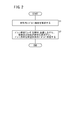
次に、本実施形態に係るバルーン10の製造方法について、図2のフローチャートを参照しながら説明する。
図2のステップS1において、金型14内、つまり上型14aと下型14bの間に形成されるキャビティ14c内に円筒状のバルーン素材16を配置する(図3参照)。
次に、ステップS2において、コントローラ24の制御下に、予め設定されたバルーン10の製造条件に基づき、金型14内に配置されたバルーン素材16の内側(円筒管腔)に加圧装置20から加圧流体を圧送すると共に、引張装置22によりバルーン素材16を両端方向に延伸させながら、レーザ照射装置18a~18cをバルーン素材16の軸方向に走査させつつレーザLを照射して、バルーン素材16を所望形状のバルーン10へと成型する。
すなわち、先ず、図4A及び図4Bに示すように、バルーン素材16を内部に配置した金型14を中心として、レーザ照射装置18a~18cを放射状に配置する。さらに、引張装置22でバルーン素材16の両端をクランプすると共に、加圧装置20の加圧流体供給用の配管をバルーン素材16の両端側に接続する。
次いで、図5A及び図5Bに示すように、レーザ照射装置18a~18cをバルーン素材16の軸方向に走査しながら金型14を透過させてレーザLをバルーン素材16に対して照射する。この際、レーザLは、各レーザ照射装置18a~18cからエクスパンドレンズ28を介してバルーン素材16の周方向に対して同時に照射され、バルーン素材16の軸方向に対しては所定幅の帯状とされていることにより、バルーン素材16は、その軸方向で所定幅の範囲のみが局所的に、つまりレーザLの走査に伴って輪切り状に順次連続加熱される。
従って、バルーン素材16は、レーザLにより局所的に加熱されている部位のみが、引張装置22からの延伸力と、加圧装置20からの加圧流体による内圧とにより、金型14のキャビティ14cの形状に沿って膨張され(図5A及び図5B参照)、レーザLの走査に沿ってバルーン素材16が軸方向で一端側から他端側へと向かって次第にバルーン10に成型される。
この際、コントローラ24の制御下に、バルーン10の部位毎に加工条件(パラメータ)を適宜変更制御する。例えば、筒部10aの成型時よりも先端テーパ部10bや基端テーパ部10cの成型時において、加圧装置20による内圧と引張装置22による延伸力とを増大させると共に、テーパの軸心からの距離が離間するに伴って内圧及び遠心力を次第に低減することにより、図5Bに示すように、略均一な肉厚からなる筒部10a、先端テーパ部10b及び基端テーパ部10cを有するバルーン10を成型することができる。なお、このような内圧及び延伸力の制御と共に、形状がやや複雑な先端テーパ部10bや基端テーパ部10cでのレーザLの走査速度を形状が簡単な筒部10aよりも低減する等の制御を行うと、より均一で適正な肉厚からなるバルーン10を成型することができる。
最終的にレーザLのバルーン素材16の軸方向への走査が完了すると、バルーン10の成型が完了し、金型14を開くことにより、所望の形状からなるバルーン10を取り出すことができる(図6参照)。
本実施形態では、上記のように、バルーン素材16はレーザLが照射されている局所部位のみが加熱され、該加熱された部位のみが加圧装置20及び引張装置22による内圧及び延伸力を受けて膨張し、これがバルーン素材16の軸方向に沿って連続的に行われる。
従って、バルーン成型に係る加工条件(パラメータ)として、温度センサ23による温度、加圧装置20による圧力、及び引張装置22による延伸距離と共に、さらに、レーザLの加熱範囲(部分加熱)、加熱角度(レーザLのバルーン素材16の軸心に対する照射角度)、レーザLの照射タイミング、及びレーザ照射装置18a~18cの走査速度(移動速度)を用いることができる。このように成型時のパラメータが増加したことにより、本実施形態では所望のバルーン形状に応じた多様な条件設定が可能となり、しかも、レーザLによって加熱範囲を極めて狭い範囲に限定することができるため、バルーン10の部位毎の形状(筒部10a、先端テーパ部10b及び基端テーパ部10c等)に応じた最適且つ多様な成型が可能となる。
例えば、成型するバルーン10について、先端テーパ部10bの肉厚を薄くしたり、筒部10aの肉厚を適宜変化させる等、部分的に肉厚を変化させることが可能となる。また、レーザLの出力を適宜変化させることにより、成型時の加熱温度を部分的に変更し、バルーン10の拡張部位を多段に構成することも可能となる。レーザLの照射部位別に加圧装置20による内圧を変化させることにより、例えば、バルーン10の先端側ほど薄肉で柔軟に構成して、バルーン10の体内での挿通性を向上させることもできる。
すなわち、図7Aに示すように、バルーン10について、筒部10aの肉厚を厚くすると共に、先端テーパ部10b及び基端テーパ部10cを薄肉化することも可能である。そうすると、図示しないステントを筒部10aの外周に締め付けた場合等のピンホールや損傷の発生を防止すると共に、先端テーパ部10b及び基端テーパ部10cの柔軟性を向上させて、体内での挿通性や折り畳み性を向上させることができる。この場合には、薄肉にする先端テーパ部10b及び基端テーパ部10cについて、成型時の加圧装置20や引張装置22による加圧力や延伸力を強めに設定すると共に、加熱温度を高めに設定するとよい。
図7Bに示すように、バルーン10について、先端テーパ部10b及び基端テーパ部10cを薄肉化すると共に、筒部10aの肉厚をパルス的に変化させた凹凸形状とすることも可能である。そうすると、筒部10aに図示しないステントをマウントした際に、該ステントの脱落防止効果を得ることができる。この場合にも、薄肉にする部位の成型時の加圧装置20や引張装置22による加圧力や延伸力を強めに設定すると共に、加熱温度を高めに設定する一方、筒部10aの肉厚を厚くする部分については、加圧力や延伸力を弱めに設定すると共に、加熱温度を低めに設定するとよい。なお、筒部10aを上記のように凹凸形状とする以外にも、格子形状や、前記ステントのマスクを挟んでレーザLを照射して該ステントの模様(網目模様等)をバルーンに係止し、これによりステントの脱落防止効果を付与することも可能である。
図7Cに示すように、バルーン10について、筒部10aを2個設けると共に、その間に縮径した部分を設けることも可能である。そうすると、各筒部10a、10aにそれぞれステント(図示せず)をマウントすることができ、一度で2本のステント留置が可能となり、手技時間の短縮やコストダウンが可能となる。この場合には、2個の筒部10aの間の谷部では、加圧装置20や引張装置22による加圧力や延伸力を低減又は省略した設定とするとよい。なお、筒部10aは2個以上としてもよく、また各筒部10aの拡張径を変化させ、拡張径の異なる筒部10aが複数存在する構造とすることもできる。
図7Dに示すように、バルーン10の先端側から基端側へと(図7Dでは、左側から右側へと)、段階的に又は傾斜的に肉厚が変化するように、例えば、バルーン10の先端から先端テーパ部10bまでを最も薄肉とし、筒部10aから基端テーパ部10cまでの肉厚を多少厚くし、基端テーパ部10cから基端側の肉厚をさらに厚くすることもできる。そうすると、先端側が柔軟で狭窄部等の通過性が高く、基端側に適度な剛性(コシ)が付与されて操作性の高いバルーン10を容易に得ることができる。この場合にも、薄肉にする部位の成型時の加圧装置20や引張装置22による加圧力や延伸力を強めに設定すると共に、加熱温度を高めに設定する一方、筒部10aの肉厚を確保する部分については、加圧力や延伸力を弱めに設定すると共に、加熱温度を低めに設定するとよい。
勿論、本実施形態に係る成型方法を用いることにより、図7A~図7Dに示す以外の多様な形状からなるバルーン10を成型することができ、例えば、バルーン10の図示しないカテーテルシャフトへの接合部(基端側接合部)を薄肉化し、通常厚くなり易い接合部での肉厚を最小限とすることもできる。また、成型型レンズ加工により、バルーン10の表面又は内面の形状に変化を付けることもできる。さらに、バルーン10を構成する筒部10a、先端テーパ部10b及び基端テーパ部10cを個別に成型することも容易であり、この場合には成型した各部を融着等によって接合すればよい。換言すれば、バルーン素材として、チューブ状のもの以外、例えば、フィルムを丸めてレーザ融着でバルーンとして成型することも可能である。
以上のように、本実施形態に係るバルーン10の製造方法によれば、金型14内に配置したバルーン素材16に対し、該金型14を透過し且つバルーン素材16に吸収される波長のレーザLを照射及び走査しつつ、加圧装置20による内圧の付与及び引張装置22による軸方向への延伸を行うことにより、バルーン素材16を所望形状のバルーン10として成型する。
従って、温度センサ23による温度、加圧装置20による圧力、及び引張装置22による延伸距離と共に、さらに、レーザLの加熱範囲、加熱角度、レーザLの照射タイミング、及びレーザ照射装置18a~18cの走査速度等をバルーン成型時のパラメータとして、適宜設定・制御しながらバルーン成型を行うことができるため、所望のバルーン形状に応じた多様な条件設定が可能となる。しかも、レーザLによりバルーン素材16の加熱範囲を極めて狭い範囲に限定することができるため、バルーン10の部位毎の形状に応じた最適な成型が可能となる。すなわち、レーザLによる局所加熱により、バルーン10の各部(筒部10a等)の設定形状に応じて、上記各パラメータを適宜制御することで、バルーン10全体として肉厚を精密に制御して均一な肉厚に形成することができる一方、必要に応じて肉厚を適宜変化させた特殊な形状からなるバルーン10を成型することが可能となる。
本発明は、上述の実施の形態に限らず、本発明の要旨を逸脱することなく、種々の構成乃至工程を採り得ることは勿論である。
例えば、上記実施形態では、レーザ加熱中のバルーン成型について、加圧装置による内圧及び引張装置による延伸力を付与するものとして説明したが、バルーンの成型条件によっては、加圧装置による内圧の付与のみによって十分にバルーン素材を膨張・成型することができる。
また、上記実施形態では、バルーン成型用の金型14として、上型14aと下型14bとを用いた縦割り型のものを例示したが(図6参照)、これ以外であっても勿論よく、例えば、横割りで3分割の第1型110a、第2型110b及び第3型110cを用いた金型110(図8A参照)や、横割りで2分割の第1型112a及び第2型112bを用いた金型112(図8B参照)や、周方向で3分割の第1型114a、第2型114b及び第3型114cを用いた金型114(図8C参照)や、筒状の第1型116aの両端開口にテーパ状部分を有する第2型116b及び第3型116cを嵌め込む金型116(図8D参照)等であってもよい。
バルーン素材の加熱に供されるレーザとしては、バルーン素材に完全に吸収可能な波長のもの以外でもよく、例えば、ある程度バルーン素材に吸収されることにより、該バルーン素材を所望の温度まで加熱可能なものであればよい。
Claims (8)
- バルーンカテーテルに用いられるバルーンの製造方法であって、
管状のバルーン素材(16)を金型(14)内に配置する工程と、
前記金型(14)を透過し且つ前記バルーン素材(16)に吸収される波長のレーザを前記金型(14)内に配置したバルーン素材(16)に照射しながら、前記バルーン素材(16)に内圧を付与することにより、前記バルーン素材(16)を所望の形状のバルーン(10)に成型する工程と、
を有することを特徴とするバルーンの製造方法。 - 請求項1記載のバルーンの製造方法において、
前記バルーン(10)の成型部位に応じて、前記レーザの出力又は前記内圧を変化させることを特徴とするバルーンの製造方法。 - 請求項1記載のバルーンの製造方法において、
前記金型(14)は、透明又は半透明であることを特徴とするバルーンの製造方法。 - 請求項1~3のいずれか1項に記載のバルーンの製造方法において、
前記バルーン(10)に成型する工程では、前記レーザを、前記バルーン素材(16)の軸心に交差する方向に照射しながら、前記バルーン素材(16)の軸方向に沿って走査させることを特徴とするバルーンの製造方法。 - 請求項4記載のバルーンの製造方法において、
前記レーザの照射源(18a、18b、18c)を、前記金型(14)内に配置される前記バルーン素材(16)の軸心を中心として、放射方向に1以上配置し、各照射源(18a、18b、18c)を前記バルーン素材(16)の軸方向に沿って移動させることを特徴とするバルーンの製造方法。 - 請求項1記載のバルーンの製造方法において、
前記レーザとして、CO2レーザ、エルビウムYAGレーザ、COレーザ、ネオジウムYAGレーザ又は半導体レーザを用いることを特徴とするバルーンの製造方法。 - 請求項1記載のバルーンの製造方法において、
前記金型(14)は、酸化マグネシウム又は単結晶サファイア又はセレン化亜鉛を含むことを特徴とするバルーンの製造方法。 - 請求項1記載のバルーンの製造方法において、
前記バルーン(10)に成型する工程では、前記バルーン素材(16)を軸方向に延伸させることを特徴とするバルーンの製造方法。
Priority Applications (1)
| Application Number | Priority Date | Filing Date | Title |
|---|---|---|---|
| JP2012501752A JP5502986B2 (ja) | 2010-02-25 | 2011-02-16 | バルーンの製造方法 |
Applications Claiming Priority (2)
| Application Number | Priority Date | Filing Date | Title |
|---|---|---|---|
| JP2010040757 | 2010-02-25 | ||
| JP2010-040757 | 2010-02-25 |
Publications (1)
| Publication Number | Publication Date |
|---|---|
| WO2011105267A1 true WO2011105267A1 (ja) | 2011-09-01 |
Family
ID=44506681
Family Applications (1)
| Application Number | Title | Priority Date | Filing Date |
|---|---|---|---|
| PCT/JP2011/053289 Ceased WO2011105267A1 (ja) | 2010-02-25 | 2011-02-16 | バルーンの製造方法 |
Country Status (2)
| Country | Link |
|---|---|
| JP (1) | JP5502986B2 (ja) |
| WO (1) | WO2011105267A1 (ja) |
Cited By (8)
| Publication number | Priority date | Publication date | Assignee | Title |
|---|---|---|---|---|
| JP2015061551A (ja) * | 2013-09-21 | 2015-04-02 | 住友ベークライト株式会社式会社 | 内視鏡用ガイドチューブ |
| CN110339465A (zh) * | 2019-08-14 | 2019-10-18 | 巢湖学院 | 一种介入医疗双球囊的模具芯模 |
| JP2020520291A (ja) * | 2018-01-02 | 2020-07-09 | アイメディコム | カテーテル用風船の製造治具及びこれを利用した風船の製造方法 |
| CN112203712A (zh) * | 2018-07-09 | 2021-01-08 | 株式会社戈德曼 | 球囊导管 |
| JP2021052963A (ja) * | 2019-09-27 | 2021-04-08 | ニプロ株式会社 | バルーンカテーテル |
| CN114073609A (zh) * | 2020-07-31 | 2022-02-22 | 赛诺医疗科学技术股份有限公司 | 一种球囊预处理设备以及球囊预处理方法 |
| JP2023085377A (ja) * | 2017-11-30 | 2023-06-20 | コーニング インコーポレイテッド | 延伸ブロー成形ピペットならびに延伸ブロー成形ピペットを成形するためのシステムおよび方法 |
| WO2025211398A1 (ja) * | 2024-04-04 | 2025-10-09 | 株式会社カネカ | バルーンカテーテル用バルーン及びバルーンカテーテル用バルーンの製造方法 |
Citations (3)
| Publication number | Priority date | Publication date | Assignee | Title |
|---|---|---|---|---|
| JP2005001383A (ja) * | 2003-05-20 | 2005-01-06 | Frontier:Kk | プラスチック容器の製造方法、プリフォームの加熱方法およびプラスチック容器の加熱方法 |
| JP2006129978A (ja) * | 2004-11-04 | 2006-05-25 | Kaneka Corp | カテーテルバルーンの製造方法 |
| JP2007098163A (ja) * | 1996-01-11 | 2007-04-19 | Boston Scientific Scimed Inc | 体内挿入可能かつ膨張可能な処理デバイスを作製するための方法 |
-
2011
- 2011-02-16 JP JP2012501752A patent/JP5502986B2/ja not_active Expired - Fee Related
- 2011-02-16 WO PCT/JP2011/053289 patent/WO2011105267A1/ja not_active Ceased
Patent Citations (3)
| Publication number | Priority date | Publication date | Assignee | Title |
|---|---|---|---|---|
| JP2007098163A (ja) * | 1996-01-11 | 2007-04-19 | Boston Scientific Scimed Inc | 体内挿入可能かつ膨張可能な処理デバイスを作製するための方法 |
| JP2005001383A (ja) * | 2003-05-20 | 2005-01-06 | Frontier:Kk | プラスチック容器の製造方法、プリフォームの加熱方法およびプラスチック容器の加熱方法 |
| JP2006129978A (ja) * | 2004-11-04 | 2006-05-25 | Kaneka Corp | カテーテルバルーンの製造方法 |
Cited By (11)
| Publication number | Priority date | Publication date | Assignee | Title |
|---|---|---|---|---|
| JP2015061551A (ja) * | 2013-09-21 | 2015-04-02 | 住友ベークライト株式会社式会社 | 内視鏡用ガイドチューブ |
| JP2023085377A (ja) * | 2017-11-30 | 2023-06-20 | コーニング インコーポレイテッド | 延伸ブロー成形ピペットならびに延伸ブロー成形ピペットを成形するためのシステムおよび方法 |
| JP7561908B2 (ja) | 2017-11-30 | 2024-10-04 | コーニング インコーポレイテッド | 延伸ブロー成形ピペットならびに延伸ブロー成形ピペットを成形するためのシステムおよび方法 |
| JP2020520291A (ja) * | 2018-01-02 | 2020-07-09 | アイメディコム | カテーテル用風船の製造治具及びこれを利用した風船の製造方法 |
| CN112203712A (zh) * | 2018-07-09 | 2021-01-08 | 株式会社戈德曼 | 球囊导管 |
| CN112203712B (zh) * | 2018-07-09 | 2023-11-07 | 株式会社戈德曼 | 球囊导管 |
| CN110339465A (zh) * | 2019-08-14 | 2019-10-18 | 巢湖学院 | 一种介入医疗双球囊的模具芯模 |
| JP2021052963A (ja) * | 2019-09-27 | 2021-04-08 | ニプロ株式会社 | バルーンカテーテル |
| JP7380018B2 (ja) | 2019-09-27 | 2023-11-15 | ニプロ株式会社 | バルーンカテーテル |
| CN114073609A (zh) * | 2020-07-31 | 2022-02-22 | 赛诺医疗科学技术股份有限公司 | 一种球囊预处理设备以及球囊预处理方法 |
| WO2025211398A1 (ja) * | 2024-04-04 | 2025-10-09 | 株式会社カネカ | バルーンカテーテル用バルーン及びバルーンカテーテル用バルーンの製造方法 |
Also Published As
| Publication number | Publication date |
|---|---|
| JP5502986B2 (ja) | 2014-05-28 |
| JPWO2011105267A1 (ja) | 2013-06-20 |
Similar Documents
| Publication | Publication Date | Title |
|---|---|---|
| JP5502986B2 (ja) | バルーンの製造方法 | |
| JP4795976B2 (ja) | 体内挿入可能かつ膨張可能な処理デバイスを作製するための方法 | |
| EP2056915B1 (en) | Refoldable balloon and method of making the same | |
| JP5756109B2 (ja) | ポリマーチューブからステントをレーザ加工するためのレーザパワーの設定 | |
| JP3924320B2 (ja) | 膨張性ポリエチレン・テレフタレートバルーンの製造方法 | |
| JP5895017B2 (ja) | 高い強度および柔軟性を有するバルーンカテーテルシャフトおよびその製造方法 | |
| EP2089087B1 (en) | Medical balloon deflation | |
| US6863856B1 (en) | Slotted mold for making a catheter balloon | |
| US20070112300A1 (en) | Balloon folding design, apparatus and method of making the same | |
| US11813422B2 (en) | Methods of fabricating a heart valve delivery catheter | |
| MXPA97000334A (en) | Laser ablation of angioplas catheters and balls | |
| JP6267214B2 (ja) | 生体再吸収性ステントをクリンプする方法 | |
| JP2002520099A (ja) | 円錐状部の剛性が低減された拡張バルーンを製造する方法 | |
| JP2014188205A (ja) | バルーン、バルーンカテーテル、およびバルーン製造方法 | |
| JP6259560B2 (ja) | バルーンカテーテル用バルーン | |
| EP4591915A1 (en) | Balloon catheter | |
| KR100887988B1 (ko) | 카테터에 사용되는 풍선부재의 제조방법 | |
| JP2011206171A (ja) | バルーンカテーテル及びその製造方法 | |
| JP2003275319A (ja) | カテーテル用バルーンおよびバルーン拡張カテーテル | |
| JP2006129978A (ja) | カテーテルバルーンの製造方法 | |
| JP2018008102A (ja) | バルーン製造方法 | |
| JP2014057792A (ja) | バルーンカテーテル用バルーンの製造方法 | |
| JP2019063138A (ja) | バルーンカテーテル |
Legal Events
| Date | Code | Title | Description |
|---|---|---|---|
| 121 | Ep: the epo has been informed by wipo that ep was designated in this application |
Ref document number: 11747231 Country of ref document: EP Kind code of ref document: A1 |
|
| WWE | Wipo information: entry into national phase |
Ref document number: 2012501752 Country of ref document: JP |
|
| NENP | Non-entry into the national phase |
Ref country code: DE |
|
| 122 | Ep: pct application non-entry in european phase |
Ref document number: 11747231 Country of ref document: EP Kind code of ref document: A1 |