WO2011102435A1 - チタン製水素吸蔵材容器 - Google Patents
チタン製水素吸蔵材容器 Download PDFInfo
- Publication number
- WO2011102435A1 WO2011102435A1 PCT/JP2011/053427 JP2011053427W WO2011102435A1 WO 2011102435 A1 WO2011102435 A1 WO 2011102435A1 JP 2011053427 W JP2011053427 W JP 2011053427W WO 2011102435 A1 WO2011102435 A1 WO 2011102435A1
- Authority
- WO
- WIPO (PCT)
- Prior art keywords
- titanium
- hydrogen
- storage material
- hydrogen storage
- container
- Prior art date
- Legal status (The legal status is an assumption and is not a legal conclusion. Google has not performed a legal analysis and makes no representation as to the accuracy of the status listed.)
- Ceased
Links
Images


Classifications
-
- F—MECHANICAL ENGINEERING; LIGHTING; HEATING; WEAPONS; BLASTING
- F17—STORING OR DISTRIBUTING GASES OR LIQUIDS
- F17C—VESSELS FOR CONTAINING OR STORING COMPRESSED, LIQUEFIED OR SOLIDIFIED GASES; FIXED-CAPACITY GAS-HOLDERS; FILLING VESSELS WITH, OR DISCHARGING FROM VESSELS, COMPRESSED, LIQUEFIED, OR SOLIDIFIED GASES
- F17C11/00—Use of gas-solvents or gas-sorbents in vessels
- F17C11/005—Use of gas-solvents or gas-sorbents in vessels for hydrogen
-
- C—CHEMISTRY; METALLURGY
- C01—INORGANIC CHEMISTRY
- C01B—NON-METALLIC ELEMENTS; COMPOUNDS THEREOF; METALLOIDS OR COMPOUNDS THEREOF NOT COVERED BY SUBCLASS C01C
- C01B3/00—Hydrogen; Gaseous mixtures containing hydrogen; Separation of hydrogen from mixtures containing it; Purification of hydrogen; Reversible storage of hydrogen
- C01B3/0005—Reversible storage of hydrogen, e.g. by hydrogen getters or electrodes
- C01B3/001—Reversible storage of hydrogen, e.g. by hydrogen getters or electrodes characterised by the uptaking media; Treatment thereof
- C01B3/0018—Inorganic elements or compounds, e.g. oxides, nitrides, borohydrides or zeolites; Solutions thereof
- C01B3/0031—Intermetallic compounds; Metal alloys
-
- Y—GENERAL TAGGING OF NEW TECHNOLOGICAL DEVELOPMENTS; GENERAL TAGGING OF CROSS-SECTIONAL TECHNOLOGIES SPANNING OVER SEVERAL SECTIONS OF THE IPC; TECHNICAL SUBJECTS COVERED BY FORMER USPC CROSS-REFERENCE ART COLLECTIONS [XRACs] AND DIGESTS
- Y02—TECHNOLOGIES OR APPLICATIONS FOR MITIGATION OR ADAPTATION AGAINST CLIMATE CHANGE
- Y02E—REDUCTION OF GREENHOUSE GAS [GHG] EMISSIONS, RELATED TO ENERGY GENERATION, TRANSMISSION OR DISTRIBUTION
- Y02E60/00—Enabling technologies; Technologies with a potential or indirect contribution to GHG emissions mitigation
- Y02E60/30—Hydrogen technology
- Y02E60/32—Hydrogen storage
Definitions
- the present invention relates to a titanium hydrogen storage material container that stores a hydrogen storage material such as a hydrogen storage alloy and stores and releases hydrogen from the outside of the container.
- a titanium material has a problem of hydrogen embrittlement in which hydrogen is absorbed in a crystal lattice at a high temperature to form a hydride and embrittle.
- a method for preventing hydrogen embrittlement of the titanium material a method of forming a layer that prevents entry of hydrogen such as a nitride layer on the surface of titanium has been devised (see, for example, Patent Documents 1 to 3).
- a relatively low temperature such as room temperature, the problem of hydrogen embrittlement to titanium is unlikely to occur.
- a container containing a hydrogen storage alloy that absorbs and releases hydrogen at a relatively low temperature such as room temperature. It is considered that a container using a titanium material can be put into practical use without forming a nitride layer or the like as it is or by forming the above layer as necessary without causing hydrogen embrittlement.
- the present invention was made against the background of the above circumstances, and in a titanium container containing a hydrogen storage material such as a hydrogen storage alloy, a titanium hydrogen storage capable of preventing hydrogen embrittlement associated with hydrogen absorption / release.
- An object is to provide a material container.
- the present inventors have found that the above phenomenon is caused by the fact that the hydrogen storage alloy works effectively as a catalyst for dissociating hydrogen molecules into hydrogen atoms, and hydrogen easily enters the titanium material even at room temperature. It is assumed that the titanium material has reached hydrogen embrittlement, and that hydrogen embrittlement cannot be prevented even if a layer that prevents hydrogen intrusion is formed. Further, it is assumed that hydrogen is further solid-phase diffused through the interface between the layer and the container to promote the penetration of hydrogen into the container, and thus the hydrogen embrittlement of the container is caused. It has come to be completed.
- the first present invention is a titanium hydrogen storage material container for storing a hydrogen storage material, wherein the titanium container body and the inner peripheral side of the titanium container body A separator that is interposed between the titanium container body and the hydrogen storage material without being surface-bonded to the titanium container body and prevents contact between the hydrogen storage material and the titanium container body; It is characterized by having.
- the contact between the titanium container body and the hydrogen storage material is prevented by the separator. Moreover, since the separator and the titanium container main body are not surface-bonded, hydrogen that has entered the separator at the interface between the separator and the titanium container main body does not further enter the titanium container main body by solid phase diffusion. . In addition, when hydrogen atoms that have passed through the separator reach the end face of the separator and come into contact with the atmosphere, it becomes easier to recombine and return to hydrogen molecules, and it can be avoided that hydrogen contacts the titanium container body in an atomic state, Hydrogen embrittlement is less likely to occur.
- hydrogen when hydrogen is absorbed and released in an atmosphere such as normal temperature without forced heating or forced cooling, it is possible to reliably prevent hydrogen from entering the titanium container body.
- the separator plate may be prevented from penetrating the hydrogen gas inside the separator plate and moving to the inner side of the titanium container body.
- the hydrogen gas penetrates and moves to the inner side of the titanium vessel body. It is not essential to avoid doing so.
- a relatively low temperature for example, 50 ° C. or less
- it is desirable to secure a sealed structure with a separator so that the hydrogen gas does not come into contact with the titanium container body so that the hydrogen gas stays in this sealed structure. .
- the separator plate since it is necessary to prevent the contact between the hydrogen storage material and the titanium container body on the side wall and bottom surface of the container, the separator plate has a bottomed cylindrical shape along the inner surface shape of the titanium container body. Is desirable. Furthermore, by providing a top plate as necessary, the contact between the hydrogen storage material and the titanium container body can be reliably prevented.
- the bottomed cylindrical shape may be integrally molded, but it surrounds the inner peripheral side along the inner peripheral surface of the titanium container body, and at least both ends in the circumferential direction are arranged without being fixed to each other. It may be constituted by what has a side wall plate and a bottom plate.
- the side wall plate is expanded in diameter by the hydrogen occlusion material expanded by occlusion of hydrogen and effectively makes surface contact with the inner surface of the titanium container main body on the outer peripheral side, the side wall plate is heated through the outer peripheral surface of the titanium container main body.
- the side wall plate and the titanium container body are not surface-bonded, hydrogen hardly diffuses through the solid phase through the boundary between the two.
- the shape of the separator is not limited to a specific one, and any shape that prevents the contact between the hydrogen storage material and the titanium container body may be used.
- the material and thickness of the separator of the present invention are not particularly limited.
- As the material a dense material that prevents the permeation of hydrogen atoms is desirable, and pure aluminum or an aluminum alloy that is light in weight and excellent in processing / deformability and excellent in heat conduction can be suitably used.
- As the thickness of the separator a range of 0.05 to 1 mm can be shown as preferable. When the thickness of the separator is less than 0.05 mm, hydrogen permeation easily occurs, the effect of preventing hydrogen intrusion into the titanium container main body is reduced, and breakage easily occurs along with the hydrogen absorption / release cycle. On the other hand, when the thickness of the separator exceeds 1 mm, the volume ratio of the separator occupying the internal volume increases, and the hydrogen storage amount decreases.
- the hydrogen storage material typically includes a hydrogen storage alloy powder.
- the type of the hydrogen storage material is not limited, and the state of a lump, a powder or the like is not limited. However, it can be said that the effect of the present invention is particularly remarkable in the granular material.
- the hydrogen storage alloy include AB 5 type (LaNi 5 etc.), AB 2 type (TiCr 2 etc.), BCC type (TiCrV etc.), AB type (TiFe etc.), A 2 B type (Mg 2 Ni etc.) and the like. Assuming that the alloy can reversibly absorb and release hydrogen, it is not limited to these.
- the volume filling rate of the storage alloy powder is desirably 40% or more. However, since a filling rate of about 45% is the limit if it is in powder form, it is more desirable to combine it with a resin compounding technology such as those described in Japanese Patent No. 4145339 and Japanese Patent No. 4180105.
- the shape and material of the titanium container main body are not limited to specific ones in the present invention, and any material can be used as long as it is airtight and can accommodate the hydrogen storage material.
- any material can be used as long as it is airtight and can accommodate the hydrogen storage material.
- a cylindrical shape, a spherical shape, a box shape and the like can be mentioned, but the shape is not questioned.
- titanium materials include ⁇ + ⁇ alloys such as Ti-3Al-2.5V, Ti-6Al-4V, Ti-6Al-6V-2Sn, ⁇ alloys such as Ti-5Al-2.5Sn, Ti-6Al Examples include near ⁇ alloys such as -1Mo-1V, ⁇ alloys such as Ti-13V-11Cr-3Al, Ti-8Mo-8V-2Fe-3Al, or corrosion resistant alloys such as pure titanium and Ti-0.5Pb. As mentioned.
- FIG. 3A is a cross-sectional view of a separator of a titanium hydrogen storage material container according to another embodiment of the present invention
- FIG. 3B is an exploded perspective view of a titanium hydrogen storage material container according to another embodiment of the present invention.
- FIG. It is the figure which showed the time-dependent change of the circumferential distortion of the container in the Example of this invention. It is the figure which showed the time-dependent change of the circumferential distortion of the container in the comparative example of this invention.
- the titanium container body 1 made of pure titanium or titanium alloy has a bottomed cylindrical shape, and is open at one end in the axial direction.
- the side wall plate separator 2 prepared to be stored in the titanium container body 1 is made of pure aluminum or aluminum alloy and has a plate thickness in the range of 0.05 to 1 mm.
- the separator plate 2 has substantially the same width as the axial length of the titanium container body 1, and when the separator plate 2 is rolled up and stored on the cylinder inner surface of the titanium container body 1, both end portions in the circumferential direction are Overlapping length (overlap). The amount of overlap can be set as appropriate, and it is desirable that the overlap is not performed.
- the separator 3 for the bottom plate disposed on one end side of the separator 2 is made of the same material as the separator 2 and has a thickness within a range of 0.05 to 1 mm. Further, the separator 3 has a low-height peripheral wall 30 erected so as to substantially overlap the inner peripheral surface when the separator 2 is rolled and stored in the titanium container body 1. By inserting the separator 3 into the separator 2 through the peripheral wall 30, the hydrogen storage alloy can be accommodated.
- the separator plate 2 may be housed in the titanium container body 1 by cutting or bending a single plate according to the shape of the titanium container body 1.
- the separator 3 and the separator 2 are combined and stored in a titanium container body 1.
- the cylindrical separator 2 is in close contact with the inner peripheral surface of the titanium container body 1.
- the outer peripheral surface of the separator plate 2 may be brought into close contact with the inner peripheral surface of the titanium container main body 1 after being stored in the titanium container main body 1 by a spring action to expand the diameter of the separator 2.
- a cylindrical separator 2 housed in a titanium container body 1 is filled with hydrogen storage alloy powder 5.
- a separator 3 is located on the bottom side of the separator 2, and the separators 2 and 3 reliably prevent contact between the hydrogen storage alloy powder 5 and the titanium container body 1.
- the hydrogen storage alloy powder 5 is preferably filled in the voids in the titanium container body 1 at a filling rate (volume%) of 40% or more.
- the titanium container body 1 is filled with the hydrogen storage alloy powder 5 and then covered with a thin plate-like inner lid 6 provided with a hydrogen conduction port 60 so as to close the opening, and further covers the inner lid 6 and is made of titanium.
- a cup-shaped outer lid 7 that seals the container body 1 is joined to the titanium container body 1.
- the inner lid 6 is preferably made of a material that hardly causes hydrogen embrittlement.
- the outer lid 7 can be made of a titanium material, and the outer lid 7 is provided with a hydrogen pipe 70 communicating with the hydrogen conduction port 60. Hydrogen can be transferred between the outside and the titanium container body 1 through the hydrogen pipe 70.
- the titanium hydrogen storage material container of the embodiment of the present invention is configured by the above configuration.
- the hydrogen-occlusion alloy powder 5 expands and acts to expand the diameter of the separator 2, and the surface contact between the separator 2 and the titanium container body 1 becomes closer. Thereafter, hydrogen can be released from the hydrogen-absorbing alloy powder 5 by contact with ambient temperature atmosphere or seawater through the outer peripheral surface of the titanium container body 1. At the time of the absorption and release of hydrogen, hydrogen enters the separators 2 and 3, but there is no solid-phase diffusion from the separators 2 and 3 to the titanium container body 1, and the hydrogen does not enter the titanium container body 1. Invasion is suppressed, and hydrogen embrittlement can be prevented.
- the separator 2 may be formed into a bottomed cylindrical separator 10 as shown in FIG. 3A by integral molding in addition to cutting, rounding, bending and the like of the plate material as described above.
- the separator 10 has a cylindrical side wall part 11 and a bottom part 12 integrated with the side wall part 11.
- the separator 10 is integrally formed by processing such as deep drawing.
- the hydrogen storage alloy powder is stored as described above, and the titanium container body is used by using an inner lid, an outer lid, and the like. 1 is sealed and hydrogen is absorbed and released. Also in the titanium hydrogen storage material container using the separator 10, hydrogen embrittlement of the titanium container main body is prevented and the container can be used as a lightweight container as in the above embodiment.
- a bottomed cylindrical container (outer diameter 34 mm, wall thickness 2 mm, length 80 mm) made of Ti-6Al-4V was prepared as a titanium container body.
- a thin aluminum plate having a thickness of 0.2 mm a side wall plate, a bottom plate, and a lid plate having a shape suitable for the inside of the cylindrical container were produced as separators in the same manner as shown in FIGS.
- the side wall plate was produced by cutting a thin plate into a suitable size, bending it into a cylindrical shape, and overlapping both ends in the circumferential direction.
- the bottom plate and the cover plate were made into a cup shape by deep drawing, and a hydrogen conduction hole was provided in the cover plate.
- the produced side wall plate and bottom plate were inserted into the cylindrical container, and AB type 5 hydrogen storage alloy powder was filled at a filling rate of 55% by volume in terms of the internal volume ratio. Thereafter, a lid plate was put on, and an outer lid made of titanium having a hydrogen introduction tube was put on and sealed. Further, in order to measure the strain of the titanium container body, strain gauges are provided on the outer peripheral surface of the container body at four locations at angles of 0 °, 90 °, 180 °, and 270 ° with respect to the central axis of the cylindrical container. Pasted.
- hydrogen was repeatedly absorbed and released, and the amount of deformation of the container body at that time was measured with the strain gauge.
- Specific conditions for absorbing and releasing hydrogen are as follows. First, after evacuating the container at 80 ° C., activation was performed by introducing 0.99 MPa of hydrogen at 20 ° C. or lower. After activation, a cycle test of 0.99 MPa hydrogen absorption and atmospheric pressure hydrogen release was performed in a 20 ° C. water bath.
- FIG. 4 shows the change over time of the container body strain in this example.
- Table 1 shows the maximum circumferential strain of the container body, the burst pressure, and the hydrogen concentration inside the titanium container body.
- the level of strain was a maximum of 170 ⁇ 10 ⁇ 6 or less at the stage after 35 days, and was within the range of elastic deformation.
- the burst pressure was 125 MPa, which was approximately equal to the calculated value of 124 MPa. From the results of the cross-sectional structure observation, it was confirmed that the same structure as before the test was retained.
- the hydrogen concentration in the titanium container body was 20 ppm before the test, and 34 ppm after the test, which was within the expected range. From the above, it was found that hydrogen embrittlement hardly occurred.
- FIG. 5 shows changes with time in the container body strain in this comparative example.
- Table 1 shows the maximum circumferential strain of the container body, the burst pressure, and the hydrogen concentration inside the titanium container body. The strain gradually increased with time and reached a maximum of 9590 ⁇ 10 ⁇ 6 after 40 days from the test. After 40 days, the test was interrupted, and a water pressure burst test was conducted on the container body. As a result, although the calculated burst pressure was 124 MPa, it broke brittlely at 53 MPa. When the cross-sectional structure of the titanium container body was observed, a hydride layer was observed on the inner surface. The hydrogen concentration in the titanium container body was 20 ppm before the test, and reached 4000 ppm after the test. From the above, it was clear that hydrogen embrittlement occurred.
- the present invention is not limited to the above-described embodiment, and can be appropriately modified and improved.
- the material, shape, dimension, numerical value, form, number, arrangement location, and the like of each component in the above-described embodiment are arbitrary and are not limited as long as the present invention can be achieved.
- the separator that prevents the contact between the hydrogen storage material and the titanium container body is interposed between the hydrogen storage material and the container body, and the titanium container body and the separator are Because it is not surface-bonded, hydrogen atoms generated by the catalytic effect of the hydrogen storage material enter the separator and solid-phase diffuse, and further reach the surface of the container body and prevent it from entering the interior. Hydrogen embrittlement of the container body can be suppressed.
Landscapes
- Chemical & Material Sciences (AREA)
- Engineering & Computer Science (AREA)
- Organic Chemistry (AREA)
- Chemical Kinetics & Catalysis (AREA)
- Combustion & Propulsion (AREA)
- Inorganic Chemistry (AREA)
- Mechanical Engineering (AREA)
- General Engineering & Computer Science (AREA)
- Filling Or Discharging Of Gas Storage Vessels (AREA)
Abstract
水素の吸放出に伴う水素脆化を防止することができるチタン製水素吸蔵材容器を提供することを目的とする。水素吸蔵材(水素吸蔵合金粉末5)を収容するチタン製水素吸蔵材容器において、チタン製容器本体1と、チタン製容器本体1の内周側にあって該チタン製容器本体1と面接合されることなく該チタン製容器本体1と前記水素吸蔵材との間に介在して該水素吸蔵材と前記チタン製容器本体1との接触を妨げる隔離板(側壁板2、底板3)とを有するので、水素吸放出の際に水素吸蔵合金粉末5の触媒効果によって発生した水素原子がチタン製容器本体1の表面に達してさらにチタン製容器本体1の内部に侵入するのを妨げ、チタン製容器本体の水素脆化を抑制する。
Description
本発明は、水素吸蔵合金などの水素吸蔵材を収容して容器外部との間で水素の吸蔵、放出を行うチタン製水素吸蔵材容器に関する。
水素吸蔵合金を収容して水素を吸放出させる容器の材質には、種々の材料が使用されているが、最近では、軽量高強度なチタン材料の使用が検討されている。
一般に、チタン材料は、高温時に水素を結晶格子内に吸収し、水素化物を形成して脆化するという水素脆化の問題がある。このため、チタン材料の水素脆化を防ぐ方法として、チタンの表面に窒化物層などの水素の侵入を防ぐ層を形成する方法が考案されている(例えば特許文献1~3参照)。
一方、常温などの比較的低い温度では、チタンに対する水素脆化の問題は生じにくいものとされており、したがって、常温などの比較的低い温度で水素を吸放出する水素吸蔵合金を収容する容器では、窒化物層などを形成することなくそのまま、または必要に応じて上記層を形成することで、水素脆化を招くことなくチタン材料を用いた容器の実用化が可能であると考えられる。
一般に、チタン材料は、高温時に水素を結晶格子内に吸収し、水素化物を形成して脆化するという水素脆化の問題がある。このため、チタン材料の水素脆化を防ぐ方法として、チタンの表面に窒化物層などの水素の侵入を防ぐ層を形成する方法が考案されている(例えば特許文献1~3参照)。
一方、常温などの比較的低い温度では、チタンに対する水素脆化の問題は生じにくいものとされており、したがって、常温などの比較的低い温度で水素を吸放出する水素吸蔵合金を収容する容器では、窒化物層などを形成することなくそのまま、または必要に応じて上記層を形成することで、水素脆化を招くことなくチタン材料を用いた容器の実用化が可能であると考えられる。
しかし、本発明者らの研究によれば、水素吸蔵合金をチタン合金製容器に充填し、室温で水素吸放出を行ったにも拘わらず、経時的にチタン合金製容器の水素脆化が進行することが分かった。
この水素脆化現象は、室温のような比較的低い温度で進行したため、先行文献が対象としているような高温における水素ガスとチタン合金の反応とは異なる現象であると考えられる。すなわち、単なる水素ガスとの接触によって水素脆化が発生するのではなく、水素吸蔵合金の介在により、水素脆化速度が非常に大きくなったものと考えられる。また、本発明者らの研究によれば、チタン合金製容器の内面に窒化物層などの水素の侵入を防ぐ層を形成して室温で水素の吸放出を行っても、上記と同様に容器に水素脆化が生じることが分かった。
この水素脆化現象は、室温のような比較的低い温度で進行したため、先行文献が対象としているような高温における水素ガスとチタン合金の反応とは異なる現象であると考えられる。すなわち、単なる水素ガスとの接触によって水素脆化が発生するのではなく、水素吸蔵合金の介在により、水素脆化速度が非常に大きくなったものと考えられる。また、本発明者らの研究によれば、チタン合金製容器の内面に窒化物層などの水素の侵入を防ぐ層を形成して室温で水素の吸放出を行っても、上記と同様に容器に水素脆化が生じることが分かった。
本願発明は、上記事情を背景としてなされたものであり、水素吸蔵合金などの水素吸蔵材を収容するチタン製容器において、水素の吸放出に伴う水素脆化を防止することができるチタン製水素吸蔵材容器を提供することを目的とする。
本発明者らは、鋭意研究した結果、上記現象の原因としては、水素吸蔵合金が水素分子を水素原子に解離する触媒として効果的に働いて、室温においてもチタン材料中に水素が侵入しやすくなり、チタン材料の水素脆化に至ったと想定されること、また、水素の侵入を防ぐ層を形成しても水素脆化を防止できないのは、該層に水素が侵入して固相拡散し、さらに該層と容器との界面を介してさらに水素が固相拡散することで容器への水素の侵入を助長し、よって容器の水素脆化を招いたと想定されることから、本発明を完成するに至ったものである。
すなわち、本発明のチタン製水素吸蔵材容器のうち、第1の本発明は、水素吸蔵材を収容するチタン製水素吸蔵材容器において、チタン製容器本体と、該チタン製容器本体の内周側にあって該チタン製容器本体と面接合されることなく該チタン製容器本体と前記水素吸蔵材との間に介在して該水素吸蔵材と前記チタン製容器本体との接触を妨げる隔離板とを有することを特徴とする。
本発明によれば、チタン製容器本体と水素吸蔵材とが隔離板で接触が妨げられる。しかも、隔離板とチタン製容器本体とは面接合されていないため、隔離板とチタン製容器本体の界面において隔離板を侵入した水素が固相拡散によってさらにチタン製容器本体に侵入することはない。また、隔離板を透過した水素原子が隔離板端面に至って雰囲気に触れる際に再結合して水素分子に戻りやすくなり、原子状の状態でチタン製容器本体に水素が接触することを回避でき、水素脆化が一層起こりにくくなる。
これにより水素がチタン製容器本体に侵入するのを妨げることができる。特に強制加熱や強制冷却を伴わない常温のような雰囲気で水素の吸放出を行わせる場合には、確実にチタン製容器本体に水素が侵入するのを防止することができる。
なお、隔離板は、隔離板内部の水素ガスが浸透してチタン製容器本体内面側に移動しないようにしてもよいが、本発明としては水素ガスが浸透してチタン製容器本体内面側に移動することを回避することが必須とされるものではない。特に常温のように比較的低い温度(例えば50℃以下)で水素の吸放出を行う場合には、水素ガスとチタン製容器本体との接触は大きな問題にならない。ただし、高温で水素ガスを扱う場合には、水素ガスとチタン製容器本体とが接触しないように、隔離板で密閉構造を確保し、この密閉構造内に水素ガスが留まるようにするのが望ましい。
なお、隔離板は、隔離板内部の水素ガスが浸透してチタン製容器本体内面側に移動しないようにしてもよいが、本発明としては水素ガスが浸透してチタン製容器本体内面側に移動することを回避することが必須とされるものではない。特に常温のように比較的低い温度(例えば50℃以下)で水素の吸放出を行う場合には、水素ガスとチタン製容器本体との接触は大きな問題にならない。ただし、高温で水素ガスを扱う場合には、水素ガスとチタン製容器本体とが接触しないように、隔離板で密閉構造を確保し、この密閉構造内に水素ガスが留まるようにするのが望ましい。
なお、隔離板は、容器の側壁および底面において水素吸蔵材とチタン製容器本体との接触を妨げることが必要となるので、チタン製容器本体の内面形状に沿った有底の筒形状とするものが望ましい。さらに、必要に応じて天板を備えることで、水素吸蔵材とチタン製容器本体との接触を確実に妨げることができる。
また、上記有底筒形状は一体成形したものが挙げられるが、チタン製容器本体の内周面に沿って内周側を囲み、かつ少なくとも周方向両端部を互いに固定することなく重ねて配置された側壁板と、底板とを有するものによって構成するものであってもよい。
該側壁板は、水素を吸蔵して膨張した水素吸蔵材によって拡径動作が生じ、外周側のチタン製容器本体内面に効果的に面接触するようにすれば、チタン製容器本体外周面を通して熱交換を行う際に、熱伝導効率を高める効果がある。この際にも、側壁板とチタン製容器本体とは面接合されているものではないので、両者の境界を通して水素が固相拡散することは殆どない。ただし、本発明としては隔離板の形状が特定のものに限定されるものではなく、水素吸蔵材とチタン製容器本体との接触を妨げるものであればよい。
また、上記有底筒形状は一体成形したものが挙げられるが、チタン製容器本体の内周面に沿って内周側を囲み、かつ少なくとも周方向両端部を互いに固定することなく重ねて配置された側壁板と、底板とを有するものによって構成するものであってもよい。
該側壁板は、水素を吸蔵して膨張した水素吸蔵材によって拡径動作が生じ、外周側のチタン製容器本体内面に効果的に面接触するようにすれば、チタン製容器本体外周面を通して熱交換を行う際に、熱伝導効率を高める効果がある。この際にも、側壁板とチタン製容器本体とは面接合されているものではないので、両者の境界を通して水素が固相拡散することは殆どない。ただし、本発明としては隔離板の形状が特定のものに限定されるものではなく、水素吸蔵材とチタン製容器本体との接触を妨げるものであればよい。
さらに、本発明の隔離板の材質、厚さなどは特に限定されるものではない。材質としては、水素原子の透過が妨げられる密な材料が望ましく、さらには軽量で加工・変形性の優れた熱伝導が良好な純アルミニウムまたはアルミニウム合金を好適に用いることができる。隔離板の厚さとしては0.05~1mmの範囲を好適なものとして示すことができる。隔離板の厚さが0.05mm未満であると、水素の透過がしやすく、チタン製容器本体に対する水素侵入の防止効果が小さくなるとともに、水素吸放出サイクルに伴って破損しやすくなる。また、隔離板の厚さが1mmを超えると、内容積に占める隔離板の体積比が大きくなるため、水素貯蔵量が低下してしまう。
前記水素吸蔵材は、代表的には水素吸蔵合金粉末が挙げられる。ただし、本発明としては水素吸蔵材の種別が限定されるものではなく、塊状物、粉粒物などの状態も限定されるものではない。ただし、本発明の効果は粉粒物において特に顕著であるといえる。
水素吸蔵合金としては、AB5型(LaNi5など)、AB2型(TiCr2など)、BCC型(TiCrVなど)、AB型(TiFeなど)、A2B型(Mg2Niなど)などが想定されるが、可逆的に水素を吸放出できる合金であれば、これらに限定しない。
水素貯蔵密度をできるだけ高くするため、吸蔵合金粉末の体積充填率は40%以上であるのが望ましい。ただし、粉末のままでは充填率45%程度が限界であるため、日本国特許第4145339号や日本国特許第4180105号に挙げるような樹脂複合化技術と組み合わせるのがより望ましい。
水素吸蔵合金としては、AB5型(LaNi5など)、AB2型(TiCr2など)、BCC型(TiCrVなど)、AB型(TiFeなど)、A2B型(Mg2Niなど)などが想定されるが、可逆的に水素を吸放出できる合金であれば、これらに限定しない。
水素貯蔵密度をできるだけ高くするため、吸蔵合金粉末の体積充填率は40%以上であるのが望ましい。ただし、粉末のままでは充填率45%程度が限界であるため、日本国特許第4145339号や日本国特許第4180105号に挙げるような樹脂複合化技術と組み合わせるのがより望ましい。
また、チタン製容器本体の形状、材質も本発明としては特定のものに限定されるものではなく、気密にして水素吸蔵材を収容できるものであればよい。例えば、円筒形、球形、箱型などが挙げられるが、形状を問うものではない。また、チタン材料としては、Ti-3Al-2.5V、Ti-6Al-4V、Ti-6Al-6V-2Snのようなα+β合金、Ti-5Al-2.5Snのようなα合金、Ti-6Al-1Mo-1Vのようなニアα合金、Ti-13V-11Cr-3Al、Ti-8Mo-8V-2Fe-3Alのようなβ合金、あるいは純チタンやTi-0.5Pbのような耐食合金が例として挙げられる。
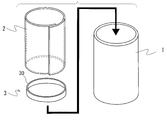
以下に、本発明の一実施形態を図1に基づいて説明する。
純チタンまたはチタン合金製のチタン製容器本体1は、有底円筒形状を有しており、軸方向一端側は開口している。
該チタン製容器本体1に収納するべく用意される側壁板用の隔離板2は、純アルミニウムまたはアルミニウム合金からなり、0.05~1mmの範囲内の板厚を有している。該隔離板2は、チタン製容器本体1の軸方向長さとほぼ同じ幅を有し、筒状に丸めてチタン製容器本体1の筒内面に重ねて収納した際に、周方向の両端部が重なる長さ(重ねしろ)を有している。重ねしろ量は適宜設定することができ、該重ねしろでは互いに接合することは行わないのが望ましい。
また、隔離板2の一端側に配置される底板用の隔離板3は、前記隔離板2と同材料からなり、0.05~1mmの範囲内の板厚を有している。また、隔離板3は、前記隔離板2をチタン製容器本体1に丸めて収納した際に、その内周面にほぼ重なるように立設した低い高さの周囲壁30を有しており、該隔離板3を周囲壁30を介して隔離板2に内挿することで水素吸蔵合金の収容が可能になる。なお、隔離板2は、チタン製容器本体1の形状に合わせて一枚板を切断したり折り曲げたりしてチタン製容器本体1内に収納するようにしてもよい。
純チタンまたはチタン合金製のチタン製容器本体1は、有底円筒形状を有しており、軸方向一端側は開口している。
該チタン製容器本体1に収納するべく用意される側壁板用の隔離板2は、純アルミニウムまたはアルミニウム合金からなり、0.05~1mmの範囲内の板厚を有している。該隔離板2は、チタン製容器本体1の軸方向長さとほぼ同じ幅を有し、筒状に丸めてチタン製容器本体1の筒内面に重ねて収納した際に、周方向の両端部が重なる長さ(重ねしろ)を有している。重ねしろ量は適宜設定することができ、該重ねしろでは互いに接合することは行わないのが望ましい。
また、隔離板2の一端側に配置される底板用の隔離板3は、前記隔離板2と同材料からなり、0.05~1mmの範囲内の板厚を有している。また、隔離板3は、前記隔離板2をチタン製容器本体1に丸めて収納した際に、その内周面にほぼ重なるように立設した低い高さの周囲壁30を有しており、該隔離板3を周囲壁30を介して隔離板2に内挿することで水素吸蔵合金の収容が可能になる。なお、隔離板2は、チタン製容器本体1の形状に合わせて一枚板を切断したり折り曲げたりしてチタン製容器本体1内に収納するようにしてもよい。
図1に示すように、上記隔離板3と隔離板2とは組み合わされて、チタン製容器本体1内に収納される。筒状とされた隔離板2は、チタン製容器本体1の内周面にほぼ密着する。また、隔離板2の拡径しようとするばね作用によってチタン製容器本体1に収納した後に隔離板2の外周面がチタン製容器本体1の内周面に確実に密着するようにしてもよい。
チタン製容器本体1に収納された筒状の隔離板2内には水素吸蔵合金粉末5が充填される。隔離板2の底部側には隔離板3が位置しており、隔離板2、3によって、水素吸蔵合金粉末5とチタン製容器本体1との接触は確実に妨げられる。この際に水素吸蔵合金粉末5は、チタン製容器本体1内の空隙に対し、好適には40%以上の充填率(体積%)で充填する。
チタン製容器本体1に収納された筒状の隔離板2内には水素吸蔵合金粉末5が充填される。隔離板2の底部側には隔離板3が位置しており、隔離板2、3によって、水素吸蔵合金粉末5とチタン製容器本体1との接触は確実に妨げられる。この際に水素吸蔵合金粉末5は、チタン製容器本体1内の空隙に対し、好適には40%以上の充填率(体積%)で充填する。
上記チタン製容器本体1は、水素吸蔵合金粉末5を充填した後、開口を塞ぐように、水素導通口60を設けた薄板状の内蓋6を被せ、さらに、内蓋6を覆ってチタン製容器本体1を密閉するカップ形状の外蓋7をチタン製容器本体1に接合する。内蓋6は、好ましくは、水素脆化が生じにくい材料で構成する。外蓋7はチタン材料で構成することができ、該外蓋7には、前記水素導通口60に連通する水素配管70が設けられている。該水素配管70を通して外部とチタン製容器本体1との間で水素の移動が可能になっている。上記構成によって本発明の実施形態のチタン製水素吸蔵材容器が構成されている。
上記チタン製水素吸蔵材容器では、例えば、高圧の水素ガスを水素配管70を通してチタン製容器本体1内に導入し、水素吸蔵合金粉末5に水素を吸蔵させる。この吸蔵によって水素吸蔵合金粉末5は膨張し、隔離板2を拡径する作用が働き、隔離板2とチタン製容器本体1との面接触がより緊密になる。
その後は、チタン製容器本体1の外周面を通した常温の雰囲気や海水などの接触によって水素吸蔵合金粉末5からの水素放出が可能になる。
上記水素の吸放出の際に、水素は隔離板2、3へと侵入するものの、隔離板2、3からチタン製容器本体1への固相拡散はなく、チタン製容器本体1への水素の侵入が抑制され、よって水素脆化を防ぐことができる。
その後は、チタン製容器本体1の外周面を通した常温の雰囲気や海水などの接触によって水素吸蔵合金粉末5からの水素放出が可能になる。
上記水素の吸放出の際に、水素は隔離板2、3へと侵入するものの、隔離板2、3からチタン製容器本体1への固相拡散はなく、チタン製容器本体1への水素の侵入が抑制され、よって水素脆化を防ぐことができる。
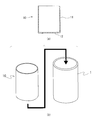
また、隔離板2は、上記のように板材の切断、丸め、折り曲げ等の他に、一体成形によって、図3(a)に示すように有底筒形状の隔離板10としてもよい。該隔離板10は、図3(a)に示すように、筒状の側壁部11と該側壁部11と一体になった底部12とを有している。隔離板10は、深絞り等の加工によって一体に成形される。
該隔離板10は、チタン製容器本体1に収納した際に、該チタン製容器本体1と側壁部11の外周面とがほぼ接触するように外径が設定されている。図3(b)に示すように、チタン製容器本体1に隔離板10を収納した後、上記のように、水素吸蔵合金粉末を収容し、中蓋、外蓋などを用いてチタン製容器本体1を密閉し、水素の吸放出を行う。
該隔離板10を用いたチタン製水素吸蔵材容器においても、上記実施形態と同様に、チタン製容器本体の水素脆化が防止され、軽量な容器として使用することができる。
該隔離板10は、チタン製容器本体1に収納した際に、該チタン製容器本体1と側壁部11の外周面とがほぼ接触するように外径が設定されている。図3(b)に示すように、チタン製容器本体1に隔離板10を収納した後、上記のように、水素吸蔵合金粉末を収容し、中蓋、外蓋などを用いてチタン製容器本体1を密閉し、水素の吸放出を行う。
該隔離板10を用いたチタン製水素吸蔵材容器においても、上記実施形態と同様に、チタン製容器本体の水素脆化が防止され、軽量な容器として使用することができる。
なお、上記実施形態は、本発明の一例にすぎず、本発明の趣旨を逸脱しないものであれば、その形態を特に限定するものではない。
以下に、本発明の実施例を説明する。
チタン製容器本体として、Ti-6Al-4V製の有底円筒容器(外径34mm、肉厚2mm、長さ80mm)を用意した。次に、厚さ0.2mmのアルミニウム製薄板を用いて、図1、2に示すものと同様に、隔離板として該円筒容器内部に合う形状の側壁板、底板、および蓋板を作製した。側壁板は、薄板を適したサイズに切断し、これを円筒状に曲げ、周方向の両端部を重ね合わせることで作製した。底板および蓋板は深絞り加工によりカップ形状に作製し、蓋板には水素導通孔を設けた。
次に、作製した側壁板および底板を前記円筒容器内部に挿入し、AB5型水素吸蔵合金粉末を内容積比で55体積%の充填率で充填した。その後、蓋板を被せ、水素導入管を有するチタン製の外蓋を被せて密閉した。
さらに、上記チタン製容器本体の歪みを測定するため、該容器本体外周面に、円筒容器の中心軸に対して0°、90°、180°、270°の角度となる4箇所に歪みゲージを貼り付けた。
チタン製容器本体として、Ti-6Al-4V製の有底円筒容器(外径34mm、肉厚2mm、長さ80mm)を用意した。次に、厚さ0.2mmのアルミニウム製薄板を用いて、図1、2に示すものと同様に、隔離板として該円筒容器内部に合う形状の側壁板、底板、および蓋板を作製した。側壁板は、薄板を適したサイズに切断し、これを円筒状に曲げ、周方向の両端部を重ね合わせることで作製した。底板および蓋板は深絞り加工によりカップ形状に作製し、蓋板には水素導通孔を設けた。
次に、作製した側壁板および底板を前記円筒容器内部に挿入し、AB5型水素吸蔵合金粉末を内容積比で55体積%の充填率で充填した。その後、蓋板を被せ、水素導入管を有するチタン製の外蓋を被せて密閉した。
さらに、上記チタン製容器本体の歪みを測定するため、該容器本体外周面に、円筒容器の中心軸に対して0°、90°、180°、270°の角度となる4箇所に歪みゲージを貼り付けた。
上記水素吸蔵材容器において、水素の吸放出を繰り返し、そのときの容器本体変形量を前記歪みゲージにより計測した。具体的な水素の吸放出の条件は以下のとおりである。まず、80℃で該容器を真空引きした後、20℃以下で0.99MPaの水素を導入して活性化を行った。活性化後、20℃の水槽で0.99MPa水素吸収⇔大気圧水素放出のサイクル試験を行った。
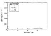
図4に本実施例における容器本体歪みの経時変化を示す。また、表1に容器本体の最大周方向歪み、バースト圧およびチタン製容器本体内部の水素濃度を示す。
歪みのレベルは35日後の段階で最大170×10-6以下であり、弾性変形の範囲内に収まった。35日後に試験を中断し、容器本体の水圧バースト試験をしたところ、バースト圧は125MPaとなり、計算値の124MPaとほぼ一致した。断面の組織観察の結果からも、試験前と同じ組織を保持していることが確認された。チタン製容器本体中における水素濃度は、試験前が20ppmであるところ、試験後は34ppmであり、予測される範囲に収まった。以上より、水素脆化が殆ど起きていないことが分かった。
歪みのレベルは35日後の段階で最大170×10-6以下であり、弾性変形の範囲内に収まった。35日後に試験を中断し、容器本体の水圧バースト試験をしたところ、バースト圧は125MPaとなり、計算値の124MPaとほぼ一致した。断面の組織観察の結果からも、試験前と同じ組織を保持していることが確認された。チタン製容器本体中における水素濃度は、試験前が20ppmであるところ、試験後は34ppmであり、予測される範囲に収まった。以上より、水素脆化が殆ど起きていないことが分かった。
(比較例)
実施例と同じTi-6Al-4V製の円筒容器(外径34mm、肉厚2mm、長さ80mm)をチタン製容器本体として用意し、その内部に、隔離板としての前記アルミニウム製薄板を挿入せずに、直接、AB5型水素吸蔵合金粉末を内容積比で55体積%の充填率で詰めた。他の条件は実施例と同じにして、水素吸放出のサイクル試験を行い、歪み変化を測定した。
実施例と同じTi-6Al-4V製の円筒容器(外径34mm、肉厚2mm、長さ80mm)をチタン製容器本体として用意し、その内部に、隔離板としての前記アルミニウム製薄板を挿入せずに、直接、AB5型水素吸蔵合金粉末を内容積比で55体積%の充填率で詰めた。他の条件は実施例と同じにして、水素吸放出のサイクル試験を行い、歪み変化を測定した。
図5に本比較例における容器本体歪みの経時変化を示す。また、表1に容器本体の最大周方向歪み、バースト圧およびチタン製容器本体内部の水素濃度を示す。
歪みは時間とともに徐々に増加し、試験から40日後には最大9590×10-6にまで達した。40日後に試験を中断し、容器本体の水圧バースト試験をしたところ、計算バースト圧は124MPaであるのにも拘わらず、53MPaで脆性的に破断した。チタン製容器本体の断面組織を観察すると、水素化物層が内面に認められた。チタン製容器本体中における水素濃度は、試験前が20ppmであるところ、試験後は4000ppmに達していた。以上より、水素脆化が起きたことは明らかであった。
歪みは時間とともに徐々に増加し、試験から40日後には最大9590×10-6にまで達した。40日後に試験を中断し、容器本体の水圧バースト試験をしたところ、計算バースト圧は124MPaであるのにも拘わらず、53MPaで脆性的に破断した。チタン製容器本体の断面組織を観察すると、水素化物層が内面に認められた。チタン製容器本体中における水素濃度は、試験前が20ppmであるところ、試験後は4000ppmに達していた。以上より、水素脆化が起きたことは明らかであった。

以上のように、アルミニウムの薄板を水素吸蔵合金とチタン製容器本体との間に、面接合することなく介在させることで、効果的に水素脆化を抑制できることが確認された。
本発明は、上述した実施形態に限定されるものではなく、適宜、変形、改良等が自在である。その他、上述した実施形態における各構成要素の材質、形状、寸法、数値、形態、数、配置場所、等は本発明を達成できるものであれば任意であり、限定されない。
本発明を詳細にまた特定の実施態様を参照して説明したが、本発明の精神と範囲を逸脱することなく様々な変更や修正を加えることができることは当業者にとって明らかである。
本出願は、2010年2月19日出願の日本特許出願(特願2010-034944)に基づくものであり、その内容はここに参照として取り込まれる。
以上のように、本発明によれば、水素吸蔵材とチタン製容器本体との接触を妨げる隔離板を水素吸蔵材と該容器本体の間に介在させ、かつチタン製容器本体と隔離板とを面接合させていないため、水素吸蔵材の触媒効果によって発生した水素原子が隔離板に侵入して固相拡散し、さらに該容器本体表面に達して内部に侵入することを妨げ、結果としてチタン製容器本体の水素脆化を抑制することができる。
1 チタン製容器本体
2 隔離板
3 隔離板
5 水素吸蔵合金粉末
10 隔離板
11 側壁部
12 底部
2 隔離板
3 隔離板
5 水素吸蔵合金粉末
10 隔離板
11 側壁部
12 底部
Claims (9)
- 水素吸蔵材を収容するチタン製水素吸蔵材容器において、チタン製容器本体と、該チタン製容器本体の内周側にあって該チタン製容器本体と面接合されることなく該チタン製容器本体と前記水素吸蔵材との間に介在して該水素吸蔵材と前記チタン製容器本体との接触を妨げる隔離板とを有するチタン製水素吸蔵材容器。
- 前記隔離板は、前記チタン製容器本体の内面形状に沿って有底の筒形状を有する請求項1記載のチタン製水素吸蔵材容器。
- 前記隔離板は、一体成形されたものである請求項2記載のチタン製水素吸蔵材容器。
- 前記隔離板は、チタン製容器本体の内周面に沿って内周側を囲み、かつ少なくとも周方向両端部を互いに固定することなく重ねて配置された側壁板と、底板とを有する請求項2記載のチタン製水素吸蔵材容器。
- 前記隔離板の前記側壁板は、少なくとも前記水素吸蔵材の水素吸蔵時に前記チタン製容器本体内周面に面接触するように配置されている請求項4記載のチタン製水素吸蔵材容器。
- 前記隔離板は、純アルミニウムまたはアルミニウム合金からなる請求項1~5のいずれか1項に記載のチタン製水素吸蔵材容器。
- 前記隔離板は、厚さ0.05~1mmである請求項1~6のいずれか1項に記載のチタン製水素吸蔵材容器。
- 前記チタン製容器本体の外周面を通して熱交換されるものである請求項1~7のいずれか1項に記載のチタン製水素吸蔵材容器。
- 前記水素吸蔵材が、充填率40%以上で前記チタン製容器本体内に収容される水素吸蔵合金粉末である請求項1~8のいずれか1項に記載のチタン製水素吸蔵材容器。
Applications Claiming Priority (2)
| Application Number | Priority Date | Filing Date | Title |
|---|---|---|---|
| JP2010-034944 | 2010-02-19 | ||
| JP2010034944A JP5637429B2 (ja) | 2010-02-19 | 2010-02-19 | チタン製水素吸蔵材容器 |
Publications (1)
| Publication Number | Publication Date |
|---|---|
| WO2011102435A1 true WO2011102435A1 (ja) | 2011-08-25 |
Family
ID=44483021
Family Applications (1)
| Application Number | Title | Priority Date | Filing Date |
|---|---|---|---|
| PCT/JP2011/053427 Ceased WO2011102435A1 (ja) | 2010-02-19 | 2011-02-17 | チタン製水素吸蔵材容器 |
Country Status (2)
| Country | Link |
|---|---|
| JP (1) | JP5637429B2 (ja) |
| WO (1) | WO2011102435A1 (ja) |
Cited By (1)
| Publication number | Priority date | Publication date | Assignee | Title |
|---|---|---|---|---|
| JP2011169420A (ja) * | 2010-02-19 | 2011-09-01 | Japan Steel Works Ltd:The | チタン製水素吸蔵材容器 |
Families Citing this family (2)
| Publication number | Priority date | Publication date | Assignee | Title |
|---|---|---|---|---|
| US20200002163A1 (en) * | 2017-01-31 | 2020-01-02 | Japan Blue Energy Co., Ltd. | Hydrogen occlusion cartridge |
| KR102722446B1 (ko) * | 2022-06-29 | 2024-10-25 | 정대호 | 교체형 수소카트리지 용기 |
Citations (3)
| Publication number | Priority date | Publication date | Assignee | Title |
|---|---|---|---|---|
| JP2004100926A (ja) * | 2002-09-13 | 2004-04-02 | Japan Metals & Chem Co Ltd | 水素吸蔵合金収納容器及び該容器の製造方法 |
| JP2007278482A (ja) * | 2006-04-12 | 2007-10-25 | Toyota Motor Corp | 水素タンク |
| JP2008291862A (ja) * | 2007-05-22 | 2008-12-04 | Toyota Motor Corp | 金属部材、水素貯蔵タンクおよびグラファイト被覆金属の製造方法 |
Family Cites Families (4)
| Publication number | Priority date | Publication date | Assignee | Title |
|---|---|---|---|---|
| JPS59146901A (ja) * | 1983-02-08 | 1984-08-23 | Sekisui Chem Co Ltd | 金属水素化物反応容器及びその製造方法 |
| JPH1160201A (ja) * | 1997-08-04 | 1999-03-02 | Sanritsuku:Kk | 水素吸蔵合金の貯蔵容器 |
| JP4686865B2 (ja) * | 2001-02-05 | 2011-05-25 | ソニー株式会社 | 水素吸蔵放出装置 |
| JP5637429B2 (ja) * | 2010-02-19 | 2014-12-10 | 株式会社日本製鋼所 | チタン製水素吸蔵材容器 |
-
2010
- 2010-02-19 JP JP2010034944A patent/JP5637429B2/ja not_active Expired - Fee Related
-
2011
- 2011-02-17 WO PCT/JP2011/053427 patent/WO2011102435A1/ja not_active Ceased
Patent Citations (3)
| Publication number | Priority date | Publication date | Assignee | Title |
|---|---|---|---|---|
| JP2004100926A (ja) * | 2002-09-13 | 2004-04-02 | Japan Metals & Chem Co Ltd | 水素吸蔵合金収納容器及び該容器の製造方法 |
| JP2007278482A (ja) * | 2006-04-12 | 2007-10-25 | Toyota Motor Corp | 水素タンク |
| JP2008291862A (ja) * | 2007-05-22 | 2008-12-04 | Toyota Motor Corp | 金属部材、水素貯蔵タンクおよびグラファイト被覆金属の製造方法 |
Cited By (1)
| Publication number | Priority date | Publication date | Assignee | Title |
|---|---|---|---|---|
| JP2011169420A (ja) * | 2010-02-19 | 2011-09-01 | Japan Steel Works Ltd:The | チタン製水素吸蔵材容器 |
Also Published As
| Publication number | Publication date |
|---|---|
| JP2011169420A (ja) | 2011-09-01 |
| JP5637429B2 (ja) | 2014-12-10 |
Similar Documents
| Publication | Publication Date | Title |
|---|---|---|
| CA1093984A (en) | Hydride container | |
| KR101448572B1 (ko) | 유체 인클로저 및 그것에 관한 방법 | |
| CN101672422B (zh) | 加压储氢罐的防渗透产品及方法 | |
| JP5760000B2 (ja) | 金属水素化物を有する水素貯蔵タンク | |
| US20110302933A1 (en) | Storage and supply system of liquefied and condensed hydrogen | |
| CN101910703A (zh) | 储氢罐 | |
| CN101413624B (zh) | 一种金属氢化物贮氢装置及其制造方法 | |
| WO2008033740A3 (en) | Mitigating hydrogen flux through solid and liquid barrier materials | |
| US10511039B2 (en) | Solid state hydrogen storage device and solid state hydrogen storage system | |
| JP5637429B2 (ja) | チタン製水素吸蔵材容器 | |
| JP2004530628A (ja) | ハイブリッド状態で水素を貯蔵する方法 | |
| US10989359B2 (en) | Hydrogen storage tank comprising a plurality of seals | |
| US8481151B2 (en) | Hydrogen storage alloy and hydrogen storage unit using same | |
| WO2023004000A1 (en) | Non-pyrophoric hydrogen storage alloys and hydrogen storage systems using the alloys | |
| RU2267694C1 (ru) | Емкость для хранения водорода | |
| Tao et al. | Fluorite transition metal hydride induced destabilization of the MgH 2 system in MgH 2/TMH 2 multilayers (TM= Sc, Ti, V, Cr, Y, Zr, Nb, La, Hf) | |
| WO2007008105A1 (fr) | Recipient de stockage d'hydrogene (et variantes) | |
| JP2015522139A (ja) | タンク | |
| KR100673149B1 (ko) | 잠수함 | |
| CN201339807Y (zh) | 一种贮氢器 | |
| WO2016019316A1 (en) | Hydrogen gas storage tank with supporting filter tube(s) | |
| CN201140984Y (zh) | 多元材料储氢装置 | |
| JP2008531445A (ja) | 水素貯蔵構造体 | |
| JP2004261739A (ja) | 水素吸蔵複合材料 | |
| JP4098043B2 (ja) | 水素吸蔵合金収納容器の製造方法 |
Legal Events
| Date | Code | Title | Description |
|---|---|---|---|
| 121 | Ep: the epo has been informed by wipo that ep was designated in this application |
Ref document number: 11744721 Country of ref document: EP Kind code of ref document: A1 |
|
| NENP | Non-entry into the national phase |
Ref country code: DE |
|
| 122 | Ep: pct application non-entry in european phase |
Ref document number: 11744721 Country of ref document: EP Kind code of ref document: A1 |