WO2011102403A1 - Embrayage unidirectionnel - Google Patents
Embrayage unidirectionnel Download PDFInfo
- Publication number
- WO2011102403A1 WO2011102403A1 PCT/JP2011/053333 JP2011053333W WO2011102403A1 WO 2011102403 A1 WO2011102403 A1 WO 2011102403A1 JP 2011053333 W JP2011053333 W JP 2011053333W WO 2011102403 A1 WO2011102403 A1 WO 2011102403A1
- Authority
- WO
- WIPO (PCT)
- Prior art keywords
- engagement
- outer ring
- power transmission
- axial direction
- way clutch
- Prior art date
- Legal status (The legal status is an assumption and is not a legal conclusion. Google has not performed a legal analysis and makes no representation as to the accuracy of the status listed.)
- Ceased
Links
Images


Classifications
-
- F—MECHANICAL ENGINEERING; LIGHTING; HEATING; WEAPONS; BLASTING
- F16—ENGINEERING ELEMENTS AND UNITS; GENERAL MEASURES FOR PRODUCING AND MAINTAINING EFFECTIVE FUNCTIONING OF MACHINES OR INSTALLATIONS; THERMAL INSULATION IN GENERAL
- F16D—COUPLINGS FOR TRANSMITTING ROTATION; CLUTCHES; BRAKES
- F16D41/00—Freewheels or freewheel clutches
- F16D41/06—Freewheels or freewheel clutches with intermediate wedging coupling members between an inner and an outer surface
- F16D41/064—Freewheels or freewheel clutches with intermediate wedging coupling members between an inner and an outer surface the intermediate members wedging by rolling and having a circular cross-section, e.g. balls
Definitions
- the present invention relates to a one-way clutch.
- the one-way clutch includes an outer ring, an inner ring, a plurality of engagement rollers, a coil spring, and a plurality of bolts.
- Each of the engagement rollers is disposed between the engagement cam surface of the outer ring and the engagement surface of the inner ring in a state of being biased in one direction by a coil spring.
- the plurality of engaging rollers are located at intervals in the circumferential direction.
- the outer ring has a plurality of bolt holes. After the bolts are inserted into the bolt holes of the outer ring, the outer ring is fixed to the crankshaft by tightening it on the end face of the crankshaft so that rotational power is transmitted between the outer ring and the crankshaft. Yes.
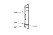
- an inlay portion 307 is provided on one end face in the axial direction of the outer ring 304, and a substantially disc-shaped power transmission member 306 is fitted into the inlay portion 307 by an inlay, and the outer ring There is a one-way clutch in which 304 and a power transmission member 306 are fixed by a plurality of bolts 309.
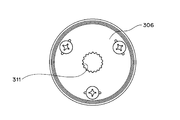
- a female spline 311 is formed at the center of the power transmission member 306, and a male spline formed on the outer peripheral surface of the crankshaft is spline-fitted to the female spline 311.
- a one-way clutch that transmits power between the outer ring 304 and the crankshaft.
- This one-way clutch has an advantage that power can be transmitted stably and smoothly because power is transmitted by spline fitting.
- the runout accuracy of the spline 311, the runout accuracy of the spigot diameter, and the runout accuracy of the inner ring / outer diameter / cam groove of the outer ring 304 affect the overall eccentricity, and it is difficult to increase the accuracy of the concentricity. is there.
- One of the objects of the present invention is to provide a one-way clutch capable of omitting the bolt and improving the accuracy of concentricity.
- An outer ring having an engagement cam surface and an engagement recess opening on one side in the axial direction on the inner peripheral surface;
- An inner ring having an engagement surface on the outer peripheral surface;
- An engagement element disposed between the engagement cam surface of the outer ring and the engagement surface of the inner ring;
- a biasing member that biases the engagement element in one direction;
- a power transmission member that closes at least a part of an opening on one side in the axial direction between the outer ring and the inner ring, and that transmits rotational power of the outer ring to a shaft member;
- the engaging recess has an engaging portion on one side in the axial direction of the engaging element,
- the power transmission member includes a movement prevention engagement portion that engages with the engagement portion of the engagement recess and prevents movement of the power transmission member in the circumferential direction with respect to the outer ring.
- the movement preventing engagement portion of the power transmission member is engaged with the engagement portion of the engagement recess of the outer ring, and the power transmission member is circumferentially moved with respect to the outer ring. Therefore, the bolt for fixing the power transmission member to the outer ring can be omitted, the number of parts can be reduced, and the manufacturing cost can be reduced.
- FIG. 4 is a sectional view taken along line AA ′ in FIG. 3.
- FIG. 4 is a sectional view taken along line BB ′ in FIG. 3.
- FIG. 1 is a schematic configuration diagram of a starter clutch which is an embodiment of the one-way clutch of the present invention.
- the starter clutch includes a starter motor 1, an idler gear 2, an inner ring 3, an outer ring 4, a plurality of engagement rollers 5 as an example of an engagement element, a plurality of coil springs as an example of an urging member, A transmission member 6 and a plate member 7 are provided.
- the power transmission member 6 is a disk-shaped member and closes an opening on one side in the axial direction between the inner ring 3 and the outer ring 4.
- the power transmission member 6 has a female spline at the center.
- the female spline of the power transmission member 6 is spline-fitted to a male spline formed on the outer peripheral surface of a crankshaft 8 as an example of a shaft member.
- the power transmission member 6 is not rotatable relative to the outer ring 4.
- the plate member 7 is a disk-like member and closes the opening on the other side in the axial direction between the inner ring 3 and the outer ring 4.
- This starter clutch transmits the rotational power of the starter motor 1 to the inner ring 3 engaged with the pinion of the idler gear 2 via the idler gear 2. Further, the rotational power transmitted to the inner ring 3 is transmitted to the outer ring 4 via the engaging rollers 5. Further, the rotational power transmitted to the outer ring 4 is transmitted to the crankshaft 8 via the power transmission member 6. In this way, the rotational power of the starter motor 1 is transmitted to the crankshaft 8.
- FIG. 2 shows the outer ring 4, the engaging roller 5, the coil spring 10 and the plate member 7 of the one-way clutch outside on the side opposite to the plate member 7 side in the axial direction (outward on one side in the axial direction). It is a figure when it sees from.
- the outer ring 4 has an engagement recess 15 on the inner peripheral surface, and the engagement recess 15 is open on one side and the other side in the axial direction. Further, the plate member 7 closes a portion overlapping the engagement roller 5 in the axial direction at the opening on the other axial side between the outer ring 4 and the inner ring 3 (see FIG. 1).
- the plate member 7 has a rail portion 18 as an example of a rod-shaped guide portion, and the rail portion 18 extends substantially parallel to the end surface 20 in the axial direction of the outer ring 4. ing.
- the rail portion 18 is located inside the coil spring 10.
- the coil spring 10 is constrained in the expansion / contraction direction by the rail portion 18.
- Each of the engaging rollers 5 is urged in one direction by a coil spring 10.
- the plate member 7 Before the power transmission member 6 (see FIG. 1) contacts the outer ring 4, the plate member 7 has a plate-like main body portion 39 and an axially extending portion 13.
- the main body 39 closes the opening on the other side in the axial direction between the inner ring 3 and the outer ring 4. Further, the axially extending portion 13 extends from the main body portion 39 in the axial direction.
- the axial dimension of the axially extending portion 13 is larger than the axial dimension of the outer ring 4.
- the axially extending portion 13 protrudes outward in the axial direction from the end surface 20 on one side of the outer ring 4 in the axial direction.
- FIG. 3 is a view of the state where the power transmission member 6 is engaged as viewed from the outside on one side in the axial direction. Specifically, FIG. 3 shows that the outer ring 4, the engagement roller 5, the coil spring 10, the power transmission member 6 and the plate member 7 of the one-way clutch are moved outwardly (in the axial direction) on the axial power transmission member 6 side. It is a figure when it sees from the outside of one side).
- the power transmission member 6 has a protruding fitting portion 30 that protrudes in the radial direction from the outer edge (outer peripheral surface) thereof, and the protruding fitting portion 30 includes the engaging recess 15 (see FIG. 2). ) Has a shape corresponding to the engaging portion 35 located on one side in the axial direction from the engaging roller 5. The protruding fitting portion 30 is fitted to the engaging portion 35.
- the power transmission member 6 is not movable in the circumferential direction with respect to the outer ring 4 by the fitting of the protruding fitting portion 30 and the engaging portion 35. In this way, the rotational power of the outer ring 4 is reliably transmitted to the power transmission member 6.
- the protrusion fitting portion 30 constitutes a movement preventing engagement portion.
- reference numeral 41 indicates a tip portion on one side in the axial direction of the axially extending portion 13 (see FIG. 2).
- the distal end portion 41 of the axially extending portion 13 extending in the axial direction is connected to the power transmission member. 6 is bent at a substantially right angle so as to be along the end face on one side in the axial direction. In this way, the axial movement of the power transmission member 6 is limited.
- the tip end portion 41 of the axially extending portion 13 constitutes an axial movement blocking portion of the plate member 7.
- the portion of the axially extending portion 13 that still extends in the axial direction penetrates between the outer ring 4 and the inner ring 3 (see FIG. 1) in the axial direction. ing.
- a portion of the axially extending portion 13 that still extends in the axial direction after the distal end portion 41 is bent constitutes a penetrating portion of the plate member 7.
- the tip portion (hereinafter referred to as “axial movement blocking portion”) 41 is positioned at a distance in the circumferential direction in the engagement recess 15 of the outer ring 4, and around the position where the engagement roller 5 exists. It is located at intervals in the direction.
- reference numeral 45 indicates a female spline of the power transmission member 6. As described above, the female spline 45 is spline-fitted with the male spline of the crankshaft 8 (see FIG. 1).
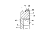
- FIG. 4 is a cross-sectional view taken along line AA ′ in FIG. 3
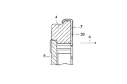
- FIG. 5 is a cross-sectional view taken along line BB ′ in FIG.
- the plate member 7 includes an outer ring locking portion 38, a main body portion 39, a penetrating portion 40, and an axial movement blocking portion 41.
- the main body 39 extends in the radial direction.
- the main body 39 is in contact with the other end face of the outer ring 4 in the axial direction.
- the penetrating portion 40 is connected to the main body portion 39.
- the penetrating portion 40 extends in the axial direction and penetrates the through hole 77 of the outer ring 4.
- the axial direction movement prevention part 41 is connected to the penetration part 40 and extends in the radial direction.
- the axial movement blocking portion 41 is in contact with the end surface 57 on one side of the power transmission member 6 in the axial direction.
- the outer ring 4 has an annular protrusion 54 on the outer peripheral surface of the other end in the axial direction.
- the outer ring locking portion 38 of the plate member 7 has an annular recess 53, and the shape of the annular recess 53 substantially corresponds to the shape of the annular protrusion 54.
- the plate member 7 is engaged and fixed to the outer ring 4.
- the outer peripheral surface of the power transmission member 6 is clearance-fitted to the inner peripheral surface of the outer ring 4 in the middle of the through portion 40 of the plate member 7 in the circumferential direction. It is fitted and fixed by fitting or interference fitting. Further, as shown in FIG.
- a step portion is provided inward in the radial direction of the outer ring 4, and a part of the axial end surface of the power transmission member 6 is provided on the end surface in the axial direction of the step portion of the outer ring 4.
- FIG. 6 is a perspective view showing a peripheral portion of the engaging roller 5 when the engaging roller 5 exists at the engaging position.
- the one-way clutch includes an urging device 50, and the urging device 50 includes a T-shaped portion 55, a spring stopper member 52, and a coil spring 10.
- the T-shaped portion 55 includes a stopper portion 51 and a rail portion 18.
- the T-shaped part 55 is a part of the plate member 7 and is formed by bending a part thereof.
- the spring retaining member 52 is made of a resin material.
- resin material glass fiber reinforced polyamide, polylactic acid bioplastic derived from plant raw materials, or the like can be used.
- the spring retaining member 52 can be slidably moved on the rail portion 18 by a structure described later.
- the coil spring 10 is wound around the cylindrical portion 58 of the spring stopper member 52.
- FIG. 7 is a view showing the T-shaped portion 55 of the plate member 7 before being bent.
- the T-shaped portion 55 is formed on a portion of the main body 39 (see FIGS. 4 and 5) of the plate member 7 that overlaps the engaging recess 15 (see FIG. 2) in the axial direction. linked.
- the T-shaped portion 55 in a state before being bent extends in the radial direction of the outer ring 4 (see FIG. 4).
- a portion extending in a substantially radial direction from the main body portion 39 constitutes a stopper portion 51. Further, the portion of the stopper portion 51 that extends from the central portion in the radial direction in a direction substantially perpendicular to the radial direction constitutes the rail portion 18.
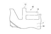
- FIG. 8 is a perspective view showing the T-shaped portion 55 in a state after being bent in the plate member 7.
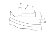
- FIG. 9 is a perspective view of the T-shaped portion 55 in a state after being bent in the plate member 7 from an angle different from that in FIG.
- the T-shaped portion 55 after bending is inclined substantially perpendicularly to the main body portion 39 of the plate member 7. Moreover, the T-shaped part 55 after bending extends in a direction substantially perpendicular to the radial direction.
- the stopper 51 extends substantially in the axial direction.
- reference numeral 38 indicates an outer ring locking portion (see FIG. 4) of the plate member 7.
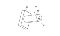
- FIG. 10 is a perspective view of the spring retaining member 52.
- the spring stop member 52 has a plate-like stopper portion 90 and a cylindrical portion 58.
- the cylindrical portion 58 extends from the end surface on one side of the stopper portion 90 in the axial direction in the normal direction of the end surface.
- the cylindrical portion 58 has a recess (notch) 92.
- the concave portion 92 has a plate shape and has a shape substantially corresponding to the shape of the rail portion 18. The size of the recess 92 is slightly larger than the rail portion 18 (see FIG. 9).
- the concave portion 92 passes through the central axis of the cylindrical portion 58.
- the concave portion 92 is opened in the radial direction at one place in the circumferential direction of the cylindrical portion 58.
- the rail portion 18 of the T-shaped portion 55 which is bent and raised is fitted into the concave portion 92 (see FIG. 10) of the cylindrical portion 58 of the spring stopper 52. .
- the spring stopper 52 can be slidably moved on the rail portion 18. It has become.
- the coil spring 10 is disposed radially outward of the cylindrical portion 58 and between the stopper portion 51 of the T-shaped portion 55 and the stopper portion 90 of the spring stopper member 52. Have been placed.
- the engagement roller 5 when the inner ring 3 rotates relative to the outer ring 4 in the direction indicated by the arrow C in FIG. 6, the engagement roller 5 has a radial interval in the engagement recess 15 as shown in FIG. 6. It is designed to bite into a narrow engagement position. The power between the inner and outer rings 3 and 4 is transmitted.
- the projecting fitting portion 30 of the power transmission member 6 is engaged with the engagement portion 35 of the engagement recess 15 of the outer ring 4 to transmit power to the outer ring 4. Since the member 6 is configured to be immovable in the circumferential direction, a bolt for fixing the power transmission member 6 to the outer ring 4 is not necessary, and the bolt necessary in the reference example can be omitted. Therefore, in comparison with the above reference example, the number of parts can be reduced and the manufacturing cost can be reduced.
- the protrusion fitting portion 30 of the power transmission member 6 is engaged with the engagement portion 35 of the engagement recess 15 of the outer ring 4, whereby the outer ring 4 is engaged. Since the power transmission member 6 is configured to be immovable in the circumferential direction, the tolerance of the runout accuracy with respect to the spigot diameter is absorbed in the tolerance of the runout accuracy of the inner diameter / outer diameter of the outer ring 4 and the cam groove in comparison with the reference example. can do. Therefore, in comparison with the one-way clutch of the reference example, the swing accuracy can be improved, power loss can be suppressed, and power can be transmitted smoothly.
- the movement-inhibiting engagement portion of the power transmission member 6 protrudes from the outer edge of the power transmission member 6 and fits into the engagement portion 35 of the engagement recess 15. Since it is the joint part 30, while being able to comprise the power transmission member 6 simply and compactly, the material cost of the power transmission member 6 can be reduced.
- the plate member 7 that closes the opening on the other side in the axial direction between the outer ring 4 and the inner ring 3 penetrates between the outer ring 4 and the inner ring 3 in the axial direction. Since it has the axial direction movement prevention part 41 extended along the end surface 57 of the axial direction one side of the power transmission member 6 from the penetration part 40, separation
- wheel 4 is prevented reliably. Can do.
- the through hole has a lid.
- the process of making a hole in the outer ring 4 and the process of press-fitting a plug into the hole can be eliminated, and the manufacturing cost and the number of processes can be reduced.
- the coil spring 10 is not positioned by the plug, and the position of the coil spring 10 does not depend on the position of the plug, so that the coil spring 10 can be positioned more accurately.
- the engagement element is the engagement roller 5.
- the engagement element may be an engagement element other than the engagement roller such as a sprag.
- the movement preventing engagement portion of the power transmission member 6 protrudes from the outer edge of the power transmission member 6 and fits into the engagement portion 35 of the engagement recess 15. 30.
- the movement preventing engagement portion of the power transmission member may be a protrusion protruding in the axial direction from one end surface in the axial direction of the disk-shaped main body portion of the power transmission member.
- the protrusion part protruding in the axial direction may be configured to engage with the engaging part of the engaging recess.
- rotational power is transmitted between the power transmission member 6 and the crankshaft 8 by spline fitting the power transmission member 6 and the crankshaft 8. It was.
- the power transmission member and the shaft member are rotated between the power transmission member and the shaft member by fitting other than the spline fitting, such as serration fitting or key fitting. Power transmission may be performed.
- the biasing member is the coil spring 10, but in this invention, the biasing member is generally employed as a biasing member for the one-way clutch such as a leaf spring. It may be an elastic member.
- the urging device 50 has a special configuration including the spring stopper member 52 and the T-shaped portion 55.
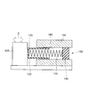
- the urging device is shown in the following diagram. The configuration as shown in FIG.
- the urging device 150 has a coil spring 110, a cylindrical guide member 120, and a plug 140, and the cylindrical guide member 120 has a lid 170 only on one side. Further, at least a part of the cylindrical guide member 120 and the coil spring 110 is accommodated in a through hole 180 formed in the outer ring 104, and the plug 140 is fixed in the through hole 180. Further, the lid portion 170 of the cylindrical guide member 120 is disposed so as to be able to contact the engaging roller 105, the coil spring 110 is disposed between the lid portion 170 and the plug 140, and the engaging roller 105 is moved by an arrow.
- the structure which can move to the direction shown by E may be sufficient.
- retainer may be sufficient as the one-way clutch of this invention.
- the urging device may have any configuration that is well known for a one-way clutch.
- the power transmission member cannot be moved in the circumferential direction with respect to the outer ring by engaging the movement preventing engagement part of the power transmission member with the engagement part of the engagement recess of the outer ring. Therefore, the bolt that fixes the power transmission member to the outer ring is not necessary, and the bolt that is necessary in the above reference example can be omitted. Therefore, in comparison with the above reference example, the number of parts can be reduced and the manufacturing cost can be reduced.
- the power transmission member by engaging the movement preventing engagement portion of the power transmission member with the engagement portion of the engagement recess of the outer ring, the power transmission member is moved in the circumferential direction with respect to the outer ring. Since it is configured to be non-movable, in comparison with the reference example, the tolerance of runout accuracy with respect to the spigot diameter can be absorbed in the tolerance of the runout accuracy of the inner diameter / outer diameter of the outer ring and the cam groove. Therefore, in comparison with the one-way clutch of the reference example, the swing accuracy can be improved, power loss can be suppressed, and power can be transmitted smoothly.
- the movement preventing engagement portion of the power transmission member may be a protruding fitting portion that protrudes from an outer edge of the power transmission member and engages with the engagement portion of the engagement recess.
- the movement preventing engagement portion of the power transmission member is a protruding fitting portion that protrudes from the outer edge of the power transmission member and fits into the engagement portion of the engagement recess, the power transmission member is simplified. In addition, it can be configured compactly, and the material cost of the power transmission member can be reduced.
- a plate member that closes at least a part of the opening on the other side in the axial direction between the outer ring and the inner ring;
- the plate member is A penetrating portion extending in the axial direction between the outer ring and the inner ring in the axial direction; and
- An axial movement blocking portion connected to the penetrating portion and extending along one axial end surface of the power transmission member to block movement of one side of the power transmission member in the axial direction; You may have.
- the plate member that closes the opening in the other axial direction between the outer ring and the inner ring is connected to the axial direction of the power transmission member from the penetrating portion that penetrates between the outer ring and the inner ring in the axial direction. Since it has the axial direction movement prevention part extended so that the end surface of a side may be followed, detachment
- the biasing member is a coil spring
- the plate member has a rod-shaped guide portion located in the engagement recess, The rod-shaped guide portion may be located inside the coil spring.
- the plug serving as a lid is fitted into the through hole.
- the process of making a hole in the outer ring and the process of press-fitting a plug into the hole can be eliminated, and the manufacturing cost and man-hours can be reduced.
- the coil spring is not positioned by the plug, and the position of the coil spring does not depend on the position of the plug. Therefore, the coil spring can be positioned more accurately.
- the movement preventing engagement portion of the power transmission member is engaged with the engagement portion of the engagement recess of the outer ring, and the power transmission member is circumferentially moved with respect to the outer ring. Therefore, the bolt for fixing the power transmission member to the outer ring can be omitted, the number of parts can be reduced, and the manufacturing cost can be reduced.
- the movement preventing engagement portion of the power transmission member is engaged with the engagement portion of the engagement recess of the outer ring so that the power transmission member is engaged with the outer ring. Since it is configured so as not to move in the circumferential direction, the tolerance of runout accuracy caused by fitting of the power transmission member to the outer ring can be absorbed by the tolerance of the runout accuracy of the inner diameter / outer diameter of the outer ring and the cam groove. Therefore, in comparison with the one-way clutch of the reference example, the swing accuracy can be improved, power loss can be suppressed, and power can be transmitted smoothly.
Landscapes
- Engineering & Computer Science (AREA)
- General Engineering & Computer Science (AREA)
- Mechanical Engineering (AREA)
- Mechanical Operated Clutches (AREA)
Abstract
L'invention porte sur un embrayage unidirectionnel dans lequel une cheville est éliminée et où la précision de la concentricité est améliorée. La surface périphérique interne d'une bague extérieure (4) a, formé dans cette surface, un évidement de prise qui présente une surface de prise de came et qui est ouvert à une extrémité dans la direction axiale. Une section d'ajustement saillante (30) d'un élément de transmission de force motrice (6), la section d'ajustement saillante (30) faisant saillie sur le bord extérieur de l'élément de transmission de force motrice (6), est en prise avec une section de prise (35) située dans l'évidement de prise, dans une position située sur un côté d'un élément de prise dans la direction axiale, et de cette façon l'élément de transmission de force motrice (6) est mis en prise avec la bague extérieure (4).
Applications Claiming Priority (2)
| Application Number | Priority Date | Filing Date | Title |
|---|---|---|---|
| JP2010032626A JP2011169373A (ja) | 2010-02-17 | 2010-02-17 | 一方向クラッチ |
| JP2010-032626 | 2010-02-17 |
Publications (1)
| Publication Number | Publication Date |
|---|---|
| WO2011102403A1 true WO2011102403A1 (fr) | 2011-08-25 |
Family
ID=44482989
Family Applications (1)
| Application Number | Title | Priority Date | Filing Date |
|---|---|---|---|
| PCT/JP2011/053333 Ceased WO2011102403A1 (fr) | 2010-02-17 | 2011-02-17 | Embrayage unidirectionnel |
Country Status (2)
| Country | Link |
|---|---|
| JP (1) | JP2011169373A (fr) |
| WO (1) | WO2011102403A1 (fr) |
Citations (6)
| Publication number | Priority date | Publication date | Assignee | Title |
|---|---|---|---|---|
| JPS4912506Y1 (fr) * | 1969-01-30 | 1974-03-27 | ||
| JPS50136562A (fr) * | 1974-04-05 | 1975-10-29 | ||
| JPH04110233U (ja) * | 1991-03-14 | 1992-09-24 | 光洋精工株式会社 | ワンウエイクラツチ |
| JPH11270594A (ja) * | 1998-03-19 | 1999-10-05 | Koyo Seiko Co Ltd | 一方向クラッチ |
| JP2007046618A (ja) * | 2005-08-05 | 2007-02-22 | Exedy Corp | 一方向クラッチ |
| JP2009138816A (ja) * | 2007-12-04 | 2009-06-25 | Exedy Corp | 一方向クラッチ |
-
2010
- 2010-02-17 JP JP2010032626A patent/JP2011169373A/ja active Pending
-
2011
- 2011-02-17 WO PCT/JP2011/053333 patent/WO2011102403A1/fr not_active Ceased
Patent Citations (6)
| Publication number | Priority date | Publication date | Assignee | Title |
|---|---|---|---|---|
| JPS4912506Y1 (fr) * | 1969-01-30 | 1974-03-27 | ||
| JPS50136562A (fr) * | 1974-04-05 | 1975-10-29 | ||
| JPH04110233U (ja) * | 1991-03-14 | 1992-09-24 | 光洋精工株式会社 | ワンウエイクラツチ |
| JPH11270594A (ja) * | 1998-03-19 | 1999-10-05 | Koyo Seiko Co Ltd | 一方向クラッチ |
| JP2007046618A (ja) * | 2005-08-05 | 2007-02-22 | Exedy Corp | 一方向クラッチ |
| JP2009138816A (ja) * | 2007-12-04 | 2009-06-25 | Exedy Corp | 一方向クラッチ |
Also Published As
| Publication number | Publication date |
|---|---|
| JP2011169373A (ja) | 2011-09-01 |
Similar Documents
| Publication | Publication Date | Title |
|---|---|---|
| EP3147526B1 (fr) | Embrayage à roue libre | |
| JP5037399B2 (ja) | ローラ型ワンウェイクラッチ | |
| CN107795605B (zh) | 棘轮式单向离合器 | |
| JP2009030790A (ja) | 一方向クラッチ | |
| TW201102543A (en) | Locking differential | |
| US9909628B2 (en) | Transmitter for a synchronising assembly of a manual transmission and a method for producing a transmitter | |
| US9765747B2 (en) | Starter return mechanism | |
| WO2011102403A1 (fr) | Embrayage unidirectionnel | |
| JP6128207B2 (ja) | 一方向クラッチ装置 | |
| WO2012077669A1 (fr) | Embrayage de blocage d'entrée inverse | |
| US10359083B2 (en) | Reverse input blocking clutch | |
| JP5586662B2 (ja) | 逆入力遮断機構 | |
| JP7141239B2 (ja) | ワンウェイクラッチ | |
| JP5544899B2 (ja) | 保持器アッセンブリおよび一方向クラッチ | |
| WO2012141087A1 (fr) | Accouplement à coupure de l'entrée inverse | |
| JP5602672B2 (ja) | 逆入力遮断機構 | |
| JP2010127349A (ja) | 逆入力防止クラッチ | |
| JP2007064348A (ja) | 一方向クラッチおよびクラッチ内蔵プーリ | |
| JP2009210025A (ja) | 逆入力防止クラッチ | |
| WO2014136828A1 (fr) | Embrayage à roue libre | |
| US20180266520A1 (en) | Shifting apparatus | |
| CN104895951B (zh) | 同步啮合装置 | |
| WO2020022043A1 (fr) | Embrayage et moteur | |
| JP6906581B2 (ja) | 逆入力遮断クラッチ | |
| JP2011256929A (ja) | 一方向クラッチ |
Legal Events
| Date | Code | Title | Description |
|---|---|---|---|
| 121 | Ep: the epo has been informed by wipo that ep was designated in this application |
Ref document number: 11744689 Country of ref document: EP Kind code of ref document: A1 |
|
| NENP | Non-entry into the national phase |
Ref country code: DE |
|
| 122 | Ep: pct application non-entry in european phase |
Ref document number: 11744689 Country of ref document: EP Kind code of ref document: A1 |