WO2011102403A1 - One-way clutch - Google Patents
One-way clutch Download PDFInfo
- Publication number
- WO2011102403A1 WO2011102403A1 PCT/JP2011/053333 JP2011053333W WO2011102403A1 WO 2011102403 A1 WO2011102403 A1 WO 2011102403A1 JP 2011053333 W JP2011053333 W JP 2011053333W WO 2011102403 A1 WO2011102403 A1 WO 2011102403A1
- Authority
- WO
- WIPO (PCT)
- Prior art keywords
- engagement
- outer ring
- power transmission
- axial direction
- way clutch
- Prior art date
- Legal status (The legal status is an assumption and is not a legal conclusion. Google has not performed a legal analysis and makes no representation as to the accuracy of the status listed.)
- Ceased
Links
Images


Classifications
-
- F—MECHANICAL ENGINEERING; LIGHTING; HEATING; WEAPONS; BLASTING
- F16—ENGINEERING ELEMENTS AND UNITS; GENERAL MEASURES FOR PRODUCING AND MAINTAINING EFFECTIVE FUNCTIONING OF MACHINES OR INSTALLATIONS; THERMAL INSULATION IN GENERAL
- F16D—COUPLINGS FOR TRANSMITTING ROTATION; CLUTCHES; BRAKES
- F16D41/00—Freewheels or freewheel clutches
- F16D41/06—Freewheels or freewheel clutches with intermediate wedging coupling members between an inner and an outer surface
- F16D41/064—Freewheels or freewheel clutches with intermediate wedging coupling members between an inner and an outer surface the intermediate members wedging by rolling and having a circular cross-section, e.g. balls
Definitions
- the present invention relates to a one-way clutch.
- the one-way clutch includes an outer ring, an inner ring, a plurality of engagement rollers, a coil spring, and a plurality of bolts.
- Each of the engagement rollers is disposed between the engagement cam surface of the outer ring and the engagement surface of the inner ring in a state of being biased in one direction by a coil spring.
- the plurality of engaging rollers are located at intervals in the circumferential direction.
- the outer ring has a plurality of bolt holes. After the bolts are inserted into the bolt holes of the outer ring, the outer ring is fixed to the crankshaft by tightening it on the end face of the crankshaft so that rotational power is transmitted between the outer ring and the crankshaft. Yes.
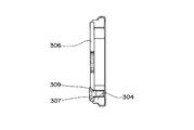
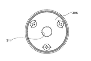
- an inlay portion 307 is provided on one end face in the axial direction of the outer ring 304, and a substantially disc-shaped power transmission member 306 is fitted into the inlay portion 307 by an inlay, and the outer ring There is a one-way clutch in which 304 and a power transmission member 306 are fixed by a plurality of bolts 309.
- a female spline 311 is formed at the center of the power transmission member 306, and a male spline formed on the outer peripheral surface of the crankshaft is spline-fitted to the female spline 311.
- a one-way clutch that transmits power between the outer ring 304 and the crankshaft.
- This one-way clutch has an advantage that power can be transmitted stably and smoothly because power is transmitted by spline fitting.
- the runout accuracy of the spline 311, the runout accuracy of the spigot diameter, and the runout accuracy of the inner ring / outer diameter / cam groove of the outer ring 304 affect the overall eccentricity, and it is difficult to increase the accuracy of the concentricity. is there.
- One of the objects of the present invention is to provide a one-way clutch capable of omitting the bolt and improving the accuracy of concentricity.
- An outer ring having an engagement cam surface and an engagement recess opening on one side in the axial direction on the inner peripheral surface;
- An inner ring having an engagement surface on the outer peripheral surface;
- An engagement element disposed between the engagement cam surface of the outer ring and the engagement surface of the inner ring;
- a biasing member that biases the engagement element in one direction;
- a power transmission member that closes at least a part of an opening on one side in the axial direction between the outer ring and the inner ring, and that transmits rotational power of the outer ring to a shaft member;
- the engaging recess has an engaging portion on one side in the axial direction of the engaging element,
- the power transmission member includes a movement prevention engagement portion that engages with the engagement portion of the engagement recess and prevents movement of the power transmission member in the circumferential direction with respect to the outer ring.
- the movement preventing engagement portion of the power transmission member is engaged with the engagement portion of the engagement recess of the outer ring, and the power transmission member is circumferentially moved with respect to the outer ring. Therefore, the bolt for fixing the power transmission member to the outer ring can be omitted, the number of parts can be reduced, and the manufacturing cost can be reduced.
- FIG. 4 is a sectional view taken along line AA ′ in FIG. 3.
- FIG. 4 is a sectional view taken along line BB ′ in FIG. 3.
- FIG. 1 is a schematic configuration diagram of a starter clutch which is an embodiment of the one-way clutch of the present invention.
- the starter clutch includes a starter motor 1, an idler gear 2, an inner ring 3, an outer ring 4, a plurality of engagement rollers 5 as an example of an engagement element, a plurality of coil springs as an example of an urging member, A transmission member 6 and a plate member 7 are provided.
- the power transmission member 6 is a disk-shaped member and closes an opening on one side in the axial direction between the inner ring 3 and the outer ring 4.
- the power transmission member 6 has a female spline at the center.
- the female spline of the power transmission member 6 is spline-fitted to a male spline formed on the outer peripheral surface of a crankshaft 8 as an example of a shaft member.
- the power transmission member 6 is not rotatable relative to the outer ring 4.
- the plate member 7 is a disk-like member and closes the opening on the other side in the axial direction between the inner ring 3 and the outer ring 4.
- This starter clutch transmits the rotational power of the starter motor 1 to the inner ring 3 engaged with the pinion of the idler gear 2 via the idler gear 2. Further, the rotational power transmitted to the inner ring 3 is transmitted to the outer ring 4 via the engaging rollers 5. Further, the rotational power transmitted to the outer ring 4 is transmitted to the crankshaft 8 via the power transmission member 6. In this way, the rotational power of the starter motor 1 is transmitted to the crankshaft 8.
- FIG. 2 shows the outer ring 4, the engaging roller 5, the coil spring 10 and the plate member 7 of the one-way clutch outside on the side opposite to the plate member 7 side in the axial direction (outward on one side in the axial direction). It is a figure when it sees from.
- the outer ring 4 has an engagement recess 15 on the inner peripheral surface, and the engagement recess 15 is open on one side and the other side in the axial direction. Further, the plate member 7 closes a portion overlapping the engagement roller 5 in the axial direction at the opening on the other axial side between the outer ring 4 and the inner ring 3 (see FIG. 1).
- the plate member 7 has a rail portion 18 as an example of a rod-shaped guide portion, and the rail portion 18 extends substantially parallel to the end surface 20 in the axial direction of the outer ring 4. ing.
- the rail portion 18 is located inside the coil spring 10.
- the coil spring 10 is constrained in the expansion / contraction direction by the rail portion 18.
- Each of the engaging rollers 5 is urged in one direction by a coil spring 10.
- the plate member 7 Before the power transmission member 6 (see FIG. 1) contacts the outer ring 4, the plate member 7 has a plate-like main body portion 39 and an axially extending portion 13.
- the main body 39 closes the opening on the other side in the axial direction between the inner ring 3 and the outer ring 4. Further, the axially extending portion 13 extends from the main body portion 39 in the axial direction.
- the axial dimension of the axially extending portion 13 is larger than the axial dimension of the outer ring 4.
- the axially extending portion 13 protrudes outward in the axial direction from the end surface 20 on one side of the outer ring 4 in the axial direction.
- FIG. 3 is a view of the state where the power transmission member 6 is engaged as viewed from the outside on one side in the axial direction. Specifically, FIG. 3 shows that the outer ring 4, the engagement roller 5, the coil spring 10, the power transmission member 6 and the plate member 7 of the one-way clutch are moved outwardly (in the axial direction) on the axial power transmission member 6 side. It is a figure when it sees from the outside of one side).
- the power transmission member 6 has a protruding fitting portion 30 that protrudes in the radial direction from the outer edge (outer peripheral surface) thereof, and the protruding fitting portion 30 includes the engaging recess 15 (see FIG. 2). ) Has a shape corresponding to the engaging portion 35 located on one side in the axial direction from the engaging roller 5. The protruding fitting portion 30 is fitted to the engaging portion 35.
- the power transmission member 6 is not movable in the circumferential direction with respect to the outer ring 4 by the fitting of the protruding fitting portion 30 and the engaging portion 35. In this way, the rotational power of the outer ring 4 is reliably transmitted to the power transmission member 6.
- the protrusion fitting portion 30 constitutes a movement preventing engagement portion.
- reference numeral 41 indicates a tip portion on one side in the axial direction of the axially extending portion 13 (see FIG. 2).
- the distal end portion 41 of the axially extending portion 13 extending in the axial direction is connected to the power transmission member. 6 is bent at a substantially right angle so as to be along the end face on one side in the axial direction. In this way, the axial movement of the power transmission member 6 is limited.
- the tip end portion 41 of the axially extending portion 13 constitutes an axial movement blocking portion of the plate member 7.
- the portion of the axially extending portion 13 that still extends in the axial direction penetrates between the outer ring 4 and the inner ring 3 (see FIG. 1) in the axial direction. ing.
- a portion of the axially extending portion 13 that still extends in the axial direction after the distal end portion 41 is bent constitutes a penetrating portion of the plate member 7.
- the tip portion (hereinafter referred to as “axial movement blocking portion”) 41 is positioned at a distance in the circumferential direction in the engagement recess 15 of the outer ring 4, and around the position where the engagement roller 5 exists. It is located at intervals in the direction.
- reference numeral 45 indicates a female spline of the power transmission member 6. As described above, the female spline 45 is spline-fitted with the male spline of the crankshaft 8 (see FIG. 1).
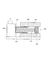
- FIG. 4 is a cross-sectional view taken along line AA ′ in FIG. 3
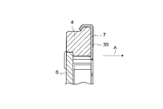
- FIG. 5 is a cross-sectional view taken along line BB ′ in FIG.
- the plate member 7 includes an outer ring locking portion 38, a main body portion 39, a penetrating portion 40, and an axial movement blocking portion 41.
- the main body 39 extends in the radial direction.
- the main body 39 is in contact with the other end face of the outer ring 4 in the axial direction.
- the penetrating portion 40 is connected to the main body portion 39.
- the penetrating portion 40 extends in the axial direction and penetrates the through hole 77 of the outer ring 4.
- the axial direction movement prevention part 41 is connected to the penetration part 40 and extends in the radial direction.
- the axial movement blocking portion 41 is in contact with the end surface 57 on one side of the power transmission member 6 in the axial direction.
- the outer ring 4 has an annular protrusion 54 on the outer peripheral surface of the other end in the axial direction.
- the outer ring locking portion 38 of the plate member 7 has an annular recess 53, and the shape of the annular recess 53 substantially corresponds to the shape of the annular protrusion 54.
- the plate member 7 is engaged and fixed to the outer ring 4.
- the outer peripheral surface of the power transmission member 6 is clearance-fitted to the inner peripheral surface of the outer ring 4 in the middle of the through portion 40 of the plate member 7 in the circumferential direction. It is fitted and fixed by fitting or interference fitting. Further, as shown in FIG.
- a step portion is provided inward in the radial direction of the outer ring 4, and a part of the axial end surface of the power transmission member 6 is provided on the end surface in the axial direction of the step portion of the outer ring 4.
- FIG. 6 is a perspective view showing a peripheral portion of the engaging roller 5 when the engaging roller 5 exists at the engaging position.
- the one-way clutch includes an urging device 50, and the urging device 50 includes a T-shaped portion 55, a spring stopper member 52, and a coil spring 10.
- the T-shaped portion 55 includes a stopper portion 51 and a rail portion 18.
- the T-shaped part 55 is a part of the plate member 7 and is formed by bending a part thereof.
- the spring retaining member 52 is made of a resin material.
- resin material glass fiber reinforced polyamide, polylactic acid bioplastic derived from plant raw materials, or the like can be used.
- the spring retaining member 52 can be slidably moved on the rail portion 18 by a structure described later.
- the coil spring 10 is wound around the cylindrical portion 58 of the spring stopper member 52.
- FIG. 7 is a view showing the T-shaped portion 55 of the plate member 7 before being bent.
- the T-shaped portion 55 is formed on a portion of the main body 39 (see FIGS. 4 and 5) of the plate member 7 that overlaps the engaging recess 15 (see FIG. 2) in the axial direction. linked.
- the T-shaped portion 55 in a state before being bent extends in the radial direction of the outer ring 4 (see FIG. 4).
- a portion extending in a substantially radial direction from the main body portion 39 constitutes a stopper portion 51. Further, the portion of the stopper portion 51 that extends from the central portion in the radial direction in a direction substantially perpendicular to the radial direction constitutes the rail portion 18.
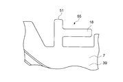
- FIG. 8 is a perspective view showing the T-shaped portion 55 in a state after being bent in the plate member 7.
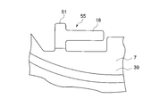
- FIG. 9 is a perspective view of the T-shaped portion 55 in a state after being bent in the plate member 7 from an angle different from that in FIG.
- the T-shaped portion 55 after bending is inclined substantially perpendicularly to the main body portion 39 of the plate member 7. Moreover, the T-shaped part 55 after bending extends in a direction substantially perpendicular to the radial direction.
- the stopper 51 extends substantially in the axial direction.
- reference numeral 38 indicates an outer ring locking portion (see FIG. 4) of the plate member 7.
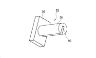
- FIG. 10 is a perspective view of the spring retaining member 52.
- the spring stop member 52 has a plate-like stopper portion 90 and a cylindrical portion 58.
- the cylindrical portion 58 extends from the end surface on one side of the stopper portion 90 in the axial direction in the normal direction of the end surface.
- the cylindrical portion 58 has a recess (notch) 92.
- the concave portion 92 has a plate shape and has a shape substantially corresponding to the shape of the rail portion 18. The size of the recess 92 is slightly larger than the rail portion 18 (see FIG. 9).
- the concave portion 92 passes through the central axis of the cylindrical portion 58.
- the concave portion 92 is opened in the radial direction at one place in the circumferential direction of the cylindrical portion 58.
- the rail portion 18 of the T-shaped portion 55 which is bent and raised is fitted into the concave portion 92 (see FIG. 10) of the cylindrical portion 58 of the spring stopper 52. .
- the spring stopper 52 can be slidably moved on the rail portion 18. It has become.
- the coil spring 10 is disposed radially outward of the cylindrical portion 58 and between the stopper portion 51 of the T-shaped portion 55 and the stopper portion 90 of the spring stopper member 52. Have been placed.
- the engagement roller 5 when the inner ring 3 rotates relative to the outer ring 4 in the direction indicated by the arrow C in FIG. 6, the engagement roller 5 has a radial interval in the engagement recess 15 as shown in FIG. 6. It is designed to bite into a narrow engagement position. The power between the inner and outer rings 3 and 4 is transmitted.
- the projecting fitting portion 30 of the power transmission member 6 is engaged with the engagement portion 35 of the engagement recess 15 of the outer ring 4 to transmit power to the outer ring 4. Since the member 6 is configured to be immovable in the circumferential direction, a bolt for fixing the power transmission member 6 to the outer ring 4 is not necessary, and the bolt necessary in the reference example can be omitted. Therefore, in comparison with the above reference example, the number of parts can be reduced and the manufacturing cost can be reduced.
- the protrusion fitting portion 30 of the power transmission member 6 is engaged with the engagement portion 35 of the engagement recess 15 of the outer ring 4, whereby the outer ring 4 is engaged. Since the power transmission member 6 is configured to be immovable in the circumferential direction, the tolerance of the runout accuracy with respect to the spigot diameter is absorbed in the tolerance of the runout accuracy of the inner diameter / outer diameter of the outer ring 4 and the cam groove in comparison with the reference example. can do. Therefore, in comparison with the one-way clutch of the reference example, the swing accuracy can be improved, power loss can be suppressed, and power can be transmitted smoothly.
- the movement-inhibiting engagement portion of the power transmission member 6 protrudes from the outer edge of the power transmission member 6 and fits into the engagement portion 35 of the engagement recess 15. Since it is the joint part 30, while being able to comprise the power transmission member 6 simply and compactly, the material cost of the power transmission member 6 can be reduced.
- the plate member 7 that closes the opening on the other side in the axial direction between the outer ring 4 and the inner ring 3 penetrates between the outer ring 4 and the inner ring 3 in the axial direction. Since it has the axial direction movement prevention part 41 extended along the end surface 57 of the axial direction one side of the power transmission member 6 from the penetration part 40, separation
- wheel 4 is prevented reliably. Can do.
- the through hole has a lid.
- the process of making a hole in the outer ring 4 and the process of press-fitting a plug into the hole can be eliminated, and the manufacturing cost and the number of processes can be reduced.
- the coil spring 10 is not positioned by the plug, and the position of the coil spring 10 does not depend on the position of the plug, so that the coil spring 10 can be positioned more accurately.
- the engagement element is the engagement roller 5.
- the engagement element may be an engagement element other than the engagement roller such as a sprag.
- the movement preventing engagement portion of the power transmission member 6 protrudes from the outer edge of the power transmission member 6 and fits into the engagement portion 35 of the engagement recess 15. 30.
- the movement preventing engagement portion of the power transmission member may be a protrusion protruding in the axial direction from one end surface in the axial direction of the disk-shaped main body portion of the power transmission member.
- the protrusion part protruding in the axial direction may be configured to engage with the engaging part of the engaging recess.
- rotational power is transmitted between the power transmission member 6 and the crankshaft 8 by spline fitting the power transmission member 6 and the crankshaft 8. It was.
- the power transmission member and the shaft member are rotated between the power transmission member and the shaft member by fitting other than the spline fitting, such as serration fitting or key fitting. Power transmission may be performed.
- the biasing member is the coil spring 10, but in this invention, the biasing member is generally employed as a biasing member for the one-way clutch such as a leaf spring. It may be an elastic member.
- the urging device 50 has a special configuration including the spring stopper member 52 and the T-shaped portion 55.
- the urging device is shown in the following diagram. The configuration as shown in FIG.
- the urging device 150 has a coil spring 110, a cylindrical guide member 120, and a plug 140, and the cylindrical guide member 120 has a lid 170 only on one side. Further, at least a part of the cylindrical guide member 120 and the coil spring 110 is accommodated in a through hole 180 formed in the outer ring 104, and the plug 140 is fixed in the through hole 180. Further, the lid portion 170 of the cylindrical guide member 120 is disposed so as to be able to contact the engaging roller 105, the coil spring 110 is disposed between the lid portion 170 and the plug 140, and the engaging roller 105 is moved by an arrow.
- the structure which can move to the direction shown by E may be sufficient.
- retainer may be sufficient as the one-way clutch of this invention.
- the urging device may have any configuration that is well known for a one-way clutch.
- the power transmission member cannot be moved in the circumferential direction with respect to the outer ring by engaging the movement preventing engagement part of the power transmission member with the engagement part of the engagement recess of the outer ring. Therefore, the bolt that fixes the power transmission member to the outer ring is not necessary, and the bolt that is necessary in the above reference example can be omitted. Therefore, in comparison with the above reference example, the number of parts can be reduced and the manufacturing cost can be reduced.
- the power transmission member by engaging the movement preventing engagement portion of the power transmission member with the engagement portion of the engagement recess of the outer ring, the power transmission member is moved in the circumferential direction with respect to the outer ring. Since it is configured to be non-movable, in comparison with the reference example, the tolerance of runout accuracy with respect to the spigot diameter can be absorbed in the tolerance of the runout accuracy of the inner diameter / outer diameter of the outer ring and the cam groove. Therefore, in comparison with the one-way clutch of the reference example, the swing accuracy can be improved, power loss can be suppressed, and power can be transmitted smoothly.
- the movement preventing engagement portion of the power transmission member may be a protruding fitting portion that protrudes from an outer edge of the power transmission member and engages with the engagement portion of the engagement recess.
- the movement preventing engagement portion of the power transmission member is a protruding fitting portion that protrudes from the outer edge of the power transmission member and fits into the engagement portion of the engagement recess, the power transmission member is simplified. In addition, it can be configured compactly, and the material cost of the power transmission member can be reduced.
- a plate member that closes at least a part of the opening on the other side in the axial direction between the outer ring and the inner ring;
- the plate member is A penetrating portion extending in the axial direction between the outer ring and the inner ring in the axial direction; and
- An axial movement blocking portion connected to the penetrating portion and extending along one axial end surface of the power transmission member to block movement of one side of the power transmission member in the axial direction; You may have.
- the plate member that closes the opening in the other axial direction between the outer ring and the inner ring is connected to the axial direction of the power transmission member from the penetrating portion that penetrates between the outer ring and the inner ring in the axial direction. Since it has the axial direction movement prevention part extended so that the end surface of a side may be followed, detachment
- the biasing member is a coil spring
- the plate member has a rod-shaped guide portion located in the engagement recess, The rod-shaped guide portion may be located inside the coil spring.
- the plug serving as a lid is fitted into the through hole.
- the process of making a hole in the outer ring and the process of press-fitting a plug into the hole can be eliminated, and the manufacturing cost and man-hours can be reduced.
- the coil spring is not positioned by the plug, and the position of the coil spring does not depend on the position of the plug. Therefore, the coil spring can be positioned more accurately.
- the movement preventing engagement portion of the power transmission member is engaged with the engagement portion of the engagement recess of the outer ring, and the power transmission member is circumferentially moved with respect to the outer ring. Therefore, the bolt for fixing the power transmission member to the outer ring can be omitted, the number of parts can be reduced, and the manufacturing cost can be reduced.
- the movement preventing engagement portion of the power transmission member is engaged with the engagement portion of the engagement recess of the outer ring so that the power transmission member is engaged with the outer ring. Since it is configured so as not to move in the circumferential direction, the tolerance of runout accuracy caused by fitting of the power transmission member to the outer ring can be absorbed by the tolerance of the runout accuracy of the inner diameter / outer diameter of the outer ring and the cam groove. Therefore, in comparison with the one-way clutch of the reference example, the swing accuracy can be improved, power loss can be suppressed, and power can be transmitted smoothly.
Landscapes
- Engineering & Computer Science (AREA)
- General Engineering & Computer Science (AREA)
- Mechanical Engineering (AREA)
- Mechanical Operated Clutches (AREA)
Abstract
Description
本発明は、一方向クラッチに関する。 The present invention relates to a one-way clutch.
従来、一方向クラッチとしては、特開2004-346951号公報(特許文献1)に記載されているものがある。この一方向クラッチは、外輪と、内輪と、複数の係合ころと、コイルばねと、複数のボルトとを備える。上記各係合ころは、外輪の係合カム面と、内輪の係合面との間に、コイルばねで一方向に付勢された状態で、配置されている。上記複数の係合ころは、周方向に互いに間隔をおいて位置している。 Conventionally, as a one-way clutch, there is one described in Japanese Patent Application Laid-Open No. 2004-346951 (Patent Document 1). The one-way clutch includes an outer ring, an inner ring, a plurality of engagement rollers, a coil spring, and a plurality of bolts. Each of the engagement rollers is disposed between the engagement cam surface of the outer ring and the engagement surface of the inner ring in a state of being biased in one direction by a coil spring. The plurality of engaging rollers are located at intervals in the circumferential direction.
上記外輪は、複数のボルト孔を有している。上記各ボルトを、外輪のボルト孔に挿通した後、クランクシャフトの端面に締め付けることにより、外輪を、クランクシャフトに固定し、外輪と、クランクシャフトとの間で、回転動力を伝達するようにしている。 The outer ring has a plurality of bolt holes. After the bolts are inserted into the bolt holes of the outer ring, the outer ring is fixed to the crankshaft by tightening it on the end face of the crankshaft so that rotational power is transmitted between the outer ring and the crankshaft. Yes.
上記従来の一方向クラッチは、ボルトによって回転動力の伝達が行われるため、ボルトに絶え間なく大きなトルクが作用して、ボルトが劣化し易く、最悪の場合、ボルト折れが発生する可能性がある。 In the conventional one-way clutch, since rotational power is transmitted by the bolt, a large torque is constantly applied to the bolt, and the bolt is likely to deteriorate. In the worst case, the bolt may be broken.
上記問題を回避できる一方向クラッチとしては、以下の図13、図14に示す参考例の一方向クラッチ(この参考例の一方向クラッチは、本願の出願時に公知ではない。この参考例の一方向クラッチは、新規性を失っていない。)がある。 As a one-way clutch that can avoid the above problem, the one-way clutch shown in the following reference examples shown in FIGS. 13 and 14 (the one-way clutch of this reference example is not known at the time of filing this application. Clutch has not lost novelty.)
詳しくは、図13に示すように、外輪304の軸方向の一方側の端面にインロー部307を設け、そのインロー部307に、略円板状の動力伝達部材306をインロー嵌合すると共に、外輪304と、動力伝達部材306とを複数のボルト309で固定した一方向クラッチがある。
Specifically, as shown in FIG. 13, an
また、図14に示すように、上記動力伝達部材306の中央部に、雌のスプライン311を形成し、この雌のスプライン311に、クランクシャフトの外周面に形成した雄のスプラインをスプライン嵌合して、外輪304と、クランクシャフトとの間を、動力伝達する一方向クラッチがある。
Further, as shown in FIG. 14, a
この一方向クラッチは、スプライン嵌合により、動力伝達を行うので、動力の伝達を安定かつ円滑に行うことができるという利点を有する。 This one-way clutch has an advantage that power can be transmitted stably and smoothly because power is transmitted by spline fitting.
しかし、この参考例の一方向クラッチでは、複数のボルト309が必要不可欠であって、製造コストが大きいという課題がある。
However, in the one-way clutch of this reference example, a plurality of
また、スプライン311の振れ精度、インロー径の振れ精度および外輪304の内径・外径・カム溝の振れ精度が、全体の偏心量に影響し、同心度の精度を高くするのが難しいという課題がある。
Further, the runout accuracy of the
本発明の目的のひとつは、ボルトを省略できると共に、同心度の精度を向上できる一方向クラッチを提供することにある。 One of the objects of the present invention is to provide a one-way clutch capable of omitting the bolt and improving the accuracy of concentricity.
この発明の一方向クラッチの一実施形態においては、
係合カム面を有すると共に、軸方向の一方側が開口する係合凹部を内周面に有する外輪と、
係合面を外周面に有する内輪と、
上記外輪の係合カム面と、上記内輪の係合面との間に配置された係合子と、
上記係合子を一方向に付勢する付勢部材と、
上記外輪と上記内輪との間の軸方向の一方側の開口の少なくとも一部を塞ぐと共に、上記外輪の回転動力を軸部材に伝達する動力伝達部材と
を備え、
上記係合凹部は、上記係合子の軸方向の一方側に係合部を有し、
上記動力伝達部材は、上記係合凹部の上記係合部に係合して、上記外輪に対する上記動力伝達部材の周方向の移動を阻止する移動阻止係合部を有することを特徴としている。
In one embodiment of the one-way clutch of the present invention,
An outer ring having an engagement cam surface and an engagement recess opening on one side in the axial direction on the inner peripheral surface;
An inner ring having an engagement surface on the outer peripheral surface;
An engagement element disposed between the engagement cam surface of the outer ring and the engagement surface of the inner ring;
A biasing member that biases the engagement element in one direction;
A power transmission member that closes at least a part of an opening on one side in the axial direction between the outer ring and the inner ring, and that transmits rotational power of the outer ring to a shaft member;
The engaging recess has an engaging portion on one side in the axial direction of the engaging element,
The power transmission member includes a movement prevention engagement portion that engages with the engagement portion of the engagement recess and prevents movement of the power transmission member in the circumferential direction with respect to the outer ring.
本発明の実施形態に係る一方向クラッチによれば、動力伝達部材の移動阻止係合部を、外輪の係合凹部の係合部に係合させて、外輪に対して動力伝達部材を周方向に移動不可にする構成であるから、外輪に対して動力伝達部材を固定するボルトを省略できて、部品点数を低減でき、製造コストを低減できる。 According to the one-way clutch according to the embodiment of the present invention, the movement preventing engagement portion of the power transmission member is engaged with the engagement portion of the engagement recess of the outer ring, and the power transmission member is circumferentially moved with respect to the outer ring. Therefore, the bolt for fixing the power transmission member to the outer ring can be omitted, the number of parts can be reduced, and the manufacturing cost can be reduced.
以下、本発明を図示の形態により詳細に説明する。 Hereinafter, the present invention will be described in detail with reference to the drawings.
図1は、本発明の一方向クラッチの一実施形態であるスタータクラッチの概略構成図である。 FIG. 1 is a schematic configuration diagram of a starter clutch which is an embodiment of the one-way clutch of the present invention.
このスタータクラッチは、スタータモータ1と、アイドラギヤ2と、内輪3と、外輪4と、係合子の一例としての複数の係合ころ5と、付勢部材の一例としての複数のコイルばねと、動力伝達部材6と、板部材7とを備える。
The starter clutch includes a
上記動力伝達部材6は、円板状の部材であり、内輪3と外輪4との間の軸方向の一方側の開口を塞いでいる。上記動力伝達部材6は、その中央部に雌のスプラインを有している。
The
上記動力伝達部材6の雌のスプラインは、軸部材の一例としてのクランク軸8の外周面に形成された雄のスプラインにスプライン嵌合している。後に詳述するが、上記動力伝達部材6は、外輪4に対して相対回転不可になっている。一方、上記板部材7は、円板状の部材であり、内輪3と外輪4との間の軸方向の他方側の開口を塞いでいる。
The female spline of the
このスタータクラッチは、スタータモータ1の回転動力を、アイドラギヤ2を介して、アイドラギヤ2にピニオン噛合している内輪3に伝達している。また、上記内輪3に伝達された回転動力を、係合ころ5を介して外輪4に伝達するようになっている。また、外輪4に伝達された回転動力を、動力伝達部材6を介して、クランク軸8に伝達するようになっている。このようにして、上記スタータモータ1の回転動力を、クランク軸8に伝達するようになっている。
This starter clutch transmits the rotational power of the
図2は、上記一方向クラッチの、外輪4、係合ころ5、コイルばね10および板部材7を、軸方向の板部材7側とは反対側の外方(軸方向の一方側の外方)から見たときの図である。
FIG. 2 shows the
図2に示すように、上記外輪4は、係合凹部15を内周面に有し、その係合凹部15は、軸方向の一方側および他方側に開口している。また、上記板部材7は、外輪4と内輪3(図1参照)との間の軸方向の他方側の開口において、係合ころ5に軸方向に重なる部分を塞いでいる。
As shown in FIG. 2, the
また、後に詳述するが、上記板部材7は、棒状のガイド部の一例としてのレール部18を有し、そのレール部18は、外輪4の軸方向の端面20に略平行に延在している。上記レール部18は、コイルばね10の内部に位置している。上記コイルばね10は、レール部18によって伸縮方向を拘束されている。上記各係合ころ5は、コイルばね10によって一方向に付勢されている。
As will be described in detail later, the
上記動力伝達部材6(図1参照)が外輪4に接触する前において、板部材7は、平板状の本体部39と、軸方向延在部13とを有している。上記本体部39は、内輪3と外輪4との間の軸方向の他方側の開口を塞いでいる。また、上記軸方向延在部13は、本体部39から軸方向に延在している。上記軸方向延在部13の軸方向の寸法は、外輪4の軸方向の寸法よりも大きくなっている。上記軸方向延在部13は、外輪4の軸方向の一方側の端面20よりも軸方向の外方に突出している。
Before the power transmission member 6 (see FIG. 1) contacts the
図3は、動力伝達部材6を係合した状態を、軸方向の一方側の外方から見たときの図である。詳しくは、図3は、上記一方向クラッチの、外輪4、係合ころ5、コイルばね10、動力伝達部材6および板部材7を、軸方向の動力伝達部材6側の外方(軸方向の一方側の外方)から見たときの図である。
FIG. 3 is a view of the state where the
図3に示すように、上記動力伝達部材6は、その外縁(外周面)から径方向に突出する突出嵌合部30を有し、突出嵌合部30は、係合凹部15(図2参照)において係合ころ5よりも軸方向の一方側に位置する係合部35に対応する形状を有している。上記突出嵌合部30は、係合部35に嵌合している。上記突出嵌合部30と、係合部35との嵌合によって、動力伝達部材6が外輪4に対して周方向に移動不可になっている。このようにして、外輪4の回転動力を、動力伝達部材6に確実に伝達している。上記突出嵌合部30は、移動阻止係合部を構成している。
As shown in FIG. 3, the
図3において、参照番号41は、上記軸方向延在部13(図2参照)の軸方向の一方側の先端部を示している。上記外輪4の係合部35と、動力伝達部材6の突出嵌合部30とを嵌合した後、軸方向に延在している軸方向延在部13の先端部41を、動力伝達部材6の軸方向の一方側の端面に沿うように、略直角に折り曲げる。このようにして、動力伝達部材6の軸方向の動きを制限するようにしている。上記軸方向延在部13の先端部41は、板部材7の軸方向移動阻止部を構成している。
3,
また、上記先端部41の折り曲げ後、軸方向延在部13のうちで依然として軸方向に延在している部分は、外輪4と内輪3(図1参照)との間を軸方向に貫通している。上記先端部41の折り曲げ後、軸方向延在部13のうちで依然として軸方向に延在している部分は、板部材7の貫通部を構成している。図3に示すように、上記先端部(以下、軸方向移動阻止部という)41は、外輪4の係合凹部15に周方向に間隔をおいて位置し、係合ころ5の存在位置に周方向に間隔をおいて位置している。
In addition, after the
尚、図3において、参照番号45は、動力伝達部材6の雌のスプラインを示している。上述のように、この雌のスプライン45は、クランク軸8(図1参照)の雄のスプラインと、スプライン嵌合している。
In FIG. 3,
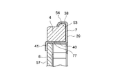
図4は、図3のAA'線断面図であり、図5は、図3のBB'線断面図である。 4 is a cross-sectional view taken along line AA ′ in FIG. 3, and FIG. 5 is a cross-sectional view taken along line BB ′ in FIG.
図4に示すように、上記板部材7は、外輪係止部38と、本体部39と、貫通部40と、軸方向移動阻止部41とを有する。上記本体部39は、径方向に広がっている。上記本体部39は、外輪4の軸方向の他方側の端面に当接している。上記貫通部40は、本体部39につながっている。上記貫通部40は、軸方向に延在すると共に、外輪4の貫通穴77を貫通している。
As shown in FIG. 4, the
上記軸方向移動阻止部41は、貫通部40につながると共に、径方向に延在している。上記軸方向移動阻止部41は、動力伝達部材6の軸方向の一方側の端面57に当接している。
The axial direction
上記外輪4は、軸方向の他方側の端部の外周面に環状突出部54を有している。上記板部材7の外輪係止部38は、環状凹部53を有し、環状凹部53の形状は、環状突出部54の形状に略対応している。上記環状凹部53を、外輪4の環状突出部54に嵌合することにより、板部材7を外輪4に係合して固定している。また、図5を参照して、上記板部材7の貫通部40に周方向に間隔をおいている部分では、動力伝達部材6の外周面は、外輪4の内周面に、すきま嵌め、中間嵌め、または、締まり嵌めにより、内嵌されて固定されている。また、図5に示すように、上記外輪4の径方向の内方に段部を設け、その外輪4の段部の軸方向の端面に、動力伝達部材6の軸方向の端面の一部を当接することにより、動力伝達部材6のA方向への軸方向の移動を拘束している。
The
図6は、係合ころ5が係合位置に存在しているときの、係合ころ5の周辺部を示す斜視図である。
FIG. 6 is a perspective view showing a peripheral portion of the engaging
図6に示すように、この一方向クラッチは、付勢装置50を有し、付勢装置50は、T字状部55と、ばね止め部材52と、コイルばね10とを有する。また、上記T字状部55は、ストッパ部51と、レール部18とを有する。上記T字状部55は、板部材7の一部分であり、その一部分を折り曲げて起こして形成されている。
As shown in FIG. 6, the one-way clutch includes an urging
上記ばね止め部材52は、樹脂材料からなっている。ここで、樹脂材料としては、ガラス繊維強化型ポリアミドや、植物原料由来のポリ乳酸バイオプラスチック等を利用できる。上記ばね止め部材52は、後述する構造により、レール部18上を摺動自在に移動できるようになっている。また、上記コイルばね10は、ばね止め部材52の円筒状部58上に巻き付けられている。
The
図7は、板部材7において折り曲げ前の状態のT字状部55を示す図である。
FIG. 7 is a view showing the T-shaped
図7に示すように、上記T字状部55は、板部材7の本体部39(図4、図5参照)において軸方向に係合凹部15(図2参照)に重なっている部分に、つながっている。折り曲げ前の状態のT字状部55は、外輪4(図4参照)の径方向に延在している。
As shown in FIG. 7, the T-shaped
折り曲げ前の状態のT字状部55において、本体部39から略径方向に延在している部分は、ストッパ部51を構成している。また、上記ストッパ部51の径方向の中央部から径方向に略垂直な方向に延在している部分は、レール部18を構成している。
In the T-shaped
図8は、板部材7において折り曲げ後の状態のT字状部55を示す斜視図である。また、図9は、図8とは違った角度から板部材7において折り曲げ後の状態のT字状部55を見たときの斜視図である。
FIG. 8 is a perspective view showing the T-shaped
図8および図9に示すように、折り曲げ後のT字状部55は、板部材7の本体部39に対して略垂直に傾いている。また、折り曲げ後のT字状部55は、径方向に略垂直な方向に延在している。また、上記ストッパ部51は、略軸方向に延在している。尚、図9において、参照番号38は、板部材7の外輪係止部(図4参照)を示している。
As shown in FIGS. 8 and 9, the T-shaped
図10は、上記ばね止め部材52の斜視図である。
FIG. 10 is a perspective view of the
図10に示すように、上記ばね止め部材52は、板状のストッパ部90と、円筒状部58とを有する。上記円筒状部58は、ストッパ部90の軸方向の一方側の端面からその端面の法線方向に延在している。上記円筒状部58は、凹部(切り込み)92を有する。上記凹部92は、板状の形状を有し、レール部18の形状に略対応する形状を有する。上記凹部92の大きさは、レール部18(図9参照)よりも若干大きくなっている。上記凹部92は、円筒状部58の中心軸を通過している。上記凹部92は、円筒状部58の周方向の一箇所において径方向に開口している。
As shown in FIG. 10, the
再度、図6を参照して、上記ばね止め部材52の円筒状部58の凹部92(図10参照)に、折り曲げられて起こされたT字状部55のレール部18を嵌合している。上述のように、上記凹部92の大きさが、レール部18(図9参照)よりも若干大きくなっていることにより、ばね止め部材52が、レール部18上を摺動自在に移動できるようになっている。また、図6に示すように、コイルばね10が、円筒状部58の径方向の外方、かつ、T字状部55のストッパ部51と、ばね止め部材52のストッパ部90との間に、配置されている。
Referring to FIG. 6 again, the
上記構成において、上記内輪3が、外輪4に対して図6に矢印Cで示す方向に相対回転すると、図6に示すように、係合ころ5が、係合凹部15において径方向の間隔が狭い係合位置に噛み込むようになっている。そして、内外輪3,4の間の動力を伝達するようになっている。
In the above configuration, when the
一方、上記内輪3が、外輪4に対して、図11に、矢印Dで示す方向に相対回転すると、図11に示すように、係合ころ5が、係合凹部15において径方向の間隔が大きい遊嵌位置に移動するようになっている。そして、内外輪3,4の間の動力が遮断されるようになっている。
On the other hand, when the
上記実施形態の一方向クラッチによれば、上記動力伝達部材6の突出嵌合部30を、外輪4の係合凹部15の係合部35に係合させることにより、外輪4に対して動力伝達部材6を周方向に移動不可にする構成であるから、外輪4に対して動力伝達部材6を固定するボルトが必要でなく、上記参考例で必要であったボルトを省略できる。したがって、上記参考例との比較において、部品点数を低減できて、製造コストを低減できる。
According to the one-way clutch of the above embodiment, the projecting
また、上記実施形態の一方向クラッチによれば、上記動力伝達部材6の突出嵌合部30を、外輪4の係合凹部15の係合部35に係合させることにより、外輪4に対して動力伝達部材6を周方向に移動不可にする構成であるから、参考例との比較において、インロー径に対する振れ精度の公差を、外輪4の内径・外径・カム溝の振れ精度の公差に吸収することができる。したがって、参考例の一方向クラッチとの比較において、振れ精度を向上することができて、動力損失を抑制でき、動力の伝達を円滑に行うことができる。
Further, according to the one-way clutch of the above-described embodiment, the
また、上記実施形態の一方向クラッチによれば、上記動力伝達部材6の移動阻止係合部が、動力伝達部材6の外縁から突出して係合凹部15の係合部35に嵌合する突出嵌合部30であるから、動力伝達部材6をシンプルかつコンパクトに構成できると共に、動力伝達部材6の材料コストを低減できる。
Further, according to the one-way clutch of the above-described embodiment, the movement-inhibiting engagement portion of the
また、上記実施形態の一方向クラッチによれば、外輪4と内輪3との間の軸方向の他方側の開口を塞ぐ板部材7が、外輪4と内輪3との間を軸方向に貫通する貫通部40から動力伝達部材6の軸方向の一方側の端面57に沿うように延在する軸方向移動阻止部41を有するから、外輪4からの動力伝達部材6の離脱を確実に防止することができる。
Further, according to the one-way clutch of the above embodiment, the
また、上記実施形態の一方向クラッチによれば、従来と異なり、外輪4にコイルばね10を挿入するために、貫通穴を形成する必要がなく、また、従来と異なり、その貫通穴に蓋の役目を担うプラグを嵌合する必要もない。したがって、外輪4に穴を空ける工程と、穴にプラグを圧入する工程を廃止することができて、製造コストおよび工数を低減できる。また、従来と異なり、コイルばね10の位置決めをプラグで行う構成でなくて、コイルばね10の位置がプラグの位置に依存しないから、コイルばね10の位置決めをより正確に行うことができる。
In addition, according to the one-way clutch of the above embodiment, unlike the conventional case, there is no need to form a through hole in order to insert the
尚、上記実施形態の一方向クラッチでは、係合子が、係合ころ5であったが、この発明では、係合子は、スプラグ等の係合ころ以外の係合子であっても良い。
In the one-way clutch of the above embodiment, the engagement element is the
また、上記実施形態の一方向クラッチでは、上記動力伝達部材6の移動阻止係合部が、動力伝達部材6の外縁から突出して係合凹部15の係合部35に嵌合する突出嵌合部30であった。しかしながら、この発明では、動力伝達部材の移動阻止係合部は、動力伝達部材の円板状の本体部の軸方向の一方側の端面から軸方向に突出する突起部であっても良く、この軸方向に突出する突起部を、係合凹部の係合部に係合させる構成であっても良い。
Further, in the one-way clutch of the embodiment, the movement preventing engagement portion of the
また、上記実施形態の一方向クラッチでは、動力伝達部材6と、クランク軸8とを、スプライン嵌合することにより、動力伝達部材6と、クランク軸8との間で、回転動力の伝達を行った。しかしながら、この発明では、動力伝達部材と、軸部材とを、セレーション嵌合またはキー嵌合等、スプライン嵌合以外の嵌合をすることにより、動力伝達部材と、軸部材との間で、回転動力の伝達を行っても良い。
In the one-way clutch of the above-described embodiment, rotational power is transmitted between the
また、上記実施形態の一方向クラッチでは、付勢部材が、コイルばね10であったが、この発明では、付勢部材は、板ばね等、一方向クラッチの付勢部材として、一般的に採用される弾性部材であっても良い。
In the one-way clutch of the above embodiment, the biasing member is the
また、上記実施形態の一方向クラッチでは、付勢装置50が、ばね止め部材52や、T字状部55を有する特殊な構成であったが、この発明では、付勢装置は、以下の図12に示すような構成であっても良い。
In the one-way clutch of the above-described embodiment, the urging
すなわち、付勢装置150は、コイルばね110、円筒状ガイド部材120、および、プラグ140を有し、円筒状ガイド部材120は、一方側のみに蓋部170を有する。また、上記円筒状ガイド部材120およびコイルばね110の少なくとも一部が、外輪104に形成された貫通穴180に収容され、プラグ140が貫通穴180内に固定される。また、上記円筒状ガイド部材120の蓋部170が、係合ころ105に接触可能に配置され、コイルばね110が、蓋部170とプラグ140との間に配置され、係合ころ105が、矢印Eで示す方向に移動可能である構成であっても良い。また、この発明の一方クラッチは、保持器の柱部から付勢部材の一方側の反力を得る構成であっても良い。また、この発明では、付勢装置は、一方向クラッチで周知である如何なる構成であっても良い。
That is, the urging
本発明の一実施形態によれば、動力伝達部材の移動阻止係合部を、外輪の係合凹部の係合部に係合させることにより、外輪に対して動力伝達部材を周方向に移動不可にする構成であるから、外輪に対して動力伝達部材を固定するボルトが必要でなく、上記参考例で必要であったボルトを省略できる。したがって、上記参考例との比較において、部品点数を低減できて、製造コストを低減できる。 According to one embodiment of the present invention, the power transmission member cannot be moved in the circumferential direction with respect to the outer ring by engaging the movement preventing engagement part of the power transmission member with the engagement part of the engagement recess of the outer ring. Therefore, the bolt that fixes the power transmission member to the outer ring is not necessary, and the bolt that is necessary in the above reference example can be omitted. Therefore, in comparison with the above reference example, the number of parts can be reduced and the manufacturing cost can be reduced.
また、本発明の一実施形態によれば、動力伝達部材の移動阻止係合部を、外輪の係合凹部の係合部に係合させることにより、外輪に対して動力伝達部材を周方向に移動不可にする構成であるから、参考例との比較において、インロー径に対する振れ精度の公差を、外輪の内径・外径・カム溝の振れ精度の公差に吸収することができる。したがって、参考例の一方向クラッチとの比較において、振れ精度を向上することができて、動力損失を抑制でき、動力の伝達を円滑に行うことができる。 Further, according to one embodiment of the present invention, by engaging the movement preventing engagement portion of the power transmission member with the engagement portion of the engagement recess of the outer ring, the power transmission member is moved in the circumferential direction with respect to the outer ring. Since it is configured to be non-movable, in comparison with the reference example, the tolerance of runout accuracy with respect to the spigot diameter can be absorbed in the tolerance of the runout accuracy of the inner diameter / outer diameter of the outer ring and the cam groove. Therefore, in comparison with the one-way clutch of the reference example, the swing accuracy can be improved, power loss can be suppressed, and power can be transmitted smoothly.
また、他の実施形態として、
上記動力伝達部材の上記移動阻止係合部は、上記動力伝達部材の外縁から突出して上記係合凹部の上記係合部に嵌合する突出嵌合部であってもよい。
As another embodiment,
The movement preventing engagement portion of the power transmission member may be a protruding fitting portion that protrudes from an outer edge of the power transmission member and engages with the engagement portion of the engagement recess.
上記実施形態によれば、動力伝達部材の移動阻止係合部が、動力伝達部材の外縁から突出して係合凹部の係合部に嵌合する突出嵌合部であるから、動力伝達部材をシンプルかつコンパクトに構成できると共に、動力伝達部材の材料コストを低減できる。 According to the above embodiment, since the movement preventing engagement portion of the power transmission member is a protruding fitting portion that protrudes from the outer edge of the power transmission member and fits into the engagement portion of the engagement recess, the power transmission member is simplified. In addition, it can be configured compactly, and the material cost of the power transmission member can be reduced.
また、他の実施形態として、
上記外輪と上記内輪との間の軸方向の他方側の開口の少なくとも一部を塞ぐ板部材を備え、
上記板部材は、
上記外輪と上記内輪との間を軸方向に貫通すると共に、略軸方向に延在する貫通部と、
上記貫通部につながると共に、上記動力伝達部材の軸方向の一方側の端面に沿うように延在して、上記動力伝達部材の軸方向の一方側の移動を阻止する軸方向移動阻止部と
を有するものでもよい。
As another embodiment,
A plate member that closes at least a part of the opening on the other side in the axial direction between the outer ring and the inner ring;
The plate member is
A penetrating portion extending in the axial direction between the outer ring and the inner ring in the axial direction; and
An axial movement blocking portion connected to the penetrating portion and extending along one axial end surface of the power transmission member to block movement of one side of the power transmission member in the axial direction; You may have.
上記実施形態によれば、外輪と内輪との間の軸方向の他方側の開口を塞ぐ板部材が、外輪と内輪との間を軸方向に貫通する貫通部から動力伝達部材の軸方向の一方側の端面に沿うように延在する軸方向移動阻止部を有するから、外輪からの動力伝達部材の離脱を確実に防止することができる。 According to the above embodiment, the plate member that closes the opening in the other axial direction between the outer ring and the inner ring is connected to the axial direction of the power transmission member from the penetrating portion that penetrates between the outer ring and the inner ring in the axial direction. Since it has the axial direction movement prevention part extended so that the end surface of a side may be followed, detachment | leave of the power transmission member from an outer ring | wheel can be prevented reliably.
また、他の実施形態では、
上記付勢部材は、コイルばねであり、
上記板部材は、上記係合凹部内に位置する棒状のガイド部を有し、
上記棒状のガイド部は、上記コイルばねの内側に位置しているものでもよい。
In other embodiments,
The biasing member is a coil spring,
The plate member has a rod-shaped guide portion located in the engagement recess,
The rod-shaped guide portion may be located inside the coil spring.
上記実施形態によれば、従来と異なり、外輪にコイルばねを挿入するために、貫通穴を形成する必要がなく、また、従来と異なり、その貫通穴に蓋の役目を担うプラグを嵌合する必要もない。したがって、外輪に穴を空ける工程と、穴にプラグを圧入する工程を廃止することができて、製造コストおよび工数を低減できる。また、コイルばねの位置決めをプラグで行う構成ではなくて、コイルばねの位置がプラグの位置に依存しないから、コイルばねの位置決めをより正確に行うことができる。 According to the above embodiment, unlike the conventional case, there is no need to form a through hole in order to insert the coil spring into the outer ring, and unlike the conventional case, the plug serving as a lid is fitted into the through hole. There is no need. Therefore, the process of making a hole in the outer ring and the process of press-fitting a plug into the hole can be eliminated, and the manufacturing cost and man-hours can be reduced. Further, the coil spring is not positioned by the plug, and the position of the coil spring does not depend on the position of the plug. Therefore, the coil spring can be positioned more accurately.
本発明の実施形態に係る一方向クラッチによれば、動力伝達部材の移動阻止係合部を、外輪の係合凹部の係合部に係合させて、外輪に対して動力伝達部材を周方向に移動不可にする構成であるから、外輪に対して動力伝達部材を固定するボルトを省略できて、部品点数を低減でき、製造コストを低減できる。 According to the one-way clutch according to the embodiment of the present invention, the movement preventing engagement portion of the power transmission member is engaged with the engagement portion of the engagement recess of the outer ring, and the power transmission member is circumferentially moved with respect to the outer ring. Therefore, the bolt for fixing the power transmission member to the outer ring can be omitted, the number of parts can be reduced, and the manufacturing cost can be reduced.
また、本発明の実施形態に係る一方向クラッチによれば、動力伝達部材の移動阻止係合部を、外輪の係合凹部の係合部に係合させて、外輪に対して動力伝達部材を周方向に移動不可にする構成であるから、外輪への動力伝達部材の嵌め込みに起因する振れ精度の公差を、外輪の内径・外径・カム溝の振れ精度の公差に吸収することができる。したがって、参考例の一方向クラッチとの比較において、振れ精度を向上することができて、動力損失を抑制でき、動力の伝達を円滑に行うことができる。 Further, according to the one-way clutch according to the embodiment of the present invention, the movement preventing engagement portion of the power transmission member is engaged with the engagement portion of the engagement recess of the outer ring so that the power transmission member is engaged with the outer ring. Since it is configured so as not to move in the circumferential direction, the tolerance of runout accuracy caused by fitting of the power transmission member to the outer ring can be absorbed by the tolerance of the runout accuracy of the inner diameter / outer diameter of the outer ring and the cam groove. Therefore, in comparison with the one-way clutch of the reference example, the swing accuracy can be improved, power loss can be suppressed, and power can be transmitted smoothly.
Claims (6)
係合面を外周面に有する内輪と、
上記外輪の係合カム面と、上記内輪の係合面との間に配置された係合子と、
上記係合子を一方向に付勢する付勢部材と、
上記外輪と上記内輪との間の軸方向の一方側の開口の少なくとも一部を塞ぐと共に、上記外輪の回転動力を軸部材に伝達する動力伝達部材と
を備え、
上記係合凹部は、上記係合子の軸方向の一方側に係合部を有し、
上記動力伝達部材は、上記係合凹部の上記係合部に係合して、上記外輪に対する上記動力伝達部材の周方向の移動を阻止する移動阻止係合部を有することを特徴とする一方向クラッチ。 An outer ring having an engagement cam surface and an engagement recess opening on one side in the axial direction on the inner peripheral surface;
An inner ring having an engagement surface on the outer peripheral surface;
An engagement element disposed between the engagement cam surface of the outer ring and the engagement surface of the inner ring;
A biasing member that biases the engagement element in one direction;
A power transmission member that closes at least a part of an opening on one side in the axial direction between the outer ring and the inner ring, and that transmits rotational power of the outer ring to a shaft member;
The engaging recess has an engaging portion on one side in the axial direction of the engaging element,
The power transmission member includes a movement preventing engagement portion that engages with the engagement portion of the engagement recess to prevent movement of the power transmission member in the circumferential direction relative to the outer ring. clutch.
上記動力伝達部材の上記移動阻止係合部は、上記動力伝達部材の外縁から突出して上記係合凹部の上記係合部に嵌合する突出嵌合部であることを特徴とする一方向クラッチ。 The one-way clutch according to claim 1,
The one-way clutch, wherein the movement preventing engagement portion of the power transmission member is a protruding fitting portion that protrudes from an outer edge of the power transmission member and engages with the engagement portion of the engagement recess.
上記外輪と上記内輪との間の軸方向の他方側の開口の少なくとも一部を塞ぐ板部材を備え、
上記板部材は、
上記外輪と上記内輪との間を軸方向に貫通すると共に、略軸方向に延在する貫通部と、
上記貫通部につながると共に、上記動力伝達部材の軸方向の一方側の端面に沿うように延在して、上記動力伝達部材の軸方向の一方側の移動を阻止する軸方向移動阻止部と
を有することを特徴とする一方向クラッチ。 The one-way clutch according to claim 1,
A plate member that closes at least a portion of the opening on the other side in the axial direction between the outer ring and the inner ring;
The plate member is
A penetrating portion that penetrates between the outer ring and the inner ring in the axial direction and extends substantially in the axial direction;
An axial movement blocking portion connected to the penetrating portion and extending along one axial end surface of the power transmission member to block the movement of the power transmission member on one side in the axial direction; One-way clutch characterized by having.
上記外輪と上記内輪との間の軸方向の他方側の開口の少なくとも一部を塞ぐ板部材を備え、
上記板部材は、
上記外輪と上記内輪との間を軸方向に貫通すると共に、略軸方向に延在する貫通部と、
上記貫通部につながると共に、上記動力伝達部材の軸方向の一方側の端面に沿うように延在して、上記動力伝達部材の軸方向の一方側の移動を阻止する軸方向移動阻止部と
を有することを特徴とする一方向クラッチ。 The one-way clutch according to claim 2,
A plate member that closes at least a portion of the opening on the other side in the axial direction between the outer ring and the inner ring;
The plate member is
A penetrating portion that penetrates between the outer ring and the inner ring in the axial direction and extends substantially in the axial direction;
An axial movement blocking portion connected to the penetrating portion and extending along one axial end surface of the power transmission member to block the movement of the power transmission member on one side in the axial direction; One-way clutch characterized by having.
上記付勢部材は、コイルばねであり、
上記板部材は、上記係合凹部内に位置する棒状のガイド部を有し、
上記棒状のガイド部は、上記コイルばねの内側に位置していることを特徴とする一方向クラッチ。 The one-way clutch according to claim 3,
The biasing member is a coil spring,
The plate member has a rod-shaped guide portion located in the engagement recess,
The one-way clutch, wherein the bar-shaped guide portion is located inside the coil spring.
上記付勢部材は、コイルばねであり、
上記板部材は、上記係合凹部内に位置する棒状のガイド部を有し、
上記棒状のガイド部は、上記コイルばねの内側に位置していることを特徴とする一方向クラッチ。 The one-way clutch according to claim 4, wherein
The biasing member is a coil spring,
The plate member has a rod-shaped guide portion located in the engagement recess,
The one-way clutch, wherein the bar-shaped guide portion is located inside the coil spring.
Applications Claiming Priority (2)
| Application Number | Priority Date | Filing Date | Title |
|---|---|---|---|
| JP2010032626A JP2011169373A (en) | 2010-02-17 | 2010-02-17 | One-way clutch |
| JP2010-032626 | 2010-02-17 |
Publications (1)
| Publication Number | Publication Date |
|---|---|
| WO2011102403A1 true WO2011102403A1 (en) | 2011-08-25 |
Family
ID=44482989
Family Applications (1)
| Application Number | Title | Priority Date | Filing Date |
|---|---|---|---|
| PCT/JP2011/053333 Ceased WO2011102403A1 (en) | 2010-02-17 | 2011-02-17 | One-way clutch |
Country Status (2)
| Country | Link |
|---|---|
| JP (1) | JP2011169373A (en) |
| WO (1) | WO2011102403A1 (en) |
Citations (6)
| Publication number | Priority date | Publication date | Assignee | Title |
|---|---|---|---|---|
| JPS4912506Y1 (en) * | 1969-01-30 | 1974-03-27 | ||
| JPS50136562A (en) * | 1974-04-05 | 1975-10-29 | ||
| JPH04110233U (en) * | 1991-03-14 | 1992-09-24 | 光洋精工株式会社 | one way clutch |
| JPH11270594A (en) * | 1998-03-19 | 1999-10-05 | Koyo Seiko Co Ltd | One-way clutch |
| JP2007046618A (en) * | 2005-08-05 | 2007-02-22 | Exedy Corp | One-way clutch |
| JP2009138816A (en) * | 2007-12-04 | 2009-06-25 | Exedy Corp | One-way clutch |
-
2010
- 2010-02-17 JP JP2010032626A patent/JP2011169373A/en active Pending
-
2011
- 2011-02-17 WO PCT/JP2011/053333 patent/WO2011102403A1/en not_active Ceased
Patent Citations (6)
| Publication number | Priority date | Publication date | Assignee | Title |
|---|---|---|---|---|
| JPS4912506Y1 (en) * | 1969-01-30 | 1974-03-27 | ||
| JPS50136562A (en) * | 1974-04-05 | 1975-10-29 | ||
| JPH04110233U (en) * | 1991-03-14 | 1992-09-24 | 光洋精工株式会社 | one way clutch |
| JPH11270594A (en) * | 1998-03-19 | 1999-10-05 | Koyo Seiko Co Ltd | One-way clutch |
| JP2007046618A (en) * | 2005-08-05 | 2007-02-22 | Exedy Corp | One-way clutch |
| JP2009138816A (en) * | 2007-12-04 | 2009-06-25 | Exedy Corp | One-way clutch |
Also Published As
| Publication number | Publication date |
|---|---|
| JP2011169373A (en) | 2011-09-01 |
Similar Documents
| Publication | Publication Date | Title |
|---|---|---|
| EP3147526B1 (en) | One-way clutch | |
| JP5037399B2 (en) | Roller type one-way clutch | |
| CN107795605B (en) | Ratchet type one-way clutch | |
| JP2009030790A (en) | One-way clutch | |
| TW201102543A (en) | Locking differential | |
| US9909628B2 (en) | Transmitter for a synchronising assembly of a manual transmission and a method for producing a transmitter | |
| US9765747B2 (en) | Starter return mechanism | |
| WO2011102403A1 (en) | One-way clutch | |
| JP6128207B2 (en) | One-way clutch device | |
| WO2012077669A1 (en) | Reverse input blocking clutch | |
| US10359083B2 (en) | Reverse input blocking clutch | |
| JP5586662B2 (en) | Reverse input blocking mechanism | |
| JP7141239B2 (en) | one way clutch | |
| JP5544899B2 (en) | Cage assembly and one-way clutch | |
| WO2012141087A1 (en) | Reverse input shutoff clutch | |
| JP5602672B2 (en) | Reverse input blocking mechanism | |
| JP2010127349A (en) | Reverse input preventing clutch | |
| JP2007064348A (en) | One-way clutch and clutch-incorporated pulley | |
| JP2009210025A (en) | Reverse input preventing clutch | |
| WO2014136828A1 (en) | One-way clutch | |
| US20180266520A1 (en) | Shifting apparatus | |
| CN104895951B (en) | Synchromesh device | |
| WO2020022043A1 (en) | Clutch and motor | |
| JP6906581B2 (en) | Reverse input cutoff clutch | |
| JP2011256929A (en) | One-way clutch |
Legal Events
| Date | Code | Title | Description |
|---|---|---|---|
| 121 | Ep: the epo has been informed by wipo that ep was designated in this application |
Ref document number: 11744689 Country of ref document: EP Kind code of ref document: A1 |
|
| NENP | Non-entry into the national phase |
Ref country code: DE |
|
| 122 | Ep: pct application non-entry in european phase |
Ref document number: 11744689 Country of ref document: EP Kind code of ref document: A1 |