WO2011102343A1 - 表示装置 - Google Patents
表示装置 Download PDFInfo
- Publication number
- WO2011102343A1 WO2011102343A1 PCT/JP2011/053158 JP2011053158W WO2011102343A1 WO 2011102343 A1 WO2011102343 A1 WO 2011102343A1 JP 2011053158 W JP2011053158 W JP 2011053158W WO 2011102343 A1 WO2011102343 A1 WO 2011102343A1
- Authority
- WO
- WIPO (PCT)
- Prior art keywords
- pixel
- sub
- pixels
- display device
- display
- Prior art date
Links
Images


Classifications
-
- G—PHYSICS
- G09—EDUCATION; CRYPTOGRAPHY; DISPLAY; ADVERTISING; SEALS
- G09G—ARRANGEMENTS OR CIRCUITS FOR CONTROL OF INDICATING DEVICES USING STATIC MEANS TO PRESENT VARIABLE INFORMATION
- G09G3/00—Control arrangements or circuits, of interest only in connection with visual indicators other than cathode-ray tubes
- G09G3/20—Control arrangements or circuits, of interest only in connection with visual indicators other than cathode-ray tubes for presentation of an assembly of a number of characters, e.g. a page, by composing the assembly by combination of individual elements arranged in a matrix no fixed position being assigned to or needed to be assigned to the individual characters or partial characters
- G09G3/2003—Display of colours
-
- G—PHYSICS
- G09—EDUCATION; CRYPTOGRAPHY; DISPLAY; ADVERTISING; SEALS
- G09G—ARRANGEMENTS OR CIRCUITS FOR CONTROL OF INDICATING DEVICES USING STATIC MEANS TO PRESENT VARIABLE INFORMATION
- G09G2300/00—Aspects of the constitution of display devices
- G09G2300/04—Structural and physical details of display devices
- G09G2300/0439—Pixel structures
- G09G2300/0452—Details of colour pixel setup, e.g. pixel composed of a red, a blue and two green components
-
- G—PHYSICS
- G09—EDUCATION; CRYPTOGRAPHY; DISPLAY; ADVERTISING; SEALS
- G09G—ARRANGEMENTS OR CIRCUITS FOR CONTROL OF INDICATING DEVICES USING STATIC MEANS TO PRESENT VARIABLE INFORMATION
- G09G2340/00—Aspects of display data processing
- G09G2340/04—Changes in size, position or resolution of an image
- G09G2340/0457—Improvement of perceived resolution by subpixel rendering
-
- G—PHYSICS
- G09—EDUCATION; CRYPTOGRAPHY; DISPLAY; ADVERTISING; SEALS
- G09G—ARRANGEMENTS OR CIRCUITS FOR CONTROL OF INDICATING DEVICES USING STATIC MEANS TO PRESENT VARIABLE INFORMATION
- G09G2340/00—Aspects of display data processing
- G09G2340/06—Colour space transformation
Definitions
- the present invention relates to a display device, and more particularly to a multi-primary color display device that performs display using four or five primary colors.
- the input image is displayed enlarged or reduced. That is, when the number of pixels of the input image is different from the total number of pixels of the display device, the display device performs display with a number of pixels different from the number of pixels of the input image.
- the bilinear method and the bicubic method are known as methods for enlarging / reducing the input image.
- pixels that do not exist in the input image are interpolated by averaging or weighted average from the values of surrounding pixels, or the pixels of the input image are thinned out by using an operation such as filter processing. An output value corresponding to each pixel is obtained.
- one pixel is formed by four types of subpixels including a red subpixel that displays red, a green subpixel that displays green, and a blue subpixel that displays blue, and a yellow subpixel that displays yellow.
- a liquid crystal display device having the above-described configuration is disclosed. In this liquid crystal display device, color display is performed by mixing four primary colors of red, green, blue and yellow displayed by four types of sub-pixels.
- multi-primary color display devices By increasing the number of primary colors used for display, that is, displaying using four or more primary colors, the color reproduction range can be made wider than that of a conventional display device that displays using three primary colors. Display devices that perform display using four or more primary colors are collectively referred to as “multi-primary color display devices”.
- the input image is enlarged / reduced by a conventional method, information such as contours and colors included in the original image data cannot be completely reproduced.
- the number of pixels decreases depending on the resolution (total number of pixels of the display device) on the output side, so that color blurring occurs and the image quality is deteriorated.
- a low-pass filter (LPF) process is performed on an input signal, and then a sampling process is performed according to the resolution on the output side (display device side).
- the cutoff characteristic of the LPF is designed with 1 ⁇ 2 of the maximum frequency that can be displayed on the output side (display device side) as a guide. Due to the characteristics of this LPF, blurring and distortion occur in the reduced image. These blurs and distortions are fundamental and cannot be avoided by conventional methods.
- the present invention has been made in view of the above problems, and an object of the present invention is to provide a multi-primary color display device in which a reduction in display quality is suppressed even when the resolution of an input image is higher than the resolution of the display device. .
- the display device has a plurality of pixels arranged in a matrix including a plurality of rows and a plurality of columns, and each of the plurality of pixels displays four or five types of sub-colors displaying different colors.
- a display device including pixels, wherein each of the plurality of pixels includes a first sub-pixel that displays a color having the highest luminance among the four types or five types of sub-pixels, and a second luminance
- the four or five types of sub-pixels are a plurality of display units each capable of displaying a specific color, and are arranged so as not to be adjacent to the second sub-pixel displaying a high color.
- a plurality of display units each constituted by two or more consecutive subpixels, and the resolution of the input image is higher than the display resolution defined by the total number of the plurality of pixels It may perform display each of the plurality of display units as a virtual pixel.
- the four types or five types of sub-pixels are arranged in one row and a plurality of columns, and when the resolution of the input image is higher than the display resolution, In the first case where the color of a certain two pixels continuous along the row direction of the input image is the specific color, black from the left side, and in the second case where the color is black from the left side, and the specific color, Among the plurality of pixels of the display device, the luminance of the four or five types of sub-pixels constituting the pixel corresponding to the two pixels of the input image is at least partially different.
- each of the plurality of display units is composed of one or two or more subpixels continuous in one pixel, and in the first case, the first subpixel and the subpixel
- the luminance of one sub-pixel located relatively on the left side in one pixel of the second sub-pixels is higher than the luminance of the other sub-pixel located relatively on the right side
- the luminance of one of the first sub-pixel and the second sub-pixel located relatively on the right side in one pixel is higher than the luminance of the other sub-pixel located relatively on the left side.
- one display unit of the plurality of display units is configured by two or more sub-pixels that extend over two pixels, and in the first case, the first unit The luminance of one sub-pixel located relatively on the right side in one pixel among the one sub-pixel and the second sub-pixel is higher than the luminance of the other sub-pixel located relatively on the left side, 2, the luminance of one of the first sub-pixel and the second sub-pixel located on the left side of the second sub-pixel is the luminance of the other sub-pixel located on the right side. Higher than.
- each of the plurality of pixels includes four types of sub-pixels that display different colors.
- the four types of sub-pixels are a red sub-pixel that displays red, a green sub-pixel that displays green, a blue sub-pixel that displays blue, and a yellow sub-pixel that displays yellow.
- the first sub-pixel displaying the highest luminance color is the yellow sub-pixel
- the second sub-pixel displaying the second highest luminance color is the green sub-pixel. It is.
- the plurality of display units are a first display unit constituted by the red sub-pixel, the green sub-pixel, and the blue sub-pixel, and the blue A second display unit including a sub-pixel and the yellow sub-pixel.
- the plurality of display units are configured by a first display unit constituted by the red subpixel and the green subpixel, and the yellow subpixel.
- the second display unit when the specific color is yellow, the plurality of display units are configured by a first display unit constituted by the red subpixel and the green subpixel, and the yellow subpixel.
- the second display unit when the specific color is yellow, the plurality of display units are configured by a first display unit constituted by the red subpixel and the green subpixel, and the yellow subpixel.
- each of the plurality of pixels includes five types of sub-pixels that display different colors.
- the five types of sub-pixels display a red sub-pixel that displays red, a green sub-pixel that displays green, a blue sub-pixel that displays blue, a cyan sub-pixel that displays cyan, and yellow. Yellow sub-pixel.
- the first sub-pixel displaying the highest luminance color is the yellow sub-pixel
- the second sub-pixel displaying the second highest luminance color is the cyan sub-pixel. is there.
- the plurality of display units include a first display unit configured by the red sub-pixel and the cyan sub-pixel, the blue sub-pixel, and the yellow sub-pixel.
- This is a second display unit composed of pixels.
- a multi-primary color display device in which a reduction in display quality is suppressed even when the resolution of the input image is higher than the resolution of the display device.
- FIG. 1 is a block diagram schematically showing a liquid crystal display device 100 in a preferred embodiment of the present invention.
- 3 is a diagram illustrating a sub-pixel arrangement of the liquid crystal display device 100.
- FIG. 3 is a diagram illustrating a sub-pixel arrangement of the liquid crystal display device 100.
- FIG. (A) And (b) is a figure which shows 1st display unit DU1 and 2nd display unit DU2 which four types of subpixels of the liquid crystal display device 100 contain.
- (A) And (b) is a figure which shows 1st display unit DU1 and 2nd display unit DU2 which four types of subpixels of the liquid crystal display device 100 contain.
- FIG. 6C is a diagram illustrating a lighting state of the pixel P when the process is performed
- FIG. 8C is a diagram illustrating a lighting state of the pixel P when the reduction process is performed in the liquid crystal display device 100.
- (A) is a figure which shows the example of arrangement
- (b) is an example of the arrangement
- FIG. (A) is a figure which shows the color of 2 pixels P1 'and P2' with an input image
- (b) is a figure which shows the lighting state of each sub pixel of the liquid crystal display device 100.
- FIG. (A) is a figure which shows the color of 2 pixels P1 'and P2' with an input image
- (b) is a figure which shows the lighting state of each sub pixel of the liquid crystal display device 100.
- FIG. (A) is a figure which shows the sub pixel arrangement
- (b) and (c) are 1st display unit DU1 and 2nd display unit which four types of sub pixels of the liquid crystal display device 100 contain. It is a figure which shows DU2.
- FIG. (A) is a figure which shows the color of 2 pixels P1 'and P2' with an input image
- (b) is a figure which shows the lighting state of each sub pixel of the liquid crystal display device 100.
- FIG. (A) is a figure which shows the color of 2 pixels P1 'and P2' with an input image
- (b) is a figure which shows the lighting state of each sub pixel of the liquid crystal display device 100.
- FIG. (A) is a figure which shows the color of 2 pixels P1 'and P2' with an input image
- (b) is a figure which shows the lighting state of each sub pixel of the liquid crystal display device 100.
- FIG. (A) is a figure which shows the color of 2 pixels P1 'and P2' with an input image
- (b) is a figure which shows the lighting state of each sub pixel of the liquid crystal display device 100.
- FIG. It is a block diagram which shows typically the liquid crystal display device 200 in suitable embodiment of this invention.
- 3 is a diagram illustrating a sub-pixel arrangement of the liquid crystal display device 100.
- FIG. 3 is a diagram illustrating a sub-pixel arrangement of the liquid crystal display device 100.
- FIG. (A) And (b) is a figure which shows 1st display unit DU1 and 2nd display unit DU2 which five types of subpixels of the liquid crystal display device 200 contain.
- FIG. (A) is a figure which shows the color of 2 pixels P1 'and P2' with an input image
- (b) is a figure which shows the lighting state of each sub pixel of the liquid crystal display device 200.
- FIG. (A) is a figure which shows the color of 2 pixels P1 'and P2' with an input image
- (b) is a figure which shows the lighting state of each sub pixel of the liquid crystal display device 200.
- FIG. (A) is a figure which shows sub pixel arrangement
- (b) and (c) are the 1st display unit DU1 and 2nd display unit which five types of sub pixels of the liquid crystal display device 200 contain. It is a figure which shows DU2.
- FIG. 3 is a block diagram illustrating an example of a specific configuration of a resolution conversion apparatus 10 included in the liquid crystal display device 100.
- FIG. It is a block diagram which shows the example of a specific structure of the horizontal resolution conversion part 12 which the resolution converter 10 has.
- liquid crystal display device is illustrated below, this invention is not limited to a liquid crystal display device, It uses suitably also for other display devices, such as an organic electroluminescent display device.
- FIG. 1 shows a liquid crystal display device 100 according to this embodiment.
- the liquid crystal display device 100 is a multi-primary color display device that includes a resolution conversion device 10 and a four primary color liquid crystal display module 20 and performs display using four primary colors.
- the four primary color liquid crystal display module 20 includes a liquid crystal display panel, a gate driver, a source driver, a timing controller, a backlight (illumination device), etc., which are not shown here.
- the liquid crystal display panel has a plurality of pixels arranged in a matrix including a plurality of rows and a plurality of columns.
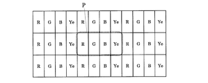
- FIG. 2 shows a specific pixel structure (subpixel arrangement) of the liquid crystal display panel.
- each of the plurality of pixels P includes four types of sub-pixels that display different colors. Specifically, the four types of sub-pixels display a red sub-pixel R that displays red, a green sub-pixel G that displays green, and a blue sub-pixel B that displays blue, and different colors from red, green, and blue. This is the sub pixel X to be used. Within each pixel P, these four types of sub-pixels are arranged in one row and four columns.
- the total number of the plurality of pixels P of the liquid crystal display panel is referred to as “display resolution”.
- the display resolution when m pixels P are arranged in the row direction and n pixels in the column direction is expressed as “m ⁇ n”.
- the minimum display unit of the input image is also referred to as “pixel”, and the total number of pixels of the input image is referred to as “resolution of the input image”.
- the resolution of an input image composed of m pixels in the row direction and n pixels in the column direction is expressed as “m ⁇ n”.
- the resolution converter 10 shown in FIG. 1 converts the resolution (m 1 ⁇ n 1 ) of an image signal input from the outside so as to match the display resolution (m 2 ⁇ n 2 ) of the four primary color liquid crystal display module 20. To do. Further, the resolution conversion apparatus 10 displays image signals corresponding to the three primary colors (red, green, and blue) by the four primary colors (red, green, and blue displayed by the red subpixel R, the green subpixel G, and the blue subpixel B). And the color displayed by the sub-pixel X). A more specific configuration of the resolution conversion apparatus 10 will be described later.
- a sub-pixel for convenience, referred to as a “first sub-pixel” that displays a color with the highest luminance among the four types of sub-pixels.
- the sub-pixel displaying the second highest luminance color (referred to as “second sub-pixel” for convenience) are not adjacent to each other (that is, sandwiching at least one sub-pixel).
- FIG. 2 shows an example of subpixel arrangement when the first subpixel is the green subpixel G and the second subpixel is the subpixel X. In the example shown in FIG.
- each pixel P in each pixel P, four types of sub-pixels are arranged in the order of red sub-pixel R, green sub-pixel G, blue sub-pixel B, and sub-pixel X from left to right.
- the green subpixel G and the subpixel X are not adjacent to each other.
- the four types of sub-pixels are a plurality of display units each capable of displaying a specific color, and each of them is represented by one or two or more continuous sub-pixels. It contains multiple display units that are configured.
- the four types of sub-pixels have a plurality of display units of intermediate sizes between the pixels and the sub-pixels for a specific color (one of which may be the same size as the sub-pixel as will be described later). ) Can be prescribed.
- a sub-pixel X and a display unit configured by sub-pixels that display colors complementary to the colors displayed by the sub-pixels X are defined.
- the display resolution of the input image when the resolution of the input image is higher than the display resolution (that is, when the total number of pixels of the input image is larger than the total number of the plurality of pixels P of the liquid crystal display panel), Each display unit can be displayed as a virtual pixel. Therefore, the visual resolution can be improved.
- the color with the highest luminance is displayed (that is, the luminance at the highest gradation is the highest) and the color with the second highest luminance is displayed (that is, the highest level). Since the second sub-pixel is arranged so as not to be adjacent in the pixel P), the first sub-pixel and the second sub-pixel are arranged adjacent to each other. In comparison, the spatial frequency of the luminance distribution can be increased, and two adjacent virtual pixels can be prevented from being merged and viewed.
- FIG. 3 shows an example of sub-pixel arrangement when the sub-pixel X is a yellow sub-pixel Ye that displays yellow.
- each of the plurality of pixels P includes a red sub-pixel R, a green sub-pixel G, a blue sub-pixel B, and a yellow sub-pixel Ye.
- the red sub-pixel R, the green sub-pixel G, the blue sub-pixel B, and the yellow sub-pixel Ye are arranged in this order from the left side to the right side.
- Table 1 shows an example of Y values (Y values when lighted at the highest gradation) of the red subpixel R, the green subpixel G, the blue subpixel B, and the yellow subpixel Ye.
- the Y value of each sub-pixel indicates a relative value with respect to the Y value of the pixel P during white display being 100%.
- the yellow value of the yellow subpixel Ye is the largest, and the Y value of the green subpixel G is the second largest. That is, among the four primary colors displayed by the four types of sub-pixels, the yellow luminance (lightness) displayed by the yellow sub-pixel Ye is the highest, and the green luminance (lightness) displayed by the green sub-pixel G is the highest. Second highest. As shown in FIG. 3, the yellow sub-pixel Ye that displays yellow with the highest luminance and the green sub-pixel G that displays green with the second highest luminance are not adjacent to each other.
- the four types of sub-pixels are a first display composed of a red sub-pixel R, a green sub-pixel G, and a blue sub-pixel B as shown in FIG. 4A as a plurality of display units for displaying white.
- the unit DU1 and the second display unit DU2 configured by the blue sub-pixel B and the yellow sub-pixel Ye as shown in FIG. 4B are included. Since the first display unit DU1 is composed of the red sub-pixel R, the green sub-pixel G, and the blue sub-pixel B that display the three primary colors of light, red, green, and blue, white can be displayed. Further, since the second display unit DU2 includes the blue sub-pixel B and the yellow sub-pixel Ye that display blue and yellow that are complementary to each other, it is also possible to display white.
- the four types of sub-pixels include a first display unit DU1 configured by a red sub-pixel R and a green sub-pixel G as shown in FIG. 5A as a plurality of display units for displaying yellow. , And a second display unit DU2 constituted by yellow sub-pixels Ye as shown in FIG. Since the first display unit DU1 is composed of the red sub-pixel R and the green sub-pixel G that display red and green that become yellow when mixed colors, yellow can be displayed. Further, since the second display unit DU2 is composed of only the yellow sub-pixel Ye that displays yellow, it can also display yellow.
- each pixel P includes a plurality of display units each capable of displaying a specific color. Since each of these can be displayed as virtual pixels, visual resolution can be improved.
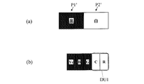
- FIG. 6A shows two pixels P1 'and P2' that are continuous along the row direction of the input image. As shown in FIG. 6A, the color of the left pixel P1 'is black and the color of the right pixel P2' is white.
- FIG. 6B shows a general reduction process in a liquid crystal display device that performs display using three primary colors (that is, each pixel P includes a red sub-pixel R, a green sub-pixel G, and a blue sub-pixel B).
- each pixel P includes a red sub-pixel R, a green sub-pixel G, and a blue sub-pixel B.
- the lighting state of the pixel P corresponding to the two pixels P1 ′ and P2 ′ of the input image is shown.
- the red sub-pixel R, the green sub-pixel G, and the blue sub-pixel B are all lit in the same halftone, and the pixel P as a whole displays gray.
- the luminance of the pixel P is the average of the luminance of the pixel P1 'and the luminance of the pixel P2' of the input image when a general reduction process such as the bilinear method is performed. For this reason, if the input image with the stripe as described above is reduced to 1 ⁇ 2, it becomes a gray solid image.
- FIG. 6C shows a lighting state of the pixel P corresponding to the two pixels P1 'and P2' of the input image when the reduction process is performed in the liquid crystal display device 100 of the present embodiment.
- the red sub-pixel R and the green sub-pixel G are not lit (that is, the lowest gradation is displayed), and the blue sub-pixel constituting the second display unit DU2.
- B and yellow sub-pixel Ye are lit at the highest gradation. Therefore, the left side of the pixel P displays black as a virtual pixel, and the right side of the pixel P displays white as a virtual pixel. Therefore, the visual resolution is improved, and display can be performed at a resolution higher (specifically, twice) than the display resolution of the liquid crystal display device 100 (defined by the total number of the plurality of pixels P).
- a yellow sub-pixel (first sub-pixel) Ye that displays the color with the highest luminance
- a green sub-pixel (second sub-pixel) G that displays the color with the second highest luminance.
- FIG. 7A shows an arrangement in which the yellow sub-pixel Ye and the green sub-pixel G are not adjacent to each other
- FIG. 7B shows an arrangement in which the yellow sub-pixel Ye and the green sub-pixel G are adjacent to each other.
- the gradation displayed by each sub-pixel is the same.
- the yellow sub-pixel Ye that displays the highest luminance color and the green sub-pixel G that displays the second highest luminance color are adjacent to each other.
- two adjacent virtual pixels are fused and viewed.
- the yellow sub-pixel Ye that displays the highest luminance color and the green sub-pixel G that displays the second highest luminance color are not adjacent to each other. The spatial frequency of the distribution becomes high and the occurrence of such a problem is prevented.
- each display unit is virtually set. Display can be performed as pixels. Therefore, when the color of two pixels that are continuous along the row direction of the input image is a specific color, black from the left side, and on the contrary, when the color of the input image is black, a specific color from the left side, The luminances of the four types of sub-pixels constituting the pixel P corresponding to the two pixels are at least partially different. That is, the output in units of subpixels is different between the former case and the latter case.
- FIG. 9A when the colors of the two pixels P1 ′ and P2 ′ in the input image are black and yellow from the left side, as shown in FIG.
- the yellow sub-pixel Ye (sub-pixel constituting the second display unit DU2 for yellow) is turned on, and the red sub-pixel R, the green sub-pixel G, and the blue sub-pixel B are turned off. Remains.
- the first subpixel and the second subpixel are used.
- the luminance of the green subpixel G positioned relatively to the left in one pixel is higher than the luminance of the yellow subpixel Ye positioned relatively to the right
- the luminance of the yellow subpixel Ye positioned relatively on the right side in one pixel is higher than the luminance of the green subpixel G positioned relatively on the left side.
- each of a plurality of display units for a specific color is configured by one subpixel (second display unit DU2 for yellow).
- second display unit DU2 for yellow two or more sub-pixels continuous within one pixel
- first display unit DU1 and second display unit DU2 for white, first display unit DU1 for yellow two or more sub-pixels continuous within one pixel
- the present invention is not limited to such a subpixel arrangement.
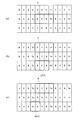
- FIG. 10A shows another example of subpixel arrangement.
- the four types of sub-pixels are in the order of blue sub-pixel B, green sub-pixel G, red sub-pixel R, yellow sub-pixel Ye from left to right. Is arranged. Even in this arrangement, the yellow sub-pixel Ye that displays yellow with the highest luminance and the green sub-pixel G that displays green with the second highest luminance are not adjacent to each other.
- the four types of sub-pixels arranged as shown in FIG. 10A are used as a plurality of display units for displaying white, such as a red sub-pixel R and a green sub-pixel G as shown in FIG. And a first display unit DU1 constituted by the blue sub-pixel B and a second display unit DU2 constituted by the blue sub-pixel B and the yellow sub-pixel Ye as shown in FIG. 10C.
- the second display unit DU2 shown in FIG. 10C is composed of a plurality of subpixels that are continuous across the two pixels P.
- a plurality of display units for a specific color may include one display unit extending over two pixels P.
- the color of a certain two pixels continuous in the row direction of the input image is a specific color, black from the left side, and on the contrary, black from the left side, a specific color
- the output in units of sub-pixels differs depending on the color.
- the first subpixel and the second subpixel are used.
- the luminance of the yellow sub-pixel Ye (see FIG. 10) that is positioned relatively to the right in one of the pixels (the yellow sub-pixel Ye and the green sub-pixel G) is positioned relatively to the left.
- the luminance of the green sub-pixel G positioned relatively to the left in one pixel is higher than that of the green sub-pixel G. It is higher than the luminance of the pixel Ye.
- a difference in luminance distribution can be expressed by turning on the peripheral sub-pixels auxiliary while lighting up. For example, for green, the difference in luminance distribution can be expressed to some extent by lighting the green sub-pixel G and lighting the surrounding sub-pixels supplementarily.
- the output in units of sub-pixels when the color of two pixels continuous along the row direction of the input image is green and black from the left side, and on the contrary, when the color is black and green from the left side. Is different.
- the sub-pixel X displaying a color different from red, green, and blue is the yellow sub-pixel Ye, but the present invention is not limited to this.
- the sub-pixel X may be, for example, a cyan sub-pixel that displays cyan or a magenta sub-pixel that displays magenta.
- FIG. 15 shows a liquid crystal display device 200 according to this embodiment.
- the liquid crystal display device 200 includes a resolution conversion device 11 and a five primary color liquid crystal display module 21, and is a multi-primary color display device that performs display using five primary colors.
- the five primary color liquid crystal display module 21 includes a liquid crystal display panel, a gate driver, a source driver, a timing controller, a backlight (illumination device), and the like.
- the liquid crystal display panel has a plurality of pixels arranged in a matrix including a plurality of rows and a plurality of columns.
- FIG. 16 shows a specific pixel structure (subpixel arrangement) of the liquid crystal display panel.
- each of the plurality of pixels P includes five types of sub-pixels that display different colors.
- the five types of sub-pixels display a red sub-pixel R that displays red, a green sub-pixel G that displays green, and a blue sub-pixel B that displays blue, and different colors from red, green, and blue.
- the sub-pixel X 1 and the sub-pixel X 2 are arranged in one row and five columns.
- the resolution converter 11 shown in FIG. 15 converts the resolution (m 1 ⁇ n 1 ) of the image signal input from the outside so as to match the display resolution (m 2 ⁇ n 2 ) of the five primary color liquid crystal display module 21. To do.
- the resolution conversion device 11 also displays image signals corresponding to the three primary colors (red, green, and blue) in five primary colors (red, green, and blue displayed by the red subpixel R, the green subpixel G, and the blue subpixel B). And the color displayed by the sub-pixel X 1 and the color displayed by the sub-pixel X 2 ).
- a sub-pixel that displays the color with the highest luminance among the five types of sub-pixels and the second highest luminance.
- the sub-pixels (second sub-pixels) for displaying colors are arranged so as not to be adjacent (that is, sandwiching at least one sub-pixel).
- FIG. 16 shows an example of the sub-pixel arrangement when the first sub-pixel is the sub-pixel X 2 and the second sub-pixel is the sub-pixel X 1 . In the example shown in FIG.
- each pixel P five types of sub-pixels are red sub-pixel R, sub-pixel X 1 , green sub-pixel G, blue sub-pixel B, sub-pixel X from left to right.
- the sub-pixel X 1 and the sub-pixel X 2 are not adjacent to each other.
- the five types of sub-pixels are a plurality of display units each capable of displaying a specific color, and each of them is represented by one or two or more continuous sub-pixels. It contains multiple display units that are configured. That is, the five types of sub-pixels can define a plurality of display units having a size intermediate between the pixel and the sub-pixel (one of which may be the same size as the sub-pixel) for a specific color. .
- the liquid crystal display device 200 when the resolution of the input image is higher than the display resolution (that is, when the total number of pixels of the input image is larger than the total number of the plurality of pixels P of the liquid crystal display panel), Each of the plurality of display units can be displayed as a virtual pixel. Therefore, the visual resolution can be improved. Further, in the liquid crystal display device 200 according to the present embodiment, the first subpixel that displays the color with the highest luminance and the second subpixel that displays the color with the second highest luminance are not adjacent to each other in the pixel P. Therefore, the spatial frequency of the luminance distribution can be increased compared to the case where the first subpixel and the second subpixel are arranged adjacent to each other, and two adjacent virtual pixels are fused. Visual recognition can be prevented.
- FIG. 17 shows an example of a pixel structure when the sub pixel X 1 is a cyan sub pixel C that displays cyan and the sub pixel X 2 is a yellow sub pixel Ye that displays yellow.
- each of the plurality of pixels P includes a red sub-pixel R, a green sub-pixel G, a blue sub-pixel B, a cyan sub-pixel C, and a yellow sub-pixel Ye. These sub-pixels are arranged in the order of red sub-pixel R, cyan sub-pixel C, green sub-pixel G, blue sub-pixel B, and yellow sub-pixel Ye from left to right.
- Table 2 shows an example of Y values (Y values when lighted at the highest gradation) of the red sub-pixel R, green sub-pixel G, blue sub-pixel B, cyan sub-pixel C, and yellow sub-pixel Ye.
- the Y value of each sub-pixel indicates a relative value with respect to the Y value of the pixel P during white display being 100%.
- the yellow value of the yellow subpixel Ye is the largest, and the Y value of the cyan subpixel C is the second largest. That is, among the five primary colors displayed by the five types of sub-pixels, the yellow luminance (lightness) displayed by the yellow sub-pixel Ye is the highest, and the cyan luminance (lightness) displayed by the cyan sub-pixel C is 2 The second highest. As shown in FIG. 17, the yellow sub-pixel Ye that displays yellow with the highest luminance and the cyan sub-pixel C that displays cyan with the second highest luminance are not adjacent to each other.
- the five types of sub-pixels are a first display unit DU1 configured by a red sub-pixel R and a cyan sub-pixel C as shown in FIG. 18A as a plurality of display units for displaying white, and FIG. As shown in (b), a second display unit DU2 including a blue sub-pixel B and a yellow sub-pixel Ye is included. Since the first display unit DU1 is composed of the red sub-pixel R and the cyan sub-pixel C that display red and cyan that are complementary to each other, white can be displayed. Further, since the second display unit DU2 includes the blue sub-pixel B and the yellow sub-pixel Ye that display blue and yellow that are complementary to each other, it is also possible to display white.
- each pixel P includes a plurality of display units each capable of displaying a specific color. Since each of these can be displayed as virtual pixels, visual resolution can be improved.
- the color of a certain two pixels continuous in the row direction of the input image is a specific color, black from the left side, and on the contrary, the color from the left side is black, the specific color
- the brightness of the five types of sub-pixels constituting the pixel P corresponding to the two pixels in the input image is at least partially different from the case where That is, the output in units of subpixels is different between the former case and the latter case.
- the liquid crystal display device In 200 corresponding pixels P, the red sub-pixel R and the cyan sub-pixel C (sub-pixels constituting the first display unit DU1) are turned on, and the green sub-pixel G, the blue sub-pixel B, and the yellow sub-pixel Ye are turned off. It remains.
- the colors of the two pixels P1 ′ and P2 ′ in the input image are black and white from the left as shown in FIG.
- the blue sub-pixel B and the yellow sub-pixel Ye (sub-pixels constituting the second display unit DU2) are turned on, and the red sub-pixel R, the cyan sub-pixel C, and the green sub-pixel G are turned off. The state remains.
- the first subpixel and the second subpixel are used.
- the luminance of the cyan sub-pixel C positioned relatively to the left in one pixel is higher than the luminance of the yellow sub-pixel Ye positioned relatively to the right, the latter
- the luminance value of the yellow sub-pixel Ye positioned relatively on the right side in one pixel is higher than the luminance value of the cyan sub-pixel C positioned relatively on the left side.
- each of the plurality of display units for white is composed of a plurality of subpixels that are continuous within one pixel.
- the present invention is not limited to such a subpixel arrangement.
- FIG. 21A shows another example of sub-pixel arrangement.
- five types of sub-pixels are blue sub-pixel B, green sub-pixel G, cyan sub-pixel C, red sub-pixel R, yellow sub-pixel from left to right.
- the pixels Ye are arranged in this order. Even in this arrangement, the yellow sub-pixel Ye that displays yellow with the highest luminance and the cyan sub-pixel C that displays cyan with the second highest luminance are not adjacent to each other.
- the five types of sub-pixels arranged as shown in FIG. 21A are represented by a red sub-pixel R and a cyan sub-pixel C as shown in FIG. 21B as a plurality of display units for displaying white.
- the first display unit DU1 configured and the second display unit DU2 configured by the blue sub-pixel B and the yellow sub-pixel Ye as shown in FIG. 21C are included.
- the second display unit DU2 shown in FIG. 21C is composed of a plurality of sub-pixels that are continuous across the two pixels P.
- a plurality of display units for a specific color may include one display unit extending over two pixels P.
- the color of a certain two pixels continuous in the row direction of the input image is a specific color, black from the left side, and on the contrary, black from the left side, a specific color
- the output in units of sub-pixels differs depending on the color.
- the first subpixel and the second subpixel are used.
- the luminance of the yellow sub-pixel Ye (see FIG. 21) positioned relatively to the right in one pixel (the yellow sub-pixel Ye and the cyan sub-pixel C) is the cyan sub positioned relatively to the left.
- the luminance of the cyan sub-pixel C positioned relatively to the left in one pixel is higher than that of the yellow sub-pixel Ye positioned relatively to the right. Higher than brightness.
- the present invention is not limited thereto. Is not to be done.
- a magenta subpixel that displays magenta may be used instead of one of the cyan subpixel C and the yellow subpixel Ye.
- a plurality of subpixels constituting one pixel P may include a plurality of subpixels displaying the same color.
- each pixel P may be composed of two red subpixels R, a green subpixel G, a blue subpixel B, a yellow subpixel Ye, and a cyan subpixel C.
- there are five types of sub-pixels constituting each pixel P but the number is six.
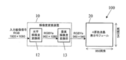
- FIG. 24 shows an example of a specific configuration of the resolution conversion apparatus 10.
- the number of pixels of the input image is 1920 in the horizontal direction and 1080 in the vertical direction, and the resolution of the input image is a so-called Full-HD resolution.
- Such an input image is displayed using the four primary color liquid crystal display module 20.
- the number of pixels of the liquid crystal display panel of the four-primary-color liquid crystal display module 20 is 960 in the horizontal direction and 540 in the vertical direction, and resolution conversion of 1/2 is performed in both the horizontal direction and the vertical direction.
- the resolution conversion apparatus 10 shown in FIG. 24 includes a horizontal resolution conversion unit 12 and a vertical resolution conversion unit 13.
- An image signal input from the outside is first input to the horizontal resolution conversion unit 12 and the number of pixels in the horizontal direction is compressed to 1 ⁇ 2.
- the number of physical pixels in the horizontal direction is 960.
- each of the two display units having intermediate sizes between the sub-pixels and the pixels is virtually displayed. Since it can be used as a typical pixel, it can hold 1920 times double the visual resolution. In other words, the horizontal direction can be displayed on a liquid crystal display panel having half the number of pixels without any deterioration in resolution.
- the signal output from the horizontal resolution converter 12 is sent to the vertical resolution converter 13 for vertical processing, and the number of pixels in the vertical direction is compressed to 1 ⁇ 2.
- the resolution conversion in the vertical direction is performed by a conventional method. Since the resolution of the human eye is lower in the vertical direction than in the horizontal direction, such processing in the vertical direction has little effect on the resolution.
- the signal whose resolution has been converted in both the horizontal direction and the vertical direction is input to the four primary color liquid crystal display module 20.
- the four primary color liquid crystal display module 20 includes a liquid crystal display panel, a gate driver, a source driver, a timing controller, a backlight (illumination device), and the like, and an input signal is a gate driver and a source driver controlled by the timing controller. Is displayed on the liquid crystal display panel as an image.
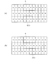
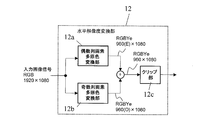
- FIG. 25 shows an example of a specific configuration of the horizontal resolution conversion unit 12.
- the horizontal resolution conversion unit 12 illustrated in FIG. 25 includes an even column pixel multi-primary color conversion unit 12a, an odd column pixel multi-primary color conversion unit 12b, and a clip unit 12c.
- the image signal input to the horizontal resolution conversion unit 12 is first separated into a component corresponding to an even column pixel and a component corresponding to an odd column pixel, and the even column pixel multi-primary color conversion unit 12a and the odd column Different primary color conversions (conversion from three colors to four colors) are performed in the pixel multi-primary color conversion unit 12b, and then recombined. At this point, the number of horizontal pixels is halved.
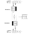
- FIG. 26 schematically shows specific processing for even-numbered pixels and odd-numbered pixels in the input image.
- the signal processing is performed so that the pixels in the even-numbered columns are basically expressed by the subset S1 of the red sub-pixel R and the green sub-pixel G.
- the yellow sub-pixel Ye and the blue sub-pixel B adjacent to the subset S1 are also used supplementarily.
- At least a part of the subset S1 and the auxiliary yellow subpixel Ye and blue subpixel B function as an intermediate “display unit” as described above.
- signal processing is performed so that the pixels in the odd-numbered columns are represented by the subset S2 of the blue subpixel B and the yellow subpixel Ye.
- the green sub-pixel G and the red sub-pixel R adjacent to the subset S2 are also used supplementarily.
- At least a part of the subset S2 and the auxiliary green subpixel G and red subpixel R function as an intermediate “display unit” as described above.
- the three primary color signals of the input image are expressed by four types of sub-pixels for each of even-numbered column pixels and odd-numbered column pixels.
- Four primary color image data reduced to / 2 can be obtained.
- overflow may occur after addition in units of sub-pixels.
- clipping is performed by the clip unit 12c at the final stage as a countermeasure against overflow (see FIG. 25). Normalization may be performed at the time of assignment to each subset so as not to occur.
- the even-numbered pixels of the input image are represented by the subset S1 and the odd-numbered pixels are represented by the subset S2, so that it is possible to express twice the display resolution.
- a resolution of 1920 pixels can be expressed on a liquid crystal display panel having 960 pixels in the horizontal direction.
- FIG. 27 shows another example of a specific configuration of the horizontal resolution conversion unit 12.
- 27 includes a low-pass filter (LPF) 12d, a high-pass filter (HPF) 12e, a multi-primary color conversion unit 12f, a luminance conversion unit 12g, a sampling unit 12h, a sub-pixel rendering unit 12i, and a clip unit 12j.
- LPF low-pass filter
- HPF high-pass filter
- the input image signal is processed by being separated into a low-frequency signal and a high-frequency signal by the LPF 12d and the HPF 12e.
- the low-frequency signal that has passed through the LPF 12d is subjected to multi-primary color conversion (conversion from three colors to four colors) by the multi-primary color conversion unit 12f, and then sampled at the resolution on the liquid crystal display panel side by the sampling unit 12h. Since the high frequency component does not exist in the signal obtained as a result, the resolution is deteriorated but the color component is correctly stored.
- the high frequency signal that has passed through the HPF 12e is converted into the luminance signal Y by the luminance conversion unit 12g, and then, by the sub-pixel rendering unit 12i, as shown schematically in FIG.
- Each pixel is assigned to subsets S1 and S2.
- the subset S1 composed of the red sub-pixel R and the green sub-pixel G is controlled so as to express the high-frequency luminance component of the even-numbered column pixels.
- the subset S2 composed of the blue sub-pixel B and the yellow sub-pixel Ye is controlled to express the high-frequency luminance component of the odd-numbered column pixels.
- the subset S1 is composed of the red sub-pixel R and the green sub-pixel G, so that not only luminance expression but also coloring occurs.
- the HPF 12e is designed appropriately (by setting the cut-off frequency fc above the color separation limit frequency, it is colored).
- such a problem can be avoided by additionally controlling lighting of the sub-pixels adjacent to each of the subsets S1 and S2.
- the number of pixels is halved in the horizontal direction. It is possible to reproduce input signals stored in both color and resolution on the LCD panel.
- the operation and purpose of the clip unit 12j are the same as in the example shown in FIG.
- a multi-primary color display device in which a reduction in display quality is suppressed even when the resolution of the input image is higher than the resolution of the display device. Since the multi-primary color display device according to the present invention can perform high-quality display, it is suitably used for various electronic devices such as liquid crystal televisions.
Abstract
Description
図1に、本実施形態における液晶表示装置100を示す。液晶表示装置100は、図1に示すように、解像度変換装置10と、4原色液晶表示モジュール20とを備え、4つの原色を用いて表示を行う多原色表示装置である。

図15に、本実施形態における液晶表示装置200を示す。液晶表示装置200は、図15に示すように、解像度変換装置11と、5原色液晶表示モジュール21とを備え、5つの原色を用いて表示を行う多原色表示装置である。

本発明の表示装置に用いられる解像度変換装置の具体的な構成を、図1に示した液晶表示装置100の解像度変換装置10を例として説明する。
12 水平解像度変換部
13 垂直解像度変換部
20 4原色液晶表示モジュール
21 5原色液晶表示モジュール
100、200 液晶表示装置
P 画素
R 赤サブ画素
G 緑サブ画素
B 青サブ画素
C シアンサブ画素
Ye 黄サブ画素
DU1 第1表示単位
DU2 第2表示単位
Claims (13)
- 複数の行および複数の列を含むマトリクス状に配置された複数の画素を有し、前記複数の画素のそれぞれは、互いに異なる色を表示する4種類または5種類のサブ画素によって構成される表示装置であって、
前記複数の画素のそれぞれ内で、前記4種類または5種類のサブ画素のうちのもっとも輝度の高い色を表示する第1サブ画素と2番目に輝度の高い色を表示する第2サブ画素とは隣接しないように配置されており、
前記4種類または5種類のサブ画素は、特定の色をそれぞれが表示し得る複数の表示単位であって、1つまたは連続する2つ以上のサブ画素によってそれぞれが構成される複数の表示単位を含み、
入力画像の解像度が、前記複数の画素の総数によって規定される表示解像度よりも高い場合には、前記複数の表示単位のそれぞれを仮想的な画素として表示を行い得る表示装置。 - 前記複数の画素のそれぞれ内で、前記4種類または5種類のサブ画素は、1行複数列に配置されており、
入力画像の解像度が前記表示解像度よりも高いとき、
入力画像の行方向に沿って連続するある2画素の色が左側から前記特定の色、黒である第1の場合と、左側から黒、前記特定の色である第2の場合とで、
前記表示装置の前記複数の画素のうちの、入力画像の前記ある2画素に対応する画素を構成する前記4種類または5種類のサブ画素の輝度が少なくとも一部異なっている請求項1に記載の表示装置。 - 前記複数の表示単位のそれぞれは、1つまたは1画素内で連続する2つ以上のサブ画素によって構成されており、
前記第1の場合、前記第1サブ画素および前記第2サブ画素のうちの1画素内で相対的に左側に位置する一方のサブ画素の輝度は、相対的に右側に位置する他方のサブ画素の輝度よりも高く、
前記第2の場合、前記第1サブ画素および前記第2サブ画素のうちの1画素内で相対的に右側に位置する一方のサブ画素の輝度は、相対的に左側に位置する他方のサブ画素の輝度よりも高い請求項2に記載の表示装置。 - 前記複数の表示単位のうちのある1つの表示単位は、2つの画素にまたがって連続する2つ以上のサブ画素によって構成されており、
前記第1の場合、前記第1サブ画素および前記第2サブ画素のうちの1画素内で相対的に右側に位置する一方のサブ画素の輝度は、相対的に左側に位置する他方のサブ画素の輝度よりも高く、
前記第2の場合、前記第1サブ画素および前記第2サブ画素のうちの1画素内で相対的に左側に位置する一方のサブ画素の輝度は、相対的に右側に位置する他方のサブ画素の輝度よりも高い請求項2に記載の表示装置。 - 前記複数の画素のそれぞれは、互いに異なる色を表示する4種類のサブ画素によって構成される請求項1から4のいずれかに記載の表示装置。
- 前記4種類のサブ画素は、赤を表示する赤サブ画素、緑を表示する緑サブ画素、青を表示する青サブ画素および黄を表示する黄サブ画素である請求項5に記載の表示装置。
- もっとも輝度の高い色を表示する前記第1サブ画素は、前記黄サブ画素であり、
2番目に輝度の高い色を表示する前記第2サブ画素は、前記緑サブ画素である請求項6に記載の表示装置。 - 前記特定の色が白であるとき、
前記複数の表示単位は、前記赤サブ画素、前記緑サブ画素および前記青サブ画素によって構成される第1表示単位と、前記青サブ画素および前記黄サブ画素によって構成される第2表示単位とである請求項6または7に記載の表示装置。 - 前記特定の色が黄であるとき、
前記複数の表示単位は、前記赤サブ画素および前記緑サブ画素によって構成される第1表示単位と、前記黄サブ画素によって構成される第2表示単位とである請求項6から8のいずれかに記載の表示装置。 - 前記複数の画素のそれぞれは、互いに異なる色を表示する5種類のサブ画素によって構成される請求項1から4のいずれかに記載の表示装置。
- 前記5種類のサブ画素は、赤を表示する赤サブ画素、緑を表示する緑サブ画素、青を表示する青サブ画素、シアンを表示するシアンサブ画素および黄を表示する黄サブ画素である請求項10に記載の表示装置。
- もっとも輝度の高い色を表示する前記第1サブ画素は、前記黄サブ画素であり、
2番目に輝度の高い色を表示する前記第2サブ画素は、前記シアンサブ画素である請求項11に記載の表示装置。 - 前記特定の色が白であるとき、
前記複数の表示単位は、前記赤サブ画素および前記シアンサブ画素によって構成される第1表示単位と、前記青サブ画素および前記黄サブ画素によって構成される第2表示単位とである請求項11または12に記載の表示装置。
Priority Applications (4)
| Application Number | Priority Date | Filing Date | Title |
|---|---|---|---|
| US13/578,744 US20120313843A1 (en) | 2010-02-18 | 2011-02-15 | Display device |
| EP11744629.4A EP2538402A4 (en) | 2010-02-18 | 2011-02-15 | DISPLAY DEVICE |
| JP2012500599A JPWO2011102343A1 (ja) | 2010-02-18 | 2011-02-15 | 表示装置 |
| CN201180010088XA CN102770901A (zh) | 2010-02-18 | 2011-02-15 | 显示装置 |
Applications Claiming Priority (2)
| Application Number | Priority Date | Filing Date | Title |
|---|---|---|---|
| JP2010-034097 | 2010-02-18 | ||
| JP2010034097 | 2010-02-18 |
Publications (1)
| Publication Number | Publication Date |
|---|---|
| WO2011102343A1 true WO2011102343A1 (ja) | 2011-08-25 |
Family
ID=44482928
Family Applications (1)
| Application Number | Title | Priority Date | Filing Date |
|---|---|---|---|
| PCT/JP2011/053158 WO2011102343A1 (ja) | 2010-02-18 | 2011-02-15 | 表示装置 |
Country Status (5)
| Country | Link |
|---|---|
| US (1) | US20120313843A1 (ja) |
| EP (1) | EP2538402A4 (ja) |
| JP (1) | JPWO2011102343A1 (ja) |
| CN (1) | CN102770901A (ja) |
| WO (1) | WO2011102343A1 (ja) |
Cited By (9)
| Publication number | Priority date | Publication date | Assignee | Title |
|---|---|---|---|---|
| WO2013035679A1 (ja) * | 2011-09-07 | 2013-03-14 | シャープ株式会社 | 多原色表示装置 |
| JP2013092645A (ja) * | 2011-10-26 | 2013-05-16 | Sharp Corp | 多原色表示装置 |
| WO2014087963A1 (ja) * | 2012-12-05 | 2014-06-12 | シャープ株式会社 | 多原色表示装置 |
| EP2800086A1 (en) * | 2011-12-27 | 2014-11-05 | Mitsubishi Electric Corporation | Display device |
| WO2015037524A1 (ja) * | 2013-09-10 | 2015-03-19 | シャープ株式会社 | 表示装置 |
| WO2015111723A1 (ja) * | 2014-01-27 | 2015-07-30 | シャープ株式会社 | 多原色表示装置 |
| WO2015152004A1 (ja) * | 2014-03-31 | 2015-10-08 | シャープ株式会社 | 多原色表示装置 |
| KR20160052460A (ko) * | 2014-09-26 | 2016-05-12 | 보에 테크놀로지 그룹 컴퍼니 리미티드 | 화상을 디스플레이하기 위한 방법 및 디스플레이 디바이스 |
| JP2018088625A (ja) * | 2016-11-29 | 2018-06-07 | 株式会社富士通ゼネラル | 画像処理装置 |
Families Citing this family (20)
| Publication number | Priority date | Publication date | Assignee | Title |
|---|---|---|---|---|
| US10243023B2 (en) | 2013-01-18 | 2019-03-26 | Universal Display Corporation | Top emission AMOLED displays using two emissive layers |
| US10580832B2 (en) | 2013-01-18 | 2020-03-03 | Universal Display Corporation | High resolution low power consumption OLED display with extended lifetime |
| US10229956B2 (en) | 2013-01-18 | 2019-03-12 | Universal Display Corporation | High resolution low power consumption OLED display with extended lifetime |
| US10304906B2 (en) | 2013-01-18 | 2019-05-28 | Universal Display Corporation | High resolution low power consumption OLED display with extended lifetime |
| US20170287987A9 (en) * | 2013-01-18 | 2017-10-05 | Universal Display Corporation | High resolution low power consumption oled display with extended lifetime |
| US9590017B2 (en) | 2013-01-18 | 2017-03-07 | Universal Display Corporation | High resolution low power consumption OLED display with extended lifetime |
| US10147350B2 (en) * | 2013-07-26 | 2018-12-04 | Darwin Hu | Method and apparatus for increasing perceived display resolutions from an input image |
| US10700134B2 (en) | 2014-05-27 | 2020-06-30 | Universal Display Corporation | Low power consumption OLED display |
| CN104157231B (zh) | 2014-07-23 | 2016-08-17 | 京东方科技集团股份有限公司 | 一种图像的显示方法及显示装置 |
| CN105096801B (zh) * | 2015-08-14 | 2017-07-11 | 京东方科技集团股份有限公司 | 显示单元、显示面板及其驱动方法和显示装置 |
| CN105609033A (zh) * | 2015-12-18 | 2016-05-25 | 武汉华星光电技术有限公司 | 像素渲染方法、像素渲染装置及显示装置 |
| US20180137602A1 (en) * | 2016-11-14 | 2018-05-17 | Google Inc. | Low resolution rgb rendering for efficient transmission |
| US10546521B2 (en) * | 2017-05-16 | 2020-01-28 | Darwin Hu | Resolutions by modulating both amplitude and phase in spatial light modulators |
| JP7015324B2 (ja) | 2017-08-31 | 2022-02-02 | クンシャン ゴー-ビシオノクス オプト-エレクトロニクス カンパニー リミテッド | ピクセル構造、oledディスプレイデバイス、および駆動方法 |
| CN109427265B (zh) * | 2017-08-31 | 2020-10-16 | 昆山国显光电有限公司 | 像素驱动方法 |
| CN110221451A (zh) | 2018-03-02 | 2019-09-10 | 台达电子工业股份有限公司 | 显示装置及显示方法 |
| US10797112B2 (en) | 2018-07-25 | 2020-10-06 | Universal Display Corporation | Energy efficient OLED TV |
| CN111381397A (zh) * | 2018-12-29 | 2020-07-07 | 华为终端有限公司 | 一种显示屏及终端 |
| CN110989239A (zh) * | 2019-12-18 | 2020-04-10 | 京东方科技集团股份有限公司 | 一种像素结构、显示基板和显示装置 |
| CN111415610B (zh) * | 2020-04-26 | 2021-07-23 | Tcl华星光电技术有限公司 | 虚拟像素的电压调节方法、显示面板及存储介质 |
Citations (6)
| Publication number | Priority date | Publication date | Assignee | Title |
|---|---|---|---|---|
| JP2001209047A (ja) | 2000-01-25 | 2001-08-03 | Sharp Corp | 液晶表示装置 |
| JP2004529396A (ja) * | 2001-06-11 | 2004-09-24 | ゲノア・テクノロジーズ・リミテッド | カラーディスプレイ用の装置、システム、および方法 |
| JP2005523465A (ja) * | 2002-04-11 | 2005-08-04 | ジェノア・カラー・テクノロジーズ・リミテッド | 属性を向上させるカラー表示装置および方法 |
| JP2008152244A (ja) * | 2006-11-22 | 2008-07-03 | Canon Inc | 表示装置 |
| WO2008090845A1 (ja) * | 2007-01-25 | 2008-07-31 | Sharp Kabushiki Kaisha | 多原色表示装置 |
| WO2009034714A1 (ja) * | 2007-09-13 | 2009-03-19 | Sharp Kabushiki Kaisha | 多原色液晶表示装置 |
Family Cites Families (6)
| Publication number | Priority date | Publication date | Assignee | Title |
|---|---|---|---|---|
| US8289266B2 (en) * | 2001-06-11 | 2012-10-16 | Genoa Color Technologies Ltd. | Method, device and system for multi-color sequential LCD panel |
| EP1388818B1 (en) * | 2002-08-10 | 2011-06-22 | Samsung Electronics Co., Ltd. | Method and apparatus for rendering image signal |
| DE602004014250D1 (de) * | 2003-01-28 | 2008-07-17 | Genoa Color Technologies Ltd | Subpixel-anordnung für displays mit mehr als drei primärfarben |
| US7495722B2 (en) * | 2003-12-15 | 2009-02-24 | Genoa Color Technologies Ltd. | Multi-color liquid crystal display |
| US7742128B2 (en) * | 2006-11-22 | 2010-06-22 | Canon Kabushiki Kaisha | Hybrid color display apparatus having large pixel and small pixel display modes |
| TW200842694A (en) * | 2007-04-20 | 2008-11-01 | Asustek Comp Inc | Method for dynamically adjusting brightness of image |
-
2011
- 2011-02-15 US US13/578,744 patent/US20120313843A1/en not_active Abandoned
- 2011-02-15 EP EP11744629.4A patent/EP2538402A4/en not_active Withdrawn
- 2011-02-15 CN CN201180010088XA patent/CN102770901A/zh active Pending
- 2011-02-15 WO PCT/JP2011/053158 patent/WO2011102343A1/ja active Application Filing
- 2011-02-15 JP JP2012500599A patent/JPWO2011102343A1/ja active Pending
Patent Citations (6)
| Publication number | Priority date | Publication date | Assignee | Title |
|---|---|---|---|---|
| JP2001209047A (ja) | 2000-01-25 | 2001-08-03 | Sharp Corp | 液晶表示装置 |
| JP2004529396A (ja) * | 2001-06-11 | 2004-09-24 | ゲノア・テクノロジーズ・リミテッド | カラーディスプレイ用の装置、システム、および方法 |
| JP2005523465A (ja) * | 2002-04-11 | 2005-08-04 | ジェノア・カラー・テクノロジーズ・リミテッド | 属性を向上させるカラー表示装置および方法 |
| JP2008152244A (ja) * | 2006-11-22 | 2008-07-03 | Canon Inc | 表示装置 |
| WO2008090845A1 (ja) * | 2007-01-25 | 2008-07-31 | Sharp Kabushiki Kaisha | 多原色表示装置 |
| WO2009034714A1 (ja) * | 2007-09-13 | 2009-03-19 | Sharp Kabushiki Kaisha | 多原色液晶表示装置 |
Non-Patent Citations (3)
| Title |
|---|
| KAZUYOSHI YOSHIYAMA ET AL.: "High Resolution Reproducibility of Multi-Primary Color Displays", PROCEEDINGS OF THE 17TH INTERNATIONAL DISPLAY WORKSHOPS, 1 December 2010 (2010-12-01), pages 1357 - 1359, XP008166003 * |
| M. R. POINTER: "The gamut of real surface colours", COLOR RESEARCH AND APPLICATION, vol. 5, no. 3, 1980, pages 145 - 155 |
| See also references of EP2538402A4 |
Cited By (14)
| Publication number | Priority date | Publication date | Assignee | Title |
|---|---|---|---|---|
| WO2013035679A1 (ja) * | 2011-09-07 | 2013-03-14 | シャープ株式会社 | 多原色表示装置 |
| JP2013092645A (ja) * | 2011-10-26 | 2013-05-16 | Sharp Corp | 多原色表示装置 |
| EP2800086A4 (en) * | 2011-12-27 | 2015-04-15 | Mitsubishi Electric Corp | DISPLAY DEVICE |
| EP2800086A1 (en) * | 2011-12-27 | 2014-11-05 | Mitsubishi Electric Corporation | Display device |
| WO2014087963A1 (ja) * | 2012-12-05 | 2014-06-12 | シャープ株式会社 | 多原色表示装置 |
| WO2015037524A1 (ja) * | 2013-09-10 | 2015-03-19 | シャープ株式会社 | 表示装置 |
| JP2015055645A (ja) * | 2013-09-10 | 2015-03-23 | シャープ株式会社 | 表示装置 |
| WO2015111723A1 (ja) * | 2014-01-27 | 2015-07-30 | シャープ株式会社 | 多原色表示装置 |
| WO2015152004A1 (ja) * | 2014-03-31 | 2015-10-08 | シャープ株式会社 | 多原色表示装置 |
| JP2015197461A (ja) * | 2014-03-31 | 2015-11-09 | シャープ株式会社 | 多原色表示装置 |
| KR20160052460A (ko) * | 2014-09-26 | 2016-05-12 | 보에 테크놀로지 그룹 컴퍼니 리미티드 | 화상을 디스플레이하기 위한 방법 및 디스플레이 디바이스 |
| KR101717868B1 (ko) | 2014-09-26 | 2017-03-17 | 보에 테크놀로지 그룹 컴퍼니 리미티드 | 화상을 디스플레이하기 위한 방법 및 디스플레이 디바이스 |
| US10467939B2 (en) | 2014-09-26 | 2019-11-05 | Boe Technology Group Co., Ltd. | Method for displaying image and display device |
| JP2018088625A (ja) * | 2016-11-29 | 2018-06-07 | 株式会社富士通ゼネラル | 画像処理装置 |
Also Published As
| Publication number | Publication date |
|---|---|
| EP2538402A4 (en) | 2013-08-28 |
| CN102770901A (zh) | 2012-11-07 |
| JPWO2011102343A1 (ja) | 2013-06-17 |
| US20120313843A1 (en) | 2012-12-13 |
| EP2538402A1 (en) | 2012-12-26 |
Similar Documents
| Publication | Publication Date | Title |
|---|---|---|
| WO2011102343A1 (ja) | 表示装置 | |
| JP4913161B2 (ja) | 多原色表示装置 | |
| US7965305B2 (en) | Color display system with improved apparent resolution | |
| WO2014077179A1 (ja) | 多原色表示装置 | |
| US9318075B2 (en) | Image driving using color-compensated image data that has been color-scheme converted | |
| US7505053B2 (en) | Subpixel layouts and arrangements for high brightness displays | |
| JP5938467B2 (ja) | 多原色の画像表示パネルを備える表示装置に表示する画像データの処理方法 | |
| WO2013035679A1 (ja) | 多原色表示装置 | |
| JP5593920B2 (ja) | 液晶表示装置 | |
| JP4805339B2 (ja) | 液晶表示装置 | |
| JP4861523B2 (ja) | 表示装置およびテレビ受信装置 | |
| WO2014038517A1 (ja) | 多原色表示装置 | |
| US9542875B2 (en) | Signal processing method, signal processor, and display device including signal processor | |
| WO2016150041A1 (zh) | 像素排列方法、像素渲染方法及图像显示装置 | |
| US20090021534A1 (en) | Display device | |
| JP5890832B2 (ja) | 多原色表示装置 | |
| WO2013022007A1 (ja) | 表示装置 | |
| WO2012005170A1 (ja) | 多原色液晶表示装置 | |
| WO2015152004A1 (ja) | 多原色表示装置 | |
| WO2012067038A1 (ja) | 多原色表示装置 | |
| JP2008233803A (ja) | 表示装置 | |
| US9659520B2 (en) | Gamma correction method based on a gamma curve obtained from single or multiple primary-color frames | |
| TWI463479B (zh) | Image device and data processing system | |
| US8952999B2 (en) | Image processing device, display device, and image processing method | |
| WO2012067037A1 (ja) | 多原色表示装置 |
Legal Events
| Date | Code | Title | Description |
|---|---|---|---|
| WWE | Wipo information: entry into national phase |
Ref document number: 201180010088.X Country of ref document: CN |
|
| 121 | Ep: the epo has been informed by wipo that ep was designated in this application |
Ref document number: 11744629 Country of ref document: EP Kind code of ref document: A1 |
|
| WWE | Wipo information: entry into national phase |
Ref document number: 2012500599 Country of ref document: JP Ref document number: 2011744629 Country of ref document: EP |
|
| WWE | Wipo information: entry into national phase |
Ref document number: 13578744 Country of ref document: US |
|
| NENP | Non-entry into the national phase |
Ref country code: DE |