以下、図面を参照しながら本発明の実施形態を説明する。なお、以下では液晶表示装置を例示するが、本発明は液晶表示装置に限定されるものではなく、有機EL表示装置などの他の表示装置にも好適に用いられる。
Hereinafter, embodiments of the present invention will be described with reference to the drawings. In addition, although a liquid crystal display device is illustrated below, this invention is not limited to a liquid crystal display device, It uses suitably also for other display devices, such as an organic electroluminescent display device.
(実施形態1)
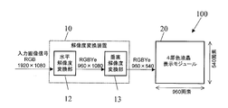
図1に、本実施形態における液晶表示装置100を示す。液晶表示装置100は、図1に示すように、解像度変換装置10と、4原色液晶表示モジュール20とを備え、4つの原色を用いて表示を行う多原色表示装置である。
(Embodiment 1)
FIG. 1 shows a liquid crystal display device 100 according to this embodiment. As shown in FIG. 1, the liquid crystal display device 100 is a multi-primary color display device that includes a resolution conversion device 10 and a four primary color liquid crystal display module 20 and performs display using four primary colors.
4原色液晶表示モジュール20は、ここでは図示していないが、液晶表示パネル、ゲートドライバ、ソースドライバ、タイミングコントローラ、バックライト(照明装置)等を含む。液晶表示パネルは、複数の行および複数の列を含むマトリクス状に配置された複数の画素を有する。
The four primary color liquid crystal display module 20 includes a liquid crystal display panel, a gate driver, a source driver, a timing controller, a backlight (illumination device), etc., which are not shown here. The liquid crystal display panel has a plurality of pixels arranged in a matrix including a plurality of rows and a plurality of columns.
液晶表示パネルの具体的な画素構造(サブ画素配置)を、図2に示す。図2に示すように、複数の画素Pのそれぞれは、互いに異なる色を表示する4種類のサブ画素によって構成される。4種類のサブ画素は、具体的には、赤を表示する赤サブ画素R、緑を表示する緑サブ画素Gおよび青を表示する青サブ画素Bと、赤、緑、青と異なる色を表示するサブ画素Xである。各画素P内で、これら4種類のサブ画素は、1行4列に配置されている。
FIG. 2 shows a specific pixel structure (subpixel arrangement) of the liquid crystal display panel. As shown in FIG. 2, each of the plurality of pixels P includes four types of sub-pixels that display different colors. Specifically, the four types of sub-pixels display a red sub-pixel R that displays red, a green sub-pixel G that displays green, and a blue sub-pixel B that displays blue, and different colors from red, green, and blue. This is the sub pixel X to be used. Within each pixel P, these four types of sub-pixels are arranged in one row and four columns.
本願明細書では、特にことわらない限り、液晶表示パネルの複数の画素Pの総数を「表示解像度」と称する。複数の画素Pが行方向にm個、列方向にn個配置されているときの表示解像度は「m×n」と表記される。また、本願明細書では、入力画像の最小表示単位も「画素」と呼び、入力画像の総画素数を「入力画像の解像度」と称する。この場合も、行方向にm個、列方向にn個の画素から構成される入力画像の解像度は「m×n」と表記される。
In the present specification, unless otherwise specified, the total number of the plurality of pixels P of the liquid crystal display panel is referred to as “display resolution”. The display resolution when m pixels P are arranged in the row direction and n pixels in the column direction is expressed as “m × n”. In the present specification, the minimum display unit of the input image is also referred to as “pixel”, and the total number of pixels of the input image is referred to as “resolution of the input image”. Also in this case, the resolution of an input image composed of m pixels in the row direction and n pixels in the column direction is expressed as “m × n”.
図1に示す解像度変換装置10は、外部から入力された画像信号の解像度(m1×n1)を、4原色液晶表示モジュール20の表示解像度(m2×n2)に一致するように変換する。また、解像度変換装置10は、3つの原色(赤、緑および青)に対応した画像信号を4つの原色(赤サブ画素R、緑サブ画素Gおよび青サブ画素Bが表示する赤、緑および青と、サブ画素Xが表示する色)に対応した多原色信号に変換する。解像度変換装置10のより具体的な構成については後述する。
The resolution converter 10 shown in FIG. 1 converts the resolution (m 1 × n 1 ) of an image signal input from the outside so as to match the display resolution (m 2 × n 2 ) of the four primary color liquid crystal display module 20. To do. Further, the resolution conversion apparatus 10 displays image signals corresponding to the three primary colors (red, green, and blue) by the four primary colors (red, green, and blue displayed by the red subpixel R, the green subpixel G, and the blue subpixel B). And the color displayed by the sub-pixel X). A more specific configuration of the resolution conversion apparatus 10 will be described later.
本実施形態における液晶表示装置100では、複数の画素Pのそれぞれ内で、4種類のサブ画素のうちのもっとも輝度の高い色を表示するサブ画素(便宜的に「第1サブ画素」と呼ぶ。)と2番目に輝度の高い色を表示するサブ画素(便宜的に「第2サブ画素」と呼ぶ。)とが隣接しないように(つまり少なくとも1つのサブ画素を挟むように)配置されている。図2には、第1サブ画素が緑サブ画素Gであり、第2サブ画素がサブ画素Xである場合のサブ画素配置の例を示している。図2に示した例では、各画素P内で、4種類のサブ画素は、左側から右側に向かって赤サブ画素R、緑サブ画素G、青サブ画素B、サブ画素Xの順に配置されており、緑サブ画素Gと、サブ画素Xとは隣接していない。
In the liquid crystal display device 100 according to the present embodiment, among each of the plurality of pixels P, a sub-pixel (for convenience, referred to as a “first sub-pixel”) that displays a color with the highest luminance among the four types of sub-pixels. ) And the sub-pixel displaying the second highest luminance color (referred to as “second sub-pixel” for convenience) are not adjacent to each other (that is, sandwiching at least one sub-pixel). . FIG. 2 shows an example of subpixel arrangement when the first subpixel is the green subpixel G and the second subpixel is the subpixel X. In the example shown in FIG. 2, in each pixel P, four types of sub-pixels are arranged in the order of red sub-pixel R, green sub-pixel G, blue sub-pixel B, and sub-pixel X from left to right. The green subpixel G and the subpixel X are not adjacent to each other.
また、本実施形態における液晶表示装置100では、4種類のサブ画素は、特定の色をそれぞれが表示し得る複数の表示単位であって、1つまたは連続する2つ以上のサブ画素によってそれぞれが構成される複数の表示単位を含んでいる。つまり、4種類のサブ画素は、特定の色について、画素とサブ画素との中間的なサイズの表示単位を複数(後述するようにそのうちの1つはサブ画素と同じサイズであることもあるが)規定することができる。例えば、サブ画素Xが、赤、緑および青のいずれかと補色の関係にある色を表示する場合、白について、赤サブ画素R、緑サブ画素Gおよび青サブ画素Bから構成される表示単位と、サブ画素Xおよびサブ画素Xが表示する色と補色の関係にある色を表示するサブ画素によって構成される表示単位とが規定される。
In the liquid crystal display device 100 according to the present embodiment, the four types of sub-pixels are a plurality of display units each capable of displaying a specific color, and each of them is represented by one or two or more continuous sub-pixels. It contains multiple display units that are configured. In other words, the four types of sub-pixels have a plurality of display units of intermediate sizes between the pixels and the sub-pixels for a specific color (one of which may be the same size as the sub-pixel as will be described later). ) Can be prescribed. For example, when the sub pixel X displays a color complementary to any one of red, green, and blue, a display unit composed of a red sub pixel R, a green sub pixel G, and a blue sub pixel B for white In addition, a sub-pixel X and a display unit configured by sub-pixels that display colors complementary to the colors displayed by the sub-pixels X are defined.
本実施形態における液晶表示装置100では、入力画像の解像度が表示解像度よりも高い場合(つまり入力画像の総画素数が液晶表示パネルの複数の画素Pの総数よりも多い場合)には、上記複数の表示単位のそれぞれを仮想的な画素として表示を行うことができる。そのため、視覚的な解像度を向上させることができる。また、本実施形態における液晶表示装置100では、もっとも輝度の高い色を表示する(つまり最高階調における輝度がもっとも高い)第1サブ画素と2番目に輝度の高い色を表示する(つまり最高階調における輝度が2番目に高い)第2サブ画素とが画素P内で隣接しないように配置されているので、第1サブ画素と第2サブ画素とが隣接するように配置されている場合に比べて輝度分布の空間周波数を高くすることができ、隣接する2つの仮想画素が融合されて視認されることを防止することができる。
In the liquid crystal display device 100 according to the present embodiment, when the resolution of the input image is higher than the display resolution (that is, when the total number of pixels of the input image is larger than the total number of the plurality of pixels P of the liquid crystal display panel), Each display unit can be displayed as a virtual pixel. Therefore, the visual resolution can be improved. In the liquid crystal display device 100 according to the present embodiment, the color with the highest luminance is displayed (that is, the luminance at the highest gradation is the highest) and the color with the second highest luminance is displayed (that is, the highest level). Since the second sub-pixel is arranged so as not to be adjacent in the pixel P), the first sub-pixel and the second sub-pixel are arranged adjacent to each other. In comparison, the spatial frequency of the luminance distribution can be increased, and two adjacent virtual pixels can be prevented from being merged and viewed.
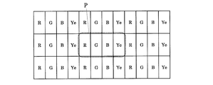
以下、サブ画素Xの具体例を挙げながら、液晶表示装置100の表示態様をより詳細に説明する。図3に、サブ画素Xが黄を表示する黄サブ画素Yeである場合のサブ画素配置の例を示す。図3に示す例では、複数の画素Pのそれぞれは、赤サブ画素R、緑サブ画素G、青サブ画素Bおよび黄サブ画素Yeによって構成され、各画素P内で、4種類のサブ画素は、左側から右側に向かって赤サブ画素R、緑サブ画素G、青サブ画素B、黄サブ画素Yeの順に配置されている。
Hereinafter, the display mode of the liquid crystal display device 100 will be described in more detail with a specific example of the sub-pixel X. FIG. 3 shows an example of sub-pixel arrangement when the sub-pixel X is a yellow sub-pixel Ye that displays yellow. In the example illustrated in FIG. 3, each of the plurality of pixels P includes a red sub-pixel R, a green sub-pixel G, a blue sub-pixel B, and a yellow sub-pixel Ye. The red sub-pixel R, the green sub-pixel G, the blue sub-pixel B, and the yellow sub-pixel Ye are arranged in this order from the left side to the right side.
表1に、赤サブ画素R、緑サブ画素G、青サブ画素Bおよび黄サブ画素YeのY値(最高階調で点灯させたときのY値)の一例を示す。各サブ画素のY値は、白表示時の画素PのY値を100%とし、それに対する相対的な値を示している。
Table 1 shows an example of Y values (Y values when lighted at the highest gradation) of the red subpixel R, the green subpixel G, the blue subpixel B, and the yellow subpixel Ye. The Y value of each sub-pixel indicates a relative value with respect to the Y value of the pixel P during white display being 100%.
表1からわかるように、黄サブ画素YeのY値がもっとも大きく、緑サブ画素GのY値が2番目に大きい。つまり、4種類のサブ画素によって表示される4つの原色のうち、黄サブ画素Yeによって表示される黄の輝度(明度)がもっとも高く、緑サブ画素Gによって表示される緑の輝度(明度)が2番目に高い。もっとも輝度の高い黄を表示する黄サブ画素Yeと、2番目に輝度の高い緑を表示する緑サブ画素Gとは、図3に示されているように、互いに隣接していない。
As can be seen from Table 1, the yellow value of the yellow subpixel Ye is the largest, and the Y value of the green subpixel G is the second largest. That is, among the four primary colors displayed by the four types of sub-pixels, the yellow luminance (lightness) displayed by the yellow sub-pixel Ye is the highest, and the green luminance (lightness) displayed by the green sub-pixel G is the highest. Second highest. As shown in FIG. 3, the yellow sub-pixel Ye that displays yellow with the highest luminance and the green sub-pixel G that displays green with the second highest luminance are not adjacent to each other.
4種類のサブ画素は、白を表示するための複数の表示単位として、図4(a)に示すような、赤サブ画素R、緑サブ画素Gおよび青サブ画素Bによって構成される第1表示単位DU1と、図4(b)に示すような、青サブ画素Bおよび黄サブ画素Yeによって構成される第2表示単位DU2とを含んでいる。第1表示単位DU1は、光の三原色である赤、緑および青を表示する赤サブ画素R、緑サブ画素Gおよび青サブ画素Bによって構成されているので、白を表示することができる。また、第2表示単位DU2は、互いに補色の関係にある青および黄を表示する青サブ画素Bおよび黄サブ画素Yeによって構成されているので、やはり白を表示することができる。
The four types of sub-pixels are a first display composed of a red sub-pixel R, a green sub-pixel G, and a blue sub-pixel B as shown in FIG. 4A as a plurality of display units for displaying white. The unit DU1 and the second display unit DU2 configured by the blue sub-pixel B and the yellow sub-pixel Ye as shown in FIG. 4B are included. Since the first display unit DU1 is composed of the red sub-pixel R, the green sub-pixel G, and the blue sub-pixel B that display the three primary colors of light, red, green, and blue, white can be displayed. Further, since the second display unit DU2 includes the blue sub-pixel B and the yellow sub-pixel Ye that display blue and yellow that are complementary to each other, it is also possible to display white.
また、4種類のサブ画素は、黄を表示するための複数の表示単位として、図5(a)に示すような、赤サブ画素Rおよび緑サブ画素Gによって構成される第1表示単位DU1と、図5(b)に示すような、黄サブ画素Yeによって構成される第2表示単位DU2とを含んでいる。第1表示単位DU1は、混色すると黄になる赤および緑を表示する赤サブ画素Rおよび緑サブ画素Gによって構成されているので、黄を表示することができる。また、第2表示単位DU2は、黄を表示する黄サブ画素Yeのみから構成されているので、やはり黄を表示することができる。
The four types of sub-pixels include a first display unit DU1 configured by a red sub-pixel R and a green sub-pixel G as shown in FIG. 5A as a plurality of display units for displaying yellow. , And a second display unit DU2 constituted by yellow sub-pixels Ye as shown in FIG. Since the first display unit DU1 is composed of the red sub-pixel R and the green sub-pixel G that display red and green that become yellow when mixed colors, yellow can be displayed. Further, since the second display unit DU2 is composed of only the yellow sub-pixel Ye that displays yellow, it can also display yellow.
上述したように、各画素Pを構成する4種類のサブ画素が、それぞれが特定の色を表示し得る複数の表示単位を含んでいることにより、縮小表示を行う場合には、複数の表示単位のそれぞれを仮想的な画素として表示を行うことができるので、視覚的な解像度を向上させることができる。
As described above, the four types of sub-pixels constituting each pixel P include a plurality of display units each capable of displaying a specific color. Since each of these can be displayed as virtual pixels, visual resolution can be improved.
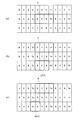
例えば、黒地に幅が1画素分、間隔も1画素分で列方向に延びる白いストライプの入力画像を1/2に縮小表示する場合、図4(a)および(b)に示した第1表示単位DU1および第2表示単位DU2の一方のみを点灯させれば、入力画像と実質的に同じ解像度で表示を行うことができる。この効果を、図6(a)、(b)および(c)を参照しながらより具体的に説明する。
For example, when the input image of a white stripe extending in the column direction with a width of one pixel and an interval of one pixel on a black background is reduced to 1/2, the first display shown in FIGS. If only one of the unit DU1 and the second display unit DU2 is lit, display can be performed with substantially the same resolution as the input image. This effect will be described more specifically with reference to FIGS. 6 (a), (b) and (c).
図6(a)は、入力画像の行方向に沿って連続するある2画素P1’およびP2’を示している。図6(a)に示されているように、左側の画素P1’の色が黒であり、右側の画素P2’の色が白である。
FIG. 6A shows two pixels P1 'and P2' that are continuous along the row direction of the input image. As shown in FIG. 6A, the color of the left pixel P1 'is black and the color of the right pixel P2' is white.
図6(b)は、3原色を用いて表示を行う(つまり各画素Pが赤サブ画素R、緑サブ画素Gおよび青サブ画素Bによって構成される)液晶表示装置において一般的な縮小処理を行った場合に、入力画像の上記2画素P1’およびP2’に対応する画素Pの点灯状態を示している。図6(b)に示されているように、赤サブ画素R、緑サブ画素Gおよび青サブ画素Bがすべて同じ中間調で点灯しており、画素P全体としてグレーを表示している。これは、バイリニア法等の一般的な縮小処理を行った場合、画素Pの輝度は、入力画像の画素P1’の輝度と画素P2’の輝度との平均となるからである。そのため、上述したようなストライプの入力画像を1/2に縮小表示すると、グレーのべた画像になってしまう。
FIG. 6B shows a general reduction process in a liquid crystal display device that performs display using three primary colors (that is, each pixel P includes a red sub-pixel R, a green sub-pixel G, and a blue sub-pixel B). When performed, the lighting state of the pixel P corresponding to the two pixels P1 ′ and P2 ′ of the input image is shown. As shown in FIG. 6B, the red sub-pixel R, the green sub-pixel G, and the blue sub-pixel B are all lit in the same halftone, and the pixel P as a whole displays gray. This is because the luminance of the pixel P is the average of the luminance of the pixel P1 'and the luminance of the pixel P2' of the input image when a general reduction process such as the bilinear method is performed. For this reason, if the input image with the stripe as described above is reduced to ½, it becomes a gray solid image.
図6(c)は、本実施形態の液晶表示装置100において縮小処理を行った場合に、入力画像の上記2画素P1’およびP2’に対応する画素Pの点灯状態を示している。図6(c)に示しているように、赤サブ画素Rおよび緑サブ画素Gは点灯しておらず(つまり最低階調を表示しており)、第2表示単位DU2を構成する青サブ画素Bおよび黄サブ画素Yeが最高階調で点灯している。従って、画素Pの左側が仮想的な画素として黒を表示し、画素Pの右側が仮想的な画素として白を表示している。そのため、視覚的な解像度が向上し、液晶表示装置100の表示解像度(複数の画素Pの総数によって規定される)よりも高い(具体的には2倍の)解像度で表示を行うことができる。
FIG. 6C shows a lighting state of the pixel P corresponding to the two pixels P1 'and P2' of the input image when the reduction process is performed in the liquid crystal display device 100 of the present embodiment. As shown in FIG. 6C, the red sub-pixel R and the green sub-pixel G are not lit (that is, the lowest gradation is displayed), and the blue sub-pixel constituting the second display unit DU2. B and yellow sub-pixel Ye are lit at the highest gradation. Therefore, the left side of the pixel P displays black as a virtual pixel, and the right side of the pixel P displays white as a virtual pixel. Therefore, the visual resolution is improved, and display can be performed at a resolution higher (specifically, twice) than the display resolution of the liquid crystal display device 100 (defined by the total number of the plurality of pixels P).
また、図3に示す例では、もっとも輝度の高い色を表示する黄サブ画素(第1サブ画素)Yeと、2番目に輝度の高い色を表示する緑サブ画素(第2サブ画素)Gとが画素P内で隣接しないように配置されている。このことによる効果を、図7(a)および(b)を参照しながら説明する。
In the example shown in FIG. 3, a yellow sub-pixel (first sub-pixel) Ye that displays the color with the highest luminance, and a green sub-pixel (second sub-pixel) G that displays the color with the second highest luminance. Are arranged so as not to be adjacent in the pixel P. The effect by this is demonstrated referring FIG. 7 (a) and (b).
図7(a)は、黄サブ画素Yeと緑サブ画素Gとが隣接していない配置を示し、図7(b)は、黄サブ画素Yeと緑サブ画素Gとが隣接した配置を示している。図7(a)と図7(b)とでは、各サブ画素が表示している階調は同じである。しかしながら、図7(b)に示す配置では、もっとも輝度の高い色を表示する黄サブ画素Yeと2番目に輝度の高い色を表示する緑サブ画素Gとが隣接しているため、既に述べたような中間的な表示単位を用いた高解像度の表示を行う場合に、隣接する2つの仮想画素が融合されて視認されてしまう。これに対し、図7(a)に示す配置では、もっとも輝度の高い色を表示する黄サブ画素Yeと2番目に輝度の高い色を表示する緑サブ画素Gとが隣接していないため、輝度分布の空間周波数が高くなり、そのような問題の発生が防止される。
FIG. 7A shows an arrangement in which the yellow sub-pixel Ye and the green sub-pixel G are not adjacent to each other, and FIG. 7B shows an arrangement in which the yellow sub-pixel Ye and the green sub-pixel G are adjacent to each other. Yes. In FIG. 7A and FIG. 7B, the gradation displayed by each sub-pixel is the same. However, in the arrangement shown in FIG. 7B, the yellow sub-pixel Ye that displays the highest luminance color and the green sub-pixel G that displays the second highest luminance color are adjacent to each other. When performing high-resolution display using such an intermediate display unit, two adjacent virtual pixels are fused and viewed. On the other hand, in the arrangement shown in FIG. 7A, the yellow sub-pixel Ye that displays the highest luminance color and the green sub-pixel G that displays the second highest luminance color are not adjacent to each other. The spatial frequency of the distribution becomes high and the occurrence of such a problem is prevented.
既に述べたように、本実施形態における液晶表示装置100では、入力画像の解像度が表示解像度よりも高いとき、複数の表示単位が規定され得る特定の色については、各々の表示単位を仮想的な画素として表示を行うことができる。そのため、入力画像の行方向に沿って連続するある2画素の色が左側から特定の色、黒である場合と、それとは反対に左側から黒、特定の色である場合とで、入力画像の上記ある2画素に対応する画素Pを構成する4種類のサブ画素の輝度が少なくとも一部異なっている。つまり、前者の場合と後者の場合とで、サブ画素単位の出力が異なっている。
As already described, in the liquid crystal display device 100 according to the present embodiment, when the resolution of the input image is higher than the display resolution, for a specific color that can define a plurality of display units, each display unit is virtually set. Display can be performed as pixels. Therefore, when the color of two pixels that are continuous along the row direction of the input image is a specific color, black from the left side, and on the contrary, when the color of the input image is black, a specific color from the left side, The luminances of the four types of sub-pixels constituting the pixel P corresponding to the two pixels are at least partially different. That is, the output in units of subpixels is different between the former case and the latter case.
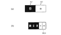
例えば、図8(a)に示すように、入力画像のある2画素P1’およびP2’の色が左側から黄、黒である場合には、図8(b)に示すように、液晶表示装置100の対応する画素Pでは、赤サブ画素Rおよび緑サブ画素G(黄についての第1表示単位DU1を構成するサブ画素)が点灯し、青サブ画素Bおよび黄サブ画素Yeは消灯状態のままである。これに対し、図9(a)に示すように、入力画像のある2画素P1’およびP2’の色が左側から黒、黄である場合には、図9(b)に示すように、液晶表示装置100の対応する画素Pでは、黄サブ画素Ye(黄についての第2表示単位DU2を構成するサブ画素)が点灯し、赤サブ画素R、緑サブ画素Gおよび青サブ画素Bは消灯状態のままである。
For example, as shown in FIG. 8A, when the colors of two pixels P1 ′ and P2 ′ in the input image are yellow and black from the left side, as shown in FIG. 8B, the liquid crystal display device In 100 corresponding pixels P, the red sub-pixel R and the green sub-pixel G (the sub-pixel constituting the first display unit DU1 for yellow) are turned on, and the blue sub-pixel B and the yellow sub-pixel Ye are kept off. It is. On the other hand, as shown in FIG. 9A, when the colors of the two pixels P1 ′ and P2 ′ in the input image are black and yellow from the left side, as shown in FIG. In the corresponding pixel P of the display device 100, the yellow sub-pixel Ye (sub-pixel constituting the second display unit DU2 for yellow) is turned on, and the red sub-pixel R, the green sub-pixel G, and the blue sub-pixel B are turned off. Remains.
また、図8(a)および(b)に示す場合と図9(a)および(b)に示す場合とを比較すればわかるように、前者の場合には、第1サブ画素および第2サブ画素(黄サブ画素Yeおよび緑サブ画素G)のうちの1画素内で相対的に左側に位置する緑サブ画素Gの輝度が、相対的に右側に位置する黄サブ画素Yeの輝度よりも高く、後者の場合には、これとは逆に、1画素内で相対的に右側に位置する黄サブ画素Yeの輝度が、相対的に左側に位置する緑サブ画素Gの輝度よりも高い。
Further, as can be seen from a comparison between the case shown in FIGS. 8A and 8B and the case shown in FIGS. 9A and 9B, in the former case, the first subpixel and the second subpixel are used. Among the pixels (the yellow subpixel Ye and the green subpixel G), the luminance of the green subpixel G positioned relatively to the left in one pixel is higher than the luminance of the yellow subpixel Ye positioned relatively to the right In the latter case, on the contrary, the luminance of the yellow subpixel Ye positioned relatively on the right side in one pixel is higher than the luminance of the green subpixel G positioned relatively on the left side.
なお、図3~図5に例示した画素構造(サブ画素配置)では、特定の色についての複数の表示単位のそれぞれは、1つのサブ画素によって構成されている(黄についての第2表示単位DU2)か、または、1画素内で連続する2つ以上のサブ画素によって構成されている(白についての第1表示単位DU1および第2表示単位DU2、黄についての第1表示単位DU1)。しかしながら、本発明はこのようなサブ画素配置に限定されるものではない。
In the pixel structure (subpixel arrangement) illustrated in FIGS. 3 to 5, each of a plurality of display units for a specific color is configured by one subpixel (second display unit DU2 for yellow). ) Or two or more sub-pixels continuous within one pixel (first display unit DU1 and second display unit DU2 for white, first display unit DU1 for yellow). However, the present invention is not limited to such a subpixel arrangement.
図10(a)に、サブ画素配置の他の例を示す。図10(a)に示す例では、各画素P内で、4種類のサブ画素は、左側から右側に向かって青サブ画素B、緑サブ画素G、赤サブ画素R、黄サブ画素Yeの順に配置されている。この配置においても、もっとも輝度の高い黄を表示する黄サブ画素Yeと、2番目に輝度の高い緑を表示する緑サブ画素Gとは、互いに隣接していない。
FIG. 10A shows another example of subpixel arrangement. In the example shown in FIG. 10A, in each pixel P, the four types of sub-pixels are in the order of blue sub-pixel B, green sub-pixel G, red sub-pixel R, yellow sub-pixel Ye from left to right. Is arranged. Even in this arrangement, the yellow sub-pixel Ye that displays yellow with the highest luminance and the green sub-pixel G that displays green with the second highest luminance are not adjacent to each other.
図10(a)に示すように配置された4種類のサブ画素は、白を表示するための複数の表示単位として、図10(b)に示すような、赤サブ画素R、緑サブ画素Gおよび青サブ画素Bによって構成される第1表示単位DU1と、図10(c)に示すような、青サブ画素Bおよび黄サブ画素Yeによって構成される第2表示単位DU2とを含んでいる。図10(c)に示されている第2表示単位DU2は、2つの画素Pにまたがって連続する複数のサブ画素によって構成されている。このように、特定の色についての複数の表示単位は、そのうちのある1つの表示単位が2つの画素Pにまたがっていてもよい。
The four types of sub-pixels arranged as shown in FIG. 10A are used as a plurality of display units for displaying white, such as a red sub-pixel R and a green sub-pixel G as shown in FIG. And a first display unit DU1 constituted by the blue sub-pixel B and a second display unit DU2 constituted by the blue sub-pixel B and the yellow sub-pixel Ye as shown in FIG. 10C. The second display unit DU2 shown in FIG. 10C is composed of a plurality of subpixels that are continuous across the two pixels P. As described above, a plurality of display units for a specific color may include one display unit extending over two pixels P.
図10に示した配置を採用する場合でも、入力画像の行方向に沿って連続するある2画素の色が左側から特定の色、黒である場合と、それとは反対に左側から黒、特定の色である場合とで、サブ画素単位の出力は異なる。
Even when the arrangement shown in FIG. 10 is adopted, the color of a certain two pixels continuous in the row direction of the input image is a specific color, black from the left side, and on the contrary, black from the left side, a specific color The output in units of sub-pixels differs depending on the color.
例えば、図11(a)に示すように、入力画像のある2画素P1’およびP2’の色が左側から白、黒である場合には、図11(b)に示すように、青サブ画素Bおよび黄サブ画素Ye(第2表示単位DU2を構成するサブ画素)が点灯し、赤サブ画素Rおよび緑サブ画素Gは消灯状態のままである。これに対し、図12(a)に示すように、入力画像のある2画素P1’およびP2’の色が左側から黒、白である場合には、図12(b)に示すように、赤サブ画素R、緑サブ画素Gおよび青サブ画素B(第1表示単位DU1を構成するサブ画素)が点灯し、黄サブ画素Yeは消灯状態のままである。
For example, as shown in FIG. 11A, when the colors of two pixels P1 ′ and P2 ′ in the input image are white and black from the left side, as shown in FIG. The B and yellow sub-pixels Ye (sub-pixels constituting the second display unit DU2) are turned on, and the red sub-pixel R and the green sub-pixel G remain off. On the other hand, as shown in FIG. 12A, when the colors of the two pixels P1 ′ and P2 ′ in the input image are black and white from the left as shown in FIG. The sub-pixel R, the green sub-pixel G, and the blue sub-pixel B (sub-pixels constituting the first display unit DU1) are turned on, and the yellow sub-pixel Ye remains off.
また、図11(a)および(b)に示す場合と図12(a)および(b)に示す場合とを比較すればわかるように、前者の場合には、第1サブ画素および第2サブ画素(黄サブ画素Yeおよび緑サブ画素G)のうちの1画素内で相対的に右側に位置する黄サブ画素Ye(図10を参照されたい。)の輝度は、相対的に左側に位置する緑サブ画素Gの輝度よりも高く、後者の場合には、これとは逆に、1画素内で相対的に左側に位置する緑サブ画素Gの輝度は、相対的に右側に位置する黄サブ画素Yeの輝度よりも高い。
Further, as can be seen from a comparison between the case shown in FIGS. 11A and 11B and the case shown in FIGS. 12A and 12B, in the former case, the first subpixel and the second subpixel are used. The luminance of the yellow sub-pixel Ye (see FIG. 10) that is positioned relatively to the right in one of the pixels (the yellow sub-pixel Ye and the green sub-pixel G) is positioned relatively to the left. In the latter case, the luminance of the green sub-pixel G positioned relatively to the left in one pixel is higher than that of the green sub-pixel G. It is higher than the luminance of the pixel Ye.
なお、4種類のサブ画素によって複数の表示単位が規定されない色については、仮想的な画素を用いた表示を行うことはできないが、その場合でも、その色にもっとも近い色を表示するサブ画素を点灯させつつ、周辺のサブ画素を補助的に点灯させることにより、輝度分布の違いを表現することができる。例えば、緑については、緑サブ画素Gを点灯させつつ、周辺のサブ画素を補助的に点灯させることにより、輝度分布の違いをある程度表現することができる。このときも、入力画像の行方向に沿って連続するある2画素の色が左側から緑、黒である場合と、それとは反対に左側から黒、緑である場合とで、サブ画素単位の出力は異なる。
In addition, for colors in which a plurality of display units are not defined by the four types of sub-pixels, display using virtual pixels cannot be performed, but even in such a case, sub-pixels that display colors closest to the colors are not displayed. A difference in luminance distribution can be expressed by turning on the peripheral sub-pixels auxiliary while lighting up. For example, for green, the difference in luminance distribution can be expressed to some extent by lighting the green sub-pixel G and lighting the surrounding sub-pixels supplementarily. Also in this case, the output in units of sub-pixels when the color of two pixels continuous along the row direction of the input image is green and black from the left side, and on the contrary, when the color is black and green from the left side. Is different.
図13(a)に示すように、入力画像のある2画素P1’およびP2’の色が左側から緑、黒である場合には、図13(b)に示すように、緑サブ画素Gを点灯させつつ、緑サブ画素Gよりも左側にある赤サブ画素Rを補助的に点灯させる。これに対し、図14(a)に示すように、入力画像のある2画素P1’およびP2’の色が左側から黒、緑である場合には、図14(b)に示すように、緑サブ画素Gを点灯させつつ、緑サブ画素Gよりも右側にある青サブ画素Bおよび黄サブ画素Yeを補助的に点灯させる。
As shown in FIG. 13A, when the colors of the two pixels P1 ′ and P2 ′ in the input image are green and black from the left side, as shown in FIG. The red sub-pixel R on the left side of the green sub-pixel G is lit up while being lit. On the other hand, as shown in FIG. 14A, when the colors of the two pixels P1 ′ and P2 ′ in the input image are black and green from the left side, as shown in FIG. While the sub-pixel G is lit, the blue sub-pixel B and the yellow sub-pixel Ye on the right side of the green sub-pixel G are lit up auxiliary.
なお、本実施形態では、赤、緑、青と異なる色を表示するサブ画素Xが黄サブ画素Yeである場合を例示したが、本発明はこれに限定されるものではない。サブ画素Xは、例えば、シアンを表示するシアンサブ画素や、マゼンタを表示するマゼンタサブ画素であってもよい。
In the present embodiment, the case where the sub-pixel X displaying a color different from red, green, and blue is the yellow sub-pixel Ye, but the present invention is not limited to this. The sub-pixel X may be, for example, a cyan sub-pixel that displays cyan or a magenta sub-pixel that displays magenta.
(実施形態2)
図15に、本実施形態における液晶表示装置200を示す。液晶表示装置200は、図15に示すように、解像度変換装置11と、5原色液晶表示モジュール21とを備え、5つの原色を用いて表示を行う多原色表示装置である。
(Embodiment 2)
FIG. 15 shows a liquid crystal display device 200 according to this embodiment. As shown in FIG. 15, the liquid crystal display device 200 includes a resolution conversion device 11 and a five primary color liquid crystal display module 21, and is a multi-primary color display device that performs display using five primary colors.
5原色液晶表示モジュール21は、ここでは図示していないが、液晶表示パネル、ゲートドライバ、ソースドライバ、タイミングコントローラ、バックライト(照明装置)等を含む。液晶表示パネルは、複数の行および複数の列を含むマトリクス状に配置された複数の画素を有する。
Although not shown here, the five primary color liquid crystal display module 21 includes a liquid crystal display panel, a gate driver, a source driver, a timing controller, a backlight (illumination device), and the like. The liquid crystal display panel has a plurality of pixels arranged in a matrix including a plurality of rows and a plurality of columns.
液晶表示パネルの具体的な画素構造(サブ画素配置)を、図16に示す。図16に示すように、複数の画素Pのそれぞれは、互いに異なる色を表示する5種類のサブ画素によって構成される。5種類のサブ画素は、具体的には、赤を表示する赤サブ画素R、緑を表示する緑サブ画素Gおよび青を表示する青サブ画素Bと、赤、緑、青と異なる色を表示するサブ画素X1およびサブ画素X2である。各画素P内で、これら5種類のサブ画素は、1行5列に配置されている。
FIG. 16 shows a specific pixel structure (subpixel arrangement) of the liquid crystal display panel. As shown in FIG. 16, each of the plurality of pixels P includes five types of sub-pixels that display different colors. Specifically, the five types of sub-pixels display a red sub-pixel R that displays red, a green sub-pixel G that displays green, and a blue sub-pixel B that displays blue, and different colors from red, green, and blue. The sub-pixel X 1 and the sub-pixel X 2 . Within each pixel P, these five types of sub-pixels are arranged in one row and five columns.
図15に示す解像度変換装置11は、外部から入力された画像信号の解像度(m1×n1)を、5原色液晶表示モジュール21の表示解像度(m2×n2)に一致するように変換する。また、解像度変換装置11は、3つの原色(赤、緑および青)に対応した画像信号を5つの原色(赤サブ画素R、緑サブ画素Gおよび青サブ画素Bが表示する赤、緑および青と、サブ画素X1が表示する色と、サブ画素X2が表示する色)に対応した多原色信号に変換する。
The resolution converter 11 shown in FIG. 15 converts the resolution (m 1 × n 1 ) of the image signal input from the outside so as to match the display resolution (m 2 × n 2 ) of the five primary color liquid crystal display module 21. To do. The resolution conversion device 11 also displays image signals corresponding to the three primary colors (red, green, and blue) in five primary colors (red, green, and blue displayed by the red subpixel R, the green subpixel G, and the blue subpixel B). And the color displayed by the sub-pixel X 1 and the color displayed by the sub-pixel X 2 ).
本実施形態における液晶表示装置200では、複数の画素Pのそれぞれ内で、5種類のサブ画素のうちのもっとも輝度の高い色を表示するサブ画素(第1サブ画素)と2番目に輝度の高い色を表示するサブ画素(第2サブ画素)とが隣接しないように(つまり少なくとも1つのサブ画素を挟むように)配置されている。図16には、第1サブ画素がサブ画素X2であり、第2サブ画素がサブ画素X1である場合のサブ画素配置の例を示している。図16に示した例では、各画素P内で、5種類のサブ画素は、左側から右側に向かって赤サブ画素R、サブ画素X1、緑サブ画素G、青サブ画素B、サブ画素X2の順に配置されており、サブ画素X1と、サブ画素X2とは隣接していない。
In the liquid crystal display device 200 according to the present embodiment, among each of the plurality of pixels P, a sub-pixel (first sub-pixel) that displays the color with the highest luminance among the five types of sub-pixels and the second highest luminance. The sub-pixels (second sub-pixels) for displaying colors are arranged so as not to be adjacent (that is, sandwiching at least one sub-pixel). FIG. 16 shows an example of the sub-pixel arrangement when the first sub-pixel is the sub-pixel X 2 and the second sub-pixel is the sub-pixel X 1 . In the example shown in FIG. 16, in each pixel P, five types of sub-pixels are red sub-pixel R, sub-pixel X 1 , green sub-pixel G, blue sub-pixel B, sub-pixel X from left to right. The sub-pixel X 1 and the sub-pixel X 2 are not adjacent to each other.
また、本実施形態における液晶表示装置200では、5種類のサブ画素は、特定の色をそれぞれが表示し得る複数の表示単位であって、1つまたは連続する2つ以上のサブ画素によってそれぞれが構成される複数の表示単位を含んでいる。つまり、5種類のサブ画素は、特定の色について、画素とサブ画素との中間的なサイズの表示単位を複数(そのうちの1つがサブ画素と同じサイズであることもある)規定することができる。
In the liquid crystal display device 200 according to the present embodiment, the five types of sub-pixels are a plurality of display units each capable of displaying a specific color, and each of them is represented by one or two or more continuous sub-pixels. It contains multiple display units that are configured. That is, the five types of sub-pixels can define a plurality of display units having a size intermediate between the pixel and the sub-pixel (one of which may be the same size as the sub-pixel) for a specific color. .
本実施形態における液晶表示装置200においても、入力画像の解像度が表示解像度よりも高い場合(つまり入力画像の総画素数が液晶表示パネルの複数の画素Pの総数よりも多い場合)には、上記複数の表示単位のそれぞれを仮想的な画素として表示を行うことができる。そのため、視覚的な解像度を向上させることができる。また、本実施形態における液晶表示装置200では、もっとも輝度の高い色を表示する第1サブ画素と2番目に輝度の高い色を表示する第2サブ画素とが画素P内で隣接しないように配置されているので、第1サブ画素と第2サブ画素とが隣接するように配置されている場合に比べて輝度分布の空間周波数を高くすることができ、隣接する2つの仮想画素が融合されて視認されることを防止することができる。
Also in the liquid crystal display device 200 according to the present embodiment, when the resolution of the input image is higher than the display resolution (that is, when the total number of pixels of the input image is larger than the total number of the plurality of pixels P of the liquid crystal display panel), Each of the plurality of display units can be displayed as a virtual pixel. Therefore, the visual resolution can be improved. Further, in the liquid crystal display device 200 according to the present embodiment, the first subpixel that displays the color with the highest luminance and the second subpixel that displays the color with the second highest luminance are not adjacent to each other in the pixel P. Therefore, the spatial frequency of the luminance distribution can be increased compared to the case where the first subpixel and the second subpixel are arranged adjacent to each other, and two adjacent virtual pixels are fused. Visual recognition can be prevented.
以下、サブ画素X1およびサブ画素X2の具体例を挙げながら、液晶表示装置200の表示態様をより詳細に説明する。図17に、サブ画素X1がシアンを表示するシアンサブ画素Cであり、サブ画素X2が黄を表示する黄サブ画素Yeである場合の画素構造の例を示す。図17に示す例では、複数の画素Pのそれぞれは、赤サブ画素R、緑サブ画素G、青サブ画素B、シアンサブ画素Cおよび黄サブ画素Yeによって構成され、各画素P内で、5種類のサブ画素は、左側から右側に向かって赤サブ画素R、シアンサブ画素C、緑サブ画素G、青サブ画素B、黄サブ画素Yeの順に配置されている。
Hereinafter, the display mode of the liquid crystal display device 200 will be described in more detail with specific examples of the sub-pixel X 1 and the sub-pixel X 2 . FIG. 17 shows an example of a pixel structure when the sub pixel X 1 is a cyan sub pixel C that displays cyan and the sub pixel X 2 is a yellow sub pixel Ye that displays yellow. In the example illustrated in FIG. 17, each of the plurality of pixels P includes a red sub-pixel R, a green sub-pixel G, a blue sub-pixel B, a cyan sub-pixel C, and a yellow sub-pixel Ye. These sub-pixels are arranged in the order of red sub-pixel R, cyan sub-pixel C, green sub-pixel G, blue sub-pixel B, and yellow sub-pixel Ye from left to right.
表2に、赤サブ画素R、緑サブ画素G、青サブ画素B、シアンサブ画素Cおよび黄サブ画素YeのY値(最高階調で点灯させたときのY値)の一例を示す。各サブ画素のY値は、白表示時の画素PのY値を100%とし、それに対する相対的な値を示している。
Table 2 shows an example of Y values (Y values when lighted at the highest gradation) of the red sub-pixel R, green sub-pixel G, blue sub-pixel B, cyan sub-pixel C, and yellow sub-pixel Ye. The Y value of each sub-pixel indicates a relative value with respect to the Y value of the pixel P during white display being 100%.
表2からわかるように、黄サブ画素YeのY値がもっとも大きく、シアンサブ画素CのY値が2番目に大きい。つまり、5種類のサブ画素によって表示される5つの原色のうち、黄サブ画素Yeによって表示される黄の輝度(明度)がもっとも高く、シアンサブ画素Cによって表示されるシアンの輝度(明度)が2番目に高い。もっとも輝度の高い黄を表示する黄サブ画素Yeと、2番目に輝度の高いシアンを表示するシアンサブ画素Cとは、図17に示されているように、互いに隣接していない。
As can be seen from Table 2, the yellow value of the yellow subpixel Ye is the largest, and the Y value of the cyan subpixel C is the second largest. That is, among the five primary colors displayed by the five types of sub-pixels, the yellow luminance (lightness) displayed by the yellow sub-pixel Ye is the highest, and the cyan luminance (lightness) displayed by the cyan sub-pixel C is 2 The second highest. As shown in FIG. 17, the yellow sub-pixel Ye that displays yellow with the highest luminance and the cyan sub-pixel C that displays cyan with the second highest luminance are not adjacent to each other.
5種類のサブ画素は、白を表示するための複数の表示単位として、図18(a)に示すような、赤サブ画素Rおよびシアンサブ画素Cによって構成される第1表示単位DU1と、図18(b)に示すような、青サブ画素Bおよび黄サブ画素Yeによって構成される第2表示単位DU2とを含んでいる。第1表示単位DU1は、互いに補色の関係にある赤およびシアンを表示する赤サブ画素Rおよびシアンサブ画素Cによって構成されているので、白を表示することができる。また、第2表示単位DU2は、互いに補色の関係にある青および黄を表示する青サブ画素Bおよび黄サブ画素Yeによって構成されているので、やはり白を表示することができる。
The five types of sub-pixels are a first display unit DU1 configured by a red sub-pixel R and a cyan sub-pixel C as shown in FIG. 18A as a plurality of display units for displaying white, and FIG. As shown in (b), a second display unit DU2 including a blue sub-pixel B and a yellow sub-pixel Ye is included. Since the first display unit DU1 is composed of the red sub-pixel R and the cyan sub-pixel C that display red and cyan that are complementary to each other, white can be displayed. Further, since the second display unit DU2 includes the blue sub-pixel B and the yellow sub-pixel Ye that display blue and yellow that are complementary to each other, it is also possible to display white.
上述したように、各画素Pを構成する5種類のサブ画素が、それぞれが特定の色を表示し得る複数の表示単位を含んでいることにより、縮小表示を行う場合には、複数の表示単位のそれぞれを仮想的な画素として表示を行うことができるので、視覚的な解像度を向上させることができる。
As described above, the five types of sub-pixels constituting each pixel P include a plurality of display units each capable of displaying a specific color. Since each of these can be displayed as virtual pixels, visual resolution can be improved.
本実施形態における液晶表示装置200においても、入力画像の行方向に沿って連続するある2画素の色が左側から特定の色、黒である場合と、それとは反対に左側から黒、特定の色である場合とで、入力画像の上記ある2画素に対応する画素Pを構成する5種類のサブ画素の輝度が少なくとも一部異なっている。つまり、前者の場合と後者の場合とで、サブ画素単位の出力が異なっている。
Also in the liquid crystal display device 200 according to the present embodiment, the color of a certain two pixels continuous in the row direction of the input image is a specific color, black from the left side, and on the contrary, the color from the left side is black, the specific color The brightness of the five types of sub-pixels constituting the pixel P corresponding to the two pixels in the input image is at least partially different from the case where That is, the output in units of subpixels is different between the former case and the latter case.
例えば、図19(a)に示すように、入力画像のある2画素P1’およびP2’の色が左側から白、黒である場合には、図19(b)に示すように、液晶表示装置200の対応する画素Pでは、赤サブ画素Rおよびシアンサブ画素C(第1表示単位DU1を構成するサブ画素)が点灯し、緑サブ画素G、青サブ画素Bおよび黄サブ画素Yeは消灯状態のままである。これに対し、図20(a)に示すように、入力画像のある2画素P1’およびP2’の色が左側から黒、白である場合には、図20(b)に示すように、液晶表示装置200の対応する画素Pでは、青サブ画素Bおよび黄サブ画素Ye(第2表示単位DU2を構成するサブ画素)が点灯し、赤サブ画素R、シアンサブ画素Cおよび緑サブ画素Gは消灯状態のままである。
For example, as shown in FIG. 19A, when the colors of two pixels P1 ′ and P2 ′ in the input image are white and black from the left side, as shown in FIG. 19B, the liquid crystal display device In 200 corresponding pixels P, the red sub-pixel R and the cyan sub-pixel C (sub-pixels constituting the first display unit DU1) are turned on, and the green sub-pixel G, the blue sub-pixel B, and the yellow sub-pixel Ye are turned off. It remains. On the other hand, as shown in FIG. 20A, when the colors of the two pixels P1 ′ and P2 ′ in the input image are black and white from the left as shown in FIG. In the corresponding pixel P of the display device 200, the blue sub-pixel B and the yellow sub-pixel Ye (sub-pixels constituting the second display unit DU2) are turned on, and the red sub-pixel R, the cyan sub-pixel C, and the green sub-pixel G are turned off. The state remains.
また、図19(a)および(b)に示す場合と図20(a)および(b)に示す場合とを比較すればわかるように、前者の場合には、第1サブ画素および第2サブ画素(黄サブ画素Yeおよびシアンサブ画素C)のうちの1画素内で相対的に左側に位置するシアンサブ画素Cの輝度が、相対的に右側に位置する黄サブ画素Yeの輝度よりも高く、後者の場合には、これとは逆に、1画素内で相対的に右側に位置する黄サブ画素Yeの輝度が、相対的に左側に位置するシアンサブ画素Cの輝度よりも高い。
Further, as can be seen from a comparison between the case shown in FIGS. 19A and 19B and the case shown in FIGS. 20A and 20B, in the former case, the first subpixel and the second subpixel are used. Among the pixels (the yellow sub-pixel Ye and the cyan sub-pixel C), the luminance of the cyan sub-pixel C positioned relatively to the left in one pixel is higher than the luminance of the yellow sub-pixel Ye positioned relatively to the right, the latter In the case of, on the contrary, the luminance value of the yellow sub-pixel Ye positioned relatively on the right side in one pixel is higher than the luminance value of the cyan sub-pixel C positioned relatively on the left side.
なお、図17および図18に例示した画素構造(サブ画素配置)では、白についての複数の表示単位のそれぞれは、1画素内で連続する複数のサブ画素によって構成されている。しかしながら、本発明はこのようなサブ画素配置に限定されるものではない。
In the pixel structure (subpixel arrangement) illustrated in FIGS. 17 and 18, each of the plurality of display units for white is composed of a plurality of subpixels that are continuous within one pixel. However, the present invention is not limited to such a subpixel arrangement.
図21(a)に、サブ画素配置の他の例を示す。図21(a)に示す例では、各画素P内で、5種類のサブ画素は、左側から右側に向かって青サブ画素B、緑サブ画素G、シアンサブ画素C、赤サブ画素R、黄サブ画素Yeの順に配置されている。この配置においても、もっとも輝度の高い黄を表示する黄サブ画素Yeと、2番目に輝度の高いシアンを表示するシアンサブ画素Cとは、互いに隣接していない。
FIG. 21A shows another example of sub-pixel arrangement. In the example shown in FIG. 21A, in each pixel P, five types of sub-pixels are blue sub-pixel B, green sub-pixel G, cyan sub-pixel C, red sub-pixel R, yellow sub-pixel from left to right. The pixels Ye are arranged in this order. Even in this arrangement, the yellow sub-pixel Ye that displays yellow with the highest luminance and the cyan sub-pixel C that displays cyan with the second highest luminance are not adjacent to each other.
図21(a)に示すように配置された5種類のサブ画素は、白を表示するための複数の表示単位として、図21(b)に示すような、赤サブ画素Rおよびシアンサブ画素Cによって構成される第1表示単位DU1と、図21(c)に示すような、青サブ画素Bおよび黄サブ画素Yeによって構成される第2表示単位DU2とを含んでいる。図21(c)に示されている第2表示単位DU2は、2つの画素Pにまたがって連続する複数のサブ画素によって構成されている。このように、特定の色についての複数の表示単位は、そのうちのある1つの表示単位が2つの画素Pにまたがっていてもよい。
The five types of sub-pixels arranged as shown in FIG. 21A are represented by a red sub-pixel R and a cyan sub-pixel C as shown in FIG. 21B as a plurality of display units for displaying white. The first display unit DU1 configured and the second display unit DU2 configured by the blue sub-pixel B and the yellow sub-pixel Ye as shown in FIG. 21C are included. The second display unit DU2 shown in FIG. 21C is composed of a plurality of sub-pixels that are continuous across the two pixels P. As described above, a plurality of display units for a specific color may include one display unit extending over two pixels P.
図21に示した配置を採用する場合でも、入力画像の行方向に沿って連続するある2画素の色が左側から特定の色、黒である場合と、それとは反対に左側から黒、特定の色である場合とで、サブ画素単位の出力は異なる。
Even when the arrangement shown in FIG. 21 is adopted, the color of a certain two pixels continuous in the row direction of the input image is a specific color, black from the left side, and on the contrary, black from the left side, a specific color The output in units of sub-pixels differs depending on the color.
例えば、図22(a)に示すように、入力画像のある2画素P1’およびP2’の色が左側から白、黒である場合には、図22(b)に示すように、青サブ画素Bおよび黄サブ画素Ye(第2表示単位DU2を構成するサブ画素)が点灯し、赤サブ画素R、緑サブ画素Gおよびシアンサブ画素Cは消灯状態のままである。これに対し、図23(a)に示すように、入力画像のある2画素P1’およびP2’の色が左側から黒、白である場合には、図23(b)に示すように、赤サブ画素Rおよびシアンサブ画素C(第1表示単位DU1を構成するサブ画素)が点灯し、緑サブ画素G、青サブ画素Bおよび黄サブ画素Yeは消灯状態のままである。
For example, as shown in FIG. 22A, when the colors of two pixels P1 ′ and P2 ′ in the input image are white and black from the left side, as shown in FIG. The B and yellow subpixels Ye (subpixels constituting the second display unit DU2) are turned on, and the red subpixel R, the green subpixel G, and the cyan subpixel C remain in the off state. On the other hand, as shown in FIG. 23A, when the colors of the two pixels P1 ′ and P2 ′ in the input image are black and white from the left side, as shown in FIG. The sub-pixel R and the cyan sub-pixel C (sub-pixels constituting the first display unit DU1) are turned on, and the green sub-pixel G, the blue sub-pixel B, and the yellow sub-pixel Ye remain off.
また、図22(a)および(b)に示す場合と図23(a)および(b)に示す場合とを比較すればわかるように、前者の場合には、第1サブ画素および第2サブ画素(黄サブ画素Yeおよびシアンサブ画素C)のうちの1画素内で相対的に右側に位置する黄サブ画素Ye(図21を参照されたい。)の輝度は、相対的に左側に位置するシアンサブ画素Cの輝度よりも高く、後者の場合には、これとは逆に、1画素内で相対的に左側に位置するシアンサブ画素Cの輝度は、相対的に右側に位置する黄サブ画素Yeの輝度よりも高い。
Further, as can be seen from a comparison between the case shown in FIGS. 22A and 22B and the case shown in FIGS. 23A and 23B, in the former case, the first subpixel and the second subpixel are used. The luminance of the yellow sub-pixel Ye (see FIG. 21) positioned relatively to the right in one pixel (the yellow sub-pixel Ye and the cyan sub-pixel C) is the cyan sub positioned relatively to the left. In the latter case, the luminance of the cyan sub-pixel C positioned relatively to the left in one pixel is higher than that of the yellow sub-pixel Ye positioned relatively to the right. Higher than brightness.
なお、5種類のサブ画素によって複数の表示単位が規定されない色については、仮想的な画素を用いた表示を行うことはできないが、その場合でも、その色にもっとも近い色を表示するサブ画素を点灯させつつ、周辺のサブ画素を補助的に点灯させることにより、輝度分布の違いを表現することができる。
For colors in which a plurality of display units are not defined by the five types of sub-pixels, display using virtual pixels cannot be performed, but even in that case, sub-pixels that display colors closest to the colors are not displayed. A difference in luminance distribution can be expressed by turning on the peripheral sub-pixels auxiliary while lighting up.
また、本実施形態では、赤、緑、青と異なる色を表示するサブ画素X1およびサブ画素X2がシアンサブ画素Cおよび黄サブ画素Yeである場合を例示したが、本発明はこれに限定されるものではない。例えば、シアンサブ画素Cおよび黄サブ画素Yeの一方に代えてマゼンタを表示するマゼンタサブ画素を用いてもよい。
Further, in the present embodiment, the case where the sub-pixel X 1 and the sub-pixel X 2 that display colors different from red, green, and blue are the cyan sub-pixel C and the yellow sub-pixel Ye is illustrated, but the present invention is not limited thereto. Is not to be done. For example, a magenta subpixel that displays magenta may be used instead of one of the cyan subpixel C and the yellow subpixel Ye.
なお、上記実施形態1および2では、表示に用いる原色の数と画素Pを構成するサブ画素の個数とが一致する例を説明したが、これらは必ずしも一致しなくてもよい。つまり、1つの画素Pを構成する複数のサブ画素が、同じ色を表示するサブ画素を複数含んでいてもよい。例えば、各画素Pが、2つの赤サブ画素Rと、緑サブ画素G、青サブ画素B、黄サブ画素Yeおよびシアンサブ画素Cとから構成されていてもよい。この場合、各画素Pを構成するサブ画素は5種類であるがその個数は6である。
In the first and second embodiments, the example in which the number of primary colors used for display coincides with the number of sub-pixels constituting the pixel P has been described. That is, a plurality of subpixels constituting one pixel P may include a plurality of subpixels displaying the same color. For example, each pixel P may be composed of two red subpixels R, a green subpixel G, a blue subpixel B, a yellow subpixel Ye, and a cyan subpixel C. In this case, there are five types of sub-pixels constituting each pixel P, but the number is six.
(解像度変換装置)
本発明の表示装置に用いられる解像度変換装置の具体的な構成を、図1に示した液晶表示装置100の解像度変換装置10を例として説明する。
(Resolution converter)
A specific configuration of the resolution conversion device used in the display device of the present invention will be described using the resolution conversion device 10 of the liquid crystal display device 100 shown in FIG. 1 as an example.
図24に、解像度変換装置10の具体的な構成の一例を示す。図24に示す例では、入力画像の画素数は水平方向について1920、垂直方向について1080であり、入力画像の解像度はいわゆるFull-HD解像度である。このような入力画像を、4原色液晶表示モジュール20を用いて表示する。ここでは、4原色液晶表示モジュール20の液晶表示パネルの画素数は水平方向について960、垂直方向について540であり、水平方向および垂直方向の両方について1/2倍の解像度変換を行う。
FIG. 24 shows an example of a specific configuration of the resolution conversion apparatus 10. In the example shown in FIG. 24, the number of pixels of the input image is 1920 in the horizontal direction and 1080 in the vertical direction, and the resolution of the input image is a so-called Full-HD resolution. Such an input image is displayed using the four primary color liquid crystal display module 20. Here, the number of pixels of the liquid crystal display panel of the four-primary-color liquid crystal display module 20 is 960 in the horizontal direction and 540 in the vertical direction, and resolution conversion of 1/2 is performed in both the horizontal direction and the vertical direction.
図24に示す解像度変換装置10は、水平解像度変換部12と、垂直解像度変換部13とを有する。外部から入力された画像信号は、まず水平解像度変換部12に入力され、水平方向の画素数が1/2に圧縮される。これにより、水平方向の物理的な画素数は960となるが、本発明の好適な実施形態の液晶表示装置100では、サブ画素と画素との中間的なサイズの2つの表示単位のそれぞれを仮想的な画素として用いることができるので、視覚的な解像度としては2倍の1920画素分を保持することが出来る。言い換えれば、水平方向については解像度の劣化を伴わずに1/2の画素数の液晶表示パネルに表示することができる。
The resolution conversion apparatus 10 shown in FIG. 24 includes a horizontal resolution conversion unit 12 and a vertical resolution conversion unit 13. An image signal input from the outside is first input to the horizontal resolution conversion unit 12 and the number of pixels in the horizontal direction is compressed to ½. As a result, the number of physical pixels in the horizontal direction is 960. However, in the liquid crystal display device 100 according to the preferred embodiment of the present invention, each of the two display units having intermediate sizes between the sub-pixels and the pixels is virtually displayed. Since it can be used as a typical pixel, it can hold 1920 times double the visual resolution. In other words, the horizontal direction can be displayed on a liquid crystal display panel having half the number of pixels without any deterioration in resolution.
水平解像度変換部12から出力された信号は、垂直方向の処理を行うため垂直解像度変換部13に送られ、垂直方向の画素数が1/2に圧縮される。本実施形態では、各画素P内でサブ画素は水平方向に並んでいるので、垂直方向の解像度変換は従来の手法により行う。人間の目の分解能は、水平方向よりも垂直方向に対して低いので、垂直方向についてはこのような処理でも解像度感に与える影響は少ない。
The signal output from the horizontal resolution converter 12 is sent to the vertical resolution converter 13 for vertical processing, and the number of pixels in the vertical direction is compressed to ½. In the present embodiment, since the sub-pixels are arranged in the horizontal direction in each pixel P, the resolution conversion in the vertical direction is performed by a conventional method. Since the resolution of the human eye is lower in the vertical direction than in the horizontal direction, such processing in the vertical direction has little effect on the resolution.
水平方向および垂直方向の両方について解像度変換が行われた信号は、4原色液晶表示モジュール20に入力される。4原色液晶表示モジュール20は、液晶表示パネル、ゲートドライバ、ソースドライバ、タイミングコントローラ、バックライト(照明装置)等から構成されており、入力された信号はタイミングコントローラにより制御されたゲートドライバ、ソースドライバから出力され、液晶表示パネル上に画像として表示される。
The signal whose resolution has been converted in both the horizontal direction and the vertical direction is input to the four primary color liquid crystal display module 20. The four primary color liquid crystal display module 20 includes a liquid crystal display panel, a gate driver, a source driver, a timing controller, a backlight (illumination device), and the like, and an input signal is a gate driver and a source driver controlled by the timing controller. Is displayed on the liquid crystal display panel as an image.
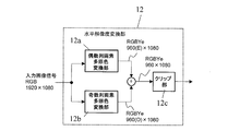
図25に、水平解像度変換部12の具体的な構成の一例を示す。図25に示す水平解像度変換部12は、偶数列画素多原色変換部12aと、奇数列画素多原色変換部12bと、クリップ部12cとを有する。
FIG. 25 shows an example of a specific configuration of the horizontal resolution conversion unit 12. The horizontal resolution conversion unit 12 illustrated in FIG. 25 includes an even column pixel multi-primary color conversion unit 12a, an odd column pixel multi-primary color conversion unit 12b, and a clip unit 12c.
水平解像度変換部12に入力された画像信号は、まず、偶数列の画素に対応する成分と、奇数列の画素に対応する成分とに分離され、偶数列画素多原色変換部12aと、奇数列画素多原色変換部12bとでそれぞれ異なった多原色変換(3色から4色への変換)が行われた後、再合成される。この時点で、水平画素数が1/2になる。
The image signal input to the horizontal resolution conversion unit 12 is first separated into a component corresponding to an even column pixel and a component corresponding to an odd column pixel, and the even column pixel multi-primary color conversion unit 12a and the odd column Different primary color conversions (conversion from three colors to four colors) are performed in the pixel multi-primary color conversion unit 12b, and then recombined. At this point, the number of horizontal pixels is halved.
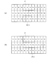
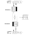
入力画像の偶数列画素と奇数列画素に対する具体的な処理を図26に模式的に示す。図26に示しているように、偶数列の画素は、基本的に赤サブ画素Rおよび緑サブ画素GのサブセットS1により表現されるよう、信号処理が行われる。このとき、入力画像信号の色によってはサブセットS1だけでは表現できないので、サブセットS1に隣接する黄サブ画素Yeおよび青サブ画素Bも補助的に使用される。サブセットS1の少なくとも一部および補助的に使用される黄サブ画素Yeおよび青サブ画素Bが、既に述べたような中間的な「表示単位」として機能する。
FIG. 26 schematically shows specific processing for even-numbered pixels and odd-numbered pixels in the input image. As shown in FIG. 26, the signal processing is performed so that the pixels in the even-numbered columns are basically expressed by the subset S1 of the red sub-pixel R and the green sub-pixel G. At this time, since the color of the input image signal cannot be expressed only by the subset S1, the yellow sub-pixel Ye and the blue sub-pixel B adjacent to the subset S1 are also used supplementarily. At least a part of the subset S1 and the auxiliary yellow subpixel Ye and blue subpixel B function as an intermediate “display unit” as described above.
同様に、奇数列の画素は青サブ画素Bおよび黄サブ画素YeのサブセットS2により表現されるよう、信号処理が行われる。このとき、入力画像信号の色によってはサブセットS2だけでは表現できないので、サブセットS2に隣接する緑サブ画素Gおよび赤サブ画素Rも補助的に使用される。サブセットS2の少なくとも一部および補助的に使用される緑サブ画素Gおよび赤サブ画素Rが、既に述べたような中間的な「表示単位」として機能する。
Similarly, signal processing is performed so that the pixels in the odd-numbered columns are represented by the subset S2 of the blue subpixel B and the yellow subpixel Ye. At this time, since the color of the input image signal cannot be expressed only by the subset S2, the green sub-pixel G and the red sub-pixel R adjacent to the subset S2 are also used supplementarily. At least a part of the subset S2 and the auxiliary green subpixel G and red subpixel R function as an intermediate “display unit” as described above.
このように、もともとの入力画像信号の2画素(偶数列、奇数列)分をそれぞれ1つのサブセットに割り当てるようにする。この処理が行われると、入力画像の3原色信号は偶数列画素、奇数列画素ごとに4種類のサブ画素で表現されることになるので、最後にこれをサブ画素単位で加算合成し、1/2に縮小された4原色画像データを得ることができる。また、補助点灯の量によってはサブ画素単位での加算後にオーバーフローが発生することがあるので、本例では最終段にオーバーフロー対策としてクリップ部12cによるクリッピングを行うが(図25参照)、予めオーバーフローが発生しないように各サブセットへの割り当て時に正規化を行ってもよい。
In this way, two pixels (even columns and odd columns) of the original input image signal are each assigned to one subset. When this processing is performed, the three primary color signals of the input image are expressed by four types of sub-pixels for each of even-numbered column pixels and odd-numbered column pixels. Four primary color image data reduced to / 2 can be obtained. Depending on the amount of auxiliary lighting, overflow may occur after addition in units of sub-pixels. In this example, clipping is performed by the clip unit 12c at the final stage as a countermeasure against overflow (see FIG. 25). Normalization may be performed at the time of assignment to each subset so as not to occur.
上述したように、水平解像度変換部12において、入力画像の偶数列画素がサブセットS1、奇数列画素がサブセットS2で表されるので、表示解像度の2倍の表現が可能になる。本例に照らして言えば、水平方向の画素数が960の液晶表示パネルで1920画素分の解像度表現が可能となる。
As described above, in the horizontal resolution conversion unit 12, the even-numbered pixels of the input image are represented by the subset S1 and the odd-numbered pixels are represented by the subset S2, so that it is possible to express twice the display resolution. In light of this example, a resolution of 1920 pixels can be expressed on a liquid crystal display panel having 960 pixels in the horizontal direction.
図27に、水平解像度変換部12の具体的な構成の他の例を示す。図27に示す水平解像度変換部12は、ローパスフィルタ(LPF)12d、ハイパスフィルタ(HPF)12e、多原色変換部12f、輝度変換部12g、サンプリング部12h、サブ画素レンダリング部12iおよびクリップ部12jを有する。
FIG. 27 shows another example of a specific configuration of the horizontal resolution conversion unit 12. 27 includes a low-pass filter (LPF) 12d, a high-pass filter (HPF) 12e, a multi-primary color conversion unit 12f, a luminance conversion unit 12g, a sampling unit 12h, a sub-pixel rendering unit 12i, and a clip unit 12j. Have.
本例では、入力画像信号は、LPF12dおよびHPF12eにより低域信号と高域信号とに分離されて処理される。LPF12dを通過した低域信号は、多原色変換部12fによって多原色変換(3色から4色への変換)が行われた後、サンプリング部12hにより液晶表示パネル側の解像度でサンプリングされる。この結果得られた信号には高域成分が存在しないので、解像度は劣化しているが色成分は正しく保存されている。
In this example, the input image signal is processed by being separated into a low-frequency signal and a high-frequency signal by the LPF 12d and the HPF 12e. The low-frequency signal that has passed through the LPF 12d is subjected to multi-primary color conversion (conversion from three colors to four colors) by the multi-primary color conversion unit 12f, and then sampled at the resolution on the liquid crystal display panel side by the sampling unit 12h. Since the high frequency component does not exist in the signal obtained as a result, the resolution is deteriorated but the color component is correctly stored.
一方、HPF12eを通過した高域信号は、輝度変換部12gで輝度信号Yに変換された後、サブ画素レンダリング部12iにより、図28に模式的に示しているように、偶数列画素、奇数列画素ごとにサブセットS1およびS2に割り当てられる。赤サブ画素Rおよび緑サブ画素Gにより構成されるサブセットS1は偶数列画素の高域輝度成分を表現するよう点灯制御される。同様に、青サブ画素Bおよび黄サブ画素Yeにより構成されるサブセットS2は奇数列画素の高域輝度成分を表現するよう点灯制御される。これらの信号には入力画像信号の高域成分が保存されている。
On the other hand, the high frequency signal that has passed through the HPF 12e is converted into the luminance signal Y by the luminance conversion unit 12g, and then, by the sub-pixel rendering unit 12i, as shown schematically in FIG. Each pixel is assigned to subsets S1 and S2. The subset S1 composed of the red sub-pixel R and the green sub-pixel G is controlled so as to express the high-frequency luminance component of the even-numbered column pixels. Similarly, the subset S2 composed of the blue sub-pixel B and the yellow sub-pixel Ye is controlled to express the high-frequency luminance component of the odd-numbered column pixels. These signals store the high frequency components of the input image signal.
サブセットS1は、赤サブ画素Rおよび緑サブ画素Gで構成されているので、輝度表現だけでなく色付きが発生することになる。サブセットS2も同様である。しかしながら、人間の視感度は空間周波数が高域の部分では色の分離精度が落ちるので、HPF12eの設計を適切に行い(カットオフ周波数fcを色分離限界の周波数より上に設定することで、色付きとして見えなくなる)、さらにサブセットS1およびS2のそれぞれに隣接するサブ画素を補助的に点灯制御することで、このような問題を回避することができる。
The subset S1 is composed of the red sub-pixel R and the green sub-pixel G, so that not only luminance expression but also coloring occurs. The same applies to the subset S2. However, since the human visual sensitivity is such that the color separation accuracy is lowered in the region where the spatial frequency is high, the HPF 12e is designed appropriately (by setting the cut-off frequency fc above the color separation limit frequency, it is colored). In addition, such a problem can be avoided by additionally controlling lighting of the sub-pixels adjacent to each of the subsets S1 and S2.
最後に、高域成分は含まないものの色成分が保存されている低域成分信号と、サブセットS1およびS2に割り当てられた高域成分信号を加算することで、水平方向について1/2の画素数の液晶表示パネルに、色・解像度とも保存された入力信号を再現することができる。クリップ部12jの動作、目的は、図25に示す例と同様である。
Finally, by adding the low-frequency component signal that does not include the high-frequency component but stores the color component and the high-frequency component signal assigned to the subsets S1 and S2, the number of pixels is halved in the horizontal direction. It is possible to reproduce input signals stored in both color and resolution on the LCD panel. The operation and purpose of the clip unit 12j are the same as in the example shown in FIG.