WO2011093306A1 - 超音波モータ用振動子 - Google Patents
超音波モータ用振動子 Download PDFInfo
- Publication number
- WO2011093306A1 WO2011093306A1 PCT/JP2011/051417 JP2011051417W WO2011093306A1 WO 2011093306 A1 WO2011093306 A1 WO 2011093306A1 JP 2011051417 W JP2011051417 W JP 2011051417W WO 2011093306 A1 WO2011093306 A1 WO 2011093306A1
- Authority
- WO
- WIPO (PCT)
- Prior art keywords
- electrode
- vibration
- vibrator
- bending
- area
- Prior art date
- Legal status (The legal status is an assumption and is not a legal conclusion. Google has not performed a legal analysis and makes no representation as to the accuracy of the status listed.)
- Ceased
Links
Images

Classifications
-
- H—ELECTRICITY
- H10—SEMICONDUCTOR DEVICES; ELECTRIC SOLID-STATE DEVICES NOT OTHERWISE PROVIDED FOR
- H10N—ELECTRIC SOLID-STATE DEVICES NOT OTHERWISE PROVIDED FOR
- H10N30/00—Piezoelectric or electrostrictive devices
- H10N30/20—Piezoelectric or electrostrictive devices with electrical input and mechanical output, e.g. functioning as actuators or vibrators
- H10N30/202—Piezoelectric or electrostrictive devices with electrical input and mechanical output, e.g. functioning as actuators or vibrators using longitudinal or thickness displacement combined with bending, shear or torsion displacement
- H10N30/2023—Piezoelectric or electrostrictive devices with electrical input and mechanical output, e.g. functioning as actuators or vibrators using longitudinal or thickness displacement combined with bending, shear or torsion displacement having polygonal or rectangular shape
-
- H—ELECTRICITY
- H02—GENERATION; CONVERSION OR DISTRIBUTION OF ELECTRIC POWER
- H02N—ELECTRIC MACHINES NOT OTHERWISE PROVIDED FOR
- H02N2/00—Electric machines in general using piezoelectric effect, electrostriction or magnetostriction
- H02N2/0005—Electric machines in general using piezoelectric effect, electrostriction or magnetostriction producing non-specific motion; Details common to machines covered by H02N2/02 - H02N2/16
- H02N2/001—Driving devices, e.g. vibrators
- H02N2/003—Driving devices, e.g. vibrators using longitudinal or radial modes combined with bending modes
- H02N2/004—Rectangular vibrators
-
- H—ELECTRICITY
- H10—SEMICONDUCTOR DEVICES; ELECTRIC SOLID-STATE DEVICES NOT OTHERWISE PROVIDED FOR
- H10N—ELECTRIC SOLID-STATE DEVICES NOT OTHERWISE PROVIDED FOR
- H10N30/00—Piezoelectric or electrostrictive devices
- H10N30/80—Constructional details
- H10N30/87—Electrodes or interconnections, e.g. leads or terminals
Definitions
- the present invention relates to a vibrator for an ultrasonic motor, and more particularly to a vibrator for an ultrasonic motor in which electrodes on a piezoelectric vibration element are arranged independently in the polarization regions of bending vibration and stretching vibration.
- This ultrasonic motor is a driving device based on a driving principle that is completely different from that of an electromagnetic motor, and has excellent features such as low speed, high torque, silence, and retention when stopped. Further, since the structure of the vibrator is simple, it is advantageous for downsizing and is expected as a small actuator.
- an ultrasonic motor is composed of a vibrator and a moving body, and functions in a state where the frictional contact portion of the vibrator is pressed against the moving body and pressurized. In this state, an elliptical motion is generated in the frictional contact portion of the vibrator, so that the frictional contact portion intermittently presses the moving body and sends the moving body in one direction.
- the moving speed of the moving body is controlled by changing the amplitude of the elliptical motion.
- the speed of the moving body driven by the vibrator is controlled by changing the amplitude of the elliptical motion of the frictional contact portion at the tip of the vibrator.
- the trajectory shape of this elliptical motion cannot be changed arbitrarily with a normal ultrasonic motor, the amplitude of the elliptical motion becomes smaller overall when driven at a low speed, and the addition of a vibrator that controls the frictional force.
- the vibration component in the pressure direction also becomes small, and the operation becomes unstable and stops.
- the input / output characteristics of the speed are nonlinear and there is a dead zone. With such input / output characteristics, it is difficult to perform stable speed control in a low speed range, so that accuracy and resolution performance as a motor are degraded.
- an electrode region for exciting bending vibration and an electrode region for exciting stretching vibration are arranged in all the piezoelectric elements to be laminated, and each vibration is made independent. Can be controlled. According to this, the magnitude of the bending vibration and the stretching vibration that generate the elliptical motion and the phase difference thereof can be freely adjusted individually, and sufficient vibration in the pressing direction can be obtained even in the low speed range. Non-linearity and dead zone can be eliminated.
- the vibrator for an ultrasonic motor shown in Patent Document 1 has a rectangular plate shape, and its electrode shape is also rectangular or cross-shaped.
- both the piezoelectric element and the electrode are rectangular. .
- the electrode cannot be appropriately disposed at a location where the strain distribution is large, and the loss of vibration efficiency of the vibrator becomes large. This loss of vibration efficiency leads to heat generation and temperature rise of the vibrator, which adversely affects stability and reliability.
- stress concentration occurs at the corners when a voltage is applied, causing repeated stress due to vibration, causing fatigue cracks and breakage, which reduces the reliability and durability of the vibrator. There was a problem of being connected.
- the present invention provides an ultrasonic motor vibrator that solves such problems, in particular, reduces the loss of the vibrator (increases the vibration efficiency) and improves the durability and reliability of the vibrator.
- the issue is to provide.
- an ultrasonic motor vibrator characterized in that an electrode including a curved portion is arranged in an outer shape in a region where the distortion of the natural vibration mode of a rectangular plate-shaped piezoelectric vibration element is large.
- an electrode for exciting bending vibration and an electrode for exciting stretching vibration are provided separately.
- a vibrator for a sonic motor is provided.
- the ultrasonic motor vibrator according to (2) wherein (3) the bending vibration is a bending secondary vibration and the stretching vibration is a stretching primary stretching.
- the electrode that excites the bending vibration has a region in which the distortion of the bending natural vibration mode is equal to or greater than a predetermined value, and the outer curve portion of the electrode substantially extends on the contour line of the distortion.
- the vibrator for ultrasonic motors according to (2) or (3), which is disposed along, is provided.
- the vibrator for ultrasonic motors described in 1) is provided.
- the electrode for exciting the stretching vibration has an outline curve portion of the electrode substantially along a strain contour line in a region where the strain in the stretching natural vibration mode is a predetermined value or more.
- the ultrasonic motor vibrator according to (2), which is disposed, is provided.
- the area of the electrode for exciting the stretching vibration is 15% or more and 45% or less of the total area of the piezoelectric vibration element, (2), (3) or (6 ) Is provided.
- the bending vibration electrode and the stretching vibration electrode interfere with each other, either the bending vibration electrode or the stretching vibration electrode is provided at the position of the interference.
- the electrode is arranged so that the outer curve portion is substantially along the contour line of the strain, the other electrode is arranged with a gap between the outer portion of the one electrode, and the two electrodes are insulated from each other.
- the ultrasonic motor vibrator according to any one of (4) to (7) is provided.
- the electrode area for bending vibration is 40% of the total area of the vibrator.
- the strain value is a region where the maximum value of strain is normalized by 1 and is 0.23 or more
- the electrode area for bending vibration is 15% of the total area of the vibrator, 0.47 or more
- the ultrasonic motor transducer according to (4) or (5), which is a region, is provided.
- the region where the distortion in the expansion / contraction natural vibration mode is a predetermined value or more, when the electrode area for expansion / contraction vibration is 45% of the total area of the vibrator,
- the strain value is a region where the maximum value of strain is normalized by 1 and is 0.75 or more, and the electrode area for stretching vibration is 15% of the total area of the vibrator, 0.95 or more
- the ultrasonic motor transducer according to (6) or (7) which is a region of the above, is provided.
- the present invention in an ultrasonic motor vibrator, it is possible to reduce vibrator loss that causes a rise in temperature of the vibrator and heat generation.
- part of the outer shape of the electrode has a shape that includes a curved portion substantially along the contour line of the strain, the stress of the vibrator that occurs when voltage is applied is reduced, and fatigue cracks and breakage due to stress concentration are eliminated. Durability and reliability are improved.
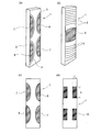
- FIG. 1 It is a top view of the vibrator for ultrasonic motors concerning the example of the present invention.
- A is the perspective view which showed the distortion distribution of the bending secondary natural vibration mode at the time of the voltage application of a vibrator
- (b) is the expansion-contraction primary at the time of the same voltage application of a vibrator
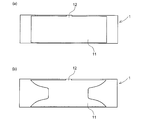
- FIG. 6A is a plan view of an embodiment of the present invention in which a ground electrode is formed on one side of a piezoelectric element.
- FIG. 6A shows a case where a rectangular ground electrode is provided on one side of the element. Is a case where a ground electrode having an outer shape partially along the curved surface of the bending electrode for bending vibration is provided.
- the piezoelectric vibration element has an electrode structure capable of exciting the bending natural vibration mode and the expansion / contraction natural vibration mode independently.
- an electrode having a curved shape in which a part of the outer shape is along the contour line of the distortion is substantially along the contour line of the distortion in a region where the distortion in each natural vibration mode is large.
- FIG. 1 is a plan view of an ultrasonic motor vibrator according to an embodiment of the present invention
- FIG. 2A is a model of a strain distribution of a bending secondary natural vibration mode when a voltage is applied to the vibrator in a striped pattern
- FIG. 2B is a perspective view schematically showing the stretching strain distribution in the stretching primary natural vibration mode.
- the amplitude distribution is a lateral vibration (vibration having an amplitude in the element plane) in which the entire length of the rectangular plate-like piezoelectric element 1 corresponds to approximately one wavelength.
- the total length of the rectangular plate-like piezoelectric element 1 is a longitudinal vibration corresponding to a half wavelength (a vibration having an amplitude in the longitudinal direction of the element), and a bending vibration.
- the distortion becomes the maximum at the place where the vibration displacement is the minimum.
- the strain becomes maximum near the center of the rectangular plate-shaped piezoelectric element 1, and the strain is distributed in a substantially concentric manner from this position toward the free end side.
- 5 and 6 are contour lines in the expansion and contraction primary vibration.
- the electrodes 7 and 8 that cause the bending vibration are disposed at a position where the distortion is maximum and are disposed one by one so as to face each other in the lateral width direction when viewed on one side of the rectangular plate-like piezoelectric element 1.
- a pair is also arranged on the other surface (the back surface in the figure) in a similar relationship. That is, the arrangement form of the bending vibration electrodes 7 and 8 is two pairs on each side of the element 1.
- the electrodes 9 are arranged one on each of the opposing front and back surfaces of the central position in the longitudinal direction of the rectangular plate-like piezoelectric element 1.
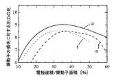
- FIG. 3 is a diagram showing the output ratio (vertical axis in the figure) with respect to the loss of the vibrator when the electrode area / vibrator area (horizontal axis) is changed. The larger the output ratio, the smaller the loss of the vibrator. .
- FIG. 3 is a diagram showing the output ratio (vertical axis in the figure) with respect to the loss of the vibrator when the electrode area / vibrator area (horizontal axis) is changed. The larger the output ratio, the smaller the loss of the vibrator. .
- reference symbol a denotes the vibrator 1 of the present invention in which the bending secondary vibration electrodes 7 and 8 are formed on the basis of the strain reference of the electrodes arranged substantially along the contour line of the strain in the natural vibration mode (FIG. 3C).
- the output electrode is not shown in the figure.
- e is the output ratio when the electrode length s is changed in the vibrator 1 (FIG. (D)) (the extendable electrode is not shown) provided with the conventional rectangular plate electrode 10
- f is the rectangular plate electrode. This is the output ratio when the electrode width t of 10 is changed.
- the electrode shape of the present invention arranged in a region where the strain is greater than or equal to a predetermined value has a larger total electrode area / area than the conventional rectangular plate electrode 10.
- the shape of the electrode formed on the basis of the magnitude of strain of the present invention is excellent because it exceeds the vibrator area. Moreover, it can be seen from the results of FIG.
- the electrode area showing the maximum varies depending on the value of the equivalent load resistance of the frictional contact portion (the tip of the vibrator), but in the bending secondary vibration, it is 40% or less of the total area of the vibrator at the maximum. It is 45% or less of the total area of the vibrator, preferably 40% or less.
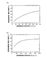
- FIG. 4 shows the relationship between the equivalent load resistance [N / (m / s)] of the friction contact portion and the optimum electrode area / vibrator area (%).
- (A) is the case of the expansion and contraction primary vibration electrode
- (b) is the case of the bending secondary vibration electrode.
- the optimum electrode area / vibrator area (%) varies somewhat depending on the load resistance of the frictional contact portion.
- the electrode area of the vibrator is 15% of the total area of the vibrator. % To 40% is reasonable.
- the graph of FIG. 3 is a result when an equivalent load resistance is about 300 N / (m / s). Although it is assumed that the practical equivalent load resistance varies slightly depending on the configuration of the motor, it is about 50 N / (m / s) for the expansion / contraction primary vibration and about 300 N / (m / s) for the bending secondary vibration. .
- the electrode area is less than 15%, the electromechanical conversion efficiency for converting electrical energy into mechanical energy is reduced, and the dielectric loss ratio of the vibrator is increased. Conversely, when the electrode area exceeds 40%. The ratio of loss due to vibration and mechanical loss increases due to a decrease in the Q value of the vibrator.
- the bending vibration electrode and the stretching vibration electrode are arranged in a region where the strain becomes a predetermined value or more.
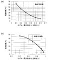
- the predetermined value in this case varies depending on the area of the arranged electrode. For example, in the case of bending secondary vibration, if the maximum strain value is normalized by 1, the predetermined value is 0.47 or more when the electrode area is 15% of the total area of the element, and the predetermined value is obtained when the electrode area is 40%. The value is 0.23 or more. Therefore, the electrodes are arranged in the region where the strain value is 0.23 to 0.47 or more in the vibration in which the electrode area is set to 40% to 15%.
- an electrode is arranged in a region where the strain value is 0.95 or more when the electrode area is 15%, and the strain value is 0.75 or more when the electrode area is 45%
- the electrode is arranged in the region of (when the maximum value is normalized by 1).
- FIG. 5 is a diagram showing the relationship between strain and electrode area.
- A shows the electrode area (%) with respect to the value of strain ⁇ in the case of bending secondary vibration, and (b) shows the expansion and contraction primary vibration.
- the electrode area (%) with respect to the value of the strain ⁇ in the case is shown (the strain is normalized by 1 at the maximum value).
- the electrode arrangement structure of the ultrasonic motor transducer of the embodiment shown in FIG. 1 will be specifically described.
- the bending secondary vibration electrodes 7 and 8 have outer edges 7a and 8a adjacent to the long side portion 1a of the rectangular plate-like piezoelectric element 1 in parallel, and the inner edges 7b and 8b have the above-described predetermined distortion. It is formed in a curved shape along the contour line, and is arranged in a form of two pairs on each surface (two pairs each facing the front surface and the back surface), and on the surface of the piezoelectric element 1, the long side portion 1a of FIG. Connection portions 7c and 8c with external electrodes (not shown) are formed at the positions.
- the electrode on the back surface of the piezoelectric element 1 is connected to an external electrode (not shown) different from the external electrode connected to the front surface side.
- the secondary bending vibration is excited by driving the electrodes 7 and 8 paired on each surface in opposite phases.
- the electrode area for the secondary bending vibration is 34% of the total area of the vibrator. Therefore, the distortion contour line of the element surface that gives the electrode curve portion is selected as a distortion area of about 0.25 or more. (See FIG. 5 (a)).
- the rectangular plate-like piezoelectric element 1 is disposed at the same central position on the front and back surfaces, and on the front side, the electrode outer side portion 9 a is adjacent to the long side portion 1 a of the element 1, and A connection portion 9c to the external electrode is formed on the other long side portion 1b of the element 1.
- the electrode outer side portion is connected to another external electrode at the long side portion 1 a of the element 1, and the other long side side portion 1 b of the element 1 is back side Adjacent the electrodes.
- the expansion and contraction primary vibration electrode is also basically arranged so as to substantially extend along the contour line of the expansion and contraction strain of a predetermined value or more. Select an area where the distortion of the stretching vibration is as high as possible.
- the expansion / contraction primary vibration electrode 9 is spaced from the bending secondary vibration electrodes 7 and 8 by a distance d so that sufficient insulation is ensured, and the bending vibration electrodes 7 and 8. It forms and arranges in the shape of a curve along the curved shape portion.
- the area of the stretching vibration electrode 9 is about 20% of the total area of the vibrator. In this case, the insulation between the electrodes d for the bending vibrator and the stretching vibration is ensured by a gap of 0.2 to 0.5 mm.
- the stretching vibration electrode 9 is preferentially disposed so that both ends in the longitudinal direction of the stretching vibration electrode 9 are substantially along the contour lines of the stretching strain, and the bending vibration electrodes 7 and 8 are stretched. You may make it adjoin with the clearance gap which can ensure sufficient insulation with respect to the electrode 9 for an object.
- the electrode for bending vibration and the electrode for stretching vibration are provided on both the front and back surfaces of the rectangular plate-like piezoelectric element.
- the back surface of the piezoelectric element 1 is not provided with electrodes for bending vibration and stretching vibration.
- a common ground electrode 11 is formed for both electrodes on the surface, and this is connected to an external ground electrode (not shown). You may make it connect to.
- the ground electrode 11 has a shape and a size that can cover the electrode positions for bending vibration and stretching vibration on the opposite surface of the element.
- FIG. 6 (a) shows a case where a rectangular ground electrode is provided on one surface of the element
- FIG. 6 (b) shows an external ground electrode partially along the curved surface of the bending electrode for bending vibration. This is the case.
- Reference numeral 12 denotes a connection portion with an external earth electrode provided on the ground electrode 11.
- the vibrator electrode according to the present invention has a curved portion for both bending vibration and stretching vibration. Therefore, unlike the conventional rectangular or cross-shaped electrode, the vibrator electrode is accompanied by vibration at a corner. Stress concentration is suppressed, and cracks and breakage due to repeated stress are prevented. In particular, since a high stress is generated between the bending vibration electrode and the stretching vibration electrode, if the electrode is a smooth curve between the electrodes as in the vibrator according to the present invention, it is difficult for stress concentration to occur, and durability. It becomes a vibrator for ultrasonic motors with excellent reliability and reliability. Since the electrode has a curved shape along the contour line of the strain, there are many advantages such that the electrode can be optimally arranged at a location where the strain distribution is large and the loss of the vibrator can be minimized.
- the electrode shape of the vibrator follows the strain contour line in a region where the distortion of the natural vibration mode is large. Any other vibration mode may be used as long as the piezoelectric vibrator has a rectangular plate shape in which electrodes having a shape including a curved line are arranged.
- the absolute value of the amplitude is generally small, and it becomes difficult to excite the stretching vibration and the bending vibration independently, and the electrode arrangement is complicated, so that the stretching primary vibration and the bending secondary vibration are complicated. It is preferable to apply to a vibrator combined with vibration.
Landscapes
- General Electrical Machinery Utilizing Piezoelectricity, Electrostriction Or Magnetostriction (AREA)
Priority Applications (3)
| Application Number | Priority Date | Filing Date | Title |
|---|---|---|---|
| CN201180007460.1A CN102725951B (zh) | 2010-01-27 | 2011-01-26 | 超声波电动机用振子 |
| US13/575,544 US9099640B2 (en) | 2010-01-27 | 2011-01-26 | Transducer for ultrasonic motor |
| EP11737019.7A EP2530825A4 (en) | 2010-01-27 | 2011-01-26 | CONVERTER FOR AN ULTRASOUND MOTOR |
Applications Claiming Priority (2)
| Application Number | Priority Date | Filing Date | Title |
|---|---|---|---|
| JP2010015216A JP4830165B2 (ja) | 2010-01-27 | 2010-01-27 | 超音波モータ用振動子 |
| JP2010-015216 | 2010-01-27 |
Publications (1)
| Publication Number | Publication Date |
|---|---|
| WO2011093306A1 true WO2011093306A1 (ja) | 2011-08-04 |
Family
ID=44319293
Family Applications (1)
| Application Number | Title | Priority Date | Filing Date |
|---|---|---|---|
| PCT/JP2011/051417 Ceased WO2011093306A1 (ja) | 2010-01-27 | 2011-01-26 | 超音波モータ用振動子 |
Country Status (5)
| Country | Link |
|---|---|
| US (1) | US9099640B2 (enExample) |
| EP (1) | EP2530825A4 (enExample) |
| JP (1) | JP4830165B2 (enExample) |
| CN (1) | CN102725951B (enExample) |
| WO (1) | WO2011093306A1 (enExample) |
Cited By (1)
| Publication number | Priority date | Publication date | Assignee | Title |
|---|---|---|---|---|
| US10063163B2 (en) | 2012-06-15 | 2018-08-28 | Commissariat A L'energie Atomique Et Aux Energies Alternatives | Actuator for an ultrasonic motor and ultrasonic motor comprising at least one such actuator |
Families Citing this family (5)
| Publication number | Priority date | Publication date | Assignee | Title |
|---|---|---|---|---|
| JP6367693B2 (ja) * | 2014-11-21 | 2018-08-01 | 京セラ株式会社 | 圧電素子、圧電振動装置、音響発生器、音響発生装置および電子機器 |
| WO2017065263A1 (ja) * | 2015-10-15 | 2017-04-20 | 有限会社Uwave | ランジュバン型超音波振動子の振動励起方法及び超音波加工方法と超音波送信方法 |
| US20210367135A1 (en) * | 2017-04-17 | 2021-11-25 | Rda Microelectronics (Shanghai) Co., Ltd. | Mems piezoelectric transducer having optimized capacitor shape |
| CN107359810B (zh) * | 2017-08-17 | 2023-04-25 | 浙江师范大学 | 一种超低频压电振动俘能器 |
| US12329033B2 (en) * | 2021-10-21 | 2025-06-10 | Skyworks Solutions, Inc. | Piezoelectric sensor with increased sensitivity and devices having the same |
Citations (6)
| Publication number | Priority date | Publication date | Assignee | Title |
|---|---|---|---|---|
| JP3311446B2 (ja) | 1993-11-30 | 2002-08-05 | オリンパス光学工業株式会社 | 超音波モータ |
| JP2004297951A (ja) | 2003-03-27 | 2004-10-21 | Olympus Corp | 超音波振動子及び超音波モータ |
| JP2007028862A (ja) * | 2005-07-21 | 2007-02-01 | Seiko Epson Corp | 圧電アクチュエータ、および電子機器 |
| JP2008054407A (ja) | 2006-08-24 | 2008-03-06 | Nikko Co | 超音波モータ用振動子 |
| JP2009284759A (ja) * | 2009-08-31 | 2009-12-03 | Seiko Instruments Inc | 超音波モータ及び超音波モータ付き電子機器 |
| JP2010004625A (ja) * | 2008-06-19 | 2010-01-07 | Nec Tokin Corp | 圧電振動子およびその駆動方法 |
Family Cites Families (4)
| Publication number | Priority date | Publication date | Assignee | Title |
|---|---|---|---|---|
| JP2722211B2 (ja) * | 1988-07-30 | 1998-03-04 | 本多電子株式会社 | 超音波駆動装置 |
| EP1186063B1 (en) * | 1999-05-31 | 2006-07-12 | Nanomotion Ltd. | Multilayer piezoelectric motor |
| JP4679938B2 (ja) * | 2005-03-11 | 2011-05-11 | オリンパス株式会社 | 超音波モータ |
| CN101213734B (zh) * | 2006-02-07 | 2011-01-12 | 松下电器产业株式会社 | 压电元件与超声波执行机构 |
-
2010
- 2010-01-27 JP JP2010015216A patent/JP4830165B2/ja active Active
-
2011
- 2011-01-26 CN CN201180007460.1A patent/CN102725951B/zh not_active Expired - Fee Related
- 2011-01-26 WO PCT/JP2011/051417 patent/WO2011093306A1/ja not_active Ceased
- 2011-01-26 EP EP11737019.7A patent/EP2530825A4/en not_active Withdrawn
- 2011-01-26 US US13/575,544 patent/US9099640B2/en not_active Expired - Fee Related
Patent Citations (6)
| Publication number | Priority date | Publication date | Assignee | Title |
|---|---|---|---|---|
| JP3311446B2 (ja) | 1993-11-30 | 2002-08-05 | オリンパス光学工業株式会社 | 超音波モータ |
| JP2004297951A (ja) | 2003-03-27 | 2004-10-21 | Olympus Corp | 超音波振動子及び超音波モータ |
| JP2007028862A (ja) * | 2005-07-21 | 2007-02-01 | Seiko Epson Corp | 圧電アクチュエータ、および電子機器 |
| JP2008054407A (ja) | 2006-08-24 | 2008-03-06 | Nikko Co | 超音波モータ用振動子 |
| JP2010004625A (ja) * | 2008-06-19 | 2010-01-07 | Nec Tokin Corp | 圧電振動子およびその駆動方法 |
| JP2009284759A (ja) * | 2009-08-31 | 2009-12-03 | Seiko Instruments Inc | 超音波モータ及び超音波モータ付き電子機器 |
Non-Patent Citations (1)
| Title |
|---|
| See also references of EP2530825A4 |
Cited By (1)
| Publication number | Priority date | Publication date | Assignee | Title |
|---|---|---|---|---|
| US10063163B2 (en) | 2012-06-15 | 2018-08-28 | Commissariat A L'energie Atomique Et Aux Energies Alternatives | Actuator for an ultrasonic motor and ultrasonic motor comprising at least one such actuator |
Also Published As
| Publication number | Publication date |
|---|---|
| EP2530825A1 (en) | 2012-12-05 |
| US9099640B2 (en) | 2015-08-04 |
| JP2011155760A (ja) | 2011-08-11 |
| CN102725951A (zh) | 2012-10-10 |
| JP4830165B2 (ja) | 2011-12-07 |
| EP2530825A4 (en) | 2015-04-08 |
| US20120293043A1 (en) | 2012-11-22 |
| CN102725951B (zh) | 2015-08-19 |
Similar Documents
| Publication | Publication Date | Title |
|---|---|---|
| JP4830165B2 (ja) | 超音波モータ用振動子 | |
| JP4289511B2 (ja) | 圧電アクチュエータ | |
| CN103259449B (zh) | 压电驱动器及压电马达 | |
| CN101626203A (zh) | 弯振模态梁式直线超声电机振子 | |
| US20090278421A1 (en) | Ultrasonic motor | |
| CN109347362B (zh) | 基于压电陶瓷扭转振动模式的异向双动子驻波型直线超声波电机 | |
| CN117134650A (zh) | 基于千足虫仿生运动的贴片式超声作动器及其控制方法 | |
| Liu et al. | A novel plate type linear piezoelectric actuator using dual-frequency drive | |
| JPH0661542A (ja) | 異方性トランスデューサ | |
| CN104883090A (zh) | 融合切变压电致动器复合驱动模式的压电直线马达 | |
| US11043908B2 (en) | Ultrasonic motor having a diagonally excitable actuator plate | |
| CN102569637B (zh) | 压电驱动器及压电马达 | |
| CN101119079A (zh) | 三角形弯板式压电直线超声电机 | |
| CN102810997B (zh) | 减摩驱动式超声电机及其复合式定子组件 | |
| CN102497131B (zh) | 一种直线式超声电机的作动器 | |
| JPS60200776A (ja) | 駆動装置 | |
| CN104124891A (zh) | 压电振子及包括该压电振子的精密位移平台 | |
| CN109302096B (zh) | 基于十字型定子结构的多陶瓷激振驻波型直线超声波电机 | |
| JP4892661B2 (ja) | 超音波モータ用振動子 | |
| CN106953540A (zh) | 压电振子、包括该压电振子的驱动器及微动台 | |
| CN101162875B (zh) | 细直径活塞式压电直线电机 | |
| US20020014812A1 (en) | Actuator using a piezoelectric element | |
| CN112072951A (zh) | A型弹性拓扑压电致动机构 | |
| CN101689817B (zh) | 超声波电动机 | |
| JP2015144557A (ja) | 超音波モータの駆動制御方法及び超音波モータの駆動制御装置 |
Legal Events
| Date | Code | Title | Description |
|---|---|---|---|
| WWE | Wipo information: entry into national phase |
Ref document number: 201180007460.1 Country of ref document: CN |
|
| 121 | Ep: the epo has been informed by wipo that ep was designated in this application |
Ref document number: 11737019 Country of ref document: EP Kind code of ref document: A1 |
|
| WWE | Wipo information: entry into national phase |
Ref document number: 13575544 Country of ref document: US |
|
| NENP | Non-entry into the national phase |
Ref country code: DE |
|
| REEP | Request for entry into the european phase |
Ref document number: 2011737019 Country of ref document: EP |
|
| WWE | Wipo information: entry into national phase |
Ref document number: 2011737019 Country of ref document: EP |