WO2011090041A1 - 振動受粉装置 - Google Patents
振動受粉装置 Download PDFInfo
- Publication number
- WO2011090041A1 WO2011090041A1 PCT/JP2011/050807 JP2011050807W WO2011090041A1 WO 2011090041 A1 WO2011090041 A1 WO 2011090041A1 JP 2011050807 W JP2011050807 W JP 2011050807W WO 2011090041 A1 WO2011090041 A1 WO 2011090041A1
- Authority
- WO
- WIPO (PCT)
- Prior art keywords
- vibration
- pollination
- plant
- sensor
- pollination apparatus
- Prior art date
- Legal status (The legal status is an assumption and is not a legal conclusion. Google has not performed a legal analysis and makes no representation as to the accuracy of the status listed.)
- Ceased
Links
Images




Classifications
-
- A—HUMAN NECESSITIES
- A01—AGRICULTURE; FORESTRY; ANIMAL HUSBANDRY; HUNTING; TRAPPING; FISHING
- A01H—NEW PLANTS OR NON-TRANSGENIC PROCESSES FOR OBTAINING THEM; PLANT REPRODUCTION BY TISSUE CULTURE TECHNIQUES
- A01H1/00—Processes for modifying genotypes ; Plants characterised by associated natural traits
- A01H1/02—Methods or apparatus for hybridisation; Artificial pollination ; Fertility
- A01H1/027—Apparatus for pollination
Definitions
- the present invention relates to a vibration pollination apparatus having a vibration means for applying vibration to a plant and a drive means for driving the vibration means.
- a vibration pollination apparatus in which a plant is vibrated by a vibration means to disperse pollen and adhere to the stigma of a flower pistil.
- These vibration pollination devices are made by bringing a hand-held vibration means directly into contact with a plant to give vibration, or fixing a wire or the like to a plant and giving vibration to the wire to give the plant vibration (for example, (See Patent Documents 1 and 2).
- JP-A-7-289105 (all pages, all figures) JP 2002-112653 A (all pages, all figures)
- the former hand-held vibration means can be used for direct contact with each strain of plants during artificial pollination. According to the work that occurs and the latter wire is fixed to the plant, the work for directly fixing the wire to each strain of the plant occurs, which is troublesome and inefficient. It was.
- the present invention solves the problems of the prior art as described above, that is, the object of the present invention is to simplify the work for artificial pollination and improve the efficiency without damaging the plant. It is to provide a pollination device.
- the invention according to claim 1 is a vibration pollination apparatus having a vibration means for applying vibration to a plant and a drive means for driving the vibration means, wherein the vibration means does not directly contact the plant and vibrates air.
- the electromagnetic actuator for applying vibration to the diaphragm, and the driving means includes drive signal generating means for driving the electromagnetic actuator by an electric signal. Is.
- the invention according to claim 2 further solves the problem by providing the vibration means in a movable carriage in addition to the configuration of the vibration pollination apparatus described in claim 1. It is.
- the invention according to claim 3 is a direction in which, in addition to the configuration of the vibration pollination apparatus according to claim 1 or 2, the direction in which the excitation means generates air vibration of the diaphragm is variable. Having the changing means further solves the above problem.
- the driving means processes an environment sensor and a signal of the environment sensor.
- the present invention further solves the above problems by having a control means for controlling at least one of the drive signal generating means, the direction changing means and the movement of the carriage.
- the invention according to claim 5 further includes the above-described problem by providing the environmental sensor in a cart that can move together with the vibration means. It is a solution.
- the environmental sensor includes an imaging unit, and the control unit is configured to control a plant by the imaging unit.
- the problem is further solved by determining the position of the flower and controlling at least one of the direction changing means and the movement of the carriage.
- the environmental sensor includes a temperature sensor and a humidity sensor
- the control unit includes: The problem is further solved by determining the optimum amplitude and frequency for pollination of plants by the temperature sensor and the humidity sensor and controlling the drive signal generating means.
- the invention according to claim 8 further provides the above-described problem by providing a plurality of the excitation means. It is a solution.
- the excitation means amplifies the vibration of the diaphragm or increases the directivity.
- the vibration pollination apparatus is a vibration pollination apparatus having a vibration means for applying vibration to a plant and a drive means for driving the vibration means.
- the vibration means does not directly contact the plant.
- the drive means includes drive signal generation means for driving the electromagnetic actuator by an electric signal, so
- the amount of work can be greatly reduced and the efficiency can be improved.
- the vibration pollination apparatus according to the second aspect of the invention has the effect of the vibration pollination apparatus according to the first aspect, in addition to the effects of the vibration pollination apparatus according to the first aspect.
- Artificial pollination can be performed while moving automatically, and efficiency can be improved.
- the vibration pollination device of the invention according to claim 3 is a direction in which the direction in which the vibration generating means generates the air vibration of the diaphragm is variable in addition to the effect exhibited by the vibration pollination device according to claim 1 or claim 2.
- the drive means processes the environmental sensor and the signal of the environmental sensor.
- a control means for controlling at least one of the drive signal generating means, the direction changing means, and the movement of the carriage the optimum vibration according to the state of the plant and the surrounding environment is applied to the optimum position. And the efficiency can be further improved.
- the vibration pollination apparatus vibrates in addition to the effect exhibited by the vibration pollination apparatus according to the fourth aspect of the present invention, because the environmental sensor is provided on a movable carriage together with the vibration means.
- the situation of the plant and the surrounding environment can be detected at a position close to the plant strain to be improved, and the efficiency can be further improved.
- the vibration pollination device of the invention according to claim 6 includes an image sensor, and the control device uses the image sensor to control the plant flower.
- the vibration pollination apparatus is characterized in that, in addition to the effects exhibited by the vibration pollination apparatus according to any one of the fourth to sixth aspects, the environmental sensor includes a temperature sensor and a humidity sensor.
- the environmental sensor includes a temperature sensor and a humidity sensor.
- the drive signal generating means by controlling the drive signal generating means by determining the optimum amplitude and frequency for pollination of plants by the temperature sensor and the humidity sensor, it is possible to apply a more optimal vibration and further improve the efficiency. .
- the vibration pollination device according to the invention according to claim 8 is provided with a plurality of vibration means. It is possible to vibrate the flower of the plant, to improve the excitation force by resonance from a plurality of excitation means, and to increase the work speed and improve the efficiency.
- the vibration means amplifies or directs the vibration of the diaphragm.
- the vibration means amplifies or directs the vibration of the diaphragm.
- the vibration pollination apparatus of the present invention is a vibration pollination apparatus having a vibration means for applying vibration to a plant and a drive means for driving the vibration means, and the vibration means does not directly contact the plant and generates air vibration.
- a vibration plate and an electromagnetic actuator that vibrates the vibration plate are provided, and the drive means includes drive signal generation means for driving the electromagnetic actuator by an electric signal, simplifying the work for artificial pollination and damaging the plant As long as the efficiency is improved, any specific embodiment may be used.
- the vibration pollination apparatus of the present invention can be provided in the vicinity of any plant as long as it is provided in the vicinity of the plant to be cultivated, and in any environment such as an alley, a house, or a building. good.
- the diaphragm and the electromagnetic actuator used in the vibration pollination apparatus of the present invention may have any shape as long as the diaphragm can generate air vibration, and may be a general so-called speaker unit. .
- the vibration pollination apparatus 100 of the present invention includes a vibration means 110 that generates air vibration without directly contacting the plant P, and a drive means 120 that drives the vibration means 110.
- the plant P is configured to indirectly give vibration to the flower F by air vibration.
- the vibration means 110 includes a vibration plate 111 that generates air vibration and an electromagnetic actuator 112 that applies vibration to the vibration plate 111.
- the driving means 120 includes a drive signal generation means 121, and the electromagnetic actuator 112 is a drive signal generation means. When driven by the electrical signal from 121, the diaphragm 111 vibrates and air vibrations are generated.
- the vibration means 110 may be provided with a reflecting plate 113 at a position facing the plant P so as to more efficiently apply air vibration to the plant P.
- the two diaphragms 111a and 111b and the electromagnetic actuators 112a and 112b may be simultaneously driven in opposite directions to simultaneously apply vibrations to plants in both directions.
- the two diaphragms 111a and 111b and the electromagnetic actuators 112a and 112b may be directed to the same plant P so that the excitation force at the intersection of the directing directions increases. .
- the vibration pollination apparatus 200 is provided with a vibration means 210 that generates air vibration without directly contacting a plurality of plants P and is fixed to a fixed base 230.
- the reflection plate 213 is provided at a position opposite to the plant P, and the vibration unit 210 is driven by the driving unit 220 during artificial pollination to generate air vibrations. It is configured to give vibration.
- the air vibration generated from the exciting means 210 is set to an amplitude and frequency at which the flower of the plant P effectively vibrates, and pollen is scattered by the vibration and reliably fertilized by adhering to the stigma of the flower pistil To make it fruit.
- artificial pollination can be performed only by installing the vibration means 210 on the fixed base 230, the operation is simplified, and work efficiency can be improved without damaging the plant.
- the reflecting plate 213 at a position facing the plant P, the excitation force for vibrating the plant P is improved, and noise leakage to the surroundings due to air vibration is reduced.
- the vibration pollination apparatus 300 is provided with a vibration means 310 that generates air vibration without directly contacting a plurality of plants P and is fixed to the traveling carriage 331.
- the traveling carriage 331 is configured to be movable on a traveling rail 332 provided along the side of the row of the plurality of plants P.
- the vibration means 310 is driven to generate air vibration, and the plant P flower is indirectly subjected to vibration by air vibration.
- the amplitude of the air vibration generated from the vibration means 310, the frequency, and the moving speed of the traveling carriage 331 are set so that the flower of the plant P is vibrated effectively.
- fertilization can be ensured and fruiting can be achieved.
- the traveling rail 332 it is possible to run the traveling carriage 331 for all plants to perform artificial pollination, and the work is simplified. The work efficiency can be improved without damaging the plant.
- the vibration means 310 can pass in the immediate vicinity of the plant P, an air vibration is effectively transmitted by the flower of the plant P, and it can fertilize more reliably and it can make it fruit.
- a plurality of vibration means 310 are arranged in the traveling direction, and this makes it possible to simultaneously vibrate plants present in a wide range, so that the traveling speed of the traveling carriage 331 can be improved. And work efficiency is further improved.
- the plurality of excitation means 310 may be arranged so that the excitation force at the intersection in the directivity direction increases as in the arrangement example described above.
- the vibration pollination apparatus 400 is provided with vibration means 410 that generates air vibration without directly contacting a plurality of plants P and is fixed to the traveling carriage 431.
- the traveling carriage 431 is configured to be movable on a traveling rail 432 provided along the side of the row of the plurality of plants P.
- the traveling carriage 431 is provided with an environmental sensor 422 such as an imaging means, a temperature sensor, and a humidity sensor, and is configured to detect environmental information in the vicinity of the position of the traveling carriage 431.
- the drive means 420 receives the environmental information detected by the environmental sensor 422 and controls the drive signal generation means 421, whereby the amplitude of air vibration generated from the vibration means 410, The frequency is optimized.
- the control means 423 may control the movement / stop of the traveling carriage 431 and the traveling speed.
- the traveling carriage 431 moves on the traveling rail 432, and the traveling of the traveling carriage 431 and the excitation means 410 are controlled according to the environmental information detected by the environment sensor 422, and the flower of the plant P is subjected to air vibration. It is configured to indirectly apply vibration.
- the environment sensor 422 is an imaging unit
- the flower of the plant P can be controlled to vibrate effectively, and the pollen is scattered by the vibration and reliably attached to the stigma of the flower pistil. It can be fertilized and fruited.
- the direction of the vibration means 410 may be controlled by detecting the position of the flower of the plant P.
- the environmental sensor 422 is a temperature sensor or a humidity sensor
- the frequency and amplitude at which pollen is effectively scattered change according to the temperature and humidity, so the amplitude and frequency of air vibration generated from the vibration means 410 are controlled.
- pollen can be scattered by the vibration and adhered to the stigma of the flower pistil, so that fertilization can be ensured and fruiting can be achieved.
- a horn-shaped directivity plate 114 may be provided in front of the vibration plate 111 as shown in FIG. Further, in order to improve the efficiency with which the vibration means applies air vibration, as shown in FIG. 8, the diaphragm 111 and the electromagnetic actuator 112 are placed in the resonance box 115 which is sealed except for the duct 116 and the opening 117. 111 may be accommodated so as to block the opening 117.
- the amount of work can be greatly reduced and the efficiency can be improved.
- the fixed stand 230 and the traveling rails 332 and 432 are provided in the ground (floor surface), you may provide these upwards.
- pollen may be circulated by using a blower or the like to make pollination more reliable. If the size of the plant is small, cover both the plant and the vibrating means with a cover, etc. By further reducing the leakage, the excitation force for vibrating the plant may be improved and the leakage of noise to the surroundings may be reduced.
Landscapes
- Life Sciences & Earth Sciences (AREA)
- Health & Medical Sciences (AREA)
- General Health & Medical Sciences (AREA)
- Genetics & Genomics (AREA)
- Botany (AREA)
- Developmental Biology & Embryology (AREA)
- Environmental Sciences (AREA)
- Breeding Of Plants And Reproduction By Means Of Culturing (AREA)
Abstract
人工授粉のための作業を単純化し、植物に傷をつけることなく効率を向上させる振動受粉装置を提供すること。 植物に振動を与える加振手段(110)を駆動する駆動手段(120)を有する振動受粉装置(100)において、加振手段(110)が植物に直接接触せず空気振動を発生させる振動板(111)と、該振動板(111)に振動を与える電磁アクチュエータ(112)とを備え、駆動手段(120)が、電磁アクチュエータ(112)を電気信号により駆動する駆動信号発生手段(121)を備えていること。
Description
本発明は、植物に振動を与える加振手段と、該加振手段を駆動する駆動手段とを有する振動受粉装置に関するものである。
従来、果樹類やトマト、ナス、ピーマン等の果実を収穫する植物の栽培において、確実に着果させるため人工授粉が行われている。
この人工授粉は、花一つ一つに対して人手で行う方法では、その成果は確実ではあるものの非常に手間がかかり効率が悪い。
この人工授粉は、花一つ一つに対して人手で行う方法では、その成果は確実ではあるものの非常に手間がかかり効率が悪い。
そこで、人工授粉を効率的に行うために、加振手段によって植物に振動を与えて花粉を散らし、花の雌ずいの柱頭に付着させる振動受粉装置が知られている。
これらの振動受粉装置は、手持ち式の加振手段を直接植物に接触させて振動を与えたり、ワイヤ等を植物に固定しワイヤに振動を与えて植物に振動を与えたりしている(例えば、特許文献1、2等参照。)。
これらの振動受粉装置は、手持ち式の加振手段を直接植物に接触させて振動を与えたり、ワイヤ等を植物に固定しワイヤに振動を与えて植物に振動を与えたりしている(例えば、特許文献1、2等参照。)。
しかしながら、これらの公知の振動受粉装置では、ある程度の効率化は図れるものの、前者の手持ち式の加振手段によれば、人工授粉の際に植物の一株一株に対して直接接触させるための作業が発生し、後者のワイヤ等を植物に固定するものによれば、植物の一株一株に対して直接ワイヤを固定するための作業が発生し、依然として手間がかかり効率が悪いものであった。
また、直接植物に接触させることにより植物に傷をつける虞もあり、加振作業あるいはワイヤを固定する作業には細心の注意を払う必要があり、作業効率を上げることが困難であった。
本発明は、前述したような従来技術の問題を解決するものであって、すなわち、本発明の目的は、人工授粉のための作業を単純化し、植物に傷をつけることなく効率を向上させる振動受粉装置を提供することである。
本請求項1に係る発明は、植物に振動を与える加振手段と、該加振手段を駆動する駆動手段とを有する振動受粉装置において、前記加振手段が、植物に直接接触せず空気振動を発生させる振動板と、該振動板に振動を与える電磁アクチュエータとを備え、前記駆動手段が、前記電磁アクチュエータを電気信号により駆動する駆動信号発生手段を備えていることにより、前記課題を解決するものである。
本請求項2に係る発明は、請求項1に記載された振動受粉装置の構成に加えて、前記加振手段が、移動可能な台車に設けられていることにより、前記課題をさらに解決するものである。
本請求項3に係る発明は、請求項1または請求項2に記載された振動受粉装置の構成に加えて、前記加振手段が、前記振動板の空気振動を発生させる方向を可変とする方向変更手段を有していることにより、前記課題をさらに解決するものである。
本請求項4に係る発明は、請求項1乃至請求項3のいずれかに記載された振動受粉装置の構成に加えて、前記駆動手段が、環境センサと、該環境センサの信号を処理して前記駆動信号発生手段、方向変更手段および台車の移動の少なくとも一つを制御する制御手段を有していることにより、前記課題をさらに解決するものである。
本請求項5に係る発明は、請求項4に記載された振動受粉装置の構成に加えて、前記環境センサが、加振手段とともに移動可能な台車に設けられていることにより、前記課題をさらに解決するものである。
本請求項6に係る発明は、請求項4または請求項5に記載された振動受粉装置の構成に加えて、前記環境センサが、撮像手段を含み、前記制御手段が、前記撮像手段によって植物の花の位置を判定して前記方向変更手段および台車の移動の少なくとも一つを制御することにより、前記課題をさらに解決するものである。
本請求項7に係る発明は、請求項4乃至請求項6のいずれかに記載された振動受粉装置の構成に加えて、前記環境センサが、温度センサおよび湿度センサを含み、前記制御手段が、前記温度センサおよび湿度センサによって植物の受粉に最適な振幅および振動数を判定して駆動信号発生手段を制御することにより、前記課題をさらに解決するものである。
本請求項8に係る発明は、請求項1乃至請求項7のいずれかに記載された振動受粉装置の構成に加えて、前記加振手段が、複数設けられていることにより、前記課題をさらに解決するものである。
本請求項9に係る発明は、請求項1乃至請求項8のいずれかに記載された振動受粉装置の構成に加えて、前記加振手段が、振動板の振動を増幅あるいは指向性を高める反射手段あるいは共鳴手段を有することにより、前記課題をさらに解決するものである。
本請求項1に係る発明の振動受粉装置は、植物に振動を与える加振手段と、該加振手段を駆動する駆動手段とを有する振動受粉装置において、加振手段が植物に直接接触せず空気振動を発生させる振動板と該振動板に振動を与える電磁アクチュエータとを備え、駆動手段が電磁アクチュエータを電気信号により駆動する駆動信号発生手段を備えていることにより、植物の一株一株に対して直接接触させるための作業がなくなるため、作業量が大幅に減少して効率を向上することができる。
また、直接植物に接触することがなく、植物の株全体ではなく花位置付近のみを振動させることができるため、植物に傷をつけることはなく、加振作業を効率良く素早く行うことができ、作業速度を上げて効率を向上することができる。
本請求項2に係る発明の振動受粉装置は、請求項1に係る振動受粉装置が奏する効果に加えて、加振手段が移動可能な台車に設けられていることにより、多数の植物に対して自動的に移動しながら人工授粉を行うことができ、効率を向上することができる。
本請求項3に係る発明の振動受粉装置は、請求項1または請求項2に係る振動受粉装置が奏する効果に加えて、加振手段が振動板の空気振動を発生させる方向を可変とする方向変更手段を有していることにより、多数の植物の花の位置が異なっていても正確に花付近を振動させることができるため、さらに植物に傷をつけることはなく、加振作業を効率良く素早く行うことができ、作業速度を上げて効率を向上することができる。
本請求項4に係る発明の振動受粉装置は、請求項1乃至請求項3のいずれかに係る振動受粉装置が奏する効果に加えて、駆動手段が、環境センサと、該環境センサの信号を処理して駆動信号発生手段、方向変更手段および台車の移動の少なくとも一つを制御する制御手段を有していることにより、植物や周辺環境の状況に応じた最適な振動を最適な位置に加えることができ、さらに効率を向上することができる。
本請求項5に係る発明の振動受粉装置は、請求項4に係る振動受粉装置が奏する効果に加えて、環境センサが加振手段とともに移動可能な台車に設けられていることにより、加振すべき植物株に近い位置で植物や周辺環境の状況を検知することができ、さらに効率を向上することができる。
本請求項6に係る発明の振動受粉装置は、請求項4または請求項5に係る振動受粉装置が奏する効果に加えて、環境センサが、撮像手段を含み、制御手段が撮像手段によって植物の花の位置を判定して方向変更手段および台車の移動の少なくとも一つを制御することにより、さらに正確に花の位置を特定して最適な振動を最適な位置に加えることができ、さらに効率を向上することができる。
本請求項7に係る発明の振動受粉装置は、請求項4乃至請求項6のいずれかに係る振動受粉装置が奏する効果に加えて、環境センサが、温度センサおよび湿度センサを含み、前記制御手段が、温度センサおよび湿度センサによって植物の受粉に最適な振幅および振動数を判定して駆動信号発生手段を制御することにより、さらに最適な振動を加えることができ、さらに効率を向上することができる。
本請求項8に係る発明の振動受粉装置は、請求項1乃至請求項7のいずれかに係る振動受粉装置が奏する効果に加えて、加振手段が複数設けられていることにより、一度に複数の植物の花に振動を与えたり、複数の加振手段からの共振で加振力を向上したりすることができ、さらに作業速度を上げて効率を向上することができる。
本請求項9に係る発明の振動受粉装置は、請求項1乃至請求項8のいずれかに係る振動受粉装置が奏する効果に加えて、加振手段が、振動板の振動を増幅あるいは指向性を高める反射手段あるいは共鳴手段を有することにより、加振力を向上したり指向性を高めたりすることができるため、さらに作業速度を上げて効率を向上することができる。
本発明の振動受粉装置は、植物に振動を与える加振手段と、該加振手段を駆動する駆動手段とを有する振動受粉装置において、加振手段が植物に直接接触せず空気振動を発生させる振動板と該振動板に振動を与える電磁アクチュエータとを備え、駆動手段が電磁アクチュエータを電気信号により駆動する駆動信号発生手段を備え、人工授粉のための作業を単純化し、植物に傷をつけることなく効率を向上させるものであれば、その具体的な実施態様は如何なるものであっても何ら構わない。
すなわち、本発明の振動受粉装置は、栽培される植物の近傍に設けられるものであれば、いかなる植物の近傍であっても、また、路地、ハウス、建物内等のいかなる環境に設けられても良い。
また、本発明の振動受粉装置に用いる振動板および電磁アクチュエータは、振動板によって空気振動を発生できるものであればいかなる形状のものであっても良く、一般的ないわゆるスピーカーユニットであっても良い。
以下に、本発明の実施例である振動受粉装置について図面に基づいて説明する。
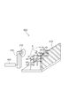
本発明の振動受粉装置100は、図1に模式的に示すように、植物Pに直接接触せず空気振動を発生させる加振手段110と該加振手段110を駆動する駆動手段120からなり、植物Pの花Fに空気振動によって間接的に振動を与えるように構成されている。
本発明の振動受粉装置100は、図1に模式的に示すように、植物Pに直接接触せず空気振動を発生させる加振手段110と該加振手段110を駆動する駆動手段120からなり、植物Pの花Fに空気振動によって間接的に振動を与えるように構成されている。
加振手段110は、空気振動を発生させる振動板111と、該振動板111に振動を与える電磁アクチュエータ112からなり、駆動手段120は駆動信号発生手段121を備え、電磁アクチュエータ112が駆動信号発生手段121からの電気信号をによって駆動されることにより振動板111が振動して空気振動が発生する。
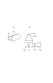
なお、加振手段110は、図2(a)に示すように、植物Pを挟んで対向する位置に反射板113設け、より効率的に空気振動を植物Pに与えるようにしても良い。
また、図2(b)に示すように、2つの振動板111a、111bおよび電磁アクチュエータ112a、112bを反対方向に向けて同時に駆動して、両方向の植物に同時に振動を与えるようにしても良い。
さらに、図2(c)に示すように、2つの振動板111a、111bおよび電磁アクチュエータ112a、112bを同一の植物Pに指向させ指向方向の交点での加振力が増大するようにしても良い。
また、図2(b)に示すように、2つの振動板111a、111bおよび電磁アクチュエータ112a、112bを反対方向に向けて同時に駆動して、両方向の植物に同時に振動を与えるようにしても良い。
さらに、図2(c)に示すように、2つの振動板111a、111bおよび電磁アクチュエータ112a、112bを同一の植物Pに指向させ指向方向の交点での加振力が増大するようにしても良い。
本発明の第1実施例である振動受粉装置200は、図3に示すように、複数の植物P対して直接接触せず空気振動を発生させる加振手段210が固定台230に固定されて設けられ、植物Pを挟んで対向する位置に反射板213が設けられており、人工授粉時に駆動手段220によって加振手段210が駆動されて空気振動を発生させ、植物Pの花に空気振動によって間接的に振動を与えるように構成されている。
加振手段210から発生する空気振動は、植物Pの花が効果的に振動する振幅、振動数に設定され、当該振動により花粉を散らし、花の雌ずいの柱頭に付着させることで確実に受精させて着果させることができる。
このことにより、固定台230に加振手段210を設置する作業のみで人工授粉を行うことができ、作業が単純化され、植物に傷をつけることなく、作業効率を向上させる事ができる。
また、植物Pを挟んで対向する位置に反射板213が設けられていることにより、植物Pを振動させる加振力が向上するとともに、空気振動による周囲への騒音の漏洩が低減する。
このことにより、固定台230に加振手段210を設置する作業のみで人工授粉を行うことができ、作業が単純化され、植物に傷をつけることなく、作業効率を向上させる事ができる。
また、植物Pを挟んで対向する位置に反射板213が設けられていることにより、植物Pを振動させる加振力が向上するとともに、空気振動による周囲への騒音の漏洩が低減する。
本発明の第2実施例である振動受粉装置300は、図4に示すように、複数の植物P対して直接接触せず空気振動を発生させる加振手段310が走行台車331に固定されて設けられ、該走行台車331は、複数の植物Pの列の側方に沿って設けられた走行レール332上を移動可能に構成されている。
人工授粉時には走行台車331が走行レール332を移動しながら、加振手段310が駆動されて空気振動を発生させ、植物Pの花に空気振動によって間接的に振動を与えるように構成されている。
加振手段310から発生する空気振動の振幅、振動数および走行台車331の移動速度は、植物Pの花が効果的に振動するように設定されることで、当該振動により花粉を散らし、花の雌ずいの柱頭に付着させることで確実に受精させて着果させることができる。
このことにより、植物Pを栽培する栽培地が広くても、走行レール332を設置することで、すべての植物に対して走行台車331を走行させて人工授粉を行うことができ、作業が単純化され、植物に傷をつけることなく、作業効率を向上させる事ができる。
加振手段310から発生する空気振動の振幅、振動数および走行台車331の移動速度は、植物Pの花が効果的に振動するように設定されることで、当該振動により花粉を散らし、花の雌ずいの柱頭に付着させることで確実に受精させて着果させることができる。
このことにより、植物Pを栽培する栽培地が広くても、走行レール332を設置することで、すべての植物に対して走行台車331を走行させて人工授粉を行うことができ、作業が単純化され、植物に傷をつけることなく、作業効率を向上させる事ができる。
また、加振手段310が植物Pの直近を通過可能なため、植物Pの花により効果的に空気振動が伝わり、さらに確実に受精させて着果させることができる。
なお、本実施例では加振手段310を走行方向に複数個並べており、このことで、広い範囲に存在する植物を同時に加振することができるため、走行台車331の走行速度を向上させることができ、さらに作業効率が向上する。
また、複数の加振手段310を、前述した配置例のように、指向方向の交点での加振力が増大するよう配置にしても良い。
なお、本実施例では加振手段310を走行方向に複数個並べており、このことで、広い範囲に存在する植物を同時に加振することができるため、走行台車331の走行速度を向上させることができ、さらに作業効率が向上する。
また、複数の加振手段310を、前述した配置例のように、指向方向の交点での加振力が増大するよう配置にしても良い。
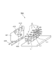
本発明の第3実施例である振動受粉装置400は、図5に示すように、複数の植物P対して直接接触せず空気振動を発生させる加振手段410が走行台車431に固定されて設けられ、該走行台車431は、複数の植物Pの列の側方に沿って設けられた走行レール432上を移動可能に構成されている。
また、走行台車431には撮像手段、温度センサ、湿度センサ等の環境センサ422が設けられており、走行台車431の位置近辺の環境情報を検出するように構成されている。
また、走行台車431には撮像手段、温度センサ、湿度センサ等の環境センサ422が設けられており、走行台車431の位置近辺の環境情報を検出するように構成されている。
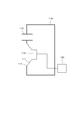
駆動手段420は、図6に示すように、制御手段423が環境センサ422の検出した環境情報を受けて駆動信号発生手段421を制御することにより、加振手段410から発生する空気振動の振幅、振動数を最適とするものである。
また、図示していないが、制御手段423が走行台車431の移動・停止や走行速度を制御しても良い。
また、図示していないが、制御手段423が走行台車431の移動・停止や走行速度を制御しても良い。
人工授粉時には走行台車431が走行レール432を移動しながら、環境センサ422によって検知された環境情報に応じて走行台車431の走行や加振手段410が制御されて、植物Pの花に空気振動によって間接的に振動を与えるように構成されている。
例えば、環境センサ422が撮像手段の場合、複数の植物Pの間隔が、図5に示すように、L1、L2、L3と不等間隔であっても、加振手段410から発生する空気振動の振幅や走行台車431の移動速度を可変とすることで、植物Pの花が効果的に振動するように制御でき、当該振動により花粉を散らし、花の雌ずいの柱頭に付着させることで確実に受精させて着果させることができる。
また、植物Pの花の位置を検出して、加振手段410の指向する方向を制御しても良い。
また、植物Pの花の位置を検出して、加振手段410の指向する方向を制御しても良い。
環境センサ422が温度センサや湿度センサの場合、温度や湿度に応じて花粉が有効に飛散する振動数や振幅が変化するため、加振手段410から発生する空気振動の振幅、振動数を制御することでその検出結果によりこのことにより、当該振動により花粉を散らし、花の雌ずいの柱頭に付着させることで確実に受精させて着果させることができる。
なお、加振手段はより指向性を向上させるため、図7に示すように、振動板111の前方にホーン状の指向板114を設けても良い。
また、加振手段が空気振動を与える効率を向上させるため、図8に示すように、ダクト116および開口部117を除いて密封された共鳴箱115に、振動板111と電磁アクチュエータ112を振動板111が開口部117を塞ぐように収容しても良い。
また、加振手段が空気振動を与える効率を向上させるため、図8に示すように、ダクト116および開口部117を除いて密封された共鳴箱115に、振動板111と電磁アクチュエータ112を振動板111が開口部117を塞ぐように収容しても良い。
以上述べたように、本発明によれば、植物の一株一株に対して直接接触させるための作業がなくなるため、作業量が大幅に減少して効率を向上することができるとともに、直接植物に接触することがなく、植物の株全体ではなく花位置付近のみを振動させることができるため、植物に傷をつけることはなく、加振作業を効率良く素早く行うことができ、作業速度を上げて効率を向上することができるなど、その効果は甚大である。
なお、上記実施例では、固定台230や走行レール332、432を地面(床面)に設けているが、これらを上方に設けても良い。
また、送風装置等を併用して、花粉を循環させて受粉をより確実にしても良く、植物の大きさが小さい場合には、植物と加振手段をともにカバー等で覆って、空気振動の漏洩をさらに少なすることで、植物を振動させる加振力を向上し周囲への騒音の漏洩を低減しても良い。
また、送風装置等を併用して、花粉を循環させて受粉をより確実にしても良く、植物の大きさが小さい場合には、植物と加振手段をともにカバー等で覆って、空気振動の漏洩をさらに少なすることで、植物を振動させる加振力を向上し周囲への騒音の漏洩を低減しても良い。
100、200、300、400 ・・・振動受粉装置
110、210、310、410 ・・・加振手段
111、 411 ・・・振動板
112、 412 ・・・電磁アクチュエータ
113、213 ・・・反射板
114 ・・・指向板
115 ・・・共鳴箱
116 ・・・ダクト
117 ・・・開口部
120、220、 420 ・・・駆動手段
121、 421 ・・・駆動信号発生手段
422 ・・・環境センサ
423 ・・・制御手段
230 ・・・固定台
331、431 ・・・走行台車
332、432 ・・・走行レール
P ・・・植物
F ・・・花
110、210、310、410 ・・・加振手段
111、 411 ・・・振動板
112、 412 ・・・電磁アクチュエータ
113、213 ・・・反射板
114 ・・・指向板
115 ・・・共鳴箱
116 ・・・ダクト
117 ・・・開口部
120、220、 420 ・・・駆動手段
121、 421 ・・・駆動信号発生手段
422 ・・・環境センサ
423 ・・・制御手段
230 ・・・固定台
331、431 ・・・走行台車
332、432 ・・・走行レール
P ・・・植物
F ・・・花
Claims (9)
- 植物に振動を与える加振手段と、該加振手段を駆動する駆動手段とを有する振動受粉装置において、
前記加振手段が、植物に直接接触せず空気振動を発生させる振動板と、該振動板に振動を与える電磁アクチュエータとを備え、
前記駆動手段が、前記電磁アクチュエータを電気信号により駆動する駆動信号発生手段を備えていることを特徴とする振動受粉装置。 - 前記加振手段が、移動可能な台車に設けられていることを特徴とする請求項1に記載の振動受粉装置。
- 前記加振手段が、前記振動板の空気振動を発生させる方向を可変とする方向変更手段を有していることを特徴とする請求項1または請求項2に記載の振動受粉装置。
- 前記駆動手段が、環境センサと、該環境センサの信号を処理して前記駆動信号発生手段、方向変更手段および台車の移動の少なくとも一つを制御する制御手段を有していることを特徴とする請求項1乃至請求項3のいずれかに記載の振動受粉装置。
- 前記環境センサが、加振手段とともに移動可能な台車に設けられていることを特徴とする請求項4に記載の振動受粉装置。
- 前記環境センサが、撮像手段を含み、
前記制御手段が、前記撮像手段によって植物の花の位置を判定して前記方向変更手段および台車の移動の少なくとも一つを制御することを特徴とする請求項4または請求項5に記載の振動受粉装置。 - 前記環境センサが、温度センサおよび湿度センサを含み、
前記制御手段が、前記温度センサおよび湿度センサによって植物の受粉に最適な振幅および振動数を判定して駆動信号発生手段を制御することを特徴とする請求項4乃至請求項6のいずれかに記載の振動受粉装置。 - 前記加振手段が、複数設けられていることを特徴とする請求項1乃至請求項7のいずれかに記載の振動受粉装置。
- 前記加振手段が、振動板の振動を増幅あるいは指向性を高める反射手段あるいは共鳴手段を有することを特徴とする請求項1乃至請求項8のいずれかに記載の振動受粉装置。
Applications Claiming Priority (2)
| Application Number | Priority Date | Filing Date | Title |
|---|---|---|---|
| JP2010-010288 | 2010-01-20 | ||
| JP2010010288A JP2011147377A (ja) | 2010-01-20 | 2010-01-20 | 振動受粉装置 |
Publications (1)
| Publication Number | Publication Date |
|---|---|
| WO2011090041A1 true WO2011090041A1 (ja) | 2011-07-28 |
Family
ID=44306843
Family Applications (1)
| Application Number | Title | Priority Date | Filing Date |
|---|---|---|---|
| PCT/JP2011/050807 Ceased WO2011090041A1 (ja) | 2010-01-20 | 2011-01-19 | 振動受粉装置 |
Country Status (2)
| Country | Link |
|---|---|
| JP (1) | JP2011147377A (ja) |
| WO (1) | WO2011090041A1 (ja) |
Cited By (9)
| Publication number | Priority date | Publication date | Assignee | Title |
|---|---|---|---|---|
| CN102599045A (zh) * | 2012-03-16 | 2012-07-25 | 江苏省农业科学院 | 便携式花粉药液授粉喷雾器 |
| WO2013099502A1 (ja) * | 2011-12-28 | 2013-07-04 | 株式会社椿本チエイン | 受粉装置 |
| WO2013121635A1 (ja) * | 2012-02-15 | 2013-08-22 | 株式会社椿本チエイン | 受粉装置及び植物の受粉方法 |
| JP2015043741A (ja) * | 2013-08-29 | 2015-03-12 | 国立大学法人京都大学 | 人工授粉装置及び人工授粉方法 |
| CN104585024A (zh) * | 2015-01-29 | 2015-05-06 | 农业部南京农业机械化研究所 | 一种果树授粉装置 |
| JP2020115855A (ja) * | 2019-01-25 | 2020-08-06 | 国立研究開発法人農業・食品産業技術総合研究機構 | 集束超音波を利用したコナジラミ類害虫、アブラムシ類害虫又はカメムシ類害虫を防除する方法 |
| CN112088772A (zh) * | 2020-10-15 | 2020-12-18 | 沈阳农业大学 | 一种温室番茄震荡授粉装置和方法 |
| PL238350B1 (pl) * | 2018-04-25 | 2021-08-09 | B Droix Spolka Z Ograniczona Odpowiedzialnoscia | Mobilne urządzenie do zapylania roślin z wymuszeniem oscylacyjnym |
| US11470784B2 (en) | 2017-03-21 | 2022-10-18 | Paul Richard GAUVREAU, Jr. | Unmanned aerial vehicle for augmenting plant pollination |
Families Citing this family (5)
| Publication number | Priority date | Publication date | Assignee | Title |
|---|---|---|---|---|
| KR102784395B1 (ko) * | 2017-05-04 | 2025-03-19 | 아루까 에이. 아이 파밍 엘티디 | 식물 처리 시스템 및 방법 |
| JP6870536B2 (ja) * | 2017-08-29 | 2021-05-12 | 井関農機株式会社 | 植物栽培設備における人工受粉用車両 |
| JP6933152B2 (ja) * | 2018-01-30 | 2021-09-08 | 井関農機株式会社 | 栽培ベッド用の作業車両 |
| US12207605B2 (en) | 2018-11-07 | 2025-01-28 | Arugga A.I Farming Ltd | Automated plant treatment systems and methods |
| KR102128266B1 (ko) * | 2020-02-19 | 2020-06-30 | 주식회사 판다코퍼레이션 | IoT 기술을 이용하여 농산물을 생산하는 방법 및 이를 위한 장치 |
Citations (3)
| Publication number | Priority date | Publication date | Assignee | Title |
|---|---|---|---|---|
| JPH0646675A (ja) * | 1992-06-26 | 1994-02-22 | Toshiba Eng & Constr Co Ltd | 花卉苗の生産方法 |
| JP2003271153A (ja) * | 2002-03-14 | 2003-09-25 | Yokogawa Electric Corp | 音声伝達装置 |
| JP2004033125A (ja) * | 2002-07-04 | 2004-02-05 | Daito Tec Kk | 温室の制御装置 |
-
2010
- 2010-01-20 JP JP2010010288A patent/JP2011147377A/ja active Pending
-
2011
- 2011-01-19 WO PCT/JP2011/050807 patent/WO2011090041A1/ja not_active Ceased
Patent Citations (3)
| Publication number | Priority date | Publication date | Assignee | Title |
|---|---|---|---|---|
| JPH0646675A (ja) * | 1992-06-26 | 1994-02-22 | Toshiba Eng & Constr Co Ltd | 花卉苗の生産方法 |
| JP2003271153A (ja) * | 2002-03-14 | 2003-09-25 | Yokogawa Electric Corp | 音声伝達装置 |
| JP2004033125A (ja) * | 2002-07-04 | 2004-02-05 | Daito Tec Kk | 温室の制御装置 |
Non-Patent Citations (5)
| Title |
|---|
| KOSUKE NAGAYA: "Control of mechanical vibration and noise by the electromagnetic force", SCIENCE OF MACHINE, vol. 52, no. 5, 2000, pages 538 - 546 * |
| MASAHIRO MOROKUMA ET AL.: "Effects of High Temperature and High Humidity during the Flowering Period on Spikelet Fertility in Japonica Rice", JAPANESE JOURNAL OF CROP SCIENCE, vol. 73, no. 1, 2004, pages 93 - 98 * |
| NAHIR, D. ET AL.: "Pollination of tomato flowers by a pulsating air jet", TRANSACTIONS ASAE, vol. 27, no. 3, 1984, pages 894 - 896 * |
| SHIN'ICHI ADANIYA ET AL.: "Effects of temperature and relative humidity on pollen germinabiblity and pollen tube growth in the style of Zingiber mioga Roscoe", JOURNAL OF THE JAPANESE SOCIETY FOR HORTICULTURAL SCIENCE, vol. 57, no. 1, 1988, pages 43 - 51 * |
| WANG, Z.M.: "Is climate simulation in growth chambers necessary?", BIOTRONICS, vol. 28, 1999, pages 13 - 21 * |
Cited By (10)
| Publication number | Priority date | Publication date | Assignee | Title |
|---|---|---|---|---|
| WO2013099502A1 (ja) * | 2011-12-28 | 2013-07-04 | 株式会社椿本チエイン | 受粉装置 |
| WO2013121635A1 (ja) * | 2012-02-15 | 2013-08-22 | 株式会社椿本チエイン | 受粉装置及び植物の受粉方法 |
| CN102599045A (zh) * | 2012-03-16 | 2012-07-25 | 江苏省农业科学院 | 便携式花粉药液授粉喷雾器 |
| JP2015043741A (ja) * | 2013-08-29 | 2015-03-12 | 国立大学法人京都大学 | 人工授粉装置及び人工授粉方法 |
| CN104585024A (zh) * | 2015-01-29 | 2015-05-06 | 农业部南京农业机械化研究所 | 一种果树授粉装置 |
| US11470784B2 (en) | 2017-03-21 | 2022-10-18 | Paul Richard GAUVREAU, Jr. | Unmanned aerial vehicle for augmenting plant pollination |
| PL238350B1 (pl) * | 2018-04-25 | 2021-08-09 | B Droix Spolka Z Ograniczona Odpowiedzialnoscia | Mobilne urządzenie do zapylania roślin z wymuszeniem oscylacyjnym |
| JP2020115855A (ja) * | 2019-01-25 | 2020-08-06 | 国立研究開発法人農業・食品産業技術総合研究機構 | 集束超音波を利用したコナジラミ類害虫、アブラムシ類害虫又はカメムシ類害虫を防除する方法 |
| JP7352258B2 (ja) | 2019-01-25 | 2023-09-28 | 国立研究開発法人農業・食品産業技術総合研究機構 | 集束超音波を利用したコナジラミ類害虫、アブラムシ類害虫又はカメムシ類害虫を防除する方法 |
| CN112088772A (zh) * | 2020-10-15 | 2020-12-18 | 沈阳农业大学 | 一种温室番茄震荡授粉装置和方法 |
Also Published As
| Publication number | Publication date |
|---|---|
| JP2011147377A (ja) | 2011-08-04 |
Similar Documents
| Publication | Publication Date | Title |
|---|---|---|
| WO2011090041A1 (ja) | 振動受粉装置 | |
| US7706547B2 (en) | System and method for noise cancellation | |
| JP5423370B2 (ja) | 音源探査装置 | |
| EP1544635A4 (en) | SOUND SOURCE SEARCH SYSTEM | |
| DE60039374D1 (de) | Anordnung eines akustischen Arrays mit einem Schallgeschwindigkeitsmesser | |
| EP4349162A3 (en) | Plant cultivation apparatus | |
| CN103797379A (zh) | 用于多方向测量的超声测量组件 | |
| JP2016037808A (ja) | メンテナンスシステム | |
| JP2012085586A (ja) | 振動受粉装置 | |
| US20190025159A1 (en) | Vibration and noise mapping system and method | |
| CN103817064A (zh) | 二维压电振动平台 | |
| KR20130069462A (ko) | 스피커 시스템 | |
| JP2018001370A (ja) | 振動低減制御装置、及びロボット | |
| CN106054131A (zh) | 声源定位系统和方法 | |
| Anderson et al. | Optimized driver placement for array-driven flat-panel loudspeakers | |
| Puri et al. | Global active control of harmonic noise in a vibro-acoustic cavity using Modal FxLMS algorithm | |
| JP2009198839A5 (ja) | ||
| Ju et al. | Near-field characteristics of the parametric loudspeaker using ultrasonic transducers | |
| US6871572B1 (en) | Drive for precision oscillations | |
| JP2016047125A5 (ja) | 被検体情報取得装置および信号処理方法 | |
| JP6171217B2 (ja) | 人工授粉装置及び人工授粉方法 | |
| KR101294292B1 (ko) | 초음파 변조를 통한 음파 집속 및 방향성 부여 장치 및 방법 | |
| Janssens et al. | On-line sound brush measurement technique for 3D noise emission studies | |
| JP2014045680A (ja) | 受粉装置 | |
| EP3135953A1 (en) | Active vibration damping device and design method |
Legal Events
| Date | Code | Title | Description |
|---|---|---|---|
| 121 | Ep: the epo has been informed by wipo that ep was designated in this application |
Ref document number: 11734647 Country of ref document: EP Kind code of ref document: A1 |
|
| NENP | Non-entry into the national phase |
Ref country code: DE |
|
| 122 | Ep: pct application non-entry in european phase |
Ref document number: 11734647 Country of ref document: EP Kind code of ref document: A1 |