WO2011086781A1 - シャッタ構造および自動取引装置 - Google Patents
シャッタ構造および自動取引装置 Download PDFInfo
- Publication number
- WO2011086781A1 WO2011086781A1 PCT/JP2010/071497 JP2010071497W WO2011086781A1 WO 2011086781 A1 WO2011086781 A1 WO 2011086781A1 JP 2010071497 W JP2010071497 W JP 2010071497W WO 2011086781 A1 WO2011086781 A1 WO 2011086781A1
- Authority
- WO
- WIPO (PCT)
- Prior art keywords
- shutter
- automatic transaction
- transaction apparatus
- drainage
- exemplary embodiment
- Prior art date
- Legal status (The legal status is an assumption and is not a legal conclusion. Google has not performed a legal analysis and makes no representation as to the accuracy of the status listed.)
- Ceased
Links
Images
Classifications
-
- G—PHYSICS
- G07—CHECKING-DEVICES
- G07F—COIN-FREED OR LIKE APPARATUS
- G07F19/00—Complete banking systems; Coded card-freed arrangements adapted for dispensing or receiving monies or the like and posting such transactions to existing accounts, e.g. automatic teller machines
- G07F19/20—Automatic teller machines [ATMs]
- G07F19/205—Housing aspects of ATMs
Definitions
- the present invention relates to a shutter structure in an automatic transaction apparatus such as an automatic teller machine that performs a desired transaction by inserting a medium such as cash.
- a storage unit that stores banknotes to be deposited and withdrawn generally has a structure in which banknotes are stored in a standing position.
- the shutter of the deposit / withdrawal port has a structure that is inclined horizontally or forward.
- a liquid such as a drink may be applied to the shutter, or the shutter may be exposed to rainwater or the like (hereinafter referred to as “water etc.”) in an automatic transaction apparatus installed on the outer wall.
- water or the like enters the automatic transaction apparatus from the gap between the shutter and the apparatus housing, causing a malfunction of the apparatus.
- the shutter 302 is provided with an appropriate inclination, and walls 302b and 302c are provided on the left and right ends thereof.
- water or the like is guided to the drainage channel 315, and the drainage channel 315 is inclined toward the drainage port 317 to increase drainage efficiency.
- the bottom end of the shutter has an inclination to the left and right to allow drainage even in the case of a very small amount of rain, but a projection 340 is provided to allow drainage along the projection 340.
- a projection 340 is provided to allow drainage along the projection 340.
- the water that remains when the shutter 302 is opened follows the left and right drainage channels 316a and 316b by following the inclination of the protrusion 340 to the left and right. It was set as the structure drained (for example, refer patent 3959297 gazette).
- the lower end of the inclined shutter 302 is recessed below the housing surface 313. For this reason, in the prior art, when a large amount of water or the like enters the shutter surface, such as spilling a drink, the drainage destination of water or the like is only the drainage channel, the drainage capacity cannot catch up, and the drainage channel overflows.
- the lower end of the shutter is shaped so as to enter below the housing surface, water or the like tends to remain on the surface of the overlapping shutter. Therefore, when there is no transaction and there is no operation for opening the shutter for a long time, water or the like continues to remain, and the lower end of the shutter becomes unclean.
- a first aspect of the present invention is an automatic transaction apparatus, which is a slope-shaped shutter having side wall surfaces on both side surfaces, a side wall surface of the shutter, and a position lower than the shutter surface when the shutter is closed.
- a housing cover that covers the lower end of the shutter, and a gutter that has a drain and is arranged to cover the lower end of the shutter from below when the shutter is closed.
- the automatic transaction apparatus of the first aspect of the present invention it is possible to obtain a sufficient amount of drainage without increasing the drainage structure, preventing drainage from catching up, and preventing water and the like from accumulating on the shutter surface. it can.
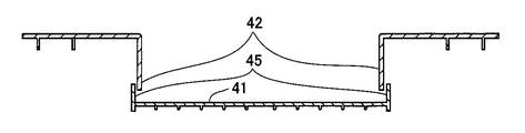
- FIG. 5 is a cross-sectional view taken along line XX of FIG. 4 of the automatic transaction apparatus according to the first exemplary embodiment.
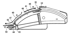
- FIG. 6 is a cross-sectional view of the automatic transaction apparatus according to the first exemplary embodiment taken along the line YY of FIG. 4.
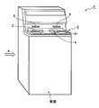
- the automatic transaction apparatus has an appearance as shown in FIG. 1, and includes a coin deposit / withdrawal port 2, a banknote deposit / withdrawal port 3, an operation unit 4, a passbook insertion port 5, and a card insertion port 6. I have.
- the coin deposit / withdrawal port 2 and the bill deposit / withdrawal port 3 are openings through which coins and bills are inserted and discharged, respectively.
- Each of the coin deposit / withdrawal port 2 and the banknote deposit / withdrawal port 3 is provided with a shutter 41. When the shutter 41 is driven, the coin deposit / withdrawal port 2 and the banknote deposit / withdrawal port 3 are each opened and closed.
- a coin processing unit 25 and a banknote processing unit 26 are provided for performing deposit and withdrawal processing of coins and banknotes described later.
- the passbook used in the transaction is inserted from here, and when the transaction is completed, the passbook is discharged.
- a passbook processing unit 23 to be described later is provided at the back of the passbook insertion slot 5.
- the card insertion slot 6 is a part into which a card is inserted or ejected.
- a card processing unit 21 to be described later is provided at the back of the card insertion slot 6.
- the operation unit 4 is configured integrally with an LCD for displaying an operation screen during a transaction and a touch panel for inputting a transaction selection, a password, a transaction amount, and the like.
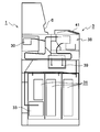
- FIG. 2 is a side view showing the internal configuration of the automatic transaction apparatus according to the first exemplary embodiment, as viewed from the direction of arrow A in FIG.
- the coin processing unit 25 is omitted for simplification.
- a customer service unit 38, a discrimination unit 39, a temporary storage unit 30, and a bill storage unit 31 on the lower side of the automatic transaction apparatus according to the first exemplary embodiment are provided.
- a denomination-type cassette is provided.
- the customer service unit 38 includes an operation unit 4 operated by a user, a banknote deposit / withdrawal port 3 and the like.
- the discrimination unit 39 determines the authenticity of the banknote.
- the temporary holding unit 30 temporarily holds the deposited banknote.
- a reject banknote storage unit 33 for storing reject banknotes at the time of a scrutiny transaction or reject banknotes not received by the user.
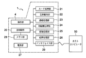
- the main control unit 20 and the operation unit 4 are provided in the control system of the automatic transaction apparatus according to the first exemplary embodiment.
- the main control unit 20 controls each unit described later.
- the operation unit 4 is operated by the user according to the displayed guidance.
- a shutter opening / closing operation described later is performed based on the control of the main control unit 20.
- control system of the automatic transaction apparatus includes a card processing unit 21, a voice guidance unit 22, a passbook processing unit 23, a statement slip processing unit 24, a coin processing unit 25, and a banknote processing unit 26.
- the card processing unit 21 reads / writes information such as an account number recorded on a cash card or the like.
- the voice guidance unit 22 outputs operation guidance and the like by voice.
- the passbook processing unit 23 performs read / write of the magnetic stripe of the passbook in which information such as an account number is recorded and print control to the passbook.
- the statement slip processing unit 24 prints out the transaction details.
- the coin processing unit 25 performs deposit / withdrawal control of coins.
- the banknote processing unit 26 performs banknote deposit and withdrawal control.
- the automatic transaction apparatus is provided with a power supply unit 27, a memory unit 28, and an interface unit 29.
- the power supply unit 27 supplies power to each unit.
- the memory unit 28 is a storage unit of the main control unit 20 and stores various control parameters.
- the interface unit 29 controls the interface with the host computer 50.
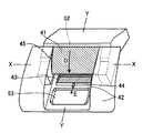
- FIGS. 4 is a schematic perspective view of the periphery of the shutter
- FIG. 5 is an XX sectional view of FIG. 4
- FIG. 6 is a YY sectional view of FIG.
- the shutter 41 of the automatic transaction apparatus 1 of the first exemplary embodiment has a slope shape as shown in FIG. Further, as shown in FIG. 5, the shutter 41 of the automatic transaction apparatus 1 of the first exemplary embodiment is provided with side wall surfaces 45 on both side surfaces of the shutter 41, and the side wall surfaces 45 are formed on the housing cover 42. It has a covered structure.
- the shutter lower end portion 47 is configured to be covered by the housing cover 42 when the shutter 41 is closed. Therefore, the housing cover 42 that covers the shutter lower end 47 is positioned lower than the shutter surface 48.
- the eaves 43 has a drainage port 44, and a water reservoir 53 for collecting water from the drainage port 44 is provided at the end.
- the water reservoir 53 does not need to be provided.
- the shutter upper end 51 has an upper end wall surface 52 and is covered with the housing cover 42.
- the shutter 41 of the automatic transaction apparatus operates as follows.
- the shutter 41 of the banknote deposit / withdrawal port 3 is opened based on the control of the main control unit 20 to prompt the insertion of banknotes. .
- the shutter lower end portion 47 moves upward as indicated by an arrow H in the shutter operation 46 shown in FIG.
- the automatic transaction apparatus prevents rainwater or water such as drinks from flowing into the apparatus.
- a side wall surface 45 is provided on the side surface of the shutter 1. Accordingly, when water or the like is applied to the shutter surface 48 with the shutter 41 closed, the water or the like flows downward along the sloped shutter surface 48.
- the shutter lower end portion 47 is covered with a housing cover 42 having a surface lower than the shutter surface 48. Therefore, most of the water and the like is drained through the main water channel 9 from the shutter surface 48 to the housing cover surface as shown by the arrow D in FIG.
- the remaining water or the like flows into the eaves 43 covering the bottom surface of the lower end 47 of the shutter, and is drained through the auxiliary water channel 50 directed to the drainage port 44 provided in the eaves 43.
- the shutter structure of the automatic transaction apparatus 1 according to the first exemplary embodiment operates. Therefore, the automatic transaction apparatus according to the first exemplary embodiment can obtain a sufficient amount of drainage without increasing the drainage structure, and the drainage does not catch up, and water or the like may accumulate on the shutter surface 48. Absent.
- the shutter upper end 51 also has an upper end wall surface 52 and is covered with the casing cover 42. Therefore, in the automatic transaction apparatus according to the first exemplary embodiment, water or the like does not flow into the apparatus from the shutter upper end 51 side even in the horizontal shutter 41 having a small slope inclination.
- the automatic transaction apparatus since it operates as described above, the automatic transaction apparatus according to the first exemplary embodiment has a large amount of drink even when a drink containing sweetener is spilled on the shutter 41 and the sweetener is deposited on the shutter 41. It is also possible to wash away the sweetener by pouring water over it.
- the automatic transaction apparatus includes a slope-shaped shutter having side wall surfaces on both side surfaces, a shutter when covering the side wall surface of the shutter and closing the shutter.
- a housing cover that covers the lower end of the shutter at a position lower than the surface, and a gutter that has a drainage port and that covers the lower end of the shutter from below when the shutter is closed. Therefore, the automatic transaction apparatus according to the first exemplary embodiment can obtain a sufficient amount of drainage without increasing the drainage structure, preventing the drainage from catching up and preventing water and the like from accumulating on the shutter surface. it can.
- the present invention can be widely used in an automatic transaction apparatus such as an automatic teller machine that opens and closes a shutter and inserts a medium such as a bill into a desired transaction.
Landscapes
- Business, Economics & Management (AREA)
- Accounting & Taxation (AREA)
- Finance (AREA)
- Physics & Mathematics (AREA)
- General Physics & Mathematics (AREA)
- Financial Or Insurance-Related Operations Such As Payment And Settlement (AREA)
- Devices For Checking Fares Or Tickets At Control Points (AREA)
- Control Of Vending Devices And Auxiliary Devices For Vending Devices (AREA)
Priority Applications (2)
| Application Number | Priority Date | Filing Date | Title |
|---|---|---|---|
| US13/504,940 US8701859B2 (en) | 2010-01-13 | 2010-12-01 | Shutter structure and automatic transaction apparatus |
| CN201080048225.4A CN102667876B (zh) | 2010-01-13 | 2010-12-01 | 闸门构造以及自动交易装置 |
Applications Claiming Priority (2)
| Application Number | Priority Date | Filing Date | Title |
|---|---|---|---|
| JP2010005301A JP5454155B2 (ja) | 2010-01-13 | 2010-01-13 | シャッタ構造および自動取引装置 |
| JP2010-005301 | 2010-01-13 |
Publications (1)
| Publication Number | Publication Date |
|---|---|
| WO2011086781A1 true WO2011086781A1 (ja) | 2011-07-21 |
Family
ID=44304072
Family Applications (1)
| Application Number | Title | Priority Date | Filing Date |
|---|---|---|---|
| PCT/JP2010/071497 Ceased WO2011086781A1 (ja) | 2010-01-13 | 2010-12-01 | シャッタ構造および自動取引装置 |
Country Status (4)
| Country | Link |
|---|---|
| US (1) | US8701859B2 (https=) |
| JP (1) | JP5454155B2 (https=) |
| CN (1) | CN102667876B (https=) |
| WO (1) | WO2011086781A1 (https=) |
Cited By (1)
| Publication number | Priority date | Publication date | Assignee | Title |
|---|---|---|---|---|
| CN108657563A (zh) * | 2018-03-22 | 2018-10-16 | 苏州朗威电子机械股份有限公司 | 一种智能云柜排水系统 |
Families Citing this family (6)
| Publication number | Priority date | Publication date | Assignee | Title |
|---|---|---|---|---|
| US10319171B2 (en) * | 2014-03-28 | 2019-06-11 | Ncr Corporation | Media escape prevention for self-service terminal |
| CN104112311A (zh) * | 2014-05-06 | 2014-10-22 | 昆山古鳌电子机械有限公司 | 一种纸币分离机构 |
| JP6303921B2 (ja) * | 2014-08-25 | 2018-04-04 | 沖電気工業株式会社 | 媒体取引装置 |
| CN104331977B (zh) * | 2014-10-30 | 2017-01-11 | 东莞职业技术学院 | 基于fpga的纸币多特征采集系统及方法 |
| CN106228708A (zh) * | 2016-07-15 | 2016-12-14 | 深圳怡化电脑股份有限公司 | 交互门装置以及纸币交互设备 |
| US10049532B1 (en) * | 2018-04-26 | 2018-08-14 | Capital One Services, Llc | Automated teller machine (ATM) device with sealed slot |
Citations (5)
| Publication number | Priority date | Publication date | Assignee | Title |
|---|---|---|---|---|
| JPS6353176U (https=) * | 1986-09-20 | 1988-04-09 | ||
| JPH06282724A (ja) * | 1993-03-30 | 1994-10-07 | Hitachi Ltd | 現金自動取引装置 |
| JP2003303366A (ja) * | 2002-04-10 | 2003-10-24 | Hitachi Ltd | 紙幣取扱装置 |
| JP2003346213A (ja) * | 2002-05-24 | 2003-12-05 | Hitachi Ltd | 紙幣取扱装置 |
| JP2009211575A (ja) * | 2008-03-06 | 2009-09-17 | Hitachi Omron Terminal Solutions Corp | 取引処理装置 |
Family Cites Families (1)
| Publication number | Priority date | Publication date | Assignee | Title |
|---|---|---|---|---|
| US4251009A (en) * | 1978-04-03 | 1981-02-17 | Mclaughlin Richard S | Security door assembly for an automatic document dispensing device |
-
2010
- 2010-01-13 JP JP2010005301A patent/JP5454155B2/ja active Active
- 2010-12-01 WO PCT/JP2010/071497 patent/WO2011086781A1/ja not_active Ceased
- 2010-12-01 CN CN201080048225.4A patent/CN102667876B/zh active Active
- 2010-12-01 US US13/504,940 patent/US8701859B2/en active Active
Patent Citations (5)
| Publication number | Priority date | Publication date | Assignee | Title |
|---|---|---|---|---|
| JPS6353176U (https=) * | 1986-09-20 | 1988-04-09 | ||
| JPH06282724A (ja) * | 1993-03-30 | 1994-10-07 | Hitachi Ltd | 現金自動取引装置 |
| JP2003303366A (ja) * | 2002-04-10 | 2003-10-24 | Hitachi Ltd | 紙幣取扱装置 |
| JP2003346213A (ja) * | 2002-05-24 | 2003-12-05 | Hitachi Ltd | 紙幣取扱装置 |
| JP2009211575A (ja) * | 2008-03-06 | 2009-09-17 | Hitachi Omron Terminal Solutions Corp | 取引処理装置 |
Cited By (1)
| Publication number | Priority date | Publication date | Assignee | Title |
|---|---|---|---|---|
| CN108657563A (zh) * | 2018-03-22 | 2018-10-16 | 苏州朗威电子机械股份有限公司 | 一种智能云柜排水系统 |
Also Published As
| Publication number | Publication date |
|---|---|
| JP5454155B2 (ja) | 2014-03-26 |
| US8701859B2 (en) | 2014-04-22 |
| US20120210916A1 (en) | 2012-08-23 |
| JP2011145840A (ja) | 2011-07-28 |
| CN102667876A (zh) | 2012-09-12 |
| CN102667876B (zh) | 2015-04-01 |
Similar Documents
| Publication | Publication Date | Title |
|---|---|---|
| JP5454155B2 (ja) | シャッタ構造および自動取引装置 | |
| CN103247104B (zh) | 纸币收纳装置 | |
| JP3959297B2 (ja) | 紙幣取扱装置 | |
| WO2016013324A1 (ja) | 媒体処理装置及び媒体取引装置 | |
| JP5039613B2 (ja) | 取引処理装置 | |
| US10395224B2 (en) | Financial device having a replaceable module for performing replenishment or collection function | |
| JP5267558B2 (ja) | 紙幣識別装置 | |
| JP2013167936A (ja) | 貨幣処理方法、貨幣処理装置、及び、貨幣処理システム | |
| JP5928143B2 (ja) | 媒体入出部及び媒体取引装置 | |
| JP4910494B2 (ja) | 自動取引装置 | |
| JP2021086301A (ja) | 媒体処理装置及び自動取引装置 | |
| JP5857720B2 (ja) | センサ及び監視装置 | |
| KR101709852B1 (ko) | 금융 기기 | |
| JP2004178455A (ja) | 自動取引装置 | |
| JP4899630B2 (ja) | カード払出装置 | |
| KR20060124938A (ko) | 금융자동화기기의 카세트 프레임 개폐구조 | |
| JP5277868B2 (ja) | 自動取引装置 | |
| KR20250009098A (ko) | 금융 자동화 기기 | |
| JP2025128930A (ja) | 媒体処理装置 | |
| JP6554902B2 (ja) | 媒体情報読取装置及び媒体取引装置 | |
| KR20240106607A (ko) | 매체 집적함 및 이를 포함하는 금융자동화기기 | |
| JP2007140705A (ja) | 金銭取扱い装置 | |
| JP3185375B2 (ja) | 硬貨処理装置 | |
| KR20160049633A (ko) | 금융자동화기기 및 이를 이용한 지폐 관리 방법 | |
| JP2021149477A (ja) | 媒体取扱装置 |
Legal Events
| Date | Code | Title | Description |
|---|---|---|---|
| WWE | Wipo information: entry into national phase |
Ref document number: 201080048225.4 Country of ref document: CN |
|
| 121 | Ep: the epo has been informed by wipo that ep was designated in this application |
Ref document number: 10843136 Country of ref document: EP Kind code of ref document: A1 |
|
| WWE | Wipo information: entry into national phase |
Ref document number: 13504940 Country of ref document: US |
|
| NENP | Non-entry into the national phase |
Ref country code: DE |
|
| 122 | Ep: pct application non-entry in european phase |
Ref document number: 10843136 Country of ref document: EP Kind code of ref document: A1 |