WO2011077937A1 - 基板乾燥装置及び基板乾燥方法 - Google Patents
基板乾燥装置及び基板乾燥方法 Download PDFInfo
- Publication number
- WO2011077937A1 WO2011077937A1 PCT/JP2010/071855 JP2010071855W WO2011077937A1 WO 2011077937 A1 WO2011077937 A1 WO 2011077937A1 JP 2010071855 W JP2010071855 W JP 2010071855W WO 2011077937 A1 WO2011077937 A1 WO 2011077937A1
- Authority
- WO
- WIPO (PCT)
- Prior art keywords
- substrate
- magnet
- drying
- wafer
- liquid
- Prior art date
- Legal status (The legal status is an assumption and is not a legal conclusion. Google has not performed a legal analysis and makes no representation as to the accuracy of the status listed.)
- Ceased
Links
Images






Classifications
-
- H—ELECTRICITY
- H10—SEMICONDUCTOR DEVICES; ELECTRIC SOLID-STATE DEVICES NOT OTHERWISE PROVIDED FOR
- H10P—GENERIC PROCESSES OR APPARATUS FOR THE MANUFACTURE OR TREATMENT OF DEVICES COVERED BY CLASS H10
- H10P72/00—Handling or holding of wafers, substrates or devices during manufacture or treatment thereof
- H10P72/04—Apparatus for manufacture or treatment
- H10P72/0402—Apparatus for fluid treatment
- H10P72/0406—Apparatus for fluid treatment for cleaning followed by drying, rinsing, stripping, blasting or the like
- H10P72/0408—Apparatus for fluid treatment for cleaning followed by drying, rinsing, stripping, blasting or the like for drying
-
- H—ELECTRICITY
- H10—SEMICONDUCTOR DEVICES; ELECTRIC SOLID-STATE DEVICES NOT OTHERWISE PROVIDED FOR
- H10P—GENERIC PROCESSES OR APPARATUS FOR THE MANUFACTURE OR TREATMENT OF DEVICES COVERED BY CLASS H10
- H10P50/00—Etching of wafers, substrates or parts of devices
-
- F—MECHANICAL ENGINEERING; LIGHTING; HEATING; WEAPONS; BLASTING
- F26—DRYING
- F26B—DRYING SOLID MATERIALS OR OBJECTS BY REMOVING LIQUID THEREFROM
- F26B5/00—Drying solid materials or objects by processes not involving the application of heat
-
- H—ELECTRICITY
- H10—SEMICONDUCTOR DEVICES; ELECTRIC SOLID-STATE DEVICES NOT OTHERWISE PROVIDED FOR
- H10P—GENERIC PROCESSES OR APPARATUS FOR THE MANUFACTURE OR TREATMENT OF DEVICES COVERED BY CLASS H10
- H10P70/00—Cleaning of wafers, substrates or parts of devices
- H10P70/10—Cleaning before device manufacture, i.e. Begin-Of-Line process
- H10P70/15—Cleaning before device manufacture, i.e. Begin-Of-Line process by wet cleaning only
Definitions
- the present invention relates to a substrate drying apparatus and a substrate drying method for drying a substrate washed with a diamagnetic liquid using a magnet.
- a substrate processing apparatus that holds a semiconductor wafer (hereinafter referred to as “wafer”) by a spin chuck, supplies a chemical solution, and cleans it.
- wafer a semiconductor wafer
- a cleaning process using such an apparatus after a chemical solution or pure water is supplied to a wafer, the wafer is rotated and dried by shaking off droplets by centrifugal force.
- a method of drying the wafer there are a method of spraying a vapor such as IPA (isopropyl alcohol) on the wafer while rotating the wafer, a method of spraying mist-like IPA, a method of supplying an IPA liquid and the like. Also, a method of drying the wafer (Marangoni) by spraying steam such as IPA on the center side from the pure water supply position while supplying pure water to the wafer from a nozzle moving from the center of the wafer toward the periphery. Drying) has been proposed (for example, Patent Document 1). When the IPA gas is sprayed on the wafer, the IPA gas locally dissolves on the water surface on the wafer, and density difference Marangoni convection is generated. For this reason, the flow of water at the gas-liquid interface is generated, and it is possible to prevent the minute droplets from separating from the water droplets and the minute droplets from being generated.
- IPA isopropyl alcohol
- the present invention has been made in view of such circumstances. By moving a magnet along the substrate such as a wafer to the edge side of the substrate, it is possible to cause droplets to remain on the substrate as compared with Marangoni drying.
- the present invention provides a substrate drying apparatus and a substrate drying method that can more effectively prevent and suppress the generation of watermarks.
- a substrate drying apparatus is a substrate drying apparatus for drying a substrate washed with a liquid having diamagnetism, a magnet for moving the liquid attached to the substrate by magnetic force, and the magnet along the substrate. And a magnet conveying means for moving to the edge side of the substrate.
- the substrate drying apparatus includes a spin chuck that holds and rotates a disk-shaped substrate, and the magnet conveying means moves the magnet along the substrate from a substantially central portion of the substrate to a radially outer side.
- a moving mechanism is provided.
- the magnet has a first magnet and a second magnet that are arranged to face each other such that the magnetic poles are counter electrodes, and the opposing direction of the first magnet and the second magnet is It is characterized by being non-parallel to the substrate held by the spin chuck.
- the substrate drying apparatus includes contact / separation means for causing the first magnet and the second magnet to approach and separate from each other.
- the substrate drying apparatus is characterized in that the contacting / separating means includes means for causing the first magnet and the second magnet to approach each other at a substantially central portion of the substrate.
- the substrate drying apparatus holds each magnet so that the first magnet faces one surface side of the substrate held by the spin chuck and the second magnet faces the other surface side of the substrate.
- pillar which supports this arm part are provided,
- the said contact / separation means is provided with the raising / lowering mechanism which raises / lowers the said arm part along the said support
- the substrate drying apparatus includes a drying gas supply nozzle for supplying a drying gas to the substrate, the first magnet has a hole opening in the facing direction, and the drying gas supply nozzle is the hole. It is characterized by being inserted in.
- the substrate drying method according to the present invention is a substrate drying method for drying a substrate washed with a liquid having diamagnetism, a magnet for moving the liquid attached to the substrate by a magnetic force is brought close to the substrate, and the magnet is The substrate is moved along the substrate toward the edge of the substrate.
- a substrate drying method is a substrate drying method for drying a substrate washed with a liquid having diamagnetism, and a magnet for rotating a disk-shaped substrate and moving the liquid attached to the substrate by magnetic force.
- the magnet is moved close to the substantially central portion of the substrate, and the magnet is moved radially outward from the substantially central portion of the substrate along the substrate.
- the liquid attached to the substrate moves to the edge side of the substrate. Accordingly, the liquid can be removed from the substrate, that is, dried. Since the magnetic force related to diamagnetism acting on the liquid attached to the substrate acts on the entire liquid, the microdroplet also moves to the edge side of the substrate by the magnetic force.
- the minute droplet may be left behind, but when the magnet moving to the edge side of the substrate approaches the left minute droplet, A larger magnetic force acts on the remaining micro droplets than on the large droplets that have moved to the edge side. For this reason, it is possible to move the micro droplets so as to push them back toward the large droplets, and to take them into the droplets. Therefore, compared with conventional Marangoni drying, it is possible to reduce the fine droplets remaining on the substrate.
- the liquid adhering to the substrate moves outward in the radial direction of the substrate by centrifugal force. Further, by moving the magnet from the substantially central portion of the substrate to the outside in the radial direction, the liquid attached to the substrate moves to the outside in the radial direction. Therefore, the liquid is more effectively removed from the substrate.
- the opposing directions of the first magnet and the second magnet arranged opposite to each other are non-parallel to the substrate. Therefore, the first and second magnets can be opposed to each other at the substantially central portion of the disk-shaped substrate while avoiding the rotation axis of the spin chuck, and the magnetic force of the magnet can be exerted on the central portion.
- the liquid adhering to the substrate portion sandwiched between the first magnet and the second magnet is removed from the substrate by the magnetic force related to diamagnetism. It can be moved outside the part.
- the liquid adhering to the substantially central portion of the substrate sandwiched between the first magnet and the second magnet is made diamagnetic by bringing the first magnet and the second magnet close to each other at the substantially central portion of the substrate. It is possible to move to the outside of the central portion by such magnetic force.
- the first magnet and the second magnet are moved toward and away from each other by raising and lowering the arm portion supported by the support column.
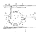
- FIG. 2 is a sectional view taken along line II-II in FIG. It is the perspective view which showed the structure of the magnet typically. It is the sectional side view which showed the structure of the magnet typically. It is the sectional side view which showed typically the structure of the substrate drying apparatus in the state which moved the magnet to the outer side of the wafer. It is the sectional side view which showed typically the structure of the board
- a substrate processing apparatus (substrate drying apparatus) according to an embodiment of the present invention is an apparatus for cleaning and drying a wafer (substrate), and in particular, effectively prevents the generation of a watermark using a magnet.
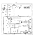
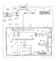
- FIG. 1 is a side sectional view schematically showing a configuration of a substrate processing apparatus according to an embodiment of the present invention
- FIG. 2 is a sectional view taken along line II-II in FIG.
- the substrate processing apparatus according to the present embodiment includes a processing chamber 1 having a hollow and substantially rectangular parallelepiped shape. As shown in FIG. 2, the processing chamber 1 is provided with a loading / unloading port 11 for loading and unloading the wafer W into the processing space in the processing chamber 1. By closing the loading / unloading port 11 with the door body 12, the processing space can be sealed.
- the spin chuck 2 Inside the processing chamber 1 is provided a spin chuck 2 that holds and rotates a substantially disc-shaped wafer W substantially horizontally.
- the spin chuck 2 includes a table unit 21 on which the wafer W is placed. As shown in FIG. 2, the table portion 21 is provided with three holding members 22 at the top, and holds the wafer W substantially horizontally by bringing the holding members 22 into contact with the three peripheral portions of the wafer W, respectively. It is configured.
- the table portion 21 includes a rotation shaft 23 protruding downward from a substantially central portion thereof, and a lower end portion of the rotation shaft 23 is connected to a motor 24 that rotates the table portion 21 about a rotation center axis in a substantially vertical direction. Yes.
- the wafer W rotates integrally with the table portion 21 in a substantially horizontal plane with the approximate center of the wafer W as the rotation center.
- the wafer W is rotated counterclockwise in plan view.
- the driving of the motor 24 is controlled by the control unit 7.
- a liquid supply means 3 for supplying a cleaning liquid is provided in the upper portion of the processing chamber 1.
- the liquid supply means 3 is provided with a nozzle 31 for supplying a cleaning chemical and a rinse liquid (a liquid having diamagnetism) to the wafer W.
- the chemical liquid is, for example, dilute hydrofluoric acid (DHF), and the rinse liquid is, for example, pure water (DIW).
- the nozzle 31 is supported by a nozzle arm 33.
- the nozzle arm 33 is provided above the wafer W supported by the spin chuck 2.
- the base end portion of the nozzle arm 33 is supported so as to be movable along a guide rail 32 arranged substantially horizontally. Further, a drive mechanism 34 that moves the nozzle arm 33 along the guide rail 32 is provided.
- the nozzle arm 33 By driving the drive mechanism 34, the nozzle arm 33 can move between the upper side of the wafer W held by the spin chuck 2 and the outer side of the periphery of the wafer W (left side in FIG. 1). Further, as the nozzle arm 33 moves, the nozzle 31 is configured to move relative to the wafer W from substantially above the center of the wafer W toward above the peripheral edge.
- the operation of the drive mechanism 34 is controlled by the control unit 7.
- the nozzle 31 is attached to the lower end of an elevating shaft 36 that projects downward from a nozzle elevating mechanism 35 fixed to the lower surface of the tip of the nozzle arm 33.
- the elevating shaft 36 can be moved up and down by the nozzle elevating mechanism 35, whereby the nozzle 31 is raised and lowered to an arbitrary height.
- the drive of the nozzle lifting mechanism 35 is controlled by the control unit 7.
- the nozzle 31 is connected to a chemical liquid supply path 37b connected to the chemical liquid supply source 37a and a rinse liquid supply path 38b connected to the rinse liquid supply source 38a.
- On-off valves 37c and 38c are provided in the chemical liquid supply path 37b and the rinse liquid supply path 38b, respectively. The opening / closing operation of each on-off valve 37c, 38c is controlled by the control unit 7.
- the substrate processing apparatus also includes a magnet 4 for moving the liquid adhering to the wafer W by a magnetic force, and a magnet transfer unit 5 for moving the magnet 4 along the wafer W toward the edge of the wafer W.
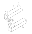
- FIG. 3 is a perspective view schematically showing the configuration of the magnet 4
- FIG. 4 is a side cross-sectional view schematically showing the configuration of the magnet 4.
- the magnet 4 has a pair of first magnet 41 and second magnet 42.
- the first magnet 41 and the second magnet 42 are electromagnets each having a quadrangular pyramid-shaped magnetic pole with a tip portion cut away, and the magnetic poles of the first magnet 41 and the second magnet 42 are counter electrodes.
- the first magnet 41 has a hole 41 a for providing a dry gas supply nozzle 6 to be described later, which opens in the opposing direction of the first magnet 41 and the second magnet 42.
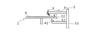
- the magnet transport unit 5 is provided substantially perpendicular to the first arm portion 51 and the second arm portion 52 that hold the magnet 4 and the bottom surface of the processing chamber 1, and supports the first and second arm portions 51 and 52.
- the first arm portion 51 has a prismatic shape, and is attached to the column 53 above the table portion 21 with the longitudinal direction being substantially horizontal. Further, the first arm portion 51 holds the first magnet 41 on the lower surface of the tip portion so that the magnetic pole of the first magnet 41 faces obliquely downward.
- the second arm portion 52 has a prismatic shape similar to that of the first arm portion 51, and is attached to the column 53 below the table portion 21 with the longitudinal direction being substantially horizontal.
- the tip end portion of the second magnet 42 faces obliquely upward, and the facing direction of the first magnet 41 and the second magnet 42 is not parallel to the wafer W held on the table portion 21.
- the second magnet 42 is held on the upper surface of the tip.
- the elevating mechanism 54 is a mechanism that elevates and lowers the first and second arm portions 51 and 52 so that the first magnet 41 and the second magnet 42 approach and separate from each other, and is configured by, for example, a linear motor.
- the linear motor includes, for example, a shaft provided along the support column 53, a cylindrical slider provided on each of the first and second arm portions 51 and 52, and mounted movably along the shaft.
- the shaft has a structure in which N poles and S poles are alternately arranged along the transport direction.
- the slider has a casing made of a non-magnetic material, and an electromagnet arranged so as to surround the shaft is built in the casing.
- the first and second arm portions 51 and 52 can be moved up and down by supplying a current to the coil constituting the electromagnet.
- the operation of the elevating mechanism 54 is controlled by the control unit 7.
- the support conveyance mechanism 55 is arranged along the radial direction so that the first magnet 41 and the second magnet 42 reciprocate between the substantially central portion of the wafer W held by the spin chuck 2 and the radial outside.
- This is a mechanism for linearly reciprocating the column 53, and is constituted by, for example, a linear motor.
- the operation of the column conveying mechanism 55 is controlled by the control unit 7.
- the substrate processing apparatus also includes a dry gas supply nozzle 6 for supplying a dry gas to the wafer W.
- the first magnet 41 has a hole 41a that opens in the facing direction, and the dry gas supply nozzle 6 is inserted into the hole 41a.
- a dry gas supply path 61 connected to a dry gas supply source 63 is connected to the dry gas supply nozzle 6.
- An open / close valve 62 is provided in the dry gas supply path 61. The opening / closing operation of the opening / closing valve 62 is controlled by the control unit 7.
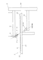
- FIG. 5 is a side sectional view schematically showing the configuration of the substrate drying apparatus in a state where the magnet 4 is moved to the outside of the wafer W
- FIG. 6 is a diagram of the substrate drying apparatus in a state where the magnet 4 is separated. It is the sectional side view which showed the structure typically.
- FIG. 7A to 7E are explanatory views conceptually showing the substrate drying method
- FIG. 8 is a flowchart showing a processing procedure of the control unit 7.
- the controller 7 moves the magnet 4 to the outer side in the radial direction of the wafer W (step S11), and separates the first magnet 41 and the second magnet 42 (step S12).
- control unit 7 moves the first magnet 41 and the second magnet 42 to a substantially central portion of the wafer W (step S13). And the control part 7 increases the rotational speed of the spin chuck 2 (step S14).
- the control unit 7 causes the first magnet 41 and the second magnet 42 to approach each other (step S15).
- the control unit opens the on-off valve 62 and supplies the dry gas to the wafer W.
- the control unit 7 moves the first magnet 41 and the second magnet 42 outward in the radial direction of the wafer W (step S16).
- the control unit 7 stops the spin chuck 2 (step S17) and ends the process.
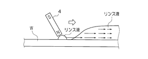
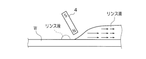
- the white arrow is the moving direction of the magnet 4
- the thin line arrow is the magnetic force related to diamagnetism acting on the rinse liquid.
- the minute droplets of the rinse liquid remaining on the wafer W can be reduced.
- the wafer W held on the spin chuck 2 is rotated, and the magnet 4 is moved radially outward from the substantially central portion of the wafer W, so that the rinse liquid is removed from the wafer W without leaving a minute droplet of the rinse liquid. Can be efficiently removed and dried.
- the rotation axis 23 of the spin chuck 2 is avoided and the wafer W is approximately centered.
- the first magnet 41 and the second magnet 42 can be made to face each other and approach each other, and the rinsing liquid can be removed by applying the magnetic force of the magnet 4 to the central portion.
- the rinse liquid can be more effectively removed from the wafer W by supplying the dry gas to the wafer W from the dry gas supply nozzle 6 provided in the first magnet 41.
- FIG. 11 is a perspective view schematically showing the configuration of the magnet 4 according to the modification.
- the magnet 104 may be configured using the Hallbach type first magnet 141 and the second magnet 142. good.
- Each of the first magnet 141 and the second magnet 142 is constituted by a half body of a hexagonal column plate.
- the Hallbach-type magnet 104 is disclosed in, for example, Japanese Patent Application Laid-Open No. 2000-243621, and detailed description thereof is omitted.
- the shape of the magnet is not limited to these, and any other shape may be used as long as it can apply a magnetic force related to diamagnetism to the rinse liquid adhering to the wafer.
- the wafer has been described as the substrate to be dried, the present invention may be applied to other substrates that require cleaning, such as glass substrates.
Landscapes
- Engineering & Computer Science (AREA)
- Health & Medical Sciences (AREA)
- Life Sciences & Earth Sciences (AREA)
- Molecular Biology (AREA)
- Mechanical Engineering (AREA)
- General Engineering & Computer Science (AREA)
- Cleaning Or Drying Semiconductors (AREA)
- Drying Of Solid Materials (AREA)
Abstract
Description
ウエハにIPAガスが吹き付けられると、ウエハ上の水表面にIPAガスが局所的に溶解し、濃度差マランゴニ対流が発生する。このため、気液界面における水の流れが発生し、水滴から微小液滴が分離して微小液滴が発生することを防止することができる。
基板に付着した液体に働く反磁性に係る磁力は、液体全体に働くため、微小液滴も該磁力によって基板の縁側へ移動する。また、基板に付着した大きな液滴が基板の縁側へ移動する際に、微小液滴が取り残されることがあるが、基板の縁側へ移動する磁石が取り残された微小液滴に接近した場合、基板の縁側へ移動した大きな液滴よりも、取り残された該微小液滴に対して大きな磁力が働く。このため、微小液滴を大きな液滴の方へ押し戻すように移動させ、該液滴に取り込ませることが可能である。従って、従来のマランゴニ乾燥に比べて、基板に残留する微小液滴を減少させることが可能である。
ノズルアーム33は、スピンチャック2に支持されたウエハWの上方に備えられている。ノズルアーム33の基端部は、略水平に配置されたガイドレール32に沿って移動自在に支持されている。また、ガイドレール32に沿ってノズルアーム33を移動させる駆動機構34が備えられている。駆動機構34の駆動により、ノズルアーム33は、スピンチャック2に保持されたウエハWの上方とウエハWの周縁より外側(図1においては左側)との間で移動することができる。また、ノズルアーム33の移動に伴って、ノズル31がウエハWの略中心部上方から周縁部上方に向かってウエハWと相対的に移動するように構成されている。駆動機構34の動作は制御部7によって制御される。
そして、制御部7は、図7Dに示すように、第1磁石41及び第2磁石42をウエハWの径方向外側へ移動させる(ステップS16)。第1磁石41及び第2磁石42をウエハWの略中央部から径方向外側へ移動させることによって、ウエハW上にリンス液の微小液滴が残留することを効果的に防止される。図7Eに示すように、第1磁石41及び第2磁石42がウエハWの径方向外側まで移動した場合、制御部7は、スピンチャック2を停止させ(ステップS17)、処理を終える。
また、図10Aに示すように、スピンチャック2の回転による遠心力によってウエハWに付着したリンス液の液滴がウエハWの縁側へ移動する際に、リンス液の微小液滴が取り残されることがある。ところが、磁石4をウエハWに沿って縁側へ移動させ、磁石4を微小液滴に接近させた場合、図10Bに示すように、微小液滴を大きなリンス液滴の方へ押し戻すように移動させ、該リンス液滴に取り込ませることが可能である。ウエハWに付着したリンス液に働く反磁性に係る磁力は、リンス液全体に働くため、微小液滴もウエハWの縁側へ移動させることができる。また、取り残された微小液滴に磁石4が接近すると、該微小液滴に大きな磁力が働き、微小液滴を、大きなリンス液滴の方へ押し戻すことができる。従って、従来のマランゴニ乾燥に比べて、ウエハWに残留するリンス液の微小液滴を減少させることができる。
図11は、変形例に係る磁石4の構成を模式的に示した斜視図である。上述の実施の形態にあっては、ポールピース型の磁石4を説明したが、図11に示すようにホールバッハ型の第1磁石141及び第2磁石142を用いて磁石104を構成しても良い。第1磁石141及び第2磁石142はそれぞれ、六角柱板の半体によって構成される。ホールバッハ型の磁石104は、例えば特開2000-243621号公報に開示されているため、詳細な説明は省略する。
2 スピンチャック
3 液体供給手段
4 磁石
5 磁石搬送部(磁石搬送手段)
6 乾燥ガス供給ノズル
7 制御部
41 第1磁石
41a 孔部
42 第2磁石
51 支柱
52 第1腕部
53 第2腕部
54 昇降機構
55 支柱搬送機構(搬送機構)
W ウエハ
Claims (9)
- 反磁性を有する液体で洗浄された基板を乾燥させる基板乾燥装置において、
基板に付着した液体を磁力によって移動させるための磁石と、
該磁石を、基板に沿って該基板の縁側へ移動させる磁石搬送手段と
を備えることを特徴とする基板乾燥装置。 - 円板状の基板を保持して回転させるスピンチャックを備え、
前記磁石搬送手段は、
前記磁石を基板に沿って、該基板の略中央部から径方向外側へ移動させる搬送機構を備える
ことを特徴とする請求項1に記載の基板乾燥装置。 - 前記磁石は、
互いの磁極が対極となるように対向配置された第1磁石及び第2磁石を有し、該第1磁石及び第2磁石の対向方向は前記スピンチャックに保持された基板に対して非平行である
ことを特徴とする請求項2に記載の基板乾燥装置。 - 前記第1磁石及び第2磁石を接近及び離反させる接離手段を備える
ことを特徴とする請求項3に記載の基板乾燥装置。 - 前記接離手段は、
前記第1磁石及び第2磁石を前記基板の略中央部で接近させる手段を備える
ことを特徴とする請求項4に記載の基板乾燥装置。 - 前記スピンチャックに保持された基板の一面側に前記第1磁石が対向し、前記第2磁石が該基板の他面側に対向するように各磁石を保持する腕部と、
該腕部を支持する支柱と
を備え、
前記接離手段は、
前記支柱に沿って前記腕部を昇降させる昇降機構を備える
ことを特徴とする請求項4又は請求項5に記載の基板乾燥装置。 - 基板に乾燥ガスを供給する乾燥ガス供給ノズルを備え、
前記第1磁石は、前記対向方向に開口した孔部を有し、前記乾燥ガス供給ノズルは該孔部に挿嵌されている
ことを特徴とする請求項3乃至請求項6のいずれか一つに記載の基板乾燥装置。 - 反磁性を有する液体で洗浄された基板を乾燥させる基板乾燥方法において、
基板に付着した液体を磁力によって移動させるための磁石を、基板に接近させ、
該磁石を前記基板に沿って該基板の縁側へ移動させる
ことを特徴とする基板乾燥方法。 - 反磁性を有する液体で洗浄された基板を乾燥させる基板乾燥方法において、
円板状の基板を回転させ、
基板に付着した液体を磁力によって移動させるための磁石を、前記基板の略中央部に接近させ、
該磁石を基板に沿って、該基板の略中央部から径方向外側へ移動させる
ことを特徴とする基板乾燥方法。
Priority Applications (2)
| Application Number | Priority Date | Filing Date | Title |
|---|---|---|---|
| CN2010800472286A CN102576670A (zh) | 2009-12-25 | 2010-12-07 | 基板干燥装置以及基板干燥方法 |
| US13/518,631 US20120255193A1 (en) | 2009-12-25 | 2010-12-07 | Substrate drying apparatus and method |
Applications Claiming Priority (2)
| Application Number | Priority Date | Filing Date | Title |
|---|---|---|---|
| JP2009295503A JP2011135009A (ja) | 2009-12-25 | 2009-12-25 | 基板乾燥装置及び基板乾燥方法 |
| JP2009-295503 | 2009-12-25 |
Publications (1)
| Publication Number | Publication Date |
|---|---|
| WO2011077937A1 true WO2011077937A1 (ja) | 2011-06-30 |
Family
ID=44195472
Family Applications (1)
| Application Number | Title | Priority Date | Filing Date |
|---|---|---|---|
| PCT/JP2010/071855 Ceased WO2011077937A1 (ja) | 2009-12-25 | 2010-12-07 | 基板乾燥装置及び基板乾燥方法 |
Country Status (5)
| Country | Link |
|---|---|
| US (1) | US20120255193A1 (ja) |
| JP (1) | JP2011135009A (ja) |
| KR (1) | KR20120092719A (ja) |
| CN (1) | CN102576670A (ja) |
| WO (1) | WO2011077937A1 (ja) |
Cited By (1)
| Publication number | Priority date | Publication date | Assignee | Title |
|---|---|---|---|---|
| US20120255193A1 (en) * | 2009-12-25 | 2012-10-11 | Tokyo Electron Limited | Substrate drying apparatus and method |
Families Citing this family (5)
| Publication number | Priority date | Publication date | Assignee | Title |
|---|---|---|---|---|
| JP6426924B2 (ja) * | 2013-09-30 | 2018-11-21 | 芝浦メカトロニクス株式会社 | 基板処理装置及び基板処理方法 |
| JP6614610B2 (ja) | 2016-02-12 | 2019-12-04 | 株式会社Screenホールディングス | 基板処理装置 |
| CN110307698B (zh) * | 2018-03-27 | 2020-10-23 | 创意电子股份有限公司 | 烘干设备 |
| KR102857974B1 (ko) | 2021-08-12 | 2025-09-11 | 삼성전자주식회사 | 기판 회전 장치, 이를 포함하는 기판 처리 장치 및 이를 이용한 기판 처리 방법 |
| KR102846205B1 (ko) * | 2024-04-09 | 2025-08-13 | 성균관대학교산학협력단 | 기판 세정 장치 및 방법 |
Citations (2)
| Publication number | Priority date | Publication date | Assignee | Title |
|---|---|---|---|---|
| JP2001044165A (ja) * | 1999-05-26 | 2001-02-16 | Tokyo Electron Ltd | 基板処理方法及び基板処理装置 |
| JP2003280218A (ja) * | 2002-03-27 | 2003-10-02 | Dainippon Screen Mfg Co Ltd | 基板処理方法および基板処理装置 |
Family Cites Families (19)
| Publication number | Priority date | Publication date | Assignee | Title |
|---|---|---|---|---|
| BE756149A (fr) * | 1969-09-15 | 1971-02-15 | Ncr Co | Support d'enregistrement magnetique |
| US4595440A (en) * | 1983-12-08 | 1986-06-17 | Memron Inc. | Transfer process for forming magnetic disk memories |
| US4571850A (en) * | 1984-05-17 | 1986-02-25 | The Fluorocarbon Company | Centrifugal wafer processor |
| US5242803A (en) * | 1987-07-17 | 1993-09-07 | Martin Marietta Energy Systems, Inc. | Rotor assembly and assay method |
| US5105556A (en) * | 1987-08-12 | 1992-04-21 | Hitachi, Ltd. | Vapor washing process and apparatus |
| DE3918559A1 (de) * | 1989-06-07 | 1990-12-13 | Hoechst Ag | Verfahren und vorrichtung zum elektrostatischen aufspruehen einer fluessigkeitsschicht auf ein substrat und zum trocknen der fluessigkeitsschicht auf dem substrat |
| US5813133A (en) * | 1996-09-04 | 1998-09-29 | Minnesota Mining And Manufacturing Company | Coated substrate drying system with magnetic particle orientation |
| US5705822A (en) * | 1997-01-30 | 1998-01-06 | Vanguard International Semiconductor Corporation | Cooling system for semiconductor process |
| DE19721689C2 (de) * | 1997-05-23 | 1999-06-10 | Steag Hama Tech Gmbh Machines | Vorrichtung zum Trocknen von Substraten |
| JP2004529929A (ja) * | 2001-04-23 | 2004-09-30 | ニュクリスト ファーマシューティカルズ コーポレーション | アポトーシスの誘導およびマトリックスメタロプロテイナーゼの阻害のための金属の使用 |
| FR2824001B1 (fr) * | 2001-04-26 | 2003-10-10 | Bio Merieux | Procede de depot d'un spot d'un produit d'interet, et application pour l'isolement et/ou la determination d'un analyte |
| US20050153107A1 (en) * | 2004-01-12 | 2005-07-14 | Tdk Corporation | Substrate having functional layer pattern formed thereon and method of forming functional layer pattern |
| TWI286353B (en) * | 2004-10-12 | 2007-09-01 | Tokyo Electron Ltd | Substrate processing method and substrate processing apparatus |
| EP2400039A3 (en) * | 2005-04-30 | 2012-11-07 | Jae-Chern Yoo | Bio-Disc, Bio-Driver Apparatus, And Assay Method Using the Same |
| CN101165854A (zh) * | 2006-10-19 | 2008-04-23 | 大日本网目版制造株式会社 | 基板处理装置和基板处理方法 |
| JP4886544B2 (ja) * | 2007-02-09 | 2012-02-29 | 大日本スクリーン製造株式会社 | 基板処理方法および基板処理装置 |
| US8067176B2 (en) * | 2008-01-25 | 2011-11-29 | Shimadzu Corporation | Microchemistry reaction method |
| JP2011135009A (ja) * | 2009-12-25 | 2011-07-07 | Tokyo Electron Ltd | 基板乾燥装置及び基板乾燥方法 |
| US9250017B2 (en) * | 2012-03-16 | 2016-02-02 | Jerry D. Miller | Magnet supported rotary drum dryer |
-
2009
- 2009-12-25 JP JP2009295503A patent/JP2011135009A/ja active Pending
-
2010
- 2010-12-07 CN CN2010800472286A patent/CN102576670A/zh active Pending
- 2010-12-07 WO PCT/JP2010/071855 patent/WO2011077937A1/ja not_active Ceased
- 2010-12-07 US US13/518,631 patent/US20120255193A1/en not_active Abandoned
- 2010-12-07 KR KR1020127018778A patent/KR20120092719A/ko not_active Ceased
Patent Citations (2)
| Publication number | Priority date | Publication date | Assignee | Title |
|---|---|---|---|---|
| JP2001044165A (ja) * | 1999-05-26 | 2001-02-16 | Tokyo Electron Ltd | 基板処理方法及び基板処理装置 |
| JP2003280218A (ja) * | 2002-03-27 | 2003-10-02 | Dainippon Screen Mfg Co Ltd | 基板処理方法および基板処理装置 |
Cited By (1)
| Publication number | Priority date | Publication date | Assignee | Title |
|---|---|---|---|---|
| US20120255193A1 (en) * | 2009-12-25 | 2012-10-11 | Tokyo Electron Limited | Substrate drying apparatus and method |
Also Published As
| Publication number | Publication date |
|---|---|
| KR20120092719A (ko) | 2012-08-21 |
| JP2011135009A (ja) | 2011-07-07 |
| CN102576670A (zh) | 2012-07-11 |
| US20120255193A1 (en) | 2012-10-11 |
Similar Documents
| Publication | Publication Date | Title |
|---|---|---|
| TWI626090B (zh) | 基板保持旋轉裝置及具備其之基板處理裝置、暨基板處理方法 | |
| TWI686897B (zh) | 基板保持旋轉裝置及具備其之基板處理裝置、以及基板處理方法 | |
| CN111524839B (zh) | 基板处理装置 | |
| JP7282494B2 (ja) | 基板処理装置および基板処理方法 | |
| US10192771B2 (en) | Substrate holding/rotating device, substrate processing apparatus including the same, and substrate processing method | |
| KR101911144B1 (ko) | 기판 유지 회전 장치 및 그것을 구비한 기판 처리 장치, 그리고 기판 처리 방법 | |
| JP6945314B2 (ja) | 基板処理装置 | |
| WO2011077937A1 (ja) | 基板乾燥装置及び基板乾燥方法 | |
| JP5973299B2 (ja) | 基板処理装置 | |
| JP2017147408A (ja) | 基板処理装置および基板処理方法 | |
| JP5973300B2 (ja) | 基板処理装置 | |
| CN106252199A (zh) | 基板处理方法以及基板处理装置 | |
| JP6292934B2 (ja) | 基板処理装置 | |
| KR102616246B1 (ko) | 처리액을 공급 및 회수하는 기판 처리 장치 | |
| JP2009224514A (ja) | 基板処理装置および基板処理方法 | |
| JP6562508B2 (ja) | 基板保持装置 | |
| JP6562507B2 (ja) | 基板保持装置およびこれを備える基板処理装置 | |
| JP6294121B2 (ja) | 基板処理装置 | |
| JP6230941B2 (ja) | 基板処理装置 | |
| JP5379663B2 (ja) | 基板処理方法および基板処理装置 | |
| JP7700008B2 (ja) | 基板処理装置および基板処理方法 | |
| JP5936505B2 (ja) | 基板処理装置 | |
| KR20230053155A (ko) | 기판 처리 장치 및 기판 처리 방법 | |
| JP2004319880A (ja) | 基板処理装置 |
Legal Events
| Date | Code | Title | Description |
|---|---|---|---|
| WWE | Wipo information: entry into national phase |
Ref document number: 201080047228.6 Country of ref document: CN |
|
| 121 | Ep: the epo has been informed by wipo that ep was designated in this application |
Ref document number: 10839171 Country of ref document: EP Kind code of ref document: A1 |
|
| NENP | Non-entry into the national phase |
Ref country code: DE |
|
| WWE | Wipo information: entry into national phase |
Ref document number: 13518631 Country of ref document: US |
|
| ENP | Entry into the national phase |
Ref document number: 20127018778 Country of ref document: KR Kind code of ref document: A |
|
| 122 | Ep: pct application non-entry in european phase |
Ref document number: 10839171 Country of ref document: EP Kind code of ref document: A1 |