WO2011077822A1 - Half precast floor plank, and slab construction method using same - Google Patents
Half precast floor plank, and slab construction method using same Download PDFInfo
- Publication number
- WO2011077822A1 WO2011077822A1 PCT/JP2010/068632 JP2010068632W WO2011077822A1 WO 2011077822 A1 WO2011077822 A1 WO 2011077822A1 JP 2010068632 W JP2010068632 W JP 2010068632W WO 2011077822 A1 WO2011077822 A1 WO 2011077822A1
- Authority
- WO
- WIPO (PCT)
- Prior art keywords
- floor
- side plates
- slab
- bottom plate
- members
- Prior art date
Links
Images

Classifications
-
- E—FIXED CONSTRUCTIONS
- E04—BUILDING
- E04B—GENERAL BUILDING CONSTRUCTIONS; WALLS, e.g. PARTITIONS; ROOFS; FLOORS; CEILINGS; INSULATION OR OTHER PROTECTION OF BUILDINGS
- E04B5/00—Floors; Floor construction with regard to insulation; Connections specially adapted therefor
-
- E—FIXED CONSTRUCTIONS
- E04—BUILDING
- E04B—GENERAL BUILDING CONSTRUCTIONS; WALLS, e.g. PARTITIONS; ROOFS; FLOORS; CEILINGS; INSULATION OR OTHER PROTECTION OF BUILDINGS
- E04B5/00—Floors; Floor construction with regard to insulation; Connections specially adapted therefor
- E04B5/16—Load-carrying floor structures wholly or partly cast or similarly formed in situ
- E04B5/32—Floor structures wholly cast in situ with or without form units or reinforcements
- E04B5/36—Floor structures wholly cast in situ with or without form units or reinforcements with form units as part of the floor
- E04B5/38—Floor structures wholly cast in situ with or without form units or reinforcements with form units as part of the floor with slab-shaped form units acting simultaneously as reinforcement; Form slabs with reinforcements extending laterally outside the element
- E04B5/40—Floor structures wholly cast in situ with or without form units or reinforcements with form units as part of the floor with slab-shaped form units acting simultaneously as reinforcement; Form slabs with reinforcements extending laterally outside the element with metal form-slabs
-
- E—FIXED CONSTRUCTIONS
- E04—BUILDING
- E04B—GENERAL BUILDING CONSTRUCTIONS; WALLS, e.g. PARTITIONS; ROOFS; FLOORS; CEILINGS; INSULATION OR OTHER PROTECTION OF BUILDINGS
- E04B5/00—Floors; Floor construction with regard to insulation; Connections specially adapted therefor
- E04B5/16—Load-carrying floor structures wholly or partly cast or similarly formed in situ
- E04B5/32—Floor structures wholly cast in situ with or without form units or reinforcements
- E04B5/36—Floor structures wholly cast in situ with or without form units or reinforcements with form units as part of the floor
- E04B5/38—Floor structures wholly cast in situ with or without form units or reinforcements with form units as part of the floor with slab-shaped form units acting simultaneously as reinforcement; Form slabs with reinforcements extending laterally outside the element
-
- E—FIXED CONSTRUCTIONS
- E04—BUILDING
- E04B—GENERAL BUILDING CONSTRUCTIONS; WALLS, e.g. PARTITIONS; ROOFS; FLOORS; CEILINGS; INSULATION OR OTHER PROTECTION OF BUILDINGS
- E04B5/00—Floors; Floor construction with regard to insulation; Connections specially adapted therefor
- E04B5/16—Load-carrying floor structures wholly or partly cast or similarly formed in situ
- E04B5/32—Floor structures wholly cast in situ with or without form units or reinforcements
- E04B5/36—Floor structures wholly cast in situ with or without form units or reinforcements with form units as part of the floor
Definitions
- the present invention relates to a half precast slab mainly applied to a turbine mount of a power plant and other parts having a large slab thickness, and a slab construction method using the same.
- precast construction methods are widely used to construct reinforced concrete structures by bringing factory-made reinforced concrete members to the site, installing them in place, and joining adjacent parts together. It has been adopted.
- the precast method is broadly divided into so-called full precast, which precasts the entire member, and half precast, which corresponds to part of the member precast and the rest of the concrete is placed on site.
- full precast which precasts the entire member
- half precast which corresponds to part of the member precast and the rest of the concrete is placed on site.
- the half precast method When the half precast method is applied to the floor, if it is on-site concrete, the part corresponding to the bottom formwork is prefabricated as a precast floor slab, and this is transported to the site and bridged to the beam. After placing the bars, it is common to cast concrete on a precast floor slab to integrate them into a composite floor slab.
- This half precast method eliminates the need for a bottom formwork for building slabs, and allows you to enjoy the original benefits of precasting, and also facilitates handling when transporting and assembling due to weight reduction. Become.
- a turbine gantry when a gantry for installing a turbine (hereinafter simply referred to as a turbine gantry) is constructed of reinforced concrete, in order to sufficiently withstand the weight and vibration, it is necessary to make the slab a high strength and high rigidity,
- the thickness is 1 m or more, and a large diameter reinforcing bar such as D32 is used as the main reinforcing bar.
- the present invention has been made in consideration of the above-described circumstances, and an object thereof is to provide a half precast floor slab capable of being half precast even for a slab having a large thickness, and a slab construction method using the same. .
- a half precast floor slab according to the present invention is a floor formwork comprising a long bottom plate and a pair of side plates erected on a longitudinal edge of the bottom plate as described in claim 1.
- the members are continuously arranged along the direction orthogonal to the material axes and parallel to each other, and among the floor mold members that are continuously provided, the side plate and the other of the floor mold members adjacent to each other
- Each floor form frame member is connected along a direction perpendicular to the material axis so that the side plate of the floor form frame member comes into contact, and among the side plates, the side plate excluding the outermost side plate
- the height is adjusted so that the inner space of each floor form member surrounded by the bottom plate and the pair of side plates standing upright communicates with each other to form a single reinforcing bar arrangement region. It is set lower than the height of the outer side plate.
- the slab construction method using the half precast floor slab according to the present invention is a floor type comprising a long bottom plate and a pair of side plates erected on a longitudinal edge of the bottom plate as described in claim 2.
- the frame members are continuously arranged along the direction orthogonal to the material axes and parallel to each other, and among the floor mold members that are arranged in series, the side plate and the other of the floor mold frame members adjacent to each other
- Each floor form frame member is connected along a direction perpendicular to the material axis so that the side plate of the floor form member comes into contact, and simultaneously with or before or after the connecting step,
- Reinforcing bars are arranged in a single reinforcing bar arrangement region in which the internal space of each floor form member surrounded by the pair of standing side plates communicates with each other, and concrete is placed in the single reinforcing bar arrangement region
- the concrete and the reinforcing bar Serial is to build a composite slab consisting of the bed frame members.
- the PC steel wire is attached to each floor form frame member along a direction perpendicular to the material axis of each floor form frame member.
- the floor mold members are connected to each other by penetrating them, introducing tension to the PC steel wires, and fixing the ends thereof with a fixing material.
- the slab construction method using the half precast slab according to the present invention is to penetrate the PC steel wire in the cross section of the bottom plate.
- the slab construction method using the half precast slab according to the present invention is to remove the fixing material or remove the fixing material and the PC steel wire after the strength of the cast concrete is expressed. .
- each of the floor formwork members is fastened by penetrating bolts to the side plates that contact each other among the side plates. They are connected to each other.
- the beam formwork applied when constructing beams for general buildings is connected in the direction perpendicular to the material axis and connected to form a slab.
- beam formwork must be firmly connected to each other, which requires a considerable amount of reinforcing material. Integration at a level that satisfies high rigidity and high strength like a turbine mount is economical. Lack of sex.
- a plurality of floor form frame members comprising a long bottom plate and a pair of side plates erected on the longitudinal edge of the bottom plate are connected to each other.
- the height of the side plate excluding the outermost side plate among the side plates of the floor mold member is set lower than the height of the outermost side plate.
- the space above the bottom plate for each floor form member is not in an independent state but is in a state of communicating with each other to form one space region.
- the inner surface of the outermost side plate is defined as a side boundary
- the virtual line connecting the top ends of the outermost side plates is defined as an upper boundary
- the upper surface of the bottom plate of each floor form member is generally defined as a lower boundary.
- a spatial region is formed.
- the synthetic slab can be integrated by the reinforcing bar, and the total required reinforcing bar amount can be constructed only by on-site placement. It will be roughly equal to the amount of reinforcing bars that will be required.
- the integration required as a slab is possible with the reinforcing bars arranged in a single reinforcing bar arrangement area, so that the floor formwork members are integrated so that they can only withstand the load when placing concrete. If it becomes, it is enough.
- the half precast slab and the slab construction method using the same according to the present invention can be widely applied to a slab having a large thickness, particularly a slab requiring high rigidity and high strength. It can be widely used not only for power plants and other special buildings, but also for office buildings, factories and other general buildings.
- the floor mold member has a J-shaped cross section in which a high side plate and a low side plate are erected on the long edge of the bottom plate, and a U-shaped cross section in which the low side plate is erected on the long edge of the bottom plate.
- the J-shaped cross-section type floor form frame member is arranged on the outermost side, and the U-shaped cross-section type is placed between them.
- a floor formwork member is arranged.
- the J-shaped cross section is such that the high side plate is on the outside
- the floor type frame members of the type are symmetrically arranged opposite to each other, the number of member of the floor type frame member of U-shaped cross-section type is 1, and the number of members of the floor type frame member of J-shaped cross-section type is 2
- the number of members of the U-shaped cross-section type floor form member may be appropriately increased according to the size of the slab.
- the floor form frame member has a prestressed structure in which tension is introduced into a PC steel wire embedded in the bottom plate along the material axis direction, thereby increasing the bending rigidity around the direction perpendicular to the material axis.
- the side plate erected on the bottom plate also contributes to the improvement of the bending stiffness around the direction perpendicular to the material axis as a stiffening rib.
- the method of connecting the floor form members in the direction perpendicular to the material axis is arbitrary, and a PC steel wire or a PC steel rod can be used as appropriate.
- the PC steel wire is connected to each floor.
- Each floor formwork is disposed by penetrating each floor formwork member along a direction perpendicular to the material axis of the formwork member, introducing tension to the PC steel wire and fixing the ends thereof with a fixing material.
- a method of connecting the members to each other or a method of connecting the floor frame members to each other by passing the bolts through the side plates contacting each other and fastening them can be considered.
- the PC steel wire and the fixing material are temporary materials for integrating the floor formwork members so as to withstand the concrete load at the time of placing the concrete, after the concrete strength is expressed, only the fixing material is used.
- the PC steel wire may be removed together with the fixing material. Incidentally, if the fixing material is removed, the fixing material can be prevented from being exposed from the side of the slab.
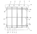
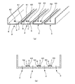
- the top view of half precast floor slab 1 similarly.
- the bottom plate upper spaces 31 and 32 of the floor frame members 2 and 3 communicate with each other in the horizontal direction, and as a result, a single reinforcing bar arrangement region 33 is formed.
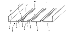
- FIG. 1 is an overall perspective view showing a half precast slab according to the present embodiment
- FIG. 2 is a plan view of the same.
- the half precast floor slab 1 according to the present embodiment is configured by using a floor form frame member 2 and a floor form frame member 3, and the floor form frame member 2 has a long shape.
- the floor plate member 3 is composed of a bottom plate 4 and a pair of side plates 5 and 5 erected on the longitudinal edge of the bottom plate.
- the floor frame member 3 is also a long bottom plate 6 and a longitudinal edge of the bottom plate, like the floor frame member 2.
- the side plate 5 and the side plate 7 have their height set lower than that of the side plate 8, and the floor form frame member 2 has a U-shaped cross section as a whole.
- the floor mold member 3 has a J-shaped cross section as a whole.
- the half precast floor slab 1 has two floor mold members 2, 2 connected in a direction perpendicular to the material axis and parallel to each other so that their side plates 5, 5 are in contact with each other.
- the floor mold frame members 3 are connected in series so as to be parallel to each other in the direction perpendicular to the material axis of the floor mold frame member 2 so that the side plate 7 contacts the side plate 5 located on the opposite side of the frame member, These are connected to each other by fastening with a PC steel wire 9 along the direction perpendicular to the material axis.
- the heights H1 of the side plates excluding the outermost side plate 8, that is, the side plate 5 and the side plate 7, are shown in FIG.
- the bottom plate upper spaces 32, 32 are set lower than the height H2 of the outermost side plate 8 so that a single reinforcing bar arrangement region 33 is formed by communicating with each other in the horizontal direction.
- the floor mold members 2 and 3 are set to have a width of 3,500 mm, a length in the material axis direction of 10,000 mm, and a thickness of 200 mm, and the height H2 of the side plate 8 is 1,500 mm, the side plate 5 and the side plate 7.
- the height H1 is set to about 200 mm to 300 mm, for example.
- the synthetic slab constructed using the half precast floor slab 1 composed of such floor mold members 2 and 3 has a thickness of 1,500 mm.
- the two floor mold members 2, 2 and the two floor mold members 3, 3 are orthogonal to their material axes. Are connected to the existing beams, columns or walls 21 and 21 so as to be parallel to each other as described above (see FIG. 2).
- each floor frame member 2 and 3 are fastened with a PC steel wire 9 along a direction perpendicular to their material axes.
- a sealing material (not shown) is arranged between the side plate 7 of the floor mold member 3 and the side plate 5 of the floor mold member 2, and the sealing material is Preferably, the side plates 5 and 7 are brought into contact with each other.
- a sealing material (not shown) between the side plates 5 and 5 of the floor form members 2 and 2 so that the side plates 5 and 5 are brought into contact with each other through the sealing material.
- the bottom plate upper space 31 of the floor mold member 3 and the bottom plate upper space 32 of the floor mold member 2 are not in an independent state but communicated with each other as described in FIG.
- the bottom plate 6 and the floor frame of the floor frame member 3 are in a state where the inner surfaces of the outermost side plates 8 and 8 are defined as side boundaries and the virtual line 34 connecting the top ends of the outermost side plates 8 is defined as an upper boundary. Since a space area having the upper surface of the bottom plate 4 of the member 2 as a generally lower boundary is formed as the reinforcing bar arrangement area 33, the reinforcing bars are arranged in the reinforcing bar arrangement area 33.
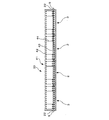
- FIG. 4 shows a state in which the reinforcing bar 41 is arranged in the reinforcing bar arrangement region 33.
- the reinforcing bar 41 includes an upper reinforcing bar 42, a lower reinforcing bar 43, and a shear reinforcing bar 44, but the reinforcing bar arrangement region 33 includes the space above the bottom plate 31 of the floor frame member 3 and the floor frame member 2. Since it is an integrated space composed of the bottom plate upper space 32, the bars can be freely arranged without interfering with the floor frame members 2 and 3 from the left end to the right end of the figure.
- the reinforcing bars extending in the horizontal direction in the figure that is, the reinforcing bars extending in the direction perpendicular to the material axes of the floor form frame members 2 and 3, become important reinforcing bars for integration as a composite slab.
- the lower end bars 43 can be arranged in the horizontal direction as well as 42 and can contribute to the integration of the composite slab.
- the side plates 5 and 7 when determining the height H1 of the side plates 5 and 7, in addition to making it lower than the side plate 8, among the reinforcing bars embedded in the slab, the side plates 5 and 7 extend in the direction perpendicular to the material axis of the floor frame members 2 and 3.
- One guideline is to set it below the installation height of the bottom bar.
- reinforcing bars that greatly contribute to slab integration can be reliably arranged along the direction perpendicular to the material axes of the floor mold members 2 and 3.
- the fixing material 22 is removed after the strength of the cast concrete is developed. Further, when the PC steel wire 9 is inserted through a sheath tube (not shown) arranged in advance on the floor mold members 2 and 3, the PC steel wire 9 is also pulled out of the sheath tube and removed.
- the height of the side plate 5 and the side plate 7 excluding the outermost side plate 8 is set to the height of the outermost side plate 8. Since the height is set to be lower than the height, the bottom plate upper spaces 31 and 32 for each of the floor frame members 2 and 3 are not in an independent state but are in a state of communicating with each other in the horizontal direction to form one space region.
- the reinforcing bars as such a single reinforcing bar arrangement region 33, it is possible to reliably integrate the synthetic slab, and thus even a thick slab is required for the slab. Precasting can be achieved without reducing the strength and rigidity.
- the fixing material 22 is removed to prevent the protrusion from the floor form member 3, but if it is not necessary, the fixing material 22 may be left as it is.
- the choice of removing or leaving the line 9 is also arbitrary.
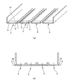
- the PC steel wire 9 is disposed so as to pass above the bottom plates 4 and 6, but instead of this, as shown in FIG. 5, the insertion formed in the cross section of the bottom plates 4 and 6 The PC steel wire 9 may be inserted into the hole 51.
- the floor form frame members 2 and 3 are fastened with the PC steel wire 9, but the configuration in which the continuous floor form frame members are connected along the direction perpendicular to the material axis is arbitrary.
- a bolt 62 is passed through a bolt hole 61 formed in the side plates 7 and 5 or the side plates 5 and 5 that are in contact with each other, and a nut 63 is screwed to the tip of the bolt.
- the floor mold members 2 and 3 may be connected to each other by being fastened together. Note that the pitch and number of bolts may be appropriately determined in consideration of the strength required for concrete placement.
Abstract
Description
Claims (6)
- 長尺状の底板及び該底板の長手縁部に立設された一対の側板からなる床型枠部材をそれらの材軸に直交する方向に沿ってかつ互いに平行になるように連設するとともに、連設された床型枠部材のうち、互いに隣り合う一方の床型枠部材の側板と他方の床型枠部材の側板とが当接されるように前記各床型枠部材をそれらの材軸に直交する方向に沿って連結してなり、前記側板のうち、最外縁の側板を除く側板の高さを、前記底板及びそれに立設された前記一対の側板で囲まれた前記各床型枠部材ごとの内部空間が互いに連通して単一の鉄筋配置領域が形成されるように、前記最外縁の側板の高さより低く設定したことを特徴とするハーフプレキャスト床版。 A floor mold frame member composed of a long bottom plate and a pair of side plates erected on the longitudinal edge of the bottom plate is continuously provided along a direction perpendicular to the material axes and parallel to each other, Among the floor mold members that are continuously provided, the respective floor mold members are arranged so that the side plates of one floor mold member adjacent to each other and the side plates of the other floor mold member are brought into contact with each other. The floor molds are connected along a direction orthogonal to the floor plate, and the height of the side plates excluding the outermost side plate among the side plates is surrounded by the bottom plate and the pair of side plates provided upright thereto. A half precast slab characterized by being set lower than the height of the outermost side plate so that the internal space of each member communicates with each other to form a single reinforcing bar arrangement region.
- 長尺状の底板及び該底板の長手縁部に立設された一対の側板からなる床型枠部材をそれらの材軸に直交する方向に沿ってかつ互いに平行になるように連設し、
連設された床型枠部材のうち、互いに隣り合う一方の床型枠部材の側板と他方の床型枠部材の側板とが当接されるように前記各床型枠部材をそれらの材軸に直交する方向に沿って連結し、
該連結工程と同時に又は相前後して、前記底板及びそれに立設された前記一対の側板で囲まれた前記各床型枠部材ごとの内部空間が互いに連通してなる単一の鉄筋配置領域に鉄筋を配置し、
前記単一の鉄筋配置領域にコンクリートを打設することにより、該打設コンクリートと前記鉄筋と前記各床型枠部材とからなる合成スラブを構築することを特徴とするハーフプレキャスト床版を用いたスラブ構築方法。 A floor mold frame member composed of a long bottom plate and a pair of side plates erected on the longitudinal edge of the bottom plate is continuously provided so as to be parallel to each other along a direction perpendicular to the material axes,
Among the floor mold members that are continuously provided, the respective floor mold members are arranged so that the side plates of one floor mold member adjacent to each other and the side plates of the other floor mold member are brought into contact with each other. Connected along the direction orthogonal to
Simultaneously with or before or after the connecting step, a single reinforcing bar arrangement region in which the inner space of each floor form member surrounded by the bottom plate and the pair of side plates erected on the bottom plate communicates with each other. Place the rebar,
Using a half precast slab characterized by constructing a composite slab composed of the cast concrete, the reinforcing bar and each floor formwork member by casting concrete in the single reinforcing bar arrangement region Slab construction method. - 前記連結工程において、PC鋼線を前記各床型枠部材の材軸に直交する方向に沿って該各床型枠部材に貫通配置し、前記PC鋼線に緊張力を導入しそれらの端部を定着材で定着することによって前記各床型枠部材を相互に連結する請求項2記載のハーフプレキャスト床版を用いたスラブ構築方法。 In the connecting step, the PC steel wires are disposed through the floor form frame members along a direction orthogonal to the material axis of the floor form frame members, and a tensile force is introduced into the PC steel wires and the end portions thereof. A method for constructing a slab using a half precast slab according to claim 2, wherein the floor formwork members are connected to each other by fixing them with a fixing material.
- 前記PC鋼線を前記底板の断面内で貫通させる請求項3記載のハーフプレキャスト床版を用いたスラブ構築方法。 The slab construction method using the half precast slab according to claim 3, wherein the PC steel wire is penetrated in a cross section of the bottom plate.
- 前記打設コンクリートの強度が発現した後、前記定着材を撤去し又は前記定着材及び前記PC鋼線を撤去する請求項3又は請求項4記載のハーフプレキャスト床版を用いたスラブ構築方法。 The slab construction method using the half precast slab according to claim 3 or 4, wherein the fixing material is removed or the fixing material and the PC steel wire are removed after the strength of the cast concrete is developed.
- 前記連結工程において、前記側板のうち、互いに当接する側板にボルトを貫通させて締結することにより、前記各床型枠部材を相互に連結する請求項2記載のハーフプレキャスト床版を用いたスラブ構築方法。 The slab construction using the half precast floor slab according to claim 2, wherein in the connecting step, the floor formwork members are connected to each other by passing bolts to and tightening side plates abutting each other among the side plates. Method.
Priority Applications (5)
| Application Number | Priority Date | Filing Date | Title |
|---|---|---|---|
| SG2011080850A SG175868A1 (en) | 2009-12-22 | 2010-10-21 | Half precast slab and method for structuring half precast slab |
| EP10839059.2A EP2518231A4 (en) | 2009-12-22 | 2010-10-21 | Half precast floor plank, and slab construction method using same |
| CN201080023757.2A CN102449247B (en) | 2009-12-22 | 2010-10-21 | Half precast floor plank, and slab construction method using same |
| MX2011012554A MX2011012554A (en) | 2009-12-22 | 2010-10-21 | Half precast floor plank, and slab construction method using same. |
| KR1020117027235A KR101408545B1 (en) | 2009-12-22 | 2010-10-21 | Half precast floor plank, and slab construction method using same |
Applications Claiming Priority (2)
| Application Number | Priority Date | Filing Date | Title |
|---|---|---|---|
| JP2009290561A JP5442421B2 (en) | 2009-12-22 | 2009-12-22 | Half precast slab and slab construction method using the same |
| JP2009-290561 | 2009-12-22 |
Publications (1)
| Publication Number | Publication Date |
|---|---|
| WO2011077822A1 true WO2011077822A1 (en) | 2011-06-30 |
Family
ID=44149127
Family Applications (1)
| Application Number | Title | Priority Date | Filing Date |
|---|---|---|---|
| PCT/JP2010/068632 WO2011077822A1 (en) | 2009-12-22 | 2010-10-21 | Half precast floor plank, and slab construction method using same |
Country Status (10)
| Country | Link |
|---|---|
| US (2) | US8375676B2 (en) |
| EP (1) | EP2518231A4 (en) |
| JP (1) | JP5442421B2 (en) |
| KR (1) | KR101408545B1 (en) |
| CN (1) | CN102449247B (en) |
| MX (1) | MX2011012554A (en) |
| MY (1) | MY153498A (en) |
| SG (1) | SG175868A1 (en) |
| TW (1) | TWI438326B (en) |
| WO (1) | WO2011077822A1 (en) |
Cited By (1)
| Publication number | Priority date | Publication date | Assignee | Title |
|---|---|---|---|---|
| JP7405381B1 (en) | 2022-06-27 | 2023-12-26 | 森田建設株式会社 | slab formwork panel |
Families Citing this family (10)
| Publication number | Priority date | Publication date | Assignee | Title |
|---|---|---|---|---|
| JP5442421B2 (en) | 2009-12-22 | 2014-03-12 | 株式会社大林組 | Half precast slab and slab construction method using the same |
| KR101404477B1 (en) * | 2012-06-05 | 2014-06-10 | 주식회사 홍지 | Longitudinal Segmental Girder |
| US10513858B2 (en) * | 2014-07-31 | 2019-12-24 | Pgpi—Marcas E Patentes, S.A | Construction process of structures with empty segments and construction system of structures with empty segments |
| JP7034433B2 (en) * | 2017-09-19 | 2022-03-14 | 株式会社大林組 | How to integrate concrete buried formwork and concrete buried formwork with post-casting concrete |
| CN107700728A (en) * | 2017-09-30 | 2018-02-16 | 沈阳建筑大学 | Easy connect band shear key reinforced concrete slab structure and connection method |
| KR102002804B1 (en) * | 2019-05-20 | 2019-07-23 | 주식회사 브이원 | All-in-one mold type separable vibration isolation table with same structure dynamic characteristics |
| CN110039639A (en) * | 2019-05-28 | 2019-07-23 | 山东省交通科学研究院 | The production method and mold of self-compacting concrete prestressing force superimposed sheet with ribbing |
| CN111926997B (en) * | 2020-10-16 | 2021-03-02 | 湖南大学 | Prestressed composite building component and prestressed composite floor slab thereof |
| CN115627846B (en) * | 2022-11-08 | 2023-07-14 | 中交一公局集团有限公司 | Construction method of assembled laminated slab and post-pouring strip structure |
| CN115653317A (en) * | 2022-12-02 | 2023-01-31 | 中国三冶集团有限公司 | Pre-assembly method of retard-bonded prestressed reinforcement |
Citations (6)
| Publication number | Priority date | Publication date | Assignee | Title |
|---|---|---|---|---|
| JPS434378Y1 (en) * | 1964-12-25 | 1968-02-24 | ||
| JPS63148711U (en) * | 1987-03-19 | 1988-09-30 | ||
| JP2729718B2 (en) * | 1991-12-06 | 1998-03-18 | 昭和電工株式会社 | Concrete construction method using surface material |
| JPH10110498A (en) | 1996-10-07 | 1998-04-28 | Taisei Corp | Half-precast floor slab and construction method of hollow flat slab making use thereof |
| JPH11247109A (en) | 1998-03-05 | 1999-09-14 | Tokyu Constr Co Ltd | Constructing method of rigid-framed elevated bridge |
| JP2005226252A (en) | 2004-02-10 | 2005-08-25 | Shimizu Corp | Composite floor slab, and composite floor slab constructing method |
Family Cites Families (38)
| Publication number | Priority date | Publication date | Assignee | Title |
|---|---|---|---|---|
| US871606A (en) * | 1905-11-28 | 1907-11-19 | Valentine Moeslein | Ceiling construction. |
| US850112A (en) * | 1906-04-21 | 1907-04-09 | Sidney W Hendrickson | Method of manufacturing concrete blocks for building purposes. |
| US3049786A (en) * | 1958-05-28 | 1962-08-21 | Cordis W Jones | Apparatus for making prestressed structural members |
| US3609935A (en) * | 1969-05-01 | 1971-10-05 | Delmar L Thomas | Permanent form for precast tilt-up concrete modules and process |
| US3608267A (en) * | 1970-05-14 | 1971-09-28 | Robertson Co H H | Floor structure and building construction panel therefor |
| CH577605A5 (en) * | 1974-04-19 | 1976-07-15 | Tinaro Rag Domenico | Ribbed prestressed reinforced concrete slab building element - with one or more surface ribs higher than others |
| US3935685A (en) * | 1974-06-07 | 1976-02-03 | Howlett Machine Works | Anchor member and method of forming same |
| CA1012376A (en) * | 1974-12-30 | 1977-06-21 | Westeel-Rosco Limited | Composite structural assembly |
| US4040775A (en) * | 1975-09-29 | 1977-08-09 | Nordbak John A | Apparatus for making a prestressed concrete slab |
| FR2428113A1 (en) | 1978-06-06 | 1980-01-04 | Algrin Maurice | Modular prefabricated concrete beam deck - has single unit sections held together by tensioning wires extending between end plates |
| JPS59123573U (en) * | 1983-02-09 | 1984-08-20 | 住友金属工業株式会社 | lining device |
| GB2201704B (en) * | 1987-02-26 | 1991-05-29 | Monier Ltd | Composite structures |
| JP2578627B2 (en) * | 1987-12-29 | 1997-02-05 | 東急建設株式会社 | Half PCa board |
| US4942707A (en) * | 1988-02-22 | 1990-07-24 | Huettemann Erik W | Load-bearing roof or ceiling assembly made up of insulated concrete panels |
| US4809474A (en) * | 1988-04-01 | 1989-03-07 | Iowa State University Research Foundation, Inc. | Prestressed composite floor slab and method of making the same |
| JPH05272189A (en) * | 1992-03-26 | 1993-10-19 | Ueki Kokan Kk | Architectural metal panel |
| JPH07173894A (en) | 1993-12-17 | 1995-07-11 | Nippon Concrete Ind Co Ltd | Half-precast concrete plate and production thereof |
| US5493836A (en) * | 1993-12-20 | 1996-02-27 | Lopez-Munoz; Humberto | Building system based upon preformed modules |
| JP2990221B2 (en) * | 1994-12-06 | 1999-12-13 | 東急建設株式会社 | Floating slab with precast version |
| US5881527A (en) * | 1995-04-21 | 1999-03-16 | Hasco, L.P. | Portable precast concrete slabs for storage facility |
| US5910087A (en) * | 1997-01-17 | 1999-06-08 | Carter; Randy A. | Control joint for forming concrete |
| US5956912A (en) * | 1997-01-17 | 1999-09-28 | Carter; Randy | Control joint for forming concrete |
| US6101779A (en) * | 1998-05-20 | 2000-08-15 | Space Master Building Systems, Llc | Construction unit for a modular building |
| US6415557B1 (en) * | 1999-01-26 | 2002-07-09 | Mccalley Richard M. | Protective shelter |
| US7743580B2 (en) * | 2002-03-27 | 2010-06-29 | Deloach Sr W Michael | Tilt-up anchor and anchor pocket form |
| US6631599B1 (en) * | 2002-04-01 | 2003-10-14 | Fukuvi Usa, Inc. | Precast panel insert and attachments thereto |
| US6948289B2 (en) * | 2002-09-24 | 2005-09-27 | Leonid Bravinski | Method and means for prefabrication of 3D construction forms |
| MXPA05009322A (en) * | 2003-03-01 | 2006-02-22 | Charles T Brackett | Wire bolt. |
| US7497059B2 (en) * | 2003-11-14 | 2009-03-03 | Dayton Superior Corporation | Multi-level post tension cable support chair and method of use |
| US7197854B2 (en) * | 2003-12-01 | 2007-04-03 | D.S. Brown Co. | Prestressed or post-tension composite structural system |
| CN2663559Y (en) | 2003-12-11 | 2004-12-15 | 吴方伯 | Reinforced concrete prefabricated part plate with ribs |
| JP3978524B2 (en) * | 2005-02-25 | 2007-09-19 | 飛島建設株式会社 | PC steel twisted wire removal method and device |
| US20090100776A1 (en) * | 2005-12-12 | 2009-04-23 | Bluescope Steel Limited | Formwork |
| ES1063390U (en) | 2006-07-06 | 2006-10-16 | Ingenieria De Prefabricados S.L. | Composite precast slab for flooring |
| KR100836079B1 (en) * | 2008-01-08 | 2008-06-09 | 주식회사 지구코퍼레이션 | Structure of precast half slab-girder unit and method constructing the slab of a bridge with it |
| EP2370648A4 (en) * | 2008-12-19 | 2012-08-29 | Bluescope Steel Ltd | Fixing system and method |
| JP5442421B2 (en) | 2009-12-22 | 2014-03-12 | 株式会社大林組 | Half precast slab and slab construction method using the same |
| US8109691B2 (en) * | 2010-02-09 | 2012-02-07 | Clark Pacific Technology, Inc. | Apparatus and method for on site pouring of pre-stressed concrete structures |
-
2009
- 2009-12-22 JP JP2009290561A patent/JP5442421B2/en active Active
-
2010
- 2010-10-21 CN CN201080023757.2A patent/CN102449247B/en active Active
- 2010-10-21 EP EP10839059.2A patent/EP2518231A4/en not_active Withdrawn
- 2010-10-21 KR KR1020117027235A patent/KR101408545B1/en active IP Right Grant
- 2010-10-21 MX MX2011012554A patent/MX2011012554A/en not_active Application Discontinuation
- 2010-10-21 WO PCT/JP2010/068632 patent/WO2011077822A1/en active Application Filing
- 2010-10-21 MY MYPI2011005737A patent/MY153498A/en unknown
- 2010-10-21 SG SG2011080850A patent/SG175868A1/en unknown
- 2010-11-02 TW TW099137672A patent/TWI438326B/en active
- 2010-11-19 US US12/950,135 patent/US8375676B2/en active Active
-
2013
- 2013-02-15 US US13/768,842 patent/US8671641B2/en active Active
Patent Citations (6)
| Publication number | Priority date | Publication date | Assignee | Title |
|---|---|---|---|---|
| JPS434378Y1 (en) * | 1964-12-25 | 1968-02-24 | ||
| JPS63148711U (en) * | 1987-03-19 | 1988-09-30 | ||
| JP2729718B2 (en) * | 1991-12-06 | 1998-03-18 | 昭和電工株式会社 | Concrete construction method using surface material |
| JPH10110498A (en) | 1996-10-07 | 1998-04-28 | Taisei Corp | Half-precast floor slab and construction method of hollow flat slab making use thereof |
| JPH11247109A (en) | 1998-03-05 | 1999-09-14 | Tokyu Constr Co Ltd | Constructing method of rigid-framed elevated bridge |
| JP2005226252A (en) | 2004-02-10 | 2005-08-25 | Shimizu Corp | Composite floor slab, and composite floor slab constructing method |
Non-Patent Citations (1)
| Title |
|---|
| See also references of EP2518231A4 * |
Cited By (1)
| Publication number | Priority date | Publication date | Assignee | Title |
|---|---|---|---|---|
| JP7405381B1 (en) | 2022-06-27 | 2023-12-26 | 森田建設株式会社 | slab formwork panel |
Also Published As
| Publication number | Publication date |
|---|---|
| JP2011132681A (en) | 2011-07-07 |
| JP5442421B2 (en) | 2014-03-12 |
| MX2011012554A (en) | 2011-12-14 |
| KR101408545B1 (en) | 2014-06-17 |
| US20130160392A1 (en) | 2013-06-27 |
| EP2518231A4 (en) | 2016-07-20 |
| SG175868A1 (en) | 2011-12-29 |
| US8375676B2 (en) | 2013-02-19 |
| CN102449247A (en) | 2012-05-09 |
| US20110146190A1 (en) | 2011-06-23 |
| TWI438326B (en) | 2014-05-21 |
| KR20120011043A (en) | 2012-02-06 |
| US8671641B2 (en) | 2014-03-18 |
| CN102449247B (en) | 2014-05-21 |
| TW201135026A (en) | 2011-10-16 |
| MY153498A (en) | 2015-02-27 |
| EP2518231A1 (en) | 2012-10-31 |
Similar Documents
| Publication | Publication Date | Title |
|---|---|---|
| JP5442421B2 (en) | Half precast slab and slab construction method using the same | |
| US9518401B2 (en) | Open web composite shear connector construction | |
| JP4355240B2 (en) | PC box girder extrusion construction method | |
| WO2009011516A2 (en) | Form with reinforcing bars, non-support form system and non-support construction method using the same | |
| JP6742932B2 (en) | Pier and its construction method | |
| JP2006316580A (en) | Corrugated steel plate web pc composite beam and construction method of bridge using corrugated steel plate web pc composite beam | |
| JP5703159B2 (en) | Precast prestressed concrete beam | |
| JP2008266910A (en) | Projection structure of anchorage or deviator of tendon, and construction method therefor | |
| KR100343960B1 (en) | Steel concrete structure | |
| KR100894650B1 (en) | Rahmen bridge with preflexion load and manufacturing method the same | |
| KR20080093261A (en) | Composite bridge construction method | |
| KR100593664B1 (en) | Construction Method for prestressed composite slab | |
| KR200383489Y1 (en) | System for constructing composite reinforced concrete girders and beams using FRP | |
| KR101028372B1 (en) | Construction for connection of the truss assembled deck plates | |
| KR200415318Y1 (en) | Fabricated Girder filed with Concrete | |
| KR102139851B1 (en) | PSC Girder With Variable Cross Section And Slab Construction Method Using Thereof | |
| KR101023175B1 (en) | Method for manufacturing preflex composite beam and continuous composite beam using the same | |
| KR20170058734A (en) | Construction structure and method of composite girder for reduction amount of the steel in cross beam | |
| KR101765389B1 (en) | Light weight precast beam with void implementing archi mechanism | |
| JPH10183533A (en) | Bridge girder, bridge girder component, and work execution method for bridge girder | |
| JP6576204B2 (en) | Slab construction method | |
| KR100579543B1 (en) | System for constructing composite reinforced concrete girders and beams using FRP | |
| KR20150015094A (en) | Reinforcement Member for Beam, Beam Equipped with the Reinforcement Member, Construction Structure Using the Beam | |
| JP4193708B2 (en) | Steel concrete composite floor | |
| JP5160529B2 (en) | Prestressed hybrid floor slab manufacturing method and floor slab by the method |
Legal Events
| Date | Code | Title | Description |
|---|---|---|---|
| WWE | Wipo information: entry into national phase |
Ref document number: 201080023757.2 Country of ref document: CN |
|
| 121 | Ep: the epo has been informed by wipo that ep was designated in this application |
Ref document number: 10839059 Country of ref document: EP Kind code of ref document: A1 |
|
| ENP | Entry into the national phase |
Ref document number: 20117027235 Country of ref document: KR Kind code of ref document: A |
|
| WWE | Wipo information: entry into national phase |
Ref document number: MX/A/2011/012554 Country of ref document: MX |
|
| REEP | Request for entry into the european phase |
Ref document number: 2010839059 Country of ref document: EP |
|
| WWE | Wipo information: entry into national phase |
Ref document number: 2010839059 Country of ref document: EP |
|
| NENP | Non-entry into the national phase |
Ref country code: DE |