WO2011074451A1 - 助手席用エアバッグ構造 - Google Patents
助手席用エアバッグ構造 Download PDFInfo
- Publication number
- WO2011074451A1 WO2011074451A1 PCT/JP2010/071979 JP2010071979W WO2011074451A1 WO 2011074451 A1 WO2011074451 A1 WO 2011074451A1 JP 2010071979 W JP2010071979 W JP 2010071979W WO 2011074451 A1 WO2011074451 A1 WO 2011074451A1
- Authority
- WO
- WIPO (PCT)
- Prior art keywords
- inflator
- housing
- airbag
- mounting
- hole
- Prior art date
- Legal status (The legal status is an assumption and is not a legal conclusion. Google has not performed a legal analysis and makes no representation as to the accuracy of the status listed.)
- Ceased
Links
Images

Classifications
-
- B—PERFORMING OPERATIONS; TRANSPORTING
- B60—VEHICLES IN GENERAL
- B60R—VEHICLES, VEHICLE FITTINGS, OR VEHICLE PARTS, NOT OTHERWISE PROVIDED FOR
- B60R21/00—Arrangements or fittings on vehicles for protecting or preventing injuries to occupants or pedestrians in case of accidents or other traffic risks
- B60R21/02—Occupant safety arrangements or fittings, e.g. crash pads
- B60R21/16—Inflatable occupant restraints or confinements designed to inflate upon impact or impending impact, e.g. air bags
- B60R21/20—Arrangements for storing inflatable members in their non-use or deflated condition; Arrangement or mounting of air bag modules or components
- B60R21/217—Inflation fluid source retainers, e.g. reaction canisters; Connection of bags, covers, diffusers or inflation fluid sources therewith or together
-
- B—PERFORMING OPERATIONS; TRANSPORTING
- B60—VEHICLES IN GENERAL
- B60R—VEHICLES, VEHICLE FITTINGS, OR VEHICLE PARTS, NOT OTHERWISE PROVIDED FOR
- B60R21/00—Arrangements or fittings on vehicles for protecting or preventing injuries to occupants or pedestrians in case of accidents or other traffic risks
- B60R21/02—Occupant safety arrangements or fittings, e.g. crash pads
- B60R21/16—Inflatable occupant restraints or confinements designed to inflate upon impact or impending impact, e.g. air bags
- B60R21/20—Arrangements for storing inflatable members in their non-use or deflated condition; Arrangement or mounting of air bag modules or components
- B60R21/205—Arrangements for storing inflatable members in their non-use or deflated condition; Arrangement or mounting of air bag modules or components in dashboards
Definitions
- the present invention relates to an airbag structure for a passenger seat that can eliminate a retainer and a bracket with bolts, which have been indispensable in the past, can reduce the number of parts and the number of assembly steps, and contribute to resource saving and ecology.
- Patent Document 1 is known as a passenger seat airbag.
- the “airbag device” of Patent Document 1 is an airbag device in which an airbag module having an airbag main body and an inflator is attached to reinforcement via a fixture, and the fixture includes the airbag module.
- the leg portion of the bracket has an inclined portion, and the protruding member presses the inclined portion of the leg portion when the housing case receives an impact and deforms the bracket. It is comprised so that a deformation
- the inflator has a mounting flange.
- the flange is coupled to the retainer, the airbag body, the housing case for housing the airbag body, and the bracket with a nut using the bolts of the retainer housed in the airbag body.
- a fixing portion is provided in the reinforcement which is the vehicle body side support member, and a bracket is attached and fixed to the fixing portion.
- a part of the inflator surrounded by the retainer is accommodated inside the airbag body, and a lower hemisphere portion protrudes from the airbag body and the accommodation case and is exposed to the outside.
- the inflator generates inflator gas by rapid combustion of explosives.
- the inflator generates an impact by a rapid combustion action. Therefore, the inflator needs to be firmly supported and fixed to the reinforcement.
- the retainer bolt passed through the flange of the inflator has secured the connection with the reinforcement side. For this reason, the retainer with a bolt was indispensable.
- a bracket has to be additionally provided because it is necessary to avoid the lower hemisphere portion of the inflator that protrudes from the airbag body and the housing case from interfering with the fixing portion.
- the present invention was devised in view of the above-described conventional problems, and it is possible to eliminate the retainers and brackets with bolts, which have been essential in the past, reduce the number of parts and the number of assembly steps, and save resources.
- An object is to provide a passenger airbag structure that contributes to ecology.
- the airbag structure for a passenger seat includes a disk-shaped inflator in which a bottom surface is a fixing mounting surface and mounting bolts are integrally provided on the bottom surface, and a first penetration through which the mounting bolt protrudes to the outside.
- An air bag cushion that has a hole and accommodates the entire inflator, and a second through hole through which the mounting bolt protruding from the first through hole passes, and accommodates the air bag cushion inward.
- a vehicle-side support member that is joined to the mounting bolt that passes through the second through-hole and supports and fixes the bottom surface of the inflator together with the housing.
- the housing preferably comprises a flat bottom plate.
- the vehicle-side support member preferably has a flat upward installation surface.
- the retainers and brackets with bolts which have been essential in the past, can be eliminated, the number of parts and the number of assembling steps can be reduced, and resource saving and ecology are also contributed. be able to.
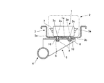
- FIG. 1 is an exploded perspective view showing a preferred embodiment of a passenger seat airbag structure according to the present invention.
- FIG. FIG. 2 is a partial cross-sectional side view showing an assembled state of the passenger seat airbag structure shown in FIG. 1.
- the airbag structure for a passenger seat mainly includes an inflator 1, an airbag cushion 2 that is deployed and inflated by an inflator gas ejected from the inflator 1, and an airbag cushion. And a housing 3 for housing 2.
- the vehicle body side support member is integrally joined to the cross beam 4 disposed in the width direction of the vehicle body, and the mount 5 to which the inflator 1 and the housing 3 are attached. It consists of. *
- the inflator 1 is a metal pressure-resistant container and is filled with explosives.
- the outer shape of the inflator 1 is formed in a disk shape having an appropriate thickness.
- the bottom surface 1a of the inflator 1 is formed as a circular flat surface as a fixing mounting surface.
- a plurality of mounting bolts 6 are integrally provided on the bottom surface 1 a of the inflator 1. One end of the mounting bolt 6 is joined to the bottom surface 1 a of the inflator 1 and protrudes downward from the bottom surface 1 a of the inflator 1. *
- a ring-shaped rectifying plate 7 is provided on the outer peripheral side surface of the inflator 1 so as to surround it.
- the rectifying plate 7 rectifies the inflator gas ejected from the gas ejection holes of the inflator 1.
- the airbag cushion 2 is made of fabric, has a conventionally known structure, and is folded when the vehicle body is mounted. The entire inflator 1 is accommodated inside the airbag cushion 2.
- the airbag cushion 2 is formed with a plurality of first through holes 2a through which the mounting bolts 6 of the inflator 1 protrude outward from the airbag cushion 1.
- the mounting bolt 6 is exposed from the airbag cushion 2 with the bottom surface 1 a in contact with the inner surface of the airbag cushion 2.
- the housing 3 is made of metal, and a planar outer contour is formed in a rectangular shape from an annular frame 3a that forms side surfaces and a bottom plate 3b that spans between the annular frames 3a and forms a bottom surface.
- the bottom plate 3b is formed as a flat surface on both the front and back surfaces.
- a mounting bracket 8 extending to the side of the housing 3 is joined to the annular frame 3a.
- the housing 3 defines an internal space whose upper side is opened by the annular frame 3a and the bottom plate 3b.
- the housing may be made of fabric. *
- an airbag cushion 2 containing the inflator 1 is accommodated in the internal space of the housing 3.
- a plurality of second through holes 3 c are formed in the bottom plate 3 b of the housing 3 and penetrate the mounting bolts 6 of the inflator 1 protruding from the first through holes 2 a of the airbag cushion 2.
- the bottom surface 1 a of the inflator 1 is in contact with the top surface of the bottom plate 3 b via the airbag cushion 2, and the mounting bolt 6 is exposed from the housing 3.
- the mount 5 is formed with a flat upward installation surface 5a facing the flat bottom plate 3b.
- Bolt insertion holes 9 are formed on the upward installation surface 5a in accordance with the number of mounting bolts 6. Since the flat upward installation surface 5a of the mount 5 and the flat bottom plate 3b come into contact with each other, the bolt insertion hole 9 that absorbs the assembly tolerance is set to a small loose hole. *
- a mounting bolt 6 that passes through the second through hole 3c of the bottom plate 3b passes.
- the mounting bolt 6 is joined to the mount 5 by fastening the nut 10 from below the upward installation surface 5a.
- the operation of the passenger seat airbag structure according to the present embodiment will be described.
- the assembly procedure will be described. First, the disk-shaped inflator 1 integrally provided with the mounting bolts 6 is accommodated in the airbag cushion 2. Next, the mounting bolt 6 is exposed to the outside through the first through hole 2 a of the airbag cushion 2. *
- the airbag cushion 2 is accommodated in the housing 3 together with the inflator 1.
- the mounting bolt 6 is projected from the bottom plate 3 b through the second through hole 3 c of the housing 3.
- the temporarily fixing washer 11 is attached to the mounting bolt 6 to temporarily fix the inflator 1, the airbag cushion 2 and the housing 3. In this way, the attachment work to the mount 5 can be simplified.
- the flat bottom plate 3 b of the housing 3 is placed on the flat upward installation surface 5 a of the mount 5, and the mounting bolt 6 is passed through the bolt insertion hole 9. Thereafter, the nut 10 is fastened to the mounting bolt 6, and the mount 5 of the cross beam 4 and the mounting bolt 6 of the inflator 1 are joined.
- the inflator 1 is supported and fixed to the mount 5 of the cross beam 4 together with the airbag cushion 2 and the housing 3 by using the bottom surface 1a of the inflator 1 as a fixing mounting surface.
- the impact force due to the rapid combustion action of the inflator 1 acts directly on the mount 5 directly below the inflator bottom surface 1 a from the inflator 1, and the mount 5 receives the impact force together with the cross beam 4.
- the bottom surface 1a of the inflator 1 is a flat fixing mounting surface, and the mounting bolt 6 is integrally provided on the bottom surface 1a. In the state where 1 is entirely housed in the airbag cushion 2, the mounting bolt 6 is used to join the mount 5.
- the inflator is supported on the vehicle body side support member by using a retainer with a bolt without setting a fixing mounting surface. Therefore, the inflator protrudes from the storage case, and the bracket is used to attach the inflator and the storage case to the vehicle body side support member.
- a fixing mounting surface (bottom surface 1a) is set on the inflator 1, and the inflator 1 is accommodated in the airbag cushion 2 and incorporated in the housing 3, so that the inflator 1 protrudes to the outside of the housing 3. Without being exposed, the periphery of the attachment site of the inflator 1 to the mount 5 can be a flat surface.
- the bottom plate 3b of the flat housing 3 is directly mounted on the mount 5, and the inflator 1, the airbag cushion 2 and the housing 3 are joined to the mount 5 by the mounting bolts 6, and the bottom surface 1a of the inflator 1 is mounted directly below the mount 5. Since it can be supported and fixed by 5, the retainer and bracket with a bolt can be abolished.
- the structure in which the inflator 1 is directly joined to the mount 5 with the mounting bolt 6 can support and fix the inflator 1 immediately above the mount 5, and can transmit the impact force of the inflator 1 to the mount 5 efficiently and accurately.
- the support performance of the inflator 1 can be improved.
- the passenger airbag structure described above is a preferred example of the present invention, and other embodiments can be implemented or performed by various methods.
- the present invention is not limited to the detailed shape, size, configuration, and the like of the components shown in the accompanying drawings unless otherwise stated in the present specification.
- expressions and terms used in the present specification are for the purpose of explanation, and are not limited thereto unless otherwise specified.
Landscapes
- Engineering & Computer Science (AREA)
- Mechanical Engineering (AREA)
- Air Bags (AREA)
Abstract
【課題】従来必須であったボルト付きのリテーナやブラケットを廃止することが可能で、部品点数及び組立工数を削減でき、省資源化やエコロジーにも資する助手席用エアバッグ構造を提供する。【解決手段】底面1aを固定用取付面として、当該底面に取付用ボルト6を一体的に設けたディスク形状のインフレータ1と、取付用ボルトが外部へ突出する第1貫通孔2aを有し、内部にインフレータ全体を収容するエアバッグクッション2と、第1貫通孔から突出する取付用ボルトが貫通する第2貫通孔3cを有し、内方にエアバッグクッションを収容するハウジング3と、第2貫通孔を貫通した取付用ボルトと接合され、ハウジングと共にインフレータの底面を支持して固定するマウント5及びクロスビーム4とを備えた。
Description
本発明は、従来必須であったボルト付きのリテーナやブラケットを廃止することが可能で、部品点数及び組立工数を削減でき、省資源化やエコロジーにも資する助手席用エアバッグ構造に関する。
助手席エアバッグとして、例えば特許文献1が知られている。特許文献1の「エアバッグ装置」は、エアバッグ本体とインフレータとを有するエアバッグモジュールを、取付具を介してリインフォースメントに取り付けたエアバッグ装置であって、前記取付具は、前記エアバッグモジュールの収容ケースと、前記エアバッグモジュール及び前記収容ケースを支持して固定する脚部を有したブラケットと、前記収容ケースの底部から突出した突出部材とを備えている。また、前記ブラケットの前記脚部は傾斜部を有し、前記突出部材は、前記収容ケースが衝撃を受けて前記ブラケットを変形させるときに、前記脚部の前記傾斜部を押圧して前記ブラケットの変形を補助するように構成されている。
特許文献1では、インフレータは取付用のフランジを有している。フランジは、エアバッグ本体内部に収納されるリテーナのボルトを利用して、当該リテーナ、エアバッグ本体、エアバッグ本体を収容する収容ケース、並びにブラケットに、ナットで結合される。車体側支持部材であるリインフォースメントに固定部を設け、この固定部にブラケットを取付固定する。
インフレータは、リテーナに取り囲まれる一部分がエアバッグ本体内部に収容されると共に、下半球部が、エアバッグ本体及び収容ケースから突出して、それらの外部に露出される。
特許文献1では、インフレータや、インフレータ周りの収容ケース及びエアバッグ本体を、リインフォースメントの固定部に取り付けるために、ブラケットやボルト付きのリテーナが必要な構造であった。
インフレータは、火薬の急速な燃焼によりインフレータガスを発生する。インフレータは、急速燃焼作用で衝撃を発生する。従って、インフレータは、リインフォースメントに強固に支持固定する必要がある。インフレータをリインフォースメントで強固に支持固定するため、インフレータのフランジに通したリテーナのボルトで、リインフォースメント側との結合を確保していた。このため、ボルト付きのリテーナが必須であった。
収容ケースからインフレータの下半球部が露出するため、フランジに通したリテーナのボルトが収容ケースから突出する部位周辺に、平坦な面が得られない。このため、リテーナのボルトをリインフォースメントの固定部に直接取り付けるには、公差を吸収し得る融通を確保するために、固定部に大きなルーズホールのボルト孔を形成しなければならない。大きな孔径のボルト孔を形成しなければならない結果、固定部の形状が複雑化したり、リテーナの固定部への取り付けが煩雑化してしまう。このような事態を解消するために、リテーナのボルトと固定部との間に、ルーズホールのボルト孔を有するブラケットを追加して設ける必要があった。
さらに、エアバッグ本体及び収容ケースから突出して露出するインフレータの下半球部が、固定部と位置的に干渉することを避ける必要性からも、ブラケットを追加して設けなければならなかった。
本発明は上記従来の課題に鑑みて創案されたものであって、従来必須であったボルト付きのリテーナやブラケットを廃止することが可能で、部品点数及び組立工数を削減でき、省資源化やエコロジーにも資する助手席用エアバッグ構造を提供することを目的とする。
本発明にかかる助手席用エアバッグ構造は、底面を固定用取付面として、当該底面に取付用ボルトを一体的に設けたディスク形状のインフレータと、該取付用ボルトが外部へ突出する第1貫通孔を有し、内部に該インフレータ全体を収容するエアバッグクッションと、該第1貫通孔から突出する該取付用ボルトが貫通する第2貫通孔を有し、内方に該エアバッグクッションを収容するハウジングと、該第2貫通孔を貫通した該取付用ボルトと接合され、該ハウジングと共に該インフレータの底面を支持して固定する車両側支持部材とを備えたことを特徴とする。
該ハウジングは平坦な底部プレートを備えることが好ましい。
該車両側支持部材は、平坦な上向き設置面を備えることが望ましい。
本発明にかかる助手席用エアバッグ構造にあっては、従来必須であったボルト付きのリテーナやブラケットを廃止することができ、部品点数及び組立工数を削減できて、省資源化やエコロジーも資することができる。
以下に、本発明にかかる助手席用エアバッグ構造の好適な一実施形態を、添付図面を参照して詳細に説明する。図1及び図2に示すように、本実施形態に係る助手席用エアバッグ構造は主に、インフレータ1と、インフレータ1から噴出されるインフレータガスで展開膨張するエアバッグクッション2と、エアバッグクッション2を収容するハウジング3とから構成される。
車体側支持部材は、従来周知のように、車体の幅方向に配設されるクロスビーム4と、このクロスビーム4に一体的に接合して設けられ、インフレータ1やハウジング3が取り付けられるマウント5とから構成される。
インフレータ1は、金属製の耐圧容器であって、内部に火薬が充填されている。インフレータ1の外形形態は、適宜厚さを有するディスク形状に形成される。インフレータ1の底面1aは、固定用取付面として、円形状の平坦面で形成される。インフレータ1の底面1aには、複数本の取付用ボルト6が一体的に設けられる。取付用ボルト6は、一端がインフレータ1の底面1aに接合され、インフレータ1の底面1aから下方へ向かって突出される。
インフレータ1の外周側面には、これを取り囲んで、リング状の整流板7が設けられる。整流板7は、インフレータ1のガス噴出孔から噴出されるインフレータガスを整流する。
エアバッグクッション2はファブリック製であって、従来周知の構造を備え、車体搭載時、折り畳まれている。インフレータ1は、その全体がエアバッグクッション2の内部に収容される。エアバッグクッション2には、インフレータ1の取付用ボルト6をエアバッグクッション1外方へ突出させる第1貫通孔2aが複数形成される。
従って、インフレータ1は、底面1aがエアバッグクッション2の内面に接した状態で、取付用ボルト6がエアバッグクッション2から露出される。
ハウジング3は金属製であって、側面を形成する環状フレーム3aと、環状フレーム3a間に掛け渡されて底面を形成する底部プレート3bとから、平面外形輪郭が長方形状に形成される。底部プレート3bは、表裏面とも平坦面で形成される。環状フレーム3aには、ハウジング3側方へ延出される取付ブラケット8が接合される。ハウジング3は、環状フレーム3a及び底部プレート3bによって、上方が開放された内部空間を区画形成する。ハウジングは、ファブリック製であってもよい。
ハウジング3の内部空間には、インフレータ1を内蔵したエアバッグクッション2が収容される。ハウジング3の底部プレート3bには、エアバッグクッション2の第1貫通孔2aから突出するインフレータ1の取付用ボルト6を貫通させる第2貫通孔3cが複数形成される。
従って、インフレータ1の底面1aは、エアバッグクッション2を介して、底部プレート3b上面に接し、また、取付用ボルト6がハウジング3から露出される。
マウント5には、平坦な底部プレート3bに面して、平坦な上向き設置面5aが形成される。上向き設置面5aには、取付用ボルト6の本数に応じて、ボルト挿通孔9が形成される。マウント5の平坦な上向き設置面5aと平坦な底部プレート3bとが当接するので、組み付け公差を吸収するボルト挿通孔9は、小さなルーズホールに設定される。
ボルト挿通孔9には、底部プレート3bの第2貫通孔3cを貫通した取付用ボルト6が貫通する。取付用ボルト6は、上向き設置面5a下方からナット10を締結することで、マウント5と接合される。
次に、本実施形態に係る助手席用エアバッグ構造の作用について説明する。組み付け手順について説明すると、まず、取付用ボルト6を一体的に設けたディスク形状のインフレータ1を、エアバッグクッション2内部に収容する。次に、取付用ボルト6を、エアバッグクッション2の第1貫通孔2aを通して、外部に露出する。
次に、インフレータ1と共に、エアバッグクッション2をハウジング3内部に収容する。次に、取付用ボルト6を、ハウジング3の第2貫通孔3cを通して、底部プレート3bから突出させる。この際、取付用ボルト6に仮止めワッシャ11を装着し、インフレータ1、エアバッグクッション2及びハウジング3を仮止めする。このようにすれば、マウント5への取付作業を簡便化することができる。
次に、ハウジング3の平坦な底部プレート3bを、マウント5の平坦な上向き設置面5a上に載せると共に、取付用ボルト6をボルト挿通孔9へ通す。その後、ナット10を取付用ボルト6に締結して、クロスビーム4のマウント5とインフレータ1の取付用ボルト6とを接合する。このように組み付けることで、インフレータ1の底面1aを固定用取付面として、エアバッグクッション2及びハウジング3と共に、インフレータ1がクロスビーム4のマウント5に支持されて固定される。
インフレータ1の作動時は、インフレータ1の急速燃焼作用による衝撃力は、当該インフレータ1から直接、インフレータ底面1a直下のマウント5に作用し、当該マウント5が、クロスビーム4と共に、衝撃力を受け止める。
以上説明した本実施形態に係る助手席用エアバッグ構造にあっては、インフレータ1の底面1aを平坦な固定用取付面とし、この底面1aに取付用ボルト6を一体的に設けると共に、このインフレータ1全体をエアバッグクッション2内部に収容した状態で、取付用ボルト6でマウント5に接合するようにしている。
背景技術では、インフレータに固定用取付面を設定することなく、ボルト付きリテーナを利用して車体側支持部材に支持するようにしていた。従って、インフレータは、収容ケースから突出し、これらインフレータ及び収容ケースの車体側支持部材への取り付けにブラケットを利用していた。
本実施形態では、インフレータ1に固定用取付面(底面1a)を設定し、当該インフレータ1をエアバッグクッション2に収容してハウジング3に内蔵しているので、インフレータ1がハウジング3外部へ突出したり露出することがなく、インフレータ1のマウント5への取り付け部位周辺を平坦面とすることができる。
そして平坦なハウジング3の底部プレート3bを直接マウント5へ載せ、取付用ボルト6により、インフレータ1、エアバッグクッション2及びハウジング3をマウント5に接合して、インフレータ1の底面1aを、直下のマウント5で支持固定することができるので、ボルト付きのリテーナやブラケットを廃止することができる。
これらリテーナやブラケットの廃止により、部品点数や組立工数を削減することができると共に、これにより、省資源化やエコロジーに資することができる。
インフレータ1を取付用ボルト6でマウント5に直接接合する構造は、マウント5直上でインフ
レータ1を支持して固定することができ、インフレータ1の衝撃力を効率良く的確にマウント5に伝達することができて、インフレータ1の支持性能を向上することができる。
レータ1を支持して固定することができ、インフレータ1の衝撃力を効率良く的確にマウント5に伝達することができて、インフレータ1の支持性能を向上することができる。
インフレータ1の取付位置でハウジング3をマウント5上に支持する構造であり、インフレータ1の衝撃力をマウント5で直接受け止めることができるので、インフレータ1の取付位置におけるハウジング3の変形を抑制することができる。
平坦な底部プレート3bを、マウント5の平坦な上向き設置面5aへ組み付けるので、組み付け公差を吸収するボルト挿通孔9は小さなルーズホールで十分であり、マウント5の形状が複雑化することを防止でき、公差を吸収する目的のブラケットを廃止することができる。
以上に述べた助手席用エアバッグ構造は、本発明の好ましい例であって、これ以外の実施形態例も、各種の方法で実施または遂行できる。特に、本願明細書中に限定される主旨の記載がない限り、この発明は、添付図面に示した詳細な部品の形状、大きさおよび構成配置等に制約されるものではない。また、本願明細書中に用いられた表現および用語は、説明を目的としたもので、特に限定される主旨の記載がない限り、それに限定されるものではない。
1 ディスク形状のインフレータ 1a インフレータの底面 2 エアバッグクッション 2a 第1貫通孔 3 ハウジング 3b 底部プレート 3c 第2貫通孔 4 クロスビーム 5 マウント 5a 上向き設置面 6 取付用ボルト
Claims (3)
- 底面を固定用取付面として、当該底面に取付用ボルトを一体的に設けたディスク形状のインフレータと、該取付用ボルトが外部へ突出する第1貫通孔を有し、内部に該インフレータ全体を収容するエアバッグクッションと、該第1貫通孔から突出する該取付用ボルトが貫通する第2貫通孔を有し、内方に該エアバッグクッションを収容するハウジングと、該第2貫通孔を貫通した該取付用ボルトと接合され、該ハウジングと共に該インフレータの底面を支持して固定する車両側支持部材とを備えたことを特徴とする助手席用エアバッグ構造。
- 該ハウジングは平坦な底部プレートを備えることを特徴とする請求項1記載の助手席用エアバッグ構造。
- 該車両側支持部材は、平坦な上向き設置面を備えることを特徴とする請求項1または2に記載の助手席用エアバッグ構造。
Priority Applications (1)
| Application Number | Priority Date | Filing Date | Title |
|---|---|---|---|
| CN201080056522.3A CN102666212B (zh) | 2009-12-18 | 2010-12-08 | 副驾驶席用安全气囊结构 |
Applications Claiming Priority (2)
| Application Number | Priority Date | Filing Date | Title |
|---|---|---|---|
| JP2009-287210 | 2009-12-18 | ||
| JP2009287210A JP2012236427A (ja) | 2009-12-18 | 2009-12-18 | 助手席用エアバッグ構造 |
Publications (1)
| Publication Number | Publication Date |
|---|---|
| WO2011074451A1 true WO2011074451A1 (ja) | 2011-06-23 |
Family
ID=44167208
Family Applications (1)
| Application Number | Title | Priority Date | Filing Date |
|---|---|---|---|
| PCT/JP2010/071979 Ceased WO2011074451A1 (ja) | 2009-12-18 | 2010-12-08 | 助手席用エアバッグ構造 |
Country Status (3)
| Country | Link |
|---|---|
| JP (1) | JP2012236427A (ja) |
| CN (1) | CN102666212B (ja) |
| WO (1) | WO2011074451A1 (ja) |
Cited By (1)
| Publication number | Priority date | Publication date | Assignee | Title |
|---|---|---|---|---|
| JP2013173449A (ja) * | 2012-02-24 | 2013-09-05 | Ashimori Industry Co Ltd | エアバッグ装置 |
Citations (3)
| Publication number | Priority date | Publication date | Assignee | Title |
|---|---|---|---|---|
| JPH068118U (ja) * | 1992-07-08 | 1994-02-01 | 日本精工株式会社 | エアバッグ装置 |
| JP2001277979A (ja) * | 2000-03-29 | 2001-10-10 | Toyoda Gosei Co Ltd | エアバッグ装置 |
| JP2002225664A (ja) * | 2001-01-29 | 2002-08-14 | Toyo Tire & Rubber Co Ltd | エアバッグ装置 |
Family Cites Families (5)
| Publication number | Priority date | Publication date | Assignee | Title |
|---|---|---|---|---|
| GB2268124B (en) * | 1992-06-02 | 1995-07-12 | Autoliv Dev | Improvements in or relating to an air-bag arrangement |
| DE19538594C2 (de) * | 1995-10-17 | 1997-08-14 | Autoliv Dev | Airbag-Anordnung |
| US7255364B2 (en) * | 2004-03-05 | 2007-08-14 | Key Safety Systems, Inc. | Driver air bag cover and attachment method |
| CN100488814C (zh) * | 2004-08-04 | 2009-05-20 | 高田株式会社 | 乘员保护装置 |
| JP2008110737A (ja) * | 2006-10-31 | 2008-05-15 | Nippon Plast Co Ltd | エアバッグ装置 |
-
2009
- 2009-12-18 JP JP2009287210A patent/JP2012236427A/ja not_active Withdrawn
-
2010
- 2010-12-08 CN CN201080056522.3A patent/CN102666212B/zh not_active Expired - Fee Related
- 2010-12-08 WO PCT/JP2010/071979 patent/WO2011074451A1/ja not_active Ceased
Patent Citations (3)
| Publication number | Priority date | Publication date | Assignee | Title |
|---|---|---|---|---|
| JPH068118U (ja) * | 1992-07-08 | 1994-02-01 | 日本精工株式会社 | エアバッグ装置 |
| JP2001277979A (ja) * | 2000-03-29 | 2001-10-10 | Toyoda Gosei Co Ltd | エアバッグ装置 |
| JP2002225664A (ja) * | 2001-01-29 | 2002-08-14 | Toyo Tire & Rubber Co Ltd | エアバッグ装置 |
Cited By (1)
| Publication number | Priority date | Publication date | Assignee | Title |
|---|---|---|---|---|
| JP2013173449A (ja) * | 2012-02-24 | 2013-09-05 | Ashimori Industry Co Ltd | エアバッグ装置 |
Also Published As
| Publication number | Publication date |
|---|---|
| CN102666212B (zh) | 2015-05-06 |
| JP2012236427A (ja) | 2012-12-06 |
| CN102666212A (zh) | 2012-09-12 |
Similar Documents
| Publication | Publication Date | Title |
|---|---|---|
| JP7121315B2 (ja) | サイドエアバッグ装置 | |
| CN102256834B (zh) | 方向盘装置 | |
| JP4473902B2 (ja) | 防振部材の取付構造 | |
| JP2007112433A (ja) | 運転席用エアバッグモジュールの結合構造 | |
| JP2014054991A (ja) | エアバッグモジュールを備えたステアリングホイール構造 | |
| JP6085453B2 (ja) | エアバッグ装置 | |
| CN105431335B (zh) | 充气机的安装结构及气囊装置 | |
| JP2009173197A (ja) | クリップ座の取付構造及びドアトリムの取付構造 | |
| JP2016168910A (ja) | バッテリー取付構造 | |
| WO2011074451A1 (ja) | 助手席用エアバッグ構造 | |
| JPH10278647A (ja) | 車両用シートにおけるシートバックの取付構造 | |
| JP2012056460A (ja) | エアバッグモジュールを備えたステアリングホイール構造 | |
| WO2020213382A1 (ja) | サイドエアバッグ装置 | |
| JP2011126430A (ja) | 車両用エアバッグ構造 | |
| JP2006097741A (ja) | エンジンマウント | |
| JP2008002565A (ja) | 防振装置 | |
| JP2011025916A (ja) | 車両用エアバッグのインフレータ構造、エアバッグモジュールおよびエアバッグ構造 | |
| JP4004498B2 (ja) | 車両用エアバッグの取り付け構造 | |
| JP2011136607A (ja) | 車両用エアバッグのインフレータ構造 | |
| CN218121336U (zh) | 用于碰撞试验的吸能装置和具有其的碰撞试验设备 | |
| CN208360122U (zh) | 后雨刮快速安装结构 | |
| CN215360822U (zh) | 螺旋弹簧安装垫及车辆 | |
| WO2010150869A1 (ja) | 車両用エアバッグのインフレータ構造、エアバッグモジュールおよびエアバッグ構造 | |
| JP4599605B2 (ja) | 自動車用シートの取付け構造 | |
| JP2020050208A (ja) | サブフレーム構造 |
Legal Events
| Date | Code | Title | Description |
|---|---|---|---|
| WWE | Wipo information: entry into national phase |
Ref document number: 201080056522.3 Country of ref document: CN |
|
| 121 | Ep: the epo has been informed by wipo that ep was designated in this application |
Ref document number: 10837480 Country of ref document: EP Kind code of ref document: A1 |
|
| NENP | Non-entry into the national phase |
Ref country code: DE |
|
| NENP | Non-entry into the national phase |
Ref country code: JP |
|
| 122 | Ep: pct application non-entry in european phase |
Ref document number: 10837480 Country of ref document: EP Kind code of ref document: A1 |