WO2011074192A1 - 酸素濃縮装置 - Google Patents
酸素濃縮装置 Download PDFInfo
- Publication number
- WO2011074192A1 WO2011074192A1 PCT/JP2010/006946 JP2010006946W WO2011074192A1 WO 2011074192 A1 WO2011074192 A1 WO 2011074192A1 JP 2010006946 W JP2010006946 W JP 2010006946W WO 2011074192 A1 WO2011074192 A1 WO 2011074192A1
- Authority
- WO
- WIPO (PCT)
- Prior art keywords
- compressor
- oxygen
- air
- pipe
- compressed air
- Prior art date
- Legal status (The legal status is an assumption and is not a legal conclusion. Google has not performed a legal analysis and makes no representation as to the accuracy of the status listed.)
- Ceased
Links
Images



Classifications
-
- A—HUMAN NECESSITIES
- A61—MEDICAL OR VETERINARY SCIENCE; HYGIENE
- A61M—DEVICES FOR INTRODUCING MEDIA INTO, OR ONTO, THE BODY; DEVICES FOR TRANSDUCING BODY MEDIA OR FOR TAKING MEDIA FROM THE BODY; DEVICES FOR PRODUCING OR ENDING SLEEP OR STUPOR
- A61M16/00—Devices for influencing the respiratory system of patients by gas treatment, e.g. ventilators; Tracheal tubes
- A61M16/10—Preparation of respiratory gases or vapours
-
- A—HUMAN NECESSITIES
- A61—MEDICAL OR VETERINARY SCIENCE; HYGIENE
- A61M—DEVICES FOR INTRODUCING MEDIA INTO, OR ONTO, THE BODY; DEVICES FOR TRANSDUCING BODY MEDIA OR FOR TAKING MEDIA FROM THE BODY; DEVICES FOR PRODUCING OR ENDING SLEEP OR STUPOR
- A61M16/00—Devices for influencing the respiratory system of patients by gas treatment, e.g. ventilators; Tracheal tubes
- A61M16/06—Respiratory or anaesthetic masks
- A61M16/0666—Nasal cannulas or tubing
- A61M16/0672—Nasal cannula assemblies for oxygen therapy
-
- A—HUMAN NECESSITIES
- A61—MEDICAL OR VETERINARY SCIENCE; HYGIENE
- A61M—DEVICES FOR INTRODUCING MEDIA INTO, OR ONTO, THE BODY; DEVICES FOR TRANSDUCING BODY MEDIA OR FOR TAKING MEDIA FROM THE BODY; DEVICES FOR PRODUCING OR ENDING SLEEP OR STUPOR
- A61M16/00—Devices for influencing the respiratory system of patients by gas treatment, e.g. ventilators; Tracheal tubes
- A61M16/10—Preparation of respiratory gases or vapours
- A61M16/1005—Preparation of respiratory gases or vapours with O2 features or with parameter measurement
- A61M16/101—Preparation of respiratory gases or vapours with O2 features or with parameter measurement using an oxygen concentrator
-
- A—HUMAN NECESSITIES
- A61—MEDICAL OR VETERINARY SCIENCE; HYGIENE
- A61M—DEVICES FOR INTRODUCING MEDIA INTO, OR ONTO, THE BODY; DEVICES FOR TRANSDUCING BODY MEDIA OR FOR TAKING MEDIA FROM THE BODY; DEVICES FOR PRODUCING OR ENDING SLEEP OR STUPOR
- A61M16/00—Devices for influencing the respiratory system of patients by gas treatment, e.g. ventilators; Tracheal tubes
- A61M16/20—Valves specially adapted to medical respiratory devices
- A61M16/201—Controlled valves
- A61M16/202—Controlled valves electrically actuated
- A61M16/203—Proportional
-
- B—PERFORMING OPERATIONS; TRANSPORTING
- B01—PHYSICAL OR CHEMICAL PROCESSES OR APPARATUS IN GENERAL
- B01D—SEPARATION
- B01D53/00—Separation of gases or vapours; Recovering vapours of volatile solvents from gases; Chemical or biological purification of waste gases, e.g. engine exhaust gases, smoke, fumes, flue gases, aerosols
- B01D53/02—Separation of gases or vapours; Recovering vapours of volatile solvents from gases; Chemical or biological purification of waste gases, e.g. engine exhaust gases, smoke, fumes, flue gases, aerosols by adsorption, e.g. preparative gas chromatography
- B01D53/04—Separation of gases or vapours; Recovering vapours of volatile solvents from gases; Chemical or biological purification of waste gases, e.g. engine exhaust gases, smoke, fumes, flue gases, aerosols by adsorption, e.g. preparative gas chromatography with stationary adsorbents
- B01D53/0407—Constructional details of adsorbing systems
- B01D53/0446—Means for feeding or distributing gases
-
- A—HUMAN NECESSITIES
- A61—MEDICAL OR VETERINARY SCIENCE; HYGIENE
- A61M—DEVICES FOR INTRODUCING MEDIA INTO, OR ONTO, THE BODY; DEVICES FOR TRANSDUCING BODY MEDIA OR FOR TAKING MEDIA FROM THE BODY; DEVICES FOR PRODUCING OR ENDING SLEEP OR STUPOR
- A61M16/00—Devices for influencing the respiratory system of patients by gas treatment, e.g. ventilators; Tracheal tubes
- A61M16/10—Preparation of respiratory gases or vapours
- A61M16/105—Filters
- A61M16/106—Filters in a path
- A61M16/107—Filters in a path in the inspiratory path
-
- A—HUMAN NECESSITIES
- A61—MEDICAL OR VETERINARY SCIENCE; HYGIENE
- A61M—DEVICES FOR INTRODUCING MEDIA INTO, OR ONTO, THE BODY; DEVICES FOR TRANSDUCING BODY MEDIA OR FOR TAKING MEDIA FROM THE BODY; DEVICES FOR PRODUCING OR ENDING SLEEP OR STUPOR
- A61M16/00—Devices for influencing the respiratory system of patients by gas treatment, e.g. ventilators; Tracheal tubes
- A61M16/10—Preparation of respiratory gases or vapours
- A61M16/14—Preparation of respiratory gases or vapours by mixing different fluids, one of them being in a liquid phase
- A61M16/16—Devices to humidify the respiration air
-
- A—HUMAN NECESSITIES
- A61—MEDICAL OR VETERINARY SCIENCE; HYGIENE
- A61M—DEVICES FOR INTRODUCING MEDIA INTO, OR ONTO, THE BODY; DEVICES FOR TRANSDUCING BODY MEDIA OR FOR TAKING MEDIA FROM THE BODY; DEVICES FOR PRODUCING OR ENDING SLEEP OR STUPOR
- A61M16/00—Devices for influencing the respiratory system of patients by gas treatment, e.g. ventilators; Tracheal tubes
- A61M16/0003—Accessories therefor, e.g. sensors, vibrators, negative pressure
- A61M2016/003—Accessories therefor, e.g. sensors, vibrators, negative pressure with a flowmeter
- A61M2016/0033—Accessories therefor, e.g. sensors, vibrators, negative pressure with a flowmeter electrical
- A61M2016/0039—Accessories therefor, e.g. sensors, vibrators, negative pressure with a flowmeter electrical in the inspiratory circuit
-
- A—HUMAN NECESSITIES
- A61—MEDICAL OR VETERINARY SCIENCE; HYGIENE
- A61M—DEVICES FOR INTRODUCING MEDIA INTO, OR ONTO, THE BODY; DEVICES FOR TRANSDUCING BODY MEDIA OR FOR TAKING MEDIA FROM THE BODY; DEVICES FOR PRODUCING OR ENDING SLEEP OR STUPOR
- A61M16/00—Devices for influencing the respiratory system of patients by gas treatment, e.g. ventilators; Tracheal tubes
- A61M16/10—Preparation of respiratory gases or vapours
- A61M16/1005—Preparation of respiratory gases or vapours with O2 features or with parameter measurement
- A61M2016/102—Measuring a parameter of the content of the delivered gas
- A61M2016/1025—Measuring a parameter of the content of the delivered gas the O2 concentration
-
- A—HUMAN NECESSITIES
- A61—MEDICAL OR VETERINARY SCIENCE; HYGIENE
- A61M—DEVICES FOR INTRODUCING MEDIA INTO, OR ONTO, THE BODY; DEVICES FOR TRANSDUCING BODY MEDIA OR FOR TAKING MEDIA FROM THE BODY; DEVICES FOR PRODUCING OR ENDING SLEEP OR STUPOR
- A61M2205/00—General characteristics of the apparatus
- A61M2205/42—Reducing noise
-
- A—HUMAN NECESSITIES
- A61—MEDICAL OR VETERINARY SCIENCE; HYGIENE
- A61M—DEVICES FOR INTRODUCING MEDIA INTO, OR ONTO, THE BODY; DEVICES FOR TRANSDUCING BODY MEDIA OR FOR TAKING MEDIA FROM THE BODY; DEVICES FOR PRODUCING OR ENDING SLEEP OR STUPOR
- A61M2205/00—General characteristics of the apparatus
- A61M2205/50—General characteristics of the apparatus with microprocessors or computers
- A61M2205/502—User interfaces, e.g. screens or keyboards
-
- A—HUMAN NECESSITIES
- A61—MEDICAL OR VETERINARY SCIENCE; HYGIENE
- A61M—DEVICES FOR INTRODUCING MEDIA INTO, OR ONTO, THE BODY; DEVICES FOR TRANSDUCING BODY MEDIA OR FOR TAKING MEDIA FROM THE BODY; DEVICES FOR PRODUCING OR ENDING SLEEP OR STUPOR
- A61M2205/00—General characteristics of the apparatus
- A61M2205/82—Internal energy supply devices
- A61M2205/8206—Internal energy supply devices battery-operated
-
- B—PERFORMING OPERATIONS; TRANSPORTING
- B01—PHYSICAL OR CHEMICAL PROCESSES OR APPARATUS IN GENERAL
- B01D—SEPARATION
- B01D2253/00—Adsorbents used in seperation treatment of gases and vapours
- B01D2253/10—Inorganic adsorbents
- B01D2253/106—Silica or silicates
- B01D2253/108—Zeolites
-
- B—PERFORMING OPERATIONS; TRANSPORTING
- B01—PHYSICAL OR CHEMICAL PROCESSES OR APPARATUS IN GENERAL
- B01D—SEPARATION
- B01D2256/00—Main component in the product gas stream after treatment
- B01D2256/12—Oxygen
-
- B—PERFORMING OPERATIONS; TRANSPORTING
- B01—PHYSICAL OR CHEMICAL PROCESSES OR APPARATUS IN GENERAL
- B01D—SEPARATION
- B01D2257/00—Components to be removed
- B01D2257/10—Single element gases other than halogens
- B01D2257/102—Nitrogen
-
- B—PERFORMING OPERATIONS; TRANSPORTING
- B01—PHYSICAL OR CHEMICAL PROCESSES OR APPARATUS IN GENERAL
- B01D—SEPARATION
- B01D2259/00—Type of treatment
- B01D2259/12—Methods and means for introducing reactants
- B01D2259/122—Gaseous reactants
-
- B—PERFORMING OPERATIONS; TRANSPORTING
- B01—PHYSICAL OR CHEMICAL PROCESSES OR APPARATUS IN GENERAL
- B01D—SEPARATION
- B01D2259/00—Type of treatment
- B01D2259/40—Further details for adsorption processes and devices
- B01D2259/402—Further details for adsorption processes and devices using two beds
-
- B—PERFORMING OPERATIONS; TRANSPORTING
- B01—PHYSICAL OR CHEMICAL PROCESSES OR APPARATUS IN GENERAL
- B01D—SEPARATION
- B01D2259/00—Type of treatment
- B01D2259/45—Gas separation or purification devices adapted for specific applications
- B01D2259/4533—Gas separation or purification devices adapted for specific applications for medical purposes
-
- B—PERFORMING OPERATIONS; TRANSPORTING
- B01—PHYSICAL OR CHEMICAL PROCESSES OR APPARATUS IN GENERAL
- B01D—SEPARATION
- B01D2259/00—Type of treatment
- B01D2259/45—Gas separation or purification devices adapted for specific applications
- B01D2259/4541—Gas separation or purification devices adapted for specific applications for portable use, e.g. gas masks
-
- B—PERFORMING OPERATIONS; TRANSPORTING
- B01—PHYSICAL OR CHEMICAL PROCESSES OR APPARATUS IN GENERAL
- B01D—SEPARATION
- B01D53/00—Separation of gases or vapours; Recovering vapours of volatile solvents from gases; Chemical or biological purification of waste gases, e.g. engine exhaust gases, smoke, fumes, flue gases, aerosols
- B01D53/02—Separation of gases or vapours; Recovering vapours of volatile solvents from gases; Chemical or biological purification of waste gases, e.g. engine exhaust gases, smoke, fumes, flue gases, aerosols by adsorption, e.g. preparative gas chromatography
- B01D53/04—Separation of gases or vapours; Recovering vapours of volatile solvents from gases; Chemical or biological purification of waste gases, e.g. engine exhaust gases, smoke, fumes, flue gases, aerosols by adsorption, e.g. preparative gas chromatography with stationary adsorbents
- B01D53/047—Pressure swing adsorption
Definitions
- the present invention relates to an oxygen concentrator, and more particularly to a medical oxygen concentrator capable of supplying oxygen by compressing taken raw material air and supplying the compressed air to an adsorbent.
- the oxygen concentrator is configured to obtain oxygen by using a pressure swing adsorption method that generates oxygen by using, as an adsorbent, a zeolite that selectively adsorbs nitrogen by permeating oxygen in the raw material air.
- a pressure swing adsorption method that generates oxygen by using, as an adsorbent, a zeolite that selectively adsorbs nitrogen by permeating oxygen in the raw material air.
- the raw material air taken in is compressed by a compressor to generate compressed air, and this compressed air is supplied to an adsorbing cylinder with a built-in adsorbent, thereby supplying nitrogen to the adsorbent. Is adsorbed to generate oxygen.
- the generated oxygen is stored in a tank, and the patient can inhale oxygen using a device such as a nasal cannula by enabling the supply of a predetermined flow rate of oxygen from the tank via a pressure reducing valve or a flow rate setting device.
- a device such as a nasal cannula by enabling the supply of a predetermined flow rate of oxygen from the tank via a pressure reducing valve or a flow rate setting device.
- this oxygen concentrator is installed in a place where an AC power supply (commercial AC power supply) can be used, for example, a home oxygen therapy patient with reduced lung function will be able to safely take oxygen even while sleeping. it can.
- an AC power supply commercial AC power supply
- the oxygen concentrator when a home oxygen therapy patient is used while sleeping, it is preferable that the oxygen concentrator generates very little noise. For example, it is desirable that the noise of the oxygen concentrator is less than or equal to the noise level generated from indoor air conditioning equipment.
- oxygen concentrators used for long-term oxygen inhalation therapy which is effective as a treatment for patients with respiratory diseases such as chronic bronchitis, are generally not portable, so that patients can take them outside. Not configured.
- concentrated oxygen is sucked from the oxygen cylinder.
- This oxygen cylinder must be filled with oxygen in a dedicated facility. Therefore, portable or mobile oxygen concentrators have been proposed, and portable or mobile oxygen concentrators include a compressor that takes in raw material air and generates compressed air and decompressed air (Patent Document 1). See).
- the present invention provides an oxygen concentrator that can reduce the pressure loss during intake of raw material air and increase the intake amount of raw material air by that amount without significantly changing the basic structure of the compressor. Objective.
- the present invention has a plurality of suction ports for sucking raw material air, compresses the sucked raw material air to generate compressed air, and reduces noise from the suction port in the front stage of the compressor
- a silencer is provided, and a plurality of suction ports from the compressor and the silencer are individually connected. According to the above configuration, it is possible to reduce the amount of raw material air sent per connecting pipe by directly connecting the plurality of raw material air intake ports of the compressor to the silencer using separate connecting pipes. Thus, the raw material air can be taken into the compressor without loss by reducing the pressure loss.
- the compressor has a first pump part and a second pump part that respectively generate the compressed air by compressing the raw material air by reciprocating a piston in a sleeve,
- the first pump and the second pump part are provided with the suction port, respectively.
- the silencer has a filter that removes dust from the compressed air.
- the compressed air can be sent to a plurality of connecting pipes after the filter removes dust from the compressed air, and the amount of raw material air sent per connecting pipe is reduced to reduce the effect of pressure loss. it can.
- the present invention can provide an oxygen concentrator capable of reducing the pressure loss during intake of raw material air and increasing the intake amount of raw material air by that amount without greatly changing the basic structure of the compressor.
- FIG. 1 It is the perspective view seen from the front side which shows the external appearance of embodiment of an oxygen concentrator provided with the compressor of this invention. It is a rear view of the external appearance of the oxygen concentrator of FIG. It is the perspective view seen from the diagonally back side which shows the example of an internal structure of the oxygen concentrator shown in FIG. 1 and FIG. It is a figure which shows the 1st connection piping connected to the compressor, the 2nd connection piping, and the suction filter and muffler buffer. It is a figure which shows the system structural example of an oxygen concentrator. It is a figure which shows the connection of the conventional compressor and piping.
- FIG. 1 is a perspective view seen from the front side showing the appearance of an embodiment of an oxygen concentrator equipped with a compressor of the present invention.
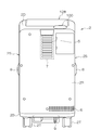
- FIG. 2 is a rear view of the appearance of the oxygen concentrator in FIG.
- the oxygen concentrator 1 shown in FIGS. 1 and 2 is preferably a portable (also referred to as portable or mobile) oxygen concentrator.
- the oxygen concentrator 1 shown in FIG. 1 uses, for example, a compressed air force fluctuation adsorption method (PSA) with compressed air as an oxygen generation principle.
- PSA compressed air force fluctuation adsorption method
- the oxygen concentrator 1 shown in FIGS. 1 and 2 is an oxygen concentrator having a maximum oxygen flow rate of 5 L class as an example, with a height of about 630 mm, a width of about 350 mm, a depth of about 300 mm, and a weight of 21 to 23 kg.
- the unit for setting the oxygen flow rate is set, for example, from 0.25 L to 5.00 L.
- the oxygen concentrator 1 includes a substantially rectangular parallelepiped main housing 2, a display unit 128 capable of setting a flow rate, a humidifier G, a cannula hook 2K, and casters 2T at four corners.
- the main housing 2 has a front panel 2F, left and right side panels 2S, a rear panel 2R, an upper surface portion 2D, and a bottom portion 2B.
- soundproofing materials polyolefin fibers (preferably polypropylene fibers) having a fiber diameter of 1 to 4 ⁇ m and polyolefin fibers (preferably polypropylene fibers) having a fiber diameter of 20 to 30 ⁇ m are preferable.
- Polypropylene fibers can be used.
- a lightweight and soundproofing effect can be obtained using such a nonwoven fabric.
- a display unit 128, an oxygen outlet unit 100, a power switch 101, and an oxygen flow rate setting button 102 are arranged on the upper surface 2D.
- An arrangement portion 2G for the humidifier G is provided on the upper portion of the front panel 2F.
- the casters 2T are arranged at the four corners of the bottom 2B, and the oxygen concentrator 1 is movable using these casters 2.
- an air intake 5 for taking outside air into the main housing 2 is formed at the center of the upper portion, and warm air in the main housing 2 is exposed to the outside on the right side of the lower portion.
- An exhaust port 6 for discharging is formed.
- An air intake filter 7 is detachably mounted on the inner surface side of the air intake 5.
- the left and right side panels 2 ⁇ / b> B have handles 8, and the bottom 2 ⁇ / b> B has a windable power cord 9.
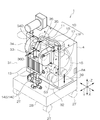
- FIG. 3 is a perspective view showing an example of the internal structure of the oxygen concentrator 1 shown in FIGS. 1 and 2 as seen from an oblique rear side.
- FIG. 4 is a diagram illustrating the horizontally opposed compressor 10, the first connection pipe 40, the second connection pipe 41, and the intake filter / silence buffer 38 connected to the compressor 10.
- the first connection pipe 40 and the second connection pipe 41 are made of a thermoplastic resin, such as polyurethane, to facilitate handling when mounting, and have an inner diameter of 4 to 6 mm, an outer diameter of 7 to 9 mm, and a wall thickness.
- the inner diameter is 5 mm
- the outer diameter is 8 mm
- the wall thickness is 1.5 mm.
- a compressor 10 is set on the bottom 2B, and the compressor 10 is disposed in a soundproof compressor case 4 having a rectangular parallelepiped shape.
- a polyolefin fiber preferably a polypropylene fiber
- a polyolefin fiber having a fiber diameter of 1 to 4 ⁇ m and a polyolefin fiber (preferably a fiber of 20 to 30 ⁇ m) are preferably used.
- Nonwoven fabric made of polypropylene fiber can be used. A lightweight and soundproofing effect can be obtained using such a nonwoven fabric.
- a first adsorption cylinder 31 and a second adsorption cylinder 32 are fixed to the back surface portion of the compressor case 4 with an interval along the X direction and in parallel along the Z direction (vertical direction). Yes.
- the sleeve 12 of the compressor 10 is connected to a pipe 15, and a cooling radiator 13 and three-way switching valves 14 ⁇ / b> B and 14 ⁇ / b> C are connected in the middle of the pipe 15.
- a first fan 34 is attached to the inside of the first adsorption cylinder 31, and a second fan 36 is attached to the inside of the second adsorption cylinder 32.
- the first fan 34 and the second fan 36 having the same shape are, for example, sirocco fans and are located facing each other.
- the mounting direction of the first fan 34 and the second fan 36 is different. These are fixed so as to be upside down with respect to each other and so as to face each other.
- the cooling radiator 13 is disposed between the first adsorption cylinder 31 and the second adsorption cylinder 32 and below the first fan 34 and the second fan 36.
- a power control circuit 39 is disposed on the bottom 2B.
- FIG. 4 is a diagram illustrating a structure example of the compressor 10, and the compressor 10 includes a first pump unit 51 and a second pump unit 52.
- the first pump portion 51 includes a cylindrical sleeve 11, a piston 11P, a head cover 11H, a connecting rod 11C, and a case portion 11F disposed in the sleeve 11.
- the second pump portion 52 includes a cylindrical sleeve 12, a piston 12P, a head cover 12H, a connecting rod 12C, and a case portion 12F disposed in the sleeve 12.
- the sleeves 11 and 12 are also called piston cylinders.
- the drive motor 53 is a synchronous motor, for example, and has an output shaft 54. Connecting rods 11 ⁇ / b> C and 12 ⁇ / b> C are rotatably supported at both ends of the output shaft 54.
- an intake filter / silence buffer (silencer, silencer) 38 is disposed between the pipe 37, the first connection pipe 40, and the second connection pipe 41.
- the first connection pipe 40 and the second connection pipe 41 are made of a thermoplastic resin, such as polyurethane, to facilitate handling when mounting, and have an inner diameter of 4 to 6 mm, an outer diameter of 7 to 9 mm, and a wall thickness.
- the inner diameter is 5 mm
- the outer diameter is 8 mm
- the wall thickness is 1.5 mm. If the outer diameter is larger than 9mm, the bending radius will be larger during handling, if the inner diameter is smaller than 4mm, the pressure loss will be larger, and if the wall thickness is smaller than 1.3mm, it will be easy to bend (kink) during handling.
- the end 37B of the pipe 37 is connected to the suction side end 38A of the intake filter / silence buffer 38, and the first end 40A of the first connection pipe 40 and the first end 41A of the second connection pipe 41 are connected to the intake side.
- the filter / silence buffer 38 is connected to the discharge side end 38B.
- the second end 40B of the first connection pipe 40 is connected to the suction port (suction port) 11P of the case portion 11F, and the second end 41B of the second connection pipe 41 is connected to the suction port ( (Intake port) 12P.
- the introduction path of the raw material air between the intake filter / silence buffer 38 and the compressor 10 is divided into a plurality of parts, and the first connection pipe 40 and the second connection pipe 41 are arranged in parallel between the intake filter / silence buffer 38 and the compressor 10. It is connected.
- the first connection pipe 40 and the second connection pipe 41 directly connect the intake filter / silence buffer 38 and the intake ports 11P and 12P of the compressor 10.
- connection pipe 40 and a second connection pipe 41 can be introduced into the case part 11F through the suction port 11P of the case part 11F and can be introduced into the case part 12F through the suction port 12P of the case part 12F.
- the head covers 11 ⁇ / b> H and 12 ⁇ / b> H are commonly connected to the pipe 15, and the generated compressed air is sent through the pipe 15.
- a radiator 13 for heat dissipation is disposed in the middle of the pipe 15.
- two connection pipes, the first connection pipe 40 and the second connection pipe 41 are provided, but the same number of connection pipes correspond to the number of sleeves (cylinders). As the number of sleeves increases, the number of connecting pipes connected individually increases accordingly.
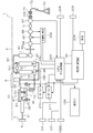
- FIG. 5 is a diagram illustrating a system configuration example of the oxygen concentrator 1.
- the double line shown in FIG. 5 shows piping that is a flow path for the raw air, oxygen, and nitrogen gas.
- a thin solid line indicates power supply or electric signal wiring.
- the main casing 2 of the oxygen concentrator 1 shown in FIG. 5 is indicated by a broken line, and the main casing 2 is a sealed container that seals the elements disposed inside.
- the main housing 2 has an air intake 5 for introducing raw material air that is outside air, an air intake filter 7, and an exhaust 6 for exhausting.
- An air intake filter 7 for removing impurities such as dust in the air is replaceably disposed in the air intake 5.
- the compressor 10 When the compressor 10 is actuated, the raw air passes through the air intake filter 7, the internal pipe 37, the intake filter / silence buffer 38, and the first connection that is connected in parallel to the intake filter / silence buffer 38. It is introduced into the compressor 10 through the pipe 40 and the second connection pipe 41.
- the raw air is introduced into the compressor 10 to become compressed air, but heat is generated when the raw air is compressed.
- the compressor 10, particularly the sleeves 11 and 12 is cooled by the air blown from the first fan 34 and the second fan 36 for cooling.
- the compressed air sent from the compressor 10 through the pipe 15 is cooled by the radiator 13.
- the radiator 13 By cooling the compressed air in this way, it is possible to suppress the temperature rise of the zeolite, which is an adsorbent that deteriorates in function at high temperatures. Thereby, it becomes possible to sufficiently function as an adsorbent for generating oxygen by adsorption of nitrogen, and oxygen can be concentrated to about 90% or more.
- the 1st adsorption cylinder 31 and the 2nd adsorption cylinder 32 are examples of the adsorption member arranged side by side, and are arranged in parallel in the lengthwise direction.
- Three-way switching valves 14B and 14C are connected to the first adsorption cylinder 31 and the second adsorption cylinder 32, respectively.
- One end of one three-way switching valve 14B is connected to the pipe 15.
- One three-way switching valve 14B and the other three-way switching valve 14C are connected to each other, and one end of the other three-way switching valve 14C is connected to the pipe 15R.
- the end of the pipe 15R reaches the exhaust port 6.
- the three-way switching valves 14B, 14C are connected to the first adsorption cylinder 31 and the second adsorption cylinder 32, respectively. Compressed air generated from the compressor 10 is alternately supplied to the first adsorption cylinder 31 and the second adsorption cylinder 32 via the pipe 15 and the three-way switching valves 14B and 14C.
- Zeolite as the catalyst adsorbent is stored in the first adsorption cylinder 31 and the second adsorption cylinder 32, respectively.
- This zeolite is, for example, an X-type zeolite having a Si 2 O 3 / Al 2 O 3 ratio of 2.0 to 3.0, and at least 88% or more of the Al 2 O 3 tetrahedral units are combined with lithium cations.
- the adsorption amount of nitrogen per unit weight can be increased.
- This zeolite preferably has a granule measurement value of less than 1 mm, and at least 88% of tetrahedral units are fused with lithium cations.
- zeolite By using zeolite, it becomes possible to reduce the amount of raw material air used for generating oxygen compared to the case of using other adsorbents. As a result, the size of the compressor 10 for generating compressed air can be further reduced, and the noise of the compressor 10 can be reduced.
- an equal pressure valve 107 including a check valve, a throttle valve, and an on-off valve is connected to the outlet side of the first adsorption cylinder 31 and the second adsorption cylinder 32.
- a joining pipe 60 is connected to the downstream side of the equal pressure valve 107, and a buffer 61 is connected to the pipe 60.
- the buffer 61 is an oxygen storage container for storing oxygen having a concentration of about 90% or more generated by separation in the first adsorption cylinder 31 and the second adsorption cylinder 32.
- a pressure regulator 62 is connected to the downstream side of the buffer 61, and the pressure regulator 62 is a regulator that automatically adjusts the oxygen pressure on the outlet side of the buffer 61 to be constant.
- a zirconia-type or ultrasonic-type oxygen concentration sensor 64 is connected to the downstream side of the pressure regulator 62 via a filter 63. The oxygen concentration sensor 64 detects oxygen concentration intermittently (10 to 30). Every minute) or continuously.
- a proportional opening valve 65 is connected to the buffer 61.
- the proportional opening valve 65 opens and closes in conjunction with the setting button operation of the oxygen flow rate setting button 102 in accordance with a signal from the flow rate control unit 202 according to a command from the central control unit 200.
- An oxygen flow rate sensor 66 is connected to the proportional opening valve 65.
- a humidifier G and an oxygen flow sensor 67 are connected to the oxygen flow sensor 66.
- An oxygen outlet 100 is connected to the subsequent stage of the oxygen flow sensor 67.
- Coupler socket 71 of nasal cannula 70 is detachably connected to oxygen outlet 100.
- the coupler socket 71 is connected to the nasal cannula 70 via the tube 72.
- the patient can inhale oxygen concentrated to about 90% or more through the nasal cannula 70, for example, at a maximum flow rate of 5 L / min.
- the AC (commercial AC) power connector 203 shown in FIG. 5 is electrically connected to the power control circuit 39, and the power control circuit 39 rectifies the AC voltage of the commercial AC power to a predetermined DC voltage.
- the built-in battery 204 is built in the main housing 2.
- the built-in battery 204 is a rechargeable secondary battery, and the built-in battery 204 can be charged by receiving power supply from the power control circuit 39.
- the central control unit 200 in FIG. 1 controls the power supply control circuit 39, so that the power supply control circuit 39 receives the power supply from the AC adapter 203, for example, and the built-in battery 204 Can be used by automatically switching to one of the second power supply states that operate by receiving power supply from the power supply.
- the built-in battery 204 is preferably a lithium ion or lithium hydrogen ion secondary battery that has little memory effect during charging and can be fully charged even during recharging, but may be a conventional nickel cadmium battery or nickel metal hydride battery.
- the central control unit 200 in FIG. 5 is electrically connected to the motor driver 210 and the fan motor driver 211.
- the central control unit 200 stores a program for switching to an optimal operation mode according to the amount of oxygen to be generated.
- the motor driver 210 and the fan motor driver 211 automatically drive the compressor 10, the first fan 34, and the second fan 36 at a high speed when a large amount of oxygen is generated according to a command from the central control unit 200. In this case, the compressor 10, the first fan 34, and the second fan 36 are controlled to rotate at a low speed.
- the central control unit 200 incorporates a ROM (read-only memo) that stores a predetermined operation program, and the central control unit 200 includes a circuit including an external storage device, a volatile memory, a temporary storage device, and a real-time clock. Electrically connected.
- the central control unit 200 can be accessed by connecting to an external communication line or the like via the communication connector 205.
- a control circuit that controls the on / off control of the three-way switching valves 14B and 14C and the equal pressure valve 107 shown in FIG. 5 to desorb unnecessary gases in the first adsorption cylinder 31 and the second adsorption cylinder 32. (Not shown), a pressure regulator 62, a flow rate control unit 202, and an oxygen concentration sensor 64 are electrically connected to the central control unit 200.
- the flow rate control unit 202 controls the proportional opening valve 65, and the oxygen flow rate values of the oxygen flow rate sensor 66 and the oxygen flow rate sensor 67 are sent to the central control unit 200.
- An oxygen flow rate setting button 102, a display unit 128, and a power switch 101 are electrically connected to the central control unit 200 shown in FIG.
- the oxygen flow rate setting button 102 can set the oxygen flow rate every time the oxygen concentrated to, for example, about 90% or more is operated in a 0.25 L step from 0.25 L (liter) per minute to a maximum of 5 L.
- a display device such as a 7-segment display liquid crystal display is used.
- the display unit 128 includes display items such as oxygen flow rate, oxygen lamp, alarm icons (tube breakage, humidifier disconnection, oxygen concentration reduction, power supply stop, remaining battery level, battery operation, charging lamp), accumulated time, and the like. Can be displayed.
- the compressor 10 shown in FIG. 5 sends compressed air into the first adsorption cylinder 31 and the second adsorption cylinder 32 by the positive pressure fluctuation adsorption method (PSA) by generating only compressed air as already described.
- the nitrogen in the compressed air is adsorbed by the adsorbent in the first adsorption cylinder 31 and the second adsorption cylinder 32.
- the driving motor 53 of the compressor 10 may be a synchronous motor, or may be a single-phase AC induction motor or a single-phase four-pole AC synchronous motor, and the type is not particularly limited. .
- the central control unit 200 shown in FIG. 5 instructs the motor driver 210, the motor driver 210 starts the driving motor 53 of the compressor 10, and the output shaft 54 of the driving motor 53 shown in FIG. . Accordingly, the piston 11P of the first head portion 51 and the piston 12P of the second head portion 52 shown in FIG. 7 reciprocate.
- the raw material air is taken in from the air intake 5 shown in FIG. 5 to remove impurities such as dust by the filter 7, and the internal pipe 37 and the intake filter / silence buffer 38 are connected in parallel.
- the air is introduced into the sleeves 11 and 12 through the suction ports 11P and 12P of the compressor 10 through the first connection pipe 40 and the second connection pipe 41.
- the raw air introduced from the pipe 37 shown in FIG. 4 to the intake filter / silence buffer 38 passes through the intake filter / silence buffer 38 to remove dust and the like, and then is reduced in parallel.
- the first connection pipe 40 and the second connection pipe 41 connected to each other can be introduced into the case part 11F through the suction port 11P of the case part 11F, and can be introduced into the case part 12F through the suction port 12P of the case part 12F.
- the piston 11P and the piston 12P in FIG. 4 are located at the top dead center, the air in the sleeve 11 and the sleeve 12 is compressed. Conversely, when the piston 11P and the piston 12P are located at the bottom dead center, the raw material air is sucked into the sleeve 11 and the sleeve 12.
- the first connection pipe 40 and the second connection pipe 41 are divided into a plurality of systems so that the introduction path of the raw material air between the intake filter / silence buffer 38 and the compressor 10 is parallel, and the intake filter / silence buffer 38 and the compressor Ten suction ports 11P and 12P are directly connected. From this, the amount of raw material air to be sent per one of the first connection pipe 40 and the second connection pipe 41 can be reduced. In other words, even if the diameters of the first pipe 40 and the second pipe 41 are set small, the pressure loss does not increase. And the compressed air which the compressor 10 shown in FIG. 5 generate
- the central control unit 200 shown in FIG. 5 gives a command to the motor driver 211 to rotate the first fan 34 and the second fan 36.
- the compressor 10 compresses the raw material air to generate compressed air
- the sleeves 11 and 12 of the compressor 10 are cooled by the blowing of the first fan 34 and the second fan 36, respectively, and the compressed air passing through the pipe 15 is It is cooled by passing through the radiator 13.
- the compressed air passes through the adsorbent in the first adsorbing cylinder 31 and the second adsorbing cylinder 32 through the pipe 15 and the three-way switching valves 14B and 14C and adsorbs nitrogen to separate oxygen.
- the buffer 61 can store oxygen having a concentration of about 90% or more generated by separation.
- the proportional opening valve 65 opens and closes in conjunction with the oxygen flow rate setting button 102. Then, oxygen is supplied to the nasal cannula 70 through the oxygen outlet portion 100. Thereby, the patient can inhale oxygen concentrated to about 90% or more through the nasal cannula 70, for example, at a maximum flow rate of 5 L / min.
- the illustrated compressor 10 includes the first pump unit 51 and the second pump unit 52, the compressor 10 is not limited thereto, and may include one pump unit or three or more pump units.
- the number of fans for cooling the compressor 10 can be arranged corresponding to the number of pumps.
- the motor for driving the compressor 10 shown in the figure is, for example, a 5L class motor, but is not limited thereto, and a motor suitable for the 3L class, for example, may be used.
- the format of the compressor is not limited sometimes, and any format can be adopted.
- SYMBOLS 1 Oxygen concentrator, 2 ... Main housing, 2F ... Front panel, 2S ... Side panel, 2R ... Rear panel, 2D ... Upper surface part, 2B ... Bottom part, 5 ... Air intake port, 6 ... Exhaust port, 10 ... Compressor, 11 ... One sleeve, 12 ... Other sleeve, 11P, 12P ... Piston, 13 ... Radiator, DESCRIPTION OF SYMBOLS 15 ... Piping, 31 ... 1st adsorption
Landscapes
- Health & Medical Sciences (AREA)
- Emergency Medicine (AREA)
- Engineering & Computer Science (AREA)
- Pulmonology (AREA)
- General Health & Medical Sciences (AREA)
- Life Sciences & Earth Sciences (AREA)
- Veterinary Medicine (AREA)
- Public Health (AREA)
- Animal Behavior & Ethology (AREA)
- Anesthesiology (AREA)
- Biomedical Technology (AREA)
- Heart & Thoracic Surgery (AREA)
- Hematology (AREA)
- Chemical & Material Sciences (AREA)
- Otolaryngology (AREA)
- Chemical Kinetics & Catalysis (AREA)
- Analytical Chemistry (AREA)
- General Chemical & Material Sciences (AREA)
- Oil, Petroleum & Natural Gas (AREA)
- Separation Of Gases By Adsorption (AREA)
- Oxygen, Ozone, And Oxides In General (AREA)
Abstract
Description
この方式の酸素濃縮装置によれば、取り込んだ原料空気をコンプレッサで圧縮して圧縮空気を発生して、吸着剤を内蔵した吸着筒に対してこの圧縮空気を供給することで該吸着剤に窒素を吸着させ酸素を生成する。そして、生成された酸素はタンクに貯めておき、減圧弁や流量設定器を介してタンクから所定流量の酸素を供給可能な状態にすることで、患者は鼻カニューラ等の器具を用いて酸素吸入ができる。
患者がやむなく外出する場合には、例えば、所定の収容容器に酸素を充填した酸素ボンベを搭載したカートを押しながら、その酸素ボンベから濃縮酸素を吸うようにしている。この酸素ボンベに対する酸素の充填は専用設備にて行なわなければならない。そこで、可搬型や移動型の酸素濃縮装置が提案されており、可搬型や移動型の酸素濃縮装置は、原料空気を取り込んで圧縮空気と減圧空気を発生するコンプレッサを備えている(特許文献1を参照)。
上記構成によれば、コンプレッサの複数の原料空気の吸入口を別々の接続配管を用いて消音器に対して直接接続することで、接続配管1本当たりの原料空気の送る量を減らすことが可能となり、圧力損失の低減により前記原料空気をロスなくコンプレッサに取り入れることが可能となる。
上記構成によれば、第1ポンプ部の原料空気の吸入口と第2ポンプの原料空気の吸入口部に対して別々の接続配管を用いて直接接続することができるので、接続配管1本当たりの原料空気の送る量を減らして圧力損失の影響を低減できる。
上記構成によれば、フィルタが圧縮空気の塵埃を除去してから圧縮空気を複数の接続配管に送ることができ、接続配管1本当たりの原料空気の送る量を減らして圧力損失の影響を低減できる。
図1は、本発明のコンプレッサを備える酸素濃縮装置の実施形態の外観を示す前側から見た斜視図である。図2は、図1の酸素濃縮装置の外観の背面図である。
図1と図2に示す酸素濃縮装置1は、好ましくは携帯型(可搬型や移動型ともいう)の酸素濃縮装置である。図1に示す酸素濃縮装置1は、例えば、酸素生成原理として圧縮空気による圧縮空気力変動吸着法(PSA)を用いている。
主筐体2は、フロントパネル2Fと、左右のサイドパネル2Sと、リアパネル2Rと、上面部2Dと、底部2Bを有している。主筐体2の内面には、防音材として、その繊維径が1~4μmのポリオレフィレン系繊維(好ましくは、ポリプロピレン繊維)と、繊維径が20~30μmのポリオレフィレン系繊維(好ましくは、ポリプロピレン繊維)とからなる不織布を用いることができる。このような不織布を用いて軽量で、かつ防音効果が得られる。図1に示すように、上面部2Dには表示部128と、酸素出口部100と、電源スイッチ101と、酸素流量設定ボタン102が配置されている。フロントパネル2Fの上部には、加湿器Gの配置部2Gが設けられている。キャスタ2Tは底部2Bの四隅部分に配置され、酸素濃縮装置1はこれらのキャスタ2を用いて移動可能になっている。
図4に示すように、配管37と、第1接続配管40と第2接続配管41との間には、吸気フィルタ兼消音バッファ(サイレンサ、消音器)38が配置されている。第1接続配管40と第2接続配管41は、実装する時の取回しをしやすくするため、熱可塑性樹脂、例えばポリウレタンで形成され、内径4~6mm、外径7~9mm、肉厚が1.3~2.0mmで、好ましくは、内径5mm、外径8mm、肉厚1.5mmである。外径が9mmより大きいと取回しの時に曲げ半径が大きくなり、内径が4mmより小さいと圧力損失が大きくなり、肉厚が1.3mmより小さいと取回しの時に折れ曲がり(キンク)しやすくなる。
配管37の端部37Bが、吸気フィルタ兼消音バッファ38の吸入側端部38Aに接続され、第1接続配管40の第1端部40Aと第2接続配管41の第1端部41Aが、吸気フィルタ兼消音バッファ38の排出側端部38Bに接続されている。そして、第1接続配管40の第2端部40Bが、ケース部11Fの吸入口(吸入ポート)11Pに接続され、第2接続配管41の第2端部41Bが、ケース部12Fの吸入口(吸入ポート)12Pに接続されている。
吸気フィルタ兼消音バッファ38とコンプレッサ10の間における原料空気の導入経路を複数に分けて、吸気フィルタ兼消音バッファ38とコンプレッサ10の間では、第1接続配管40と第2接続配管41が並列に接続されている。言いかえれば、第1接続配管40と第2接続配管41は、吸気フィルタ兼消音バッファ38とコンプレッサ10の吸入口11P、12Pを直接接続している。
これにより、配管37から吸気フィルタ兼消音バッファ38に導入された原料空気は、吸気フィルタ兼消音バッファ38を通過して、吸気フィルタにより塵埃等が除去されるとともに騒音が低減された後に、第1接続配管40と第2接続配管41に分かれて、ケース部11Fの吸入口11Pを通じてケース部11F内に導入できるとともに、ケース部12Fの吸入口12Pを通じてケース部12F内に導入できるようになっている。
ヘッドカバー11H、12Hは、共通して配管15に接続され、発生した圧縮空気はこの配管15を通じて送られる。この配管15の途中には放熱用のラジエータ13が配置されている。
ここで、接続配管は、この実施形態では、第1接続配管40と第2接続配管41の2本設けられているが、接続配管は、スリーブ(シリンダ)の数の対応して、同じ数だけ設けられるものであり、スリーブの数が増えれば、その分、個別に接続される接続配管も増加される。
図5は、酸素濃縮装置1のシステム構成例を示す図である。
図5に示す二重線は、原料空気、酸素、窒素ガスの流路となる配管を示している。また、細い実線は電源供給または電気信号の配線を示している。図5に示す酸素濃縮装置1の主筐体2は破線で示しており、この主筐体2は内部に配置された要素を密閉している密閉容器である。
このように圧縮空気を冷却することで、高温では機能低下してしまう吸着剤であるゼオライトの昇温を抑制できる。これにより、窒素の吸着により酸素を生成するための吸着剤として十分に機能できるようになり、酸素を90%程度以上にまで濃縮できる。
3方向切換弁14B、14Cは、第1吸着筒体31と第2吸着筒体32にそれぞれ対応して接続されている。コンプレッサ10から発生する圧縮空気は、配管15と3方向切換弁14B、14Cを介して、第1吸着筒体31と第2吸着筒体32に対して交互に供給される。
酸素出口部100には、鼻カニューラ70のカプラソケット71が着脱可能に接続される。カプラソケット71は、チューブ72を介して鼻カニューラ70に接続されている。患者は、鼻カニューラ70を経て、例えば最大流量5L/分の流量で、約90%程度以上に濃縮された酸素の吸入が可能である。
図5に示すAC(商用交流)電源のコネクタ203は、電源制御回路39に電気的に接続され、電源制御回路39は商用交流電源の交流電圧を所定の直流電圧に整流する。内蔵電池204は、主筐体2に内蔵されている。内蔵電池204は、繰り返し充電可能な2次電池であり、内蔵電池204は電源制御回路39からの電力供給を受けて充電できる。
図5に示す3方向切換弁14B、14Cと均等圧弁107とをオンオフ制御することで、第1吸着筒体31と第2吸着筒体32内の不要ガスを脱離させるように制御する制御回路(図示せず)と、圧力調整器62と、流量制御部202と、酸素濃度センサ64が、中央制御部200に電気的に接続されている。流量制御部202は、比例開度弁65を制御し、酸素流量センサ66と酸素流量センサ67の酸素流量値は、中央制御部200に送られる。図5に示す中央制御部200には、酸素流量設定ボタン102と、表示部128と、電源スイッチ101が電気的に接続されている。
図5に示す中央制御部200がモータドライバ210に指令して、モータドライバ210がコンプレッサ10の駆動用モータ53を始動して、図7に示す駆動用モータ53の出力軸54が連続回転をする。これにより、図7に示す第1ヘッド部51のピストン11Pと第2ヘッド部52のピストン12Pは往復移動する。
第1接続配管40と第2接続配管41は、吸気フィルタ兼消音バッファ38とコンプレッサ10の間における原料空気の導入経路を並列になるように複数系統に分けて、吸気フィルタ兼消音バッファ38とコンプレッサ10の吸入口11P、12Pを直接接続している。このことから、第1接続配管40と第2接続配管41の1本当たりの送るべき原料空気量を減らすことができる。言いかえれば、第1配管40と第2配管41の直径を小さく設定しても圧力損失が増加せずに済む。
そして、図5に示すコンプレッサ10が発生する圧縮空気は、配管15を介して、第1吸着筒体13と第2吸着筒体32側に供給できる。
図示したコンプレッサ10は第1ポンプ部51と第2ポンプ部52を有しているが、これに限らず1つのポンプ部あるいは3つ以上のポンプ部を備えていても良い。コンプレッサ10を冷却するファンの数は、ポンプの数に対応して配置することができる。図に示すコンプレッサ10の駆動用モータは、例えば5Lクラスのモータであるが、これに限らず例えば3Lクラス等に適するモータを用いても良い。コンプレッサの形式は時に限定されず、任意の形式が採用できる。
Claims (3)
- 原料空気を吸入するための複数の吸入口を有し、吸入した前記原料空気を圧縮して圧縮空気を発生するコンプレッサと、
前記コンプレッサの前段には、吸入口からの騒音を低減するための消音器が設けられ、前記コンプレッサからの複数の吸入口と前記消音器とが個別に接続されることを特徴とする酸素濃縮装置。 - 前記コンプレッサは、ピストンをスリーブ内で往復移動させることで前記原料空気を圧縮して前記圧縮空気をそれぞれ発生する第1ポンプ部と第2ポンプ部を有し、
前記第1ポンプと前記第2ポンプ部にはそれぞれ前記吸入口が設けられていることを特徴とする請求項1に記載の酸素濃縮装置。 - 前記消音器は、前記圧縮空気の塵埃を除去するフィルタを有することを特徴とする請求項1または請求項2に記載の酸素濃縮装置。
Priority Applications (2)
| Application Number | Priority Date | Filing Date | Title |
|---|---|---|---|
| CN2010800579103A CN102711891A (zh) | 2009-12-18 | 2010-11-29 | 氧气浓缩装置 |
| US13/516,944 US8636838B2 (en) | 2009-12-18 | 2010-11-29 | Oxygen concentrator |
Applications Claiming Priority (2)
| Application Number | Priority Date | Filing Date | Title |
|---|---|---|---|
| JP2009-288266 | 2009-12-18 | ||
| JP2009288266A JP5495766B2 (ja) | 2009-12-18 | 2009-12-18 | 酸素濃縮装置 |
Publications (1)
| Publication Number | Publication Date |
|---|---|
| WO2011074192A1 true WO2011074192A1 (ja) | 2011-06-23 |
Family
ID=44166967
Family Applications (1)
| Application Number | Title | Priority Date | Filing Date |
|---|---|---|---|
| PCT/JP2010/006946 Ceased WO2011074192A1 (ja) | 2009-12-18 | 2010-11-29 | 酸素濃縮装置 |
Country Status (5)
| Country | Link |
|---|---|
| US (1) | US8636838B2 (ja) |
| JP (1) | JP5495766B2 (ja) |
| CN (1) | CN102711891A (ja) |
| TW (1) | TWI424862B (ja) |
| WO (1) | WO2011074192A1 (ja) |
Cited By (1)
| Publication number | Priority date | Publication date | Assignee | Title |
|---|---|---|---|---|
| WO2014051016A1 (ja) * | 2012-09-26 | 2014-04-03 | 帝人ファーマ株式会社 | コンプレッサ |
Families Citing this family (18)
| Publication number | Priority date | Publication date | Assignee | Title |
|---|---|---|---|---|
| US9592360B2 (en) * | 2011-04-22 | 2017-03-14 | Inogen, Inc. | Gas concentrator with removable cartridge adsorbent beds |
| US10695520B2 (en) | 2011-04-22 | 2020-06-30 | Inogen, Inc. | Gas concentrator with removable cartridge adsorbent beds |
| TWI590847B (zh) | 2012-09-20 | 2017-07-11 | Teijin Pharma Ltd | Oxygen concentration device |
| WO2015109236A1 (en) * | 2014-01-16 | 2015-07-23 | Ahmad Samir S | Oxygen concentrator for high pressure oxygen delivery with oxygen circulation loop and improved portability |
| US20160352204A1 (en) * | 2014-08-08 | 2016-12-01 | Johnson Electric S.A. | Refrigeration apparatus |
| US10315002B2 (en) | 2015-03-24 | 2019-06-11 | Ventec Life Systems, Inc. | Ventilator with integrated oxygen production |
| US11247015B2 (en) | 2015-03-24 | 2022-02-15 | Ventec Life Systems, Inc. | Ventilator with integrated oxygen production |
| US10773049B2 (en) | 2016-06-21 | 2020-09-15 | Ventec Life Systems, Inc. | Cough-assist systems with humidifier bypass |
| US11083865B2 (en) * | 2017-05-30 | 2021-08-10 | Inogen, Inc. | Compact portable oxygen concentrator |
| EP4470589A3 (en) | 2018-05-13 | 2025-02-19 | Ventec Life Systems, Inc. | Portable medical ventilator system using portable oxygen |
| USD854691S1 (en) * | 2018-05-22 | 2019-07-23 | Ngk Spark Plug Co., Ltd. | Medical oxygen concentrator |
| CN109854946A (zh) * | 2019-02-11 | 2019-06-07 | 重庆叶源信商贸有限责任公司 | 一种常温下自动加压充填氧气的方法 |
| JP2023548463A (ja) | 2020-11-06 | 2023-11-17 | ベンテック ライフ システムズ, インコーポレイテッド | 呼吸療法データ管理システム、デバイス、および方法 |
| JP2024503250A (ja) | 2020-12-21 | 2024-01-25 | ベンテック ライフ システムズ, インコーポレイテッド | 一体化された酸素送達を有するベンチレータシステムおよび関連付けられたデバイスおよび方法 |
| CN114247266B (zh) * | 2022-03-01 | 2022-05-06 | 华能平凉发电有限责任公司 | 一种氧弹更换保护装置 |
| USD1069119S1 (en) * | 2024-11-06 | 2025-04-01 | Shenzhen Deda Medical Technology Group Co., Ltd. | Oxygen concentrator |
| USD1069120S1 (en) * | 2024-11-08 | 2025-04-01 | Shenzhen Deda Medical Technology Group Co., Ltd. | Oxygen concentrator |
| USD1083104S1 (en) * | 2024-11-21 | 2025-07-08 | Shenzhen Deda Medical Technology Group Co., Ltd. | Oxygen concentrator |
Citations (3)
| Publication number | Priority date | Publication date | Assignee | Title |
|---|---|---|---|---|
| JP2003235982A (ja) * | 2002-02-18 | 2003-08-26 | Teijin Ltd | 医療用圧力変動吸着型酸素濃縮装置 |
| JP2005111016A (ja) * | 2003-10-09 | 2005-04-28 | Terumo Corp | 酸素濃縮装置 |
| JP2008144714A (ja) * | 2006-12-12 | 2008-06-26 | Ngk Spark Plug Co Ltd | コンプレッサ、真空ポンプ、圧縮・真空複合機、及び酸素濃縮器 |
Family Cites Families (23)
| Publication number | Priority date | Publication date | Assignee | Title |
|---|---|---|---|---|
| US4418788A (en) | 1981-04-13 | 1983-12-06 | Mitco Corporation | Branch take-off and silencer for an air distribution system |
| US4450933A (en) * | 1982-09-24 | 1984-05-29 | Kioritz Corporation | Suction silencer |
| JPS61131756A (ja) * | 1984-11-30 | 1986-06-19 | 鳥取大学長 | 呼吸同調送気式濃縮酸素供給装置 |
| AT386545B (de) * | 1986-07-11 | 1988-09-12 | Voest Alpine Ag | Verfahren zum reinigen von gasen sowie vorrichtung zur durchfuehrung dieses verfahrens |
| US4986170A (en) * | 1989-09-21 | 1991-01-22 | M & I Heat Transfer Products Ltd. | Air handling system |
| US5370728A (en) * | 1993-09-07 | 1994-12-06 | Praxair Technology, Inc. | Single bed pressure swing adsorption system and process |
| JP3640412B2 (ja) | 1994-05-17 | 2005-04-20 | 芝浦メカトロニクス株式会社 | 往復動ポンプユニット |
| US5658371A (en) * | 1995-11-06 | 1997-08-19 | Praxair Technology, Inc. | Single bed pressure swing adsorption process for recovery of oxygen from air |
| US5656068A (en) * | 1996-02-29 | 1997-08-12 | Praxair Technology, Inc. | Large capacity vacuum pressure swing adsorption process and system |
| US5858062A (en) * | 1997-02-10 | 1999-01-12 | Litton Systems, Inc. | Oxygen concentrator |
| JP2001120662A (ja) * | 1999-10-29 | 2001-05-08 | Sumitomo Bakelite Co Ltd | 酸素濃縮装置 |
| JP3955426B2 (ja) * | 2000-03-31 | 2007-08-08 | 日本特殊陶業株式会社 | 酸素濃縮装置 |
| US6702880B2 (en) * | 2002-05-17 | 2004-03-09 | Porous Media Corporation | Inlet silencer/filter for an oxygen concentrator |
| US7279029B2 (en) * | 2004-05-21 | 2007-10-09 | Air Products And Chemicals, Inc. | Weight-optimized portable oxygen concentrator |
| US7455717B2 (en) * | 2004-10-25 | 2008-11-25 | Invacare Corporation | Apparatus and method of providing concentrated product gas |
| JPWO2006121139A1 (ja) * | 2005-05-06 | 2008-12-18 | 帝人ファーマ株式会社 | 消音器及びそれを備えた酸素濃縮装置 |
| JP4330576B2 (ja) * | 2005-10-28 | 2009-09-16 | サンデン株式会社 | 圧縮機 |
| US7510601B2 (en) * | 2005-12-20 | 2009-03-31 | Air Products And Chemicals, Inc. | Portable medical oxygen concentrator |
| JP2008148859A (ja) * | 2006-12-15 | 2008-07-03 | Terumo Corp | 可搬型酸素濃縮装置 |
| JP5184850B2 (ja) * | 2007-09-14 | 2013-04-17 | 株式会社ゼリアエコテック | 気体分離装置並びに酸素濃縮装置及びエアロバイク |
| JP5303150B2 (ja) * | 2008-01-31 | 2013-10-02 | 株式会社三共 | 遊技機 |
| JP5112897B2 (ja) | 2008-02-06 | 2013-01-09 | 日本特殊陶業株式会社 | 酸素濃縮器 |
| JP2011143107A (ja) * | 2010-01-15 | 2011-07-28 | Terumo Corp | 酸素濃縮装置 |
-
2009
- 2009-12-18 JP JP2009288266A patent/JP5495766B2/ja active Active
-
2010
- 2010-11-29 WO PCT/JP2010/006946 patent/WO2011074192A1/ja not_active Ceased
- 2010-11-29 CN CN2010800579103A patent/CN102711891A/zh active Pending
- 2010-11-29 US US13/516,944 patent/US8636838B2/en not_active Expired - Fee Related
- 2010-12-17 TW TW099144387A patent/TWI424862B/zh not_active IP Right Cessation
Patent Citations (3)
| Publication number | Priority date | Publication date | Assignee | Title |
|---|---|---|---|---|
| JP2003235982A (ja) * | 2002-02-18 | 2003-08-26 | Teijin Ltd | 医療用圧力変動吸着型酸素濃縮装置 |
| JP2005111016A (ja) * | 2003-10-09 | 2005-04-28 | Terumo Corp | 酸素濃縮装置 |
| JP2008144714A (ja) * | 2006-12-12 | 2008-06-26 | Ngk Spark Plug Co Ltd | コンプレッサ、真空ポンプ、圧縮・真空複合機、及び酸素濃縮器 |
Cited By (3)
| Publication number | Priority date | Publication date | Assignee | Title |
|---|---|---|---|---|
| WO2014051016A1 (ja) * | 2012-09-26 | 2014-04-03 | 帝人ファーマ株式会社 | コンプレッサ |
| JPWO2014051016A1 (ja) * | 2012-09-26 | 2016-08-22 | 帝人ファーマ株式会社 | コンプレッサ |
| US10087919B2 (en) | 2012-09-26 | 2018-10-02 | Teijin Pharma Limited | Air compressor with improved noise reduction performance |
Also Published As
| Publication number | Publication date |
|---|---|
| TW201127429A (en) | 2011-08-16 |
| US20120304867A1 (en) | 2012-12-06 |
| JP2011125561A (ja) | 2011-06-30 |
| US8636838B2 (en) | 2014-01-28 |
| CN102711891A (zh) | 2012-10-03 |
| JP5495766B2 (ja) | 2014-05-21 |
| TWI424862B (zh) | 2014-02-01 |
Similar Documents
| Publication | Publication Date | Title |
|---|---|---|
| JP5495766B2 (ja) | 酸素濃縮装置 | |
| JP5314063B2 (ja) | デュアルモード式医療用酸素濃縮器 | |
| JP7665452B2 (ja) | より高い酸素流量能力を可能にする着用可能な酸素生成機およびドッキング・ステーション | |
| EP2524714A1 (en) | Oxygen concentration device | |
| US8864477B2 (en) | Compressor and oxygen concentrator | |
| JP5536318B2 (ja) | コンプレッサ及びこれを用いた酸素濃縮装置 | |
| EP1568391A1 (en) | Dual mode medical oxygen concentrator | |
| JP2010017476A (ja) | コンプレッサ及びこれを用いた酸素濃縮装置 | |
| JP2011143023A (ja) | 酸素濃縮装置 | |
| JP2008212206A (ja) | 酸素濃縮装置 | |
| JP5443023B2 (ja) | コンプレッサおよび酸素濃縮装置 | |
| JP2008136663A (ja) | 酸素濃縮装置 | |
| JP5048313B2 (ja) | 酸素濃縮装置 | |
| JP2008148859A (ja) | 可搬型酸素濃縮装置 | |
| JP2010209762A (ja) | コンプレッサおよび酸素濃縮装置 | |
| JP5016845B2 (ja) | 医療用酸素濃縮装置及びその作動方法 | |
| JP2010017477A (ja) | コンプレッサ及びこれを用いた酸素濃縮装置 | |
| JP5578796B2 (ja) | 酸素濃縮装置 | |
| JP5026775B2 (ja) | 酸素濃縮装置 | |
| JP2010207351A (ja) | コンプレッサおよび酸素濃縮装置 | |
| JP2010207350A (ja) | コンプレッサおよび酸素濃縮装置 | |
| JP3157648U (ja) | 可搬型酸素濃縮装置 | |
| JP2010209763A (ja) | コンプレッサおよび酸素濃縮装置 | |
| JP2016135201A (ja) | 酸素濃縮装置とその電源回路の電源制御方法 | |
| JP2016135203A (ja) | 酸素濃縮装置と送風ファンの制御方法 |
Legal Events
| Date | Code | Title | Description |
|---|---|---|---|
| WWE | Wipo information: entry into national phase |
Ref document number: 201080057910.3 Country of ref document: CN |
|
| 121 | Ep: the epo has been informed by wipo that ep was designated in this application |
Ref document number: 10837229 Country of ref document: EP Kind code of ref document: A1 |
|
| 121 | Ep: the epo has been informed by wipo that ep was designated in this application |
Ref document number: 10837229 Country of ref document: EP Kind code of ref document: A1 |
|
| NENP | Non-entry into the national phase |
Ref country code: DE |
|
| WWE | Wipo information: entry into national phase |
Ref document number: 13516944 Country of ref document: US |
|
| 122 | Ep: pct application non-entry in european phase |
Ref document number: 10837229 Country of ref document: EP Kind code of ref document: A1 |