WO2011068031A1 - 映像表示装置、シャッタ眼鏡、映像表示システム、および通信方法 - Google Patents
映像表示装置、シャッタ眼鏡、映像表示システム、および通信方法 Download PDFInfo
- Publication number
- WO2011068031A1 WO2011068031A1 PCT/JP2010/070488 JP2010070488W WO2011068031A1 WO 2011068031 A1 WO2011068031 A1 WO 2011068031A1 JP 2010070488 W JP2010070488 W JP 2010070488W WO 2011068031 A1 WO2011068031 A1 WO 2011068031A1
- Authority
- WO
- WIPO (PCT)
- Prior art keywords
- display device
- count value
- shutter glasses
- unit
- reception
- Prior art date
- Legal status (The legal status is an assumption and is not a legal conclusion. Google has not performed a legal analysis and makes no representation as to the accuracy of the status listed.)
- Ceased
Links
Images


Classifications
-
- G—PHYSICS
- G09—EDUCATION; CRYPTOGRAPHY; DISPLAY; ADVERTISING; SEALS
- G09G—ARRANGEMENTS OR CIRCUITS FOR CONTROL OF INDICATING DEVICES USING STATIC MEANS TO PRESENT VARIABLE INFORMATION
- G09G5/00—Control arrangements or circuits for visual indicators common to cathode-ray tube indicators and other visual indicators
- G09G5/12—Synchronisation between the display unit and other units, e.g. other display units, video-disc players
-
- G—PHYSICS
- G09—EDUCATION; CRYPTOGRAPHY; DISPLAY; ADVERTISING; SEALS
- G09G—ARRANGEMENTS OR CIRCUITS FOR CONTROL OF INDICATING DEVICES USING STATIC MEANS TO PRESENT VARIABLE INFORMATION
- G09G3/00—Control arrangements or circuits, of interest only in connection with visual indicators other than cathode-ray tubes
- G09G3/20—Control arrangements or circuits, of interest only in connection with visual indicators other than cathode-ray tubes for presentation of an assembly of a number of characters, e.g. a page, by composing the assembly by combination of individual elements arranged in a matrix no fixed position being assigned to or needed to be assigned to the individual characters or partial characters
-
- G—PHYSICS
- G09—EDUCATION; CRYPTOGRAPHY; DISPLAY; ADVERTISING; SEALS
- G09G—ARRANGEMENTS OR CIRCUITS FOR CONTROL OF INDICATING DEVICES USING STATIC MEANS TO PRESENT VARIABLE INFORMATION
- G09G3/00—Control arrangements or circuits, of interest only in connection with visual indicators other than cathode-ray tubes
- G09G3/001—Control arrangements or circuits, of interest only in connection with visual indicators other than cathode-ray tubes using specific devices not provided for in groups G09G3/02 - G09G3/36, e.g. using an intermediate record carrier such as a film slide; Projection systems; Display of non-alphanumerical information, solely or in combination with alphanumerical information, e.g. digital display on projected diapositive as background
- G09G3/003—Control arrangements or circuits, of interest only in connection with visual indicators other than cathode-ray tubes using specific devices not provided for in groups G09G3/02 - G09G3/36, e.g. using an intermediate record carrier such as a film slide; Projection systems; Display of non-alphanumerical information, solely or in combination with alphanumerical information, e.g. digital display on projected diapositive as background to produce spatial visual effects
-
- G—PHYSICS
- G09—EDUCATION; CRYPTOGRAPHY; DISPLAY; ADVERTISING; SEALS
- G09G—ARRANGEMENTS OR CIRCUITS FOR CONTROL OF INDICATING DEVICES USING STATIC MEANS TO PRESENT VARIABLE INFORMATION
- G09G3/00—Control arrangements or circuits, of interest only in connection with visual indicators other than cathode-ray tubes
- G09G3/20—Control arrangements or circuits, of interest only in connection with visual indicators other than cathode-ray tubes for presentation of an assembly of a number of characters, e.g. a page, by composing the assembly by combination of individual elements arranged in a matrix no fixed position being assigned to or needed to be assigned to the individual characters or partial characters
- G09G3/34—Control arrangements or circuits, of interest only in connection with visual indicators other than cathode-ray tubes for presentation of an assembly of a number of characters, e.g. a page, by composing the assembly by combination of individual elements arranged in a matrix no fixed position being assigned to or needed to be assigned to the individual characters or partial characters by control of light from an independent source
- G09G3/36—Control arrangements or circuits, of interest only in connection with visual indicators other than cathode-ray tubes for presentation of an assembly of a number of characters, e.g. a page, by composing the assembly by combination of individual elements arranged in a matrix no fixed position being assigned to or needed to be assigned to the individual characters or partial characters by control of light from an independent source using liquid crystals
-
- H—ELECTRICITY
- H04—ELECTRIC COMMUNICATION TECHNIQUE
- H04N—PICTORIAL COMMUNICATION, e.g. TELEVISION
- H04N13/00—Stereoscopic video systems; Multi-view video systems; Details thereof
- H04N13/30—Image reproducers
- H04N13/332—Displays for viewing with the aid of special glasses or head-mounted displays [HMD]
- H04N13/341—Displays for viewing with the aid of special glasses or head-mounted displays [HMD] using temporal multiplexing
-
- H—ELECTRICITY
- H04—ELECTRIC COMMUNICATION TECHNIQUE
- H04N—PICTORIAL COMMUNICATION, e.g. TELEVISION
- H04N13/00—Stereoscopic video systems; Multi-view video systems; Details thereof
- H04N13/30—Image reproducers
- H04N13/398—Synchronisation thereof; Control thereof
-
- G—PHYSICS
- G09—EDUCATION; CRYPTOGRAPHY; DISPLAY; ADVERTISING; SEALS
- G09G—ARRANGEMENTS OR CIRCUITS FOR CONTROL OF INDICATING DEVICES USING STATIC MEANS TO PRESENT VARIABLE INFORMATION
- G09G2330/00—Aspects of power supply; Aspects of display protection and defect management
- G09G2330/02—Details of power systems and of start or stop of display operation
- G09G2330/021—Power management, e.g. power saving
-
- G—PHYSICS
- G09—EDUCATION; CRYPTOGRAPHY; DISPLAY; ADVERTISING; SEALS
- G09G—ARRANGEMENTS OR CIRCUITS FOR CONTROL OF INDICATING DEVICES USING STATIC MEANS TO PRESENT VARIABLE INFORMATION
- G09G5/00—Control arrangements or circuits for visual indicators common to cathode-ray tube indicators and other visual indicators
- G09G5/003—Details of a display terminal, the details relating to the control arrangement of the display terminal and to the interfaces thereto
-
- H—ELECTRICITY
- H04—ELECTRIC COMMUNICATION TECHNIQUE
- H04N—PICTORIAL COMMUNICATION, e.g. TELEVISION
- H04N13/00—Stereoscopic video systems; Multi-view video systems; Details thereof
- H04N13/30—Image reproducers
- H04N2013/40—Privacy aspects, i.e. devices showing different images to different viewers, the images not being viewpoints of the same scene
- H04N2013/403—Privacy aspects, i.e. devices showing different images to different viewers, the images not being viewpoints of the same scene the images being monoscopic
Definitions
- the present invention relates to a video display system using shutter glasses, and a video display device, shutter glasses, and a communication method that are preferably used in such a system.
- the video display device based on the time-division drive method is a video display device that sequentially switches and outputs a plurality of video streams.
- a time-division stereoscopic image display system using so-called shutter glasses see, for example, Patent Documents 1 to 3
- a plurality of observers using shutter glasses for example, a multi-video display system that observes different videos without dividing the screen.
- the time-division stereoscopic video display system alternately displays the left-eye video and the right-eye video on the entire screen in a very short cycle, and at the same time, synchronizes with the display cycle of the left-eye video and the right-eye video.
- a video display system using a stereoscopic video display device that separately provides video to the right eye.
- the left eye portion of the shutter glasses transmits light and the right eye portion blocks light while the left eye image is displayed.
- the right eye of the shutter glasses transmits light and the left eye blocks light.
- the stereoscopic video display device performs time division display of the left eye video and the right eye video at 96 Hz, 100 Hz, and 120 Hz, respectively, with respect to the signals of 24 Hz, 50 Hz, and 60 Hz, and the shutter.
- the glasses perform the opening / closing operation of the liquid crystal shutter at the opening / closing frequencies of 48 Hz, 50 Hz, and 60 Hz, respectively.
- the time-division stereoscopic video display system needs to provide the video separately for the left eye and the right eye in synchronization with the display cycle of the video for the left eye and the video for the right eye. It is necessary to notify the opening / closing timing of the shutter of the glasses.
- a method using infrared communication or wireless communication can be considered.
- a specific method of the wireless communication there is a method using a standard used for wireless communication between a remote controller for remotely controlling the video display device and the video display device, for example, IEEE 802.15.4.
- a standard used for wireless communication between a remote controller for remotely controlling the video display device and the video display device, for example, IEEE 802.15.4.
- the present invention has been made in view of such a problem, and an object thereof is to provide a video display device, shutter glasses, a video display system, and a communication method capable of suppressing power consumption.
- the video display device of the present invention includes a display unit, a clock counter, and a transmission unit.
- the display unit displays video in a time-sharing manner with a predetermined display cycle.
- the transmission unit sets the value of the clock counter used for setting the reception time slot for shutter glasses that transmit or block the display video of the display unit by the opening / closing operation based on the control information received in the intermittent reception time slot. The transmission time count value based on this is transmitted.
- the shutter glasses of the present invention include a shutter, a clock counter, a receiving unit, and a control unit.
- the shutter transmits or blocks an image displayed on the image display device at a predetermined display cycle by an opening / closing operation based on control information.
- the receiving unit acquires the value of the clock counter when the transmission time count value based on the value of the built-in clock counter of the video display device is received from the video display device as the reception time count value.
- the control unit sets intermittent reception time slots for the reception unit to receive control information from the video display device based on the transmission time count value and the reception time count value.
- the video display system of the present invention includes the above-described video display device of the present invention and the shutter glasses of the present invention.
- a video display device that displays video transmits a transmission time count value based on a value of a clock counter, and the video display device performs an open / close operation based on control information received in intermittent reception time slots.
- the shutter glasses that transmit or block the display video acquire the value of its own clock counter when receiving the transmission time count value from the video display device as the reception time count value, and based on the transmission time count value and the reception time count value
- the reception unit sets intermittent reception time slots for receiving control information from the video display device.
- the transmission time count value is transmitted from the video display device to the shutter glasses.
- a reception time slot is set based on the transmission time count value and the reception time count value acquired correspondingly.
- the shutter glasses receive control information transmitted from the video display device intermittently by the reception time slot, and operate so as to be in a sleep state during other periods.
- control information includes, for example, an opening / closing timing value based on the value of the clock counter for instructing the opening / closing timing of the shutter glasses.
- the transmission unit transmits the opening / closing timing value at a cycle longer than the display cycle, for example.
- the transmission unit may transmit the opening / closing timing value together with the transmission time count value, for example. Further, for example, the transmission unit may transmit the transmission time count value to the shutter glasses based on a request from the shutter glasses.
- the control information includes, for example, a first opening / closing timing value based on the value of the built-in clock counter of the video display device for instructing the opening / closing timing of the shutter glasses.
- the receiving unit receives the first opening / closing timing value at a cycle longer than the display cycle, for example.
- the receiving unit may receive the first opening / closing timing value together with the transmission time count value from the video display device, for example.
- the opening / closing timing for converting the first opening / closing timing value received by the receiving unit into the second opening / closing timing value based on the value of the clock counter.
- a calculation unit may be provided, and the shutter may perform an opening / closing operation based on the second opening / closing timing value.
- the reception unit can operate in a continuous reception mode in which reception is possible at any time, and in the continuous reception mode, when the reception unit continuously receives a transmission time count value a predetermined number of times, in an intermittent reception time slot. You may make it transfer to the intermittent reception mode which performs reception operation
- the control unit obtains and receives the next transmission timing from the video display device based on the transmission time count value and the reception time count value.
- a time slot may be set.
- the receiving unit for example, divides the transmission time count value received every predetermined number of receptions and the corresponding reception time count value into a plurality of times together with the last received transmission time count value and the corresponding reception time count value.
- the control unit holds the transmission time count value and the reception time count value corresponding to the first and last reception among the transmission time count value and the reception time count value for a plurality of times held by the reception unit,
- the reception time slot may be set by obtaining the next transmission timing from the video display device.
- the number of times of holding the transmission time count value and the reception time count value can be, for example, three.
- the shutter glasses of the present invention further include, for example, a frequency synchronization processing unit that performs processing so that its own clock frequency matches the clock frequency of the video display device based on the transmission time count value and the reception time count value; And a counter setting unit that matches the value of the counter with the value of the built-in clock counter of the video display device.
- the shutter glasses further include, for example, a synchronization request unit that requests the video display device to synchronize the clock frequency with the video display device, and the frequency synchronization processing unit performs video based on a request from the synchronization request unit. Processing may be performed based on a transmission time count value transmitted by the display device and a reception time count value corresponding to the transmission time count value.
- the reception unit may operate in a continuous reception mode in which reception is possible whenever the value of the clock counter does not match the value of the built-in clock counter of the video display device.
- the counter setting unit requests the video display device to transmit the first opening / closing timing value when the receiving unit cannot continuously receive the first opening / closing timing value a predetermined number of times from the video display device. You may make it do. For example, if the first setting timing value is not received from the video display device even if the counter setting unit requests continuously a predetermined number of times, the synchronization request unit resynchronizes the clock frequency to the video display device. You may make it request.
- the receiving unit may receive an opening time value based on a value of a built-in clock counter of the video display device for instructing an opening time of the shutter from the video display device together with the first opening / closing timing value. Good.
- the receiving unit may receive the first opening / closing timing value from the video display device by wireless communication, for example.
- wireless communication conforming to the IEEE 802.15.4 standard can be used.
- the shutter glasses are provided with intermittent reception time slots when receiving control information from the video display device. Power can be reduced.
- FIG. 1 is an explanatory diagram illustrating a configuration example of a video display system according to an embodiment of the present invention.
- FIG. 2 is a block diagram illustrating a configuration example of the display device according to the first embodiment.
- FIG. 3 is a block diagram illustrating a configuration example of a shutter control unit according to the video display system according to the first embodiment.
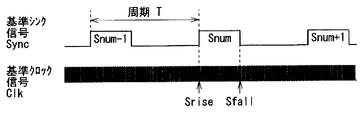
- FIG. 4 is a timing waveform chart for explaining the reference sync signal according to the first embodiment.
- FIG. 5 is a block diagram illustrating a configuration example of a main part of the shutter control unit according to the first embodiment.
- FIG. 6 is an explanatory diagram illustrating an operation example of the video display system according to the first embodiment.
- FIG. 1 is an explanatory diagram illustrating a configuration example of a video display system according to an embodiment of the present invention.
- FIG. 2 is a block diagram illustrating a configuration example of the display device according to the first embodiment.
- FIG. 3 is a block diagram illustrating a configuration example of a shutter control unit
- FIG. 7 is an explanatory diagram illustrating an example of opening / closing timing of the shutter glasses according to the first embodiment.
- FIG. 8 is a flowchart illustrating an operation example of the video display system according to the first embodiment.
- FIG. 9 is a sequence diagram illustrating an operation example of the video display system according to the first embodiment.
- FIG. 10 is a block diagram illustrating a configuration example of the shutter control unit of the display device according to the second embodiment.
- FIG. 11 is a block diagram illustrating a configuration example of a shutter control unit of the shutter glasses according to the second embodiment.
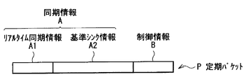
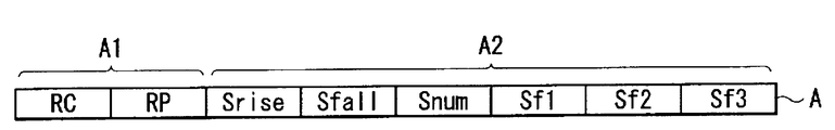
- FIG. 12 is an explanatory diagram illustrating a configuration example of a regular packet according to the second embodiment.
- FIG. 13A is a diagram for describing a configuration example of the synchronization information shown in FIG. FIG.
- FIG. 13B is a table for explaining a configuration example of the synchronization information shown in FIG.
- FIG. 13C is a diagram for describing a configuration example of the synchronization information illustrated in FIG. 12.
- FIG. 14 is a table for explaining a configuration example of the control information shown in FIG.
- FIG. 15 is an explanatory diagram illustrating a configuration example of a register related to the shutter control unit illustrated in FIG. 11.
- FIG. 16 is a sequence diagram illustrating an operation example of the video display system according to the second embodiment.
- FIG. 17 is a sequence diagram illustrating another operation example of the video display system according to the second embodiment.
- FIG. 18 is a sequence diagram illustrating another operation example of the video display system according to the second embodiment.
- FIG. 19 is a flowchart illustrating an operation example of the video display system according to the second embodiment.
- FIG. 20 is an explanatory diagram for explaining transmission and reception of a regular packet according to the second embodiment.
- FIG. 21 is a flowchart illustrating another operation example of the video display system according to the second embodiment.
- FIG. 22 is a flowchart illustrating another operation example of the video display system according to the second embodiment.
- FIG. 23 is a block diagram illustrating a configuration example of a shutter control unit of shutter glasses according to a modification of the second embodiment.
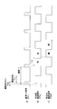
- FIG. 24 is a timing waveform diagram for explaining a reference sync signal according to a modification.
- FIG. 25 is a timing waveform diagram for explaining a reference sync signal according to another modification.
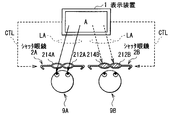
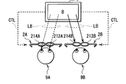
- FIG. 26A is a schematic diagram illustrating an operation example of a video display system according to a modification.
- FIG. 26B is a schematic diagram illustrating an operation example of the video display system according to the modification.
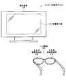
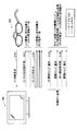
- FIG. 1 shows a configuration example of the video display system 10.
- FIG. 1 also shows the display device 100 and shutter glasses 200 used by the observer to perceive an image displayed by the display device 100 as a three-dimensional image.
- the display device 100 and the shutter glasses 200 constitute the video display system 10.
- the display apparatus 100 shown in FIG. 1 includes an image display unit 110 that displays an image.
- the display device 100 is a device capable of not only displaying a normal image on the image display unit 110 but also displaying a three-dimensional image on the image display unit 110 that allows an observer to perceive it as a three-dimensional image.
- the configuration of the image display unit 110 will be described in detail, but briefly described here.
- the image display unit 110 includes a light source, a liquid crystal panel, and a pair of polarizing plates provided with the liquid crystal panel interposed therebetween. The light from the light source passes through the liquid crystal panel and the pair of polarizing plates to become light polarized in a predetermined direction.
- the shutter glasses 200 are configured to include a right-eye image transmission unit 212 and a left-eye image transmission unit 214, which are liquid crystal shutters, for example.
- the shutter glasses 200 perform an opening / closing operation of the right-eye image transmission unit 212 and the left-eye image transmission unit 214 each formed of a liquid crystal shutter according to a signal transmitted from the display device 100.
- the opening / closing operation of the right-eye image transmission unit 212 and the left-eye image transmission unit 214 is performed by a shutter control unit 210 (described later).
- the observer sees the light emitted from the image display unit 110 through the right-eye image transmission unit 212 and the left-eye image transmission unit 214 of the shutter glasses 200, so that the image displayed on the image display unit 110 is a three-dimensional image. Can perceive.
- the display device 100 is illustrated as a television receiver.
- the shape of the display device is not limited to such an example.
- the display device of the present invention may be, for example, a monitor used in connection with a personal computer or other electronic device, a portable game machine, a mobile phone or a portable music player. It may be.
- the external appearance of the display device 100 has been described above. Next, the functional configuration of the display device 100 will be described.
- FIG. 2 shows a functional configuration of the display device 100.
- the functional configuration of the display device 100 will be described with reference to FIG.
- the display device 100 includes an image display unit 110, a video signal control unit 120, a shutter control unit 130, a timing control unit 140, and a backlight control unit 155. .
- the image display unit 110 displays an image as described above. When a signal is applied from the outside, the image is displayed according to the applied signal.
- the image display unit 110 includes a display panel 112, a gate driver 113, a data driver 114, and a backlight 115.
- the display panel 112 displays an image in response to an external signal application.
- the display panel 112 displays an image by sequentially scanning a plurality of scanning lines.
- liquid crystal molecules having a predetermined alignment state are sealed between transparent plates such as glass.
- the driving method of the display panel 112 is TN (Twisted). Nematic), VA (Virtual Alignment), or IPS (In-Place-Switching).
- the driving method of the display panel 112 will be described as the VA method unless otherwise specified, but it is needless to say that the present invention is not limited to such an example.
- the display panel 112 according to the present embodiment is a display panel that can rewrite the screen at a high frame rate (for example, 120 Hz or 240 Hz).
- the image for the right eye and the image for the left eye are alternately displayed on the display panel 112 at a predetermined timing, so that the observer can perceive it as a stereoscopic image.
- the gate driver 113 is a driver for driving a gate bus line (not shown) of the display panel 112.
- a signal is transmitted from the timing controller 140 to the gate driver 113, and the gate driver 113 outputs a signal to the gate bus line according to the signal transmitted from the timing controller 140.
- the data driver 114 is a driver for generating a signal to be applied to a data line (not shown) of the display panel 112.
- a signal is transmitted from the timing control unit 140 to the data driver 114, and the data driver 114 generates and outputs a signal to be applied to the data line according to the signal transmitted from the timing control unit 140.
- the backlight 115 is provided at the innermost part of the image display unit 110 when viewed from the observer side.
- unpolarized (non-polarized) white light is emitted from the backlight 115 to the display panel 112 positioned on the viewer side.
- the backlight 115 for example, a light emitting diode may be used, or a cold cathode tube may be used.
- a surface light source is shown as the backlight 115, but in the present invention, the form of the light source is not limited to such an example.
- a light source may be disposed around the display panel 112 and light may be emitted to the display panel 112 by diffusing light from the light source with a diffusion plate or the like.
- a point light source and a condensing lens may be combined instead of the surface light source.
- a liquid crystal display device that displays an image with liquid crystal is cited as the display device 100, but the present invention is not limited to such an example.
- the display device a device that displays an image by CRT, LED liquid crystal, plasma, organic EL, or the like may be used, or a device that displays an image on a screen by projecting the image on a screen may be used.
- the video signal control unit 120 When the video signal control unit 120 receives the transmission of the video signal from the outside of the video signal control unit 120, the video signal control unit 120 converts the received video signal into various signals so as to be suitable for displaying a three-dimensional image on the image display unit 110. The process is executed and output. The video signal subjected to signal processing by the video signal control unit 120 is transmitted to the timing control unit 140. Further, when signal processing is executed by the video signal control unit 120, a predetermined signal is transmitted to the shutter control unit 130 in accordance with the signal processing. Examples of signal processing in the video signal control unit 120 include the following.
- the video signal controller 120 displays a video signal (right-eye video signal) for displaying a right-eye image on the image display unit 110 and a video signal (left-eye image) for displaying a left-eye image on the image display unit 110.
- the video signal control unit 120 When the video signal is transmitted, the video signal control unit 120 generates a video signal for a three-dimensional image from the two video signals.
- the video signal control unit 120 receives a right-eye image, a left-eye image, a right-eye image, a left-eye image, and the like on the display panel 112 from the input right-eye video signal and left-eye video signal. A video signal to be displayed in a time-sharing manner in this order is generated.
- the left-eye image and the right-eye image may be repeatedly displayed by a plurality of frames, respectively.
- the video signal control unit 120 for example, the right-eye image ⁇ the right-eye image ⁇ the left-eye image ⁇ the left-eye image A video signal to be displayed in the order of image ⁇ right eye image ⁇ right eye image ⁇ .
- the shutter control unit 130 receives a predetermined signal generated based on the signal processing in the video signal control unit 120, and generates a shutter control signal for controlling the shutter operation of the shutter glasses 200 according to the signal. is there.
- the opening / closing operation of the right-eye image transmission unit 212 and the left-eye image transmission unit 214 is performed based on a shutter control signal generated by the shutter control unit 130 and transmitted wirelessly based on, for example, IEEE 802.15.4.
- the backlight control unit 155 receives a predetermined signal generated based on the signal processing in the video signal control unit 120 and generates a backlight control signal for controlling the lighting operation of the backlight according to the signal. It is.
- the timing control unit 140 generates a pulse signal used for the operation of the gate driver 113 and the data driver 114 in accordance with the signal transmitted from the video signal control unit 120.
- the timing controller 140 generates a pulse signal, and the gate driver 113 and the data driver 114 receive the pulse signal generated by the timing controller 140, so that an image corresponding to the signal transmitted from the video signal controller 120 is obtained. An image is displayed on the display panel 112.
- the functional configuration of the display device 100 has been described above with reference to FIG. Next, the configuration of the shutter control unit 130 included in the display device 100 and the shutter control unit 210 included in the shutter glasses 200 will be described.
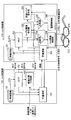
- FIG. 3 illustrates a configuration example of the shutter control unit 130 included in the display device 100 and the shutter control unit 210 included in the shutter glasses 200.
- the configuration of the shutter control units 130 and 210 will be described with reference to FIG.
- the shutter control unit 130 includes an oscillation circuit 131, a counter 132, a vertical synchronization latch circuit 133, and an RF communication unit 134.
- the shutter control unit 210 compares the oscillation circuit 231, the counter 232, the shutter switching value holding unit 233, the RF communication unit 234, the comparison unit 235, the shutter opening / closing control unit 236, and the transmission timing holding unit 243. Part 245 and a power supply control part 246.
- the oscillation circuit 131 is a circuit that oscillates at a predetermined frequency including a crystal resonator, and supplies the generated clock to the counter 132 as a reference clock Clk.
- the counter 132 is a counter that increases the value based on the reference clock Clk generated by the oscillation circuit 131 and outputs the value as the reference count value Cnt.
- the counter 132 is a counter used for instructing the opening / closing timing of the right-eye image transmission unit 212 and the left-eye image transmission unit 214 of the shutter glasses 200, and the display device 100 and the shutter are set to have the same value as the counter 232. It is controlled between the glasses 200. Further, the counter 132 is also used to inform the shutter glasses 200 of the transmission timing when the display device 100 transmits information to the shutter glasses 200, as will be described later.
- the vertical synchronization latch circuit 133 is a circuit that holds the value of the counter 132 at the rising and falling timings of the vertical synchronization pulse (reference sync signal Sync) supplied from the outside of the shutter control unit 130.
- the value of the counter 132 held by the vertical synchronization latch circuit 133 is wirelessly transmitted from the RF communication unit 134 to the shutter glasses 200 and stored in the shutter control unit 210.
- the RF communication unit 134 performs wireless communication with the RF communication unit 234 of the shutter control unit 210 based on IEEE802.15.4.
- the shutter control unit 210 transmits a clock frequency synchronization request to the display device 100, receives a packet wirelessly transmitted from the display device 100, synchronizes the clock frequency, and controls the opening / closing timing of the liquid crystal shutter. It is something to do.
- the RF communication unit 234 performs wireless communication with the RF communication unit 134 of the shutter control unit 130 based on IEEE802.15.4.
- the oscillation circuit 231 is a circuit that includes a crystal resonator and oscillates at a predetermined frequency, and supplies the generated clock to the counter 232 as a sub clock SubClk.
- the counter 232 is a counter that increases the value based on the sub clock SubClk generated by the oscillation circuit 231 and outputs the value as a sub count value Csub.
- the counter 232 is a counter used for switching between opening and closing of the right-eye image transmission unit 212 and the left-eye image transmission unit 214 of the shutter glasses 200, and compares the value of the counter 232 with the value held by the shutter switching value holding unit 233. This is because the shutter opening / closing control unit 236 controls to open and close the right-eye image transmission unit 212 and the left-eye image transmission unit 214 when they are compared with each other. In addition, the counter 232 compares the value of the counter 232 with the value held by the transmission timing holding unit 243 by the comparison unit 245, and controls the RF communication unit 234 so that reception is possible when they match. Also used for. Note that the bit length of the counter 232 is the same as the bit length of the counter 132.
- the shutter switching value holding unit 233 holds counter value information that is wirelessly transmitted from the display device 100 via the RF communication unit 134 and that specifies shutter opening / closing timing.
- the shutter opening / closing control unit 236 performs the right-eye image transmission unit 212 and the left-eye image transmission unit 212. Control is performed to open and close the image transmission unit 214.
- the comparison unit 235 compares the value of the counter 232 that is increased by the clock generated by the oscillation circuit 231 with the value stored in the shutter switching value holding unit 233. If the two values match, the comparison unit 235 instructs the shutter opening / closing control unit 236 to open / close the right-eye image transmission unit 212 and the left-eye image transmission unit 214 (right-eye control signal CTRLLR). And the left eye control signal CTRLL), and instructs the shutter switching value holding unit 233 to increase the value stored in the shutter switching value holding unit 233 in order to set the next opening / closing timing. .
- the increasing value is transmitted from the display device 100 to the shutter glasses 200 in advance as a switching cycle.
- the next opening / closing timing can be obtained by calculation in the shutter glasses 200 by transmitting the opening / closing cycle and opening / closing timing of the liquid crystal shutter as parameters to be described later from the display device 100 to the shutter glasses 200.
- the shutter switching value holding unit 233 holds the value obtained by calculation and holds the value while correcting the timing using the counter value transmitted from the shutter control unit 130 at a predetermined cycle. Then, the switching timing of the liquid crystal shutter is notified to the comparison unit 235 as a counter value held by the shutter switching value holding unit 233.
- the shutter opening / closing control unit 236 opens and closes the right-eye image transmission unit 212 and the left-eye image transmission unit 214, and is based on opening / closing instructions (right-eye control signal CTRLLR and left-eye control signal CTRLL) from the comparison unit 235.
- the right-eye image transmission unit 212 and the left-eye image transmission unit 214 are opened and closed.
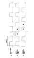
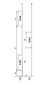
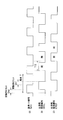
- FIG. 4 shows the relationship between the reference sync signal Sync and the right-eye control signal CTRLLR and the left-eye control signal CTRLL.
- FIG. 4A shows the waveform of the reference sync signal Sync
- FIG. 4B shows the left-eye control.
- the waveform of the signal CTRLL is shown
- (C) shows the waveform of the right eye control signal CTRLLR.
- the reference sync signal Sync has a rectangular waveform as shown in FIG.
- the duty ratio of the reference sync signal Sync can be changed.
- the left eye control signal CTRLL has the same waveform as the reference sync signal Sync.
- the video display system 10 operates so that the rising and falling timings of the reference sync signal Sync in the display device 100 are reproduced as the left eye control signal CTRLL in the shutter glasses 200.
- the right eye control signal CTRLLR is generated by the shutter opening / closing control unit 236 so as to have a waveform obtained by delaying the left eye control signal CTRLL by a half cycle.
- the left-eye control signal CTRLLL and the right-eye control signal CTRLR indicate the states of the left-eye image transmission unit 214 and the right-eye image transmission unit 212, respectively.
- the left-eye control signal CTRLL and the right-eye control signal CTRLLR indicate a transmission state (open state) at a high level and an interruption level (closed state) at an example level.
- the duty ratio of the reference sync signal Sync described above corresponds to the ratio between the transmission state and the cutoff state (opening / closing duty ratio) in each of the transmission parts of the left-eye image transmission part 214 and the right-eye image transmission part 212.
- the transmission timing holding unit 243 holds information on a counter value (transmission side count value Ctr described later) indicating transmission timing in the display device 100 that is wirelessly transmitted from the display device 100 via the RF communication unit 134. is there.
- the comparison unit 245 compares the value of the counter 232 with the value stored in the transmission timing holding unit 243. If the two values match, the comparison unit 245 instructs the power supply control unit 246 to enable reception of the RF communication unit 234, and sets the value stored in the transmission timing holding unit 243. Then, the transmission timing holding unit 243 is instructed to increase the value to set the next transmission timing.
- the increasing value is transmitted as a transmission timing cycle from the display device 100 to the shutter glasses 200 in advance.
- the next transmission timing can be obtained by calculation in the shutter glasses 200 by transmitting the transmission timing cycle and the transmission timing (transmission side count value Ctr) as parameters to be described later from the display device 100 to the shutter glasses 200. is there.
- the transmission timing holding unit 243 holds the value obtained by calculation, and holds the value while correcting the timing using the count value (transmission side count value Ctr) transmitted from the shutter control unit 130 at a predetermined period. Keep it. Then, the transmission timing is notified to the comparison unit 245 as a counter value held by the transmission timing holding unit 243.
- the power supply control unit 246 sets the state of the RF communication unit 234 to a receivable state or a low power consumption sleep state based on an instruction from the comparison unit 245. That is, the power supply control unit 246 sets a reception time slot based on an instruction from the comparison unit 245, and controls the RF communication unit 234 to be in a receivable state in accordance with the transmission timing of the display device 100. is there. Note that when the RF communication unit 234 is set to a dormant state, the power supply control unit 246 pauses circuits that do not interfere with the operation of the shutter glasses 200 except for the circuits such as the oscillation circuit 231 and the counter 232 that always require operation. You may make it be in a state.
- the display device 100 wirelessly transmits an opening / closing instruction for the right-eye image transmission unit 212 and the left-eye image transmission unit 214 to the shutter glasses 200 at a very short interval. There is no need. That is, the display device 100 holds the value of the counter 232 that is self-propelled therein and the shutter switching value even if the shutter glasses 200 do not give an instruction to open and close the shutter glasses 200 each time the shutter glasses 200 open and close the shutter.
- the right-eye image transmission unit 212 and the left-eye image transmission unit 214 can be controlled to open and close by comparison with the values held in the unit 233. That is, the display device 100 can wirelessly transmit an opening / closing instruction to the shutter glasses 200 at a period longer than the opening / closing period of the shutter.
- a reception time slot can be set in accordance with the transmission timing from the display device 100, and the RF communication unit 234 can be set in a receivable state. Thereby, the power consumption of the shutter glasses 200 can be reduced.
- the configuration of the shutter control units 130 and 210 has been described above with reference to FIG.
- the clock frequencies of the shutter control units 130 and 210 are used. Must match. Therefore, the shutter glasses 200 execute a process for matching the clock frequencies of the shutter control units 130 and 210 before performing the opening / closing operation of the right-eye image transmission unit 212 and the left-eye image transmission unit 214.
- a configuration for executing processing for matching the clock frequencies of the shutter control units 130 and 210 will be described.
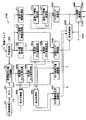
- FIG. 5 shows a configuration example of the shutter control units 130 and 210.
- FIG. 5 shows a configuration for executing processing for matching the clock frequencies of the shutter control units 130 and 210.
- the configuration of the shutter control units 130 and 210 will be described with reference to FIG.
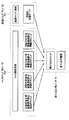
- the shutter control unit 130 includes an oscillation circuit 131 including a crystal resonator, an RF communication unit 134, a counter 161, a count value latch circuit 162, a timing generation interval control unit 163, A transmission timing generation unit 164 and a packet generation unit 165 are included.
- the shutter control unit 210 includes an oscillation circuit 231, an RF communication unit 234, a counter 261, a reception side count value latch circuit 262, a count value acquisition unit 263, reception side count value holding units 264a and 264b, and a transmission.
- the side count value holding units 265a and 265b, the difference acquisition units 266a and 266b, and the clock frequency control unit 267 are configured.
- the counter 161 is a counter for matching the clock frequencies of the shutter control units 130 and 210, and increases the value based on the reference clock Clk generated by the oscillation circuit 131 and outputs it as the reference count value Cnt.
- the count value latch circuit 162 latches the value of the counter 161 as the transmission-side count value Ctr, and the latch timing is the timing when the latch transmission trigger from the transmission timing generation unit 164 is received.
- the timing generation interval control unit 163 controls the interval of packet transmission timing from the RF communication unit 134.
- the timing generation interval control unit 163 notifies the transmission timing generation unit 164 that it is a packet transmission timing, for example, at intervals of several hundred milliseconds.
- the timing generation interval control unit 163 starts notification to the transmission timing generation unit 164.
- the transmission timing generation unit 164 notifies the packet generation unit 165 of the packet transmission timing. Upon receiving the notification from the timing generation interval control unit 163, the transmission timing generation unit 164 transmits a latch transmission trigger to the count value latch circuit 162, and the count value latch circuit 162 latches to the packet generation unit 165. The generation of a packet including the information of the counted value (transmitting side count value Ctr) is instructed.
- the packet generation unit 165 generates a packet including information on the count value (transmission side count value Ctr) latched by the count value latch circuit 162.
- the packet generated by the packet generation unit 165 is wirelessly transmitted from the RF communication unit 134.
- the display device 100 generates and transmits a packet including the count value information latched by the count value latch circuit 162 at the timing indicated by the timing generation interval control unit 163. That is, the count value (transmission-side count value Ctr) latched by the count value latch circuit 162 functions as a transmission time in the display device 100 when the display device 100 transmits a packet.
- the counter 261 is a counter for matching the clock frequencies of the shutter control units 130 and 210, and increases the value based on the sub clock SubClk generated by the oscillation circuit 231 and outputs it as a sub count value Csub.
- the reception-side count value latch circuit 262 latches the value of the counter 261, and the RF communication unit 234 receives a packet including information on the count value (transmission-side count value Ctr) latched by the count value latch circuit 162. At the received timing, the value of the counter 261 is latched. That is, the value of the counter 261 latched by the reception side count value latch circuit 262 (reception side count value Crec) functions as a reception time in the shutter glasses 200 when the shutter glasses 200 receive a packet.
- the value of the counter 261 latched by the reception side count value latch circuit 262 is sent to the reception side count value holding unit 264a. At the timing when the value of the counter 261 latched by the reception side count value latch circuit 262 is sent to the reception side count value holding unit 264a, the value held by the reception side count value holding unit 264a until then is received. It is sent to the side count value holding unit 264b.
- the count value acquisition unit 263 acquires information on the count value latched by the count value latch circuit 162 included in the packet received by the RF communication unit 234. The information on the count value acquired by the count value acquisition unit 263 is sent to the transmission side count value holding unit 265a.
- the receiving side count value holding units 264a and 264b hold the value of the counter 261 latched by the receiving side count value latch circuit 262.
- the reception-side count value holding unit 264a is latched by the reception-side count value latch circuit 262 at the timing when the packet containing the count value information latched by the count value latch circuit 162 transmitted from the RF communication unit 134 is received. It holds the value of the counter 261. Further, the reception-side count value holding unit 264b receives the reception-side count value latch at the timing of receiving the packet that includes the count value information latched by the count value latch circuit 162 that was previously transmitted from the RF communication unit 134. The value of the counter 261 latched by the circuit 262 is held.
- the transmission-side count value holding units 265a and 265b hold the count value acquired by the count value acquisition unit 263 and latched by the count value latch circuit 162.
- the transmission side count value holding unit 265a holds the count value (transmission side count value Ctr) latched by the count value latch circuit 162 included in the packet transmitted from the RF communication unit 134.
- the transmission side count value holding unit 265b holds the count value latched by the count value latch circuit 162 included in the packet transmitted from the RF communication unit 134 last time.
- the difference acquisition unit 266a acquires a difference between values held by the reception-side count value holding units 264a and 264b.
- the difference acquisition unit 266b acquires a difference between values held by the transmission side count value holding units 265a and 265b.
- the clock frequency control unit 267 compares the differences acquired by the difference acquisition units 266a and 266b, grasps the difference in clock frequency between the transmission side and the reception side, and controls the clock frequency of the oscillation circuit 231. . That is, for example, if the difference of the counter 161 on the transmission side is larger than the difference of the counter 261 on the reception side, the clock frequency of the reference clock Clk generated by the oscillation circuit 131 is subclock SubClk generated by the oscillation circuit 231. Therefore, the clock frequency control unit 267 controls the clock frequency of the oscillation circuit 231 in a higher direction so as to match the clock frequency of the oscillation circuit 131.
- the clock frequency of the oscillation circuit 231 can be matched with the clock frequency of the oscillation circuit 131.
- the shutter control unit 210 may continuously perform the clock frequency control processing of the oscillation circuit 231 by the clock frequency control unit 267 a plurality of times.
- a packet for synchronizing the clock frequency (clock frequency synchronization packet) is periodically transmitted from the shutter control unit 130 even after the clock frequency of the oscillation circuit 231 is matched with the clock frequency of the oscillation circuit 131.
- the shutter glasses 200 can receive the clock frequency synchronization packet periodically transmitted from the shutter control unit 130, execute the clock frequency synchronization process, and continuously synchronize the clock frequency.
- the transmission cycle of the clock frequency synchronization packet from the shutter control unit 130 may be longer than the transmission cycle when the clock frequency is first synchronized.
- the display device 100 corresponds to a specific example of “video display device” in the present invention.
- the image display unit 110 corresponds to a specific example of “display unit” in the present invention.
- the counters 132 and 161 correspond to a specific example of “clock counter” in the video display device of the present invention.
- the transmission side count value Ctr corresponds to a specific example of “transmission time count value” in the present invention.
- the RF communication unit 134 corresponds to a specific example of “transmission unit” in the present invention.
- the right-eye image transmission unit 212 and the left-eye image transmission unit 214 correspond to a specific example of “shutter” in the present invention.
- the counters 232 and 261 correspond to a specific example of “clock counter” in the shutter glasses of the present invention.
- the reception-side count value Crec corresponds to a specific example of “reception time count value” in the present invention.
- the RF communication unit 234, the reception side count value latch circuit 262, the reception side count value holding units 264a and 264b, the count value acquisition unit 263, and the transmission side count value holding units 265a and 265b are one of the “reception units” in the present invention. This corresponds to a specific example.
- the power supply control unit 246 corresponds to a specific example of “control unit” in the present invention.
- FIG. 6 shows a series of operations between the display device 100 and the shutter glasses 200.
- a series of operations between the display device 100 and the shutter glasses 200 will be described with reference to FIG.
- the solid line represents unicast transmission
- the broken line represents broadcast transmission.
- the shutter glasses 200 wirelessly transmit a clock frequency synchronization request to the display device 100 (step S101).
- the clock frequency synchronization request packet is generated by, for example, the shutter control unit 210.
- Display device 100 that has wirelessly received the clock frequency synchronization request from shutter glasses 200 wirelessly transmits a packet including the value of counter 161 for clock frequency synchronization to shutter glasses 200 (step S102).
- the display device 100 broadcasts a packet including the value of the counter 161, which will be described in detail later.
- the shutter glasses 200 When the shutter glasses 200 synchronize the clock frequency with the display device 100, the shutter glasses 200 subsequently specify the opening / closing timing of the right-eye image transmission unit 212 and the left-eye image transmission unit 214 with respect to the display device 100.
- a request for matching the counter value of the counter 161 is wirelessly transmitted (step S103). It is desirable that the count value matching process between the display device 100 and the shutter glasses 200 is repeated a plurality of times until the counter values completely match in consideration of the time required for wireless communication and variations in time. When the value falls within the allowable range, the counter value matching process may be completed.
- the value of the counter 132 at the timing at which the video that is time-division-displayed on the display device 100 is subsequently switched from the display device 100 to the shutter glasses 200 is displayed as the right-eye image.
- broadcast transmission is periodically performed wirelessly (step S104).
- the notification of the opening / closing timing is transmitted at an interval (for example, an interval of several hundred milliseconds) sufficiently longer than the interval at which the display device 100 switches the video.
- a packet including the counter value of the counter 161 for synchronizing the clock frequency is periodically sent to the shutter glasses 200.
- Radio transmission is performed (step S105).
- the transmission of the packet including the counter value of the counter 161 is not performed periodically, but the switching timing of the video source, for example, the timing when the content changes (from the content displaying 3D video to the conventional 2D (Including the timing of changing to the content for displaying the video and vice versa) and the timing at which the channel is switched in the display device 100 may be broadcasted from the display device 100.
- the opening / closing timings of the right-eye image transmission unit 212 and the left-eye image transmission unit 214 of the shutter glasses 200 can be matched with the switching timing of the video displayed on the display device 100.
- the switching timing of the video displayed on the display device 100 may be shifted depending on factors such as switching of the video source. Therefore, the switching timing of the right-eye image transmission unit 212 and the left-eye image transmission unit 214 from the display device 100 is changed. It is desirable to perform transmission at a predetermined cycle as described above.
- various parameters relating to the opening / closing timing are wirelessly transmitted from the display device 100 in accordance with the transmission of the opening / closing timing in step S104.
- the vertical synchronization frequency at which the display device 100 displays an image is not one, but changes depending on the region and the production of the device.
- the opening / closing timing of the shutter glasses 200 also changes depending on the type of the display panel. Therefore, by transmitting various parameters related to the opening / closing timing from the display device 100 to the shutter glasses 200, the shutter glasses 200 can be made to correspond to various types of display devices.
- the open / close pattern of the liquid crystal shutter of the shutter glasses 200 when the image displayed on the image display unit 110 is perceived as a stereoscopic image is such that the right-eye image transmission unit 212 and the left-eye image transmission unit 214 open alternately. Yes, both will not open at the same time.
- both the liquid crystal shutters are closed for too long, the time for which the liquid crystal shutters are opened is shortened, and the amount of light reaching the eyes is reduced, so that the image appears dark.
- the opening / closing cycle of the liquid crystal shutter of the shutter glasses 200 is determined by the frame cycle of the display device 100 and the number of times of image replacement.
- the frame period of the display device 100 varies depending on the frame frequency of the video source and the presence / absence of image quality improvement processing such as processing for improving the number of display frames executed by the display device 100.
- the time for closing both liquid crystal shutters to prevent crosstalk is affected by the number of times the video of the display device 100 is replaced, and the device type of the display panel (CRT, liquid crystal, LED liquid crystal, plasma, organic EL, etc.) The optimum value changes depending on the scanning method of the display panel.
- the optimal value of the opening / closing timing of the liquid crystal shutter of the shutter glasses 200 is not determined by the shutter glasses 200, but is determined by the production of the display device 100 and the video source.
- the optimal value of the opening / closing timing of the liquid crystal shutter of the shutter glasses 200 is not determined by the shutter glasses 200, but is determined by the production of the display device 100 and the video source.
- a planar video is displayed on the display device 100, the video is easy to see. In order to do this, it is desirable to stop the opening / closing operation of the liquid crystal shutter of the shutter glasses 200 and keep it open at all times.
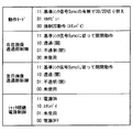
- the display device 100 notifies the shutter glasses 200 of the timing for opening and closing the liquid crystal shutter of the shutter glasses 200 as a parameter, so that the liquid crystal shutter opening and closing timing of the shutter glasses 200 is determined. It can be easily optimized. Specifically, the display device 100 transmits, to the shutter glasses 200 as parameters, an opening / closing cycle of the liquid crystal shutter, an image transmission time of the liquid crystal shutter, and an offset time until the start of the image transmission time of the left and right liquid crystal shutters. Thus, the opening / closing timing of the liquid crystal shutter of the shutter glasses 200 can be optimized.
- FIG. 7 shows an example of the opening / closing timings of the right-eye image transmission unit 212 and the left-eye image transmission unit 214.
- (1) represents the opening / closing cycle of the liquid crystal shutter, which coincides with the switching cycle of the video displayed on the display device 100.
- (2) represents the video transmission time of the liquid crystal shutter, and is the time for the right eye image transmission unit 212 and the left eye image transmission unit 214 of the shutter glasses 200 to transmit light during one cycle.
- the video transmission time is the same for the right eye and the left eye, and the video transmission time is determined by the type of the display device 100 and the frame frequency.
- (3) and (4) are offset times from the starting point of the liquid crystal shutter opening / closing cycle until the left and right liquid crystal shutters are opened.
- the parameters (1) to (4) transmitted from the display device 100 are based on the value of the counter 132 (counter 232).
- the clock frequency of the display device 100 and the shutter glasses 200 and the values of the counters 132 and 232 are synchronized.
- the opening / closing timing of the liquid crystal shutter of the shutter glasses 200 can be controlled from the display device 100.
- FIG. 7 shows an example of the opening / closing timing when the user wearing the shutter glasses 200 perceives a stereoscopic image.
- the right eye is used.
- the image transmission unit 212 and the left-eye image transmission unit 214 open and close at the same time, and when a planar image is presented, the right-eye image transmission unit 212 and the left-eye image transmission unit 214 are always open. Accordingly, the display device 100 transmits the type of video to be displayed to the shutter glasses 200 as a parameter, so that the shutter glasses 200 can control the opening / closing timing of the liquid crystal shutter.
- the display device 100 wirelessly transmits to the shutter glasses 200 the timing (transmission side count value Ctr) for transmitting information related to the opening / closing timing using the above parameters.
- the shutter glasses 200 can suppress power consumption by switching on / off of the reception operation at this timing.
- the clock frequency is synchronized between the display device 100 and the shutter glasses 200 in advance, and the display device 100 periodically notifies the opening / closing timing of the right-eye image transmission unit 212 and the left-eye image transmission unit 214.
- the RF communication unit 234 only needs to be operated at the timing when the opening / closing timing is notified, and the display device 100 is greatly compared with the case where the opening / closing timing is notified simultaneously with the video switching timing from the display device 100.
- the power consumption of the shutter glasses 200 can be reduced. Further, by notifying the opening / closing timing information from the display device 100 in advance, even if the shutter glasses 200 cannot receive a packet from the display device 100 for some reason, the shutter glasses 200 are self-propelled. Based on the counter 232, the opening / closing operation of the right-eye image transmission unit 212 and the left-eye image transmission unit 214 can be continued.
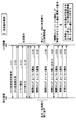
- Packets wirelessly transmitted and received between the display device 100 and the shutter glasses 200 include (1) a clock frequency synchronization request packet, (2) a clock frequency synchronization packet, (3) a counter adjustment packet, (4) a parameter notification packet, (5) A shutter timing notification packet and (6) a shutter timing and a parameter inquiry packet are included.
- the clock frequency synchronization request packet is a packet transmitted from the shutter glasses 200 to the display device 100.
- the display device 100 receives the clock frequency synchronization request packet, the value of the counter 161 used for clock frequency synchronization is received. It returns to the shutter glasses 200 a plurality of times by (2) a clock frequency synchronization packet.
- the clock frequency synchronization packet is, as described above, (1) the display device that has received the clock frequency synchronization request packet sets the value of the counter 161 used for clock frequency synchronization to the shutter glasses 200 a plurality of times. Packet to be transmitted.
- the counter matching packet is a packet that is wirelessly transmitted and received between the display device 100 and the shutter glasses 200, and is transmitted from the shutter glasses 200 with the clock frequency synchronized with the display device 100.
- the value of the counter 132 is returned from the display device 100 and used for counter adjustment with the shutter glasses 200.
- the parameter notification packet transmits various parameters relating to the opening / closing timing of the liquid crystal shutter of the shutter glasses 200 as described above, the transmission timing (transmission side count value Ctr) from the display device 100, and the transmission timing cycle from the display device 100. (2) It may be transmitted at the same timing as the transmission of the clock frequency synchronization packet.
- the shutter timing notification packet is a packet that is periodically broadcast from the display device 100 to the shutter glasses 200, and is a packet for notifying the opening / closing timing of the liquid crystal shutter of the shutter glasses 200 by a counter value. is there.
- the shutter timing and parameter inquiry packet is a packet for individually requesting transmission of the shutter timing notification packet when the shutter glasses 200 cannot receive the (5) shutter timing notification packet from the display device 100. Note that (6) the response from the display device 100 that has received the shutter timing and parameter inquiry packet is sent by unicast.
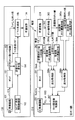
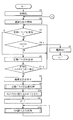
- FIG. 8 shows an operation example of the video display system 10 using a flowchart.
- a series of operations between the display device 100 and the shutter glasses 200 will be described with reference to FIG.
- the shutter glasses 200 wirelessly transmit a clock frequency synchronization request to the display device 100 (step S111).
- the clock frequency synchronization request packet is generated by, for example, the shutter control unit 210.
- the timing when the synchronization request from the shutter glasses 200 is transmitted is, for example, the timing when the power of the shutter glasses 200 is turned on.
- the display device 100 that wirelessly receives the clock frequency synchronization request from the shutter glasses 200 wirelessly transmits a packet including the counter value of the counter 161 for clock frequency synchronization to the shutter glasses 200.
- the shutter glasses 200 having received the packet including the counter value of the counter 161 wirelessly transmitted from the display device 100 executes a process of matching the clock frequencies of the display device 100 and the shutter glasses 200 (step S112).
- the process of matching the clock frequencies of the display device 100 and the shutter glasses 200 is executed with the configuration shown in FIG. 3, but in the present invention, the process of matching the clock frequencies of the display device 100 and the shutter glasses 200 is executed. Is not limited to such an example.
- the counter values used for opening and closing the right-eye image transmission unit 212 and the left-eye image transmission unit 214 are made to match between the display device 100 and the shutter glasses 200 (step). S113). This is because the shutter glasses 200 wirelessly transmit a counter value match request for designating the opening / closing timing of the right-eye image transmission unit 212 and the left-eye image transmission unit 214 to the display device 100. This is executed by wirelessly transmitting counter value information to the shutter glasses 200 in response to a value matching request.
- the display device 100 When the counter values used to open and close the right-eye image transmission unit 212 and the left-eye image transmission unit 214 are matched between the display device 100 and the shutter glasses 200, the display device 100 then displays the right-eye image with respect to the shutter glasses 200. Parameters such as the switching period and opening time of the transmission unit 212 and the left-eye image transmission unit 214 are notified (step S114), and based on counter values used for opening and closing the right-eye image transmission unit 212 and the left-eye image transmission unit 214 The opened / closed timing is notified (step S115). This parameter may be transmitted from the display device 100 to the shutter glasses 200 when the clock frequencies of the display device 100 and the shutter glasses 200 match. Further, when notifying the opening / closing timing, the display device 100 notifies the shutter glasses 200 of the current counter value, and the shutter glasses 200 compare the received counter value with its own counter value, and the synchronization is not lost. Whether or not (step S116).
- step S116 determines whether synchronization between the display device 100 and the shutter glasses 200 has been maintained. If the result of determination in step S116 is that synchronization between the display device 100 and the shutter glasses 200 has been maintained, the state of the shutter glasses 200 waits for the next synchronization confirmation timing (step S117). On the other hand, if the display device 100 and the shutter glasses 200 are out of synchronization as a result of the determination in step S116, the process returns to step S111, and the shutter glasses 200 synchronize the clock frequency with the display device 100. Send the request over the air.
- transmission is performed by first transmitting the opening / closing timing from the display device 100 to the shutter glasses 200. If the counter is advanced with the respective clocks of the reception side and the reception side and the liquid crystal shutter opening / closing operation can be executed based on the value of the counter, the display device 100 periodically broadcasts the opening / closing timing as described above. There is no need to send.
- the switching timing of the video displayed on the display device 100 changes due to switching of the channel or the content to be played back, it is also necessary to change the shutter opening / closing timing of the shutter glasses 200. .
- the change in the switching timing that occurs for this reason cannot be expected by the shutter glasses 200. Therefore, the display device 100 needs to notify the shutter glasses 200 of the opening / closing timing.
- the shutter glasses 200 are always in the reception state, power for reception is always consumed, and the battery driving time of the shutter glasses 200, which is premised on battery driving, cannot be increased.
- the shutter glasses 200 synchronize the clock frequencies, match the counter values, and after receiving the parameters and switching timing related to switching for the first time from the display device 100, set the reception time slot and intermittently execute the receiving operation. To do. Thereby, the shutter glasses 200 can significantly reduce the power during reception, and the battery driving time of the shutter glasses 200 can be extended.
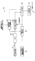
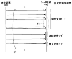
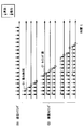
- FIG. 9 shows an example of a communication operation in the video display system 10 as a sequence diagram.
- FIG. 9 also illustrates a reception operation period of the RF communication unit 234 in the shutter glasses 200 together with a series of operations between the display device 100 and the shutter glasses 200.
- a series of operations between the display device 100 and the shutter glasses 200 will be described with reference to FIG.
- the shutter glasses 200 wirelessly transmit a clock frequency synchronization request to the display device 100 (step S121).
- the clock frequency synchronization request packet is generated by, for example, the shutter control unit 210.
- the timing when the synchronization request from the shutter glasses 200 is transmitted is, for example, the timing when the power of the shutter glasses 200 is turned on.
- the display device 100 that wirelessly receives the clock frequency synchronization request from the shutter glasses 200 wirelessly transmits a packet including a counter value for clock frequency synchronization to the shutter glasses 200.
- the shutter glasses 200 that have received the packet execute processing for matching the clock frequencies of the display device 100 and the shutter glasses 200 (step S122).
- Step S124 relates to various parameters relating to the opening / closing of the right-eye image transmission unit 212 and the left-eye image transmission unit 214 from the display device 100 to the shutter glasses 200 and transmission from the display device 100 prior to the counter value matching process.
- Various parameters may be transmitted (step S123).
- the display device 100 When the counter values used to open and close the right-eye image transmission unit 212 and the left-eye image transmission unit 214 are matched between the display device 100 and the shutter glasses 200, the display device 100 then displays the right-eye image with respect to the shutter glasses 200. In addition to notifying parameters such as the switching period and opening time of the transmission unit 212 and the left-eye image transmission unit 214, the opening / closing timing based on the counter values used for opening and closing the right-eye image transmission unit 212 and the left-eye image transmission unit 214 is provided. Notification is made (step S125). At the same time, the display device 100 transmits the transmission timing period and the transmission timing (transmission side count value Ctr) as parameters. The display device 100 wirelessly transmits parameters and opening / closing timing information at preset intervals after the initial notification.
- the shutter glasses 200 use the period from the wireless transmission of the clock frequency synchronization request in step S121 to the initial notification from the display device 100 as the reception operation period in the RF communication unit 234, and thereafter parameters from the display device 100.
- the RF communication unit 234 is operated for reception for a predetermined time (reception time slot), and the rest of the time is set to the resting state. For example, when parameters and opening / closing timing information are wirelessly transmitted from the display device 100 at intervals of 500 milliseconds, the shutter glasses 200 transmit the RF communication unit 234 for 5 milliseconds according to the wireless transmission timing from the display device 100. Start receiving.
- the reception time slot is set by the transmission timing holding unit 243, the comparison unit 245, and the power supply control unit 246 based on various parameters related to transmission supplied from the display device 100.
- the wireless communication system used in this embodiment is based on IEEE802.15.4, and in IEEE802.15.4, the time required for transmission from the sleep state or the time required for reception from the sleep state is about several milliseconds. Is possible.
- the shutter glasses 200 can significantly reduce the power consumption required for wireless communication to about 1/100 compared to the case where the shutter glasses 200 are always in the reception state.
- the standard of the wireless communication system between the display device 100 and the shutter glasses 200 is not limited to such an example.
- it is desirable to use a standard in which the time required from reception to hibernation is about several milliseconds or less.
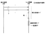
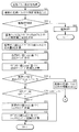
- the shutter glasses 200 cannot normally receive the parameter and the opening / closing timing information from the display device 100 due to the presence of a shielding object, out-of-synchronization, and the like, the parameters and the opening / closing timing of the display device 100 are displayed.
- Information is inquired (step S126). In this case, when the signal cannot be normally received once, the display may be immediately inquired to the display device 100 from the shutter glasses 200. When the signal cannot be normally received several times continuously, the display from the shutter glasses 200 to the display device 100 may be performed. You may be made to contact.
- the display device 100 wirelessly transmits parameters and opening / closing timing information to the shutter glasses 200.
- the shutter glasses 200 determine that the synchronization is out of sync and the shutter glasses 200 display the display device.
- a clock frequency synchronization request is wirelessly transmitted to 100 again, and a series of processing is executed from the beginning. If there is no response from the display device 100 even when a clock frequency synchronization request is wirelessly transmitted from the shutter glasses 200 to the display device 100 again, it is determined that the display device 100 has been turned off, and the shutter is released.
- the glasses 200 can shift themselves to a sleep state that consumes little power.
- the clock frequency is at a timing that does not affect the other shutter glasses 200.
- the value of the counter 161 used for the synchronization process is wirelessly transmitted by unicast to the shutter glasses 200 that transmitted the synchronization request.
- the display device 100 transmits the signal at a predetermined cycle immediately before the start of reception from the shutter glasses 200 without periodically reporting the parameters and the opening / closing timing information, and receives the signal from the shutter glasses 200.
- 100 notifies the parameter and opening / closing timing information at the received timing, thereby increasing the time required for transmission of the shutter glasses 200 and the response time of the display device 100, but the operation similar to the above operation is strict. This can be achieved without the need for timing management.
- the clock frequency is synchronized between the display device 100 and the shutter glasses 200 in advance, and the counters of the display device 100 and the shutter glasses 200 are made to coincide with each other, and then periodically from the display device 100.
- the amount of radio waves does not increase and the shutter glasses 200 do not collide with each other.
- other wireless communications using the same frequency band need not be affected.
- a remote controller using infrared light has a reach distance of about 10 m. This is not just light on / off, but also a carrier of about 40 kHz by changing the intensity of light. Above, the light on this carrier is turned on / off.
- the receiving side is provided with a circuit that resonates with the frequency of the carrier, thereby greatly improving the sensitivity and achieving such a reachable distance.
- the remote controller code may have a communication speed such that one code is transmitted every 100 milliseconds.
- shutter glasses that switch images at intervals of about 10 to 20 milliseconds have a switching interval of images. Since this is the shutter switching interval, it is necessary to send the code at a rate of once every 10 milliseconds to 20 milliseconds. Therefore, even if a carrier is placed, the transmission time is short and the carrier cannot be sufficiently resonated. As a result, it is not possible to achieve an improvement in sensitivity as in a remote controller.
- a resonance circuit when a resonance circuit is used on the receiving side, a delay occurs, and the amount of delay varies due to the influence of the Q value of the resonance circuit, so that accurate shutter switching timing cannot be transmitted from the display device.
- a resonance circuit when a resonance circuit is used on the receiving side, power consumption increases, and in shutter glasses that are premised on battery driving, the battery is consumed in a short time.
- the side that transmits infrared light makes the light stronger by arranging a plurality of infrared LEDs, or an expensive LED that emits a large amount of light is used, and the receiver side is an expensive photo that is as sensitive as possible. At present, there is no other way but to use a diode.
- the reach distance can be extended from the infrared light with less power.
- a large amount of information can be sent in a short time, and reliable transmission and separation are possible by designating a partner.
- the radio waves are not affected and bidirectional communication can be easily performed, so that the usability can be improved.
- it can be used at a low cost, and there is also an advantage that infrared light such as existing remote controllers that are widely used does not interfere with equipment used for communication. .
- the wireless communication system used in the present embodiment is based on IEEE 802.15.4, and the wireless communication system based on IEEE 802.15.4 has the following characteristics compared to other wireless communication standards.
- a star network can be configured.
- the number of peripheral nodes for a single center node is practically unlimited. Therefore, it is possible to eliminate the restriction on the number of shutter glasses for one display device.
- the wireless communication system used in the video display system synchronizes the clock frequency of the peripheral node (i.e., shutter glasses 200) with the clock frequency of the center node (i.e., display device 100) in IEEE 802.15.4. It is based on what added the function.
- the display device 100 in the video display system in which the opening / closing timing of the liquid crystal shutter of the shutter glasses 200 is transmitted wirelessly from the display device 100, before the display device 100 notifies the opening / closing timing, the display device 100.
- the shutter glasses 200 wirelessly transmit a clock frequency synchronization request to the display device 100.
- the shutter glasses 200 can self-run the opening / closing operation of the liquid crystal shutter without transmitting a timing signal or the like from the display device 100 in accordance with the opening / closing timing of the liquid crystal shutter.
- the display device 100 periodically notifies the shutter glasses 200 of the opening / closing timing of the liquid crystal shutter and various parameters, and the shutter glasses 200 adjust the RF communication unit in accordance with the transmission cycle of the display device 100.
- 234 is in a receivable state for a predetermined period, and in other periods, the RF communication unit 234 is in a sleep state in which little power is consumed. Thereby, the power consumption of the shutter glasses 200 can be significantly reduced as compared with the case where the RF communication unit 234 is always in a receivable state.
- the shutter glasses 200 are separately provided with a means for measuring an angle and angular velocity like a gyroscope. Thus, it is possible to display on the display device 100 an image that matches the viewpoint of the user who views the image displayed on the display device 100 through the shutter glasses 200.
- the counter glasses are inquired of the display device 100 for the value of the counter, and the display device 100 that received the inquiry receives the shutter glasses 200.
- the display device 100 may transmit a packet in which the value of the counter 132 at the time of transmitting the clock frequency synchronization packet is embedded at the same timing as the transmission of the clock frequency synchronization packet to the shutter glasses 200.
- the shutter glasses 200 When receiving the packet, the shutter glasses 200 have a constant delay time (for example, a time required for packet generation and decoding, packet transmission / reception time, etc.) that occurs until the received counter value is written in the counter 232.
- the counter value is written in the counter 232 in consideration of the delay time, so that the counter value used for opening and closing the liquid crystal shutter can be obtained from the display device 100 and the shutter glasses 200 without inquiring from the shutter glasses 200 as described above. Can be matched with.
- the video display system 20 according to the second embodiment of the present invention will be described.
- This embodiment is different from the first embodiment in the method for obtaining the transmission timing from the display device in the shutter glasses. That is, in the first embodiment (FIG. 5), the value of the counter 261 (subcount value Csub) of the shutter glasses 200 is made to coincide with the value of the counter 161 (reference count value Cnt) of the display device 100.
- the shutter glasses 200 obtain the transmission timing from the display device 100. Instead, in this embodiment, the shutter glasses 200 obtain the transmission timing based on the relationship between the subcount value Csub and the reference count value Cnt. is there.
- the configuration of the video display system 20 is the same as that of the video display system 10 according to the first embodiment shown in FIG. 1, except that the shutter control unit of the display device and the shutter control unit of the shutter glasses are the above-described first. This is different from the embodiment.
- symbol is attached
- FIG. 10 illustrates a configuration example of the shutter control unit 310 of the display device 300 according to the video display system 20.
- FIG. 11 illustrates a configuration example of the shutter control unit 410 of the shutter glasses 400 according to the video display system 20.
- the shutter control unit 310 of the display device 300 includes a vertical synchronization latch circuit 133 and a packet generation unit 365.
- the vertical synchronization latch circuit 133 is the same as the vertical synchronization latch circuit 133 shown in FIG. 3, and the value of the counter 161 at the rising and falling timings of the reference sync signal Sync supplied from the outside of the shutter control unit 130 is obtained. It is a circuit to hold.
- the packet generator 365 generates a packet including information on the reference sync signal Sync and other control information in addition to the information on the count value (transmission side count value Ctr) latched by the count value latch circuit 162. is there.
- the display device 300 periodically transmits a packet (periodic packet P).
- the regular packet P will be described in detail.
- FIG. 12 shows a configuration example of the regular packet P transmitted by the display device 300.
- the regular packet P is composed of synchronization information A and control information B.
- the synchronization information A is information necessary for the display device 300 and the shutter glasses 400 to synchronize, and is composed of real-time synchronization information A1 and reference sync information A2.
- FIG. 13A to 13C show one configuration example of the synchronization information A.
- FIG. 13A shows the relationship between the synchronization information A, the real-time synchronization information A1, and the reference sync information A2, and FIG. 13B shows each of the synchronization information A. The parameters are shown, and FIG. 13C shows waveforms that illustrate some of the parameters.
- the real-time synchronization information A1 includes two parameters of count values RC and RP
- the reference sync information A2 includes count values Srise, Sfall, pulse number Snum, and flag Sf1. , Sf2 and Sf3, a total of six parameters.
- the count value RC is a reference count value Cnt when the regular packet P is transmitted, and is a count value (transmission side count value Ctr) latched by the count value latch circuit 162. This RC functions as a transmission time in the display device 300 when the display device 300 transmits the regular packet P.
- the count value RP is a transmission timing period of the regular packet P, and is a value based on the reference count value Cnt. In other words, RP is a count value by the reference clock Clk of the transmission timing period of the regular packet P.
- the count value Srise is the reference count value Cnt when the reference sync signal Sync rises
- the count value Sfall is the reference count value Cnt when the reference sync signal Sync falls.
- the pulse number Snum is the pulse number of the reference sync signal Sync, and is incremented by one every time the reference sync signal Sync becomes high level.
- FIG. 13C shows these count values Srise, Sfall, Snum together with the waveforms of the reference sync signal Sync and the reference clock signal Clk.
- the flag Sf1 is a disturbance flag for the reference sync signal Sync. Specifically, Sf1 becomes active when the period T of the reference sync signal Sync is deviated by, for example, ⁇ 100 usec compared with the average value of the period T so far.
- the flag Sf1 may be activated continuously in a plurality (for example, three) of regular packets P after the reference sync signal Sync is disturbed. In this case, even if the shutter glasses 400 fail to receive the first regular packet P, the shutter glasses 400 can surely know that the reference sync signal Sync is disturbed by receiving the subsequent regular packet P.
- the flag Sf2 is a flag that becomes active when there is no reference sync signal Sync.
- the flag Sf3 is a flag that indicates the relationship between the count values Srise and Sfall. Specifically, for example, it is “1” when the count value Sfall is larger than the count value Srise, and “0” when the count value Sfall is smaller than the count value Srise.
- FIG. 14 shows a configuration example of the control information B.
- the control information B sets the operation mode, the right-eye image transmission unit control, the left-eye image transmission unit control, and the eyeglass power source control.
- the operation mode is a mode in which the operation of the shutter glasses 400 is automatically switched to 3D or 2D depending on the presence / absence of the reference sync signal Sync. It is possible to set the mode so that the user can view separate 2D video images, and in the case of “00”, the user can set the shutter glasses to the standby state and enter the mode for viewing 2D video images.
- the right-eye image transmission unit control and the left-eye image transmission unit control are in a mode in which an opening / closing operation is performed according to the reference sync signal Sync.
- the mode can be set so as to enter the non-transparent state (closed state).
- the power of the shutter glasses 400 is turned on, when “10”, the standby state is set, and when “00”, the power is turned off. Can be set.
- the packet generation unit 365 In the shutter control unit 310 of the display device 300, the packet generation unit 365 generates a regular packet P having the configuration as described above, and the RF communication unit 134 periodically broadcasts the regular packet P.
- the shutter controller 410 of the shutter glasses 400 includes a reception side count value holding unit 464a, 464b, a transmission side count value holding unit 465a, 465b, a difference acquisition unit 466a, 466b, a count value difference amount calculation unit 421, a clock Period correction amount calculation unit 422, reference sync information acquisition unit 411, reference sync information holding units 412a and 412b, transmission timing calculation unit 431, shutter timing calculation unit 432, count value conversion units 441 and 442, power supply A control unit 443 and a shutter opening / closing control unit 444 are provided.
- the reception side count value holding units 464a and 464b hold the value of the counter 261 (reception side count value Crec) latched by the reception side count value latch circuit 262 every predetermined number of times.
- the reception side count value Crec functions as the reception time of the regular packet P in the shutter glasses 400.
- the reception-side count value holding unit 464a reads and holds the reception-side count value Crec supplied from the reception-side count value latch circuit 262 at a rate of once every predetermined number of times. At this time, the information held in the reception-side count value holding unit 464a is transferred to the reception-side count value holding unit 464b at the same time that the reception-side count value holding unit 464a holds new information, and the reception-side count value holding unit 464b. It is supposed to be held at. That is, the reception side count value latch circuit 262 and the reception side count value holding units 464a and 464b have a function of holding a maximum of three reception times of the regular packet P.
- the transmission-side count value holding units 465a and 465b hold the count value (transmission-side count value Ctr) acquired by the count value acquisition unit 263 and latched by the count value latch circuit 162 of the display device 300 every predetermined number of times. It is.
- This transmission-side count value Ctr functions as the transmission time of the regular packet P in the display device 300.
- the transmission-side count value holding unit 465a reads and holds the transmission-side count value Ctr supplied from the count value acquisition unit 263 at a rate of once every predetermined number of times.
- the information held in the transmission side count value holding unit 465a is transferred to the transmission side count value holding unit 465b at the same time as the transmission side count value holding unit 465a holds new information, and the transmission side count value holding unit 465b. It is supposed to be held at. That is, the count value acquisition unit 263 and the transmission side count value holding units 465a and 465b have a function of holding a maximum of three transmission times of the regular packet P.
- the difference acquisition unit 466a obtains the difference based on two values of the count values held in the reception-side count value latch circuit 262 and the reception-side count value holding units 464a and 464b. As these two values, the count values held in the reception-side count value latch circuit 262 and the reception-side count value holding unit 464b are usually selected, but as will be described later, immediately after the shutter glasses 400 are activated, etc. When the count value is not held in the reception count value holding unit 464b because the shutter glasses 400 have not received the regular packet P three times, the reception side count value latch circuit 262 and the reception side count value holding unit The count value held at 464a is selected.
- the difference acquisition unit 466b calculates a difference based on two values of the count values held in the count value acquisition unit 263 and the transmission side count value holding units 465a and 465b. As these two values, the count values held in the count value acquisition unit 263 and the transmission side count value holding unit 465b are normally selected, as in the difference acquisition unit 466a described above. When the count value is not held in the holding unit 465b, the count value held in the count value acquisition unit 263 and the transmission side count value holding unit 465a is selected.
- the count value difference amount calculation unit 421 obtains the difference between the reference count value Cnt of the display device 300 and the sub count value Csub of the shutter glasses 400 based on the transmission side count value Ctr and the reception side count value Crec, and the difference amount D Is output as Specifically, the count value difference amount calculation unit 421 performs a calculation based on the count values latched by the reception side count value latch circuit 262 and the count value acquisition unit 263.
- the clock cycle correction amount calculation unit 422 calculates the ratio of the cycle between the reference clock Clk of the display device 300 and the sub clock SubClk of the shutter glasses 400 and outputs the ratio as the clock cycle correction amount R. Specifically, the clock cycle correction amount calculation unit 422 performs a calculation based on information supplied from the difference acquisition units 466a and 466b.
- the reference sync information acquisition unit 411 acquires the reference sync information A2 (FIG. 13A) included in the regular packet P received by the RF communication unit 234.
- the reference sync information holding units 412a and 412b hold the reference sync information A2 acquired by the reference sync information acquisition unit 411 every predetermined number of times.
- the reference sync information holding unit 412a reads and holds the reference sync information A2 supplied from the reference sync information acquisition unit 411 at a rate of once every predetermined number of times.
- the information held in the reference sync information holding unit 412a is transferred to the reference sync information holding unit 412b at the same time that the reference sync information holding unit 412a holds new information, and is held in the reference sync information holding unit 412b. It is like that. That is, the reference sync information acquisition unit 411 has a function of holding a maximum of three reference sync information A2.
- the packet transmission interval acquisition unit 413 acquires the transmission timing period RP (FIG. 13A, FIG. 13B) of the regular packet P included in the regular packet P received by the RF communication unit 234.
- necessary information is separately acquired from the periodic packet P received by the RF communication unit 234 using the count value acquisition unit 263, the reference sync information acquisition unit 411, and the packet transmission interval acquisition unit 413.
- the present invention is not limited to this. Instead, for example, the periodic packet P itself is held three times, for example, and necessary ones are acquired from them. May be.
- the transmission timing calculation unit 431 obtains the timing at which the display device 300 transmits the periodic packet P next time based on the reference count value Cnt based on the transmission side count value Ctr and the transmission timing period RP of the periodic packet P. is there. That is, the next transmission timing of the regular packet P obtained by this calculation is defined by the time of the display device 300 (transmission side). Specifically, the transmission timing calculation unit 431 performs calculation based on information from the count value acquisition unit 263 and the packet transmission interval acquisition unit 413, and determines the next transmission timing of the regular packet P obtained by this calculation, Along with the transmission timing cycle RP of the regular packet P, the count value conversion unit 441 is supplied.
- the count value conversion unit 441 changes the reference of the next transmission timing of the periodic packet P and the transmission timing period RP of the periodic packet P supplied from the transmission timing calculation unit 431 from the reference count value Cnt to the subcount value Csub. To convert.
- the next transmission timing of the regular packet P and the transmission timing cycle RP of the regular packet P obtained by this calculation are defined by the time of the shutter glasses 400 (reception side).
- the count value conversion unit 441 performs conversion calculation based on the difference amount D supplied from the count value difference amount calculation unit 421 and the clock cycle correction amount R supplied from the clock cycle correction amount calculation unit 422. Then, the next transmission timing of the periodic packet P and the transmission timing period RP of the periodic packet P obtained by this calculation are held in a transmission timing register Rtr described later.
- the shutter timing calculation unit 432 obtains the next opening / closing timing of the right-eye image transmission unit 212 and the left-eye image transmission unit 214 of the shutter glasses 400 based on the reference sync information A2, using the reference count value Cnt as a reference. . That is, the next opening / closing timing obtained by this calculation is defined by the time of the display device 300 (transmission side). Also, the shutter timing calculation unit 432 obtains the shutter opening / closing cycle together with the next shutter opening / closing timing. Specifically, the shutter timing calculation unit 432 performs calculation based on two values of the count values held in the reference sync information acquisition unit 411 and the reference sync information holding units 412a and 412b. .
- the count values held in the reference sync information acquisition unit 411 and the reference sync information holding unit 412b are selected as these two values, but the present invention is not limited to this.
- the reference sync information The count values held in the acquisition unit 411 and the reference sync information holding unit 412a may be selected.
- the shutter timing calculation unit 432 supplies the next shutter opening / closing timing and shutter opening / closing cycle obtained by this calculation to the count value conversion unit 442.
- the count value conversion unit 442 converts the reference of the next shutter opening / closing timing and shutter opening / closing cycle time supplied from the shutter timing calculation unit 432 from the reference count value Cnt to the subcount value Csub.
- the next shutter opening / closing timing and shutter opening / closing cycle obtained by this calculation are defined by the time of the shutter glasses 400 (reception side).
- the count value conversion unit 442 performs conversion calculation based on the difference amount D supplied from the count value difference amount calculation unit 421 and the clock cycle correction amount R supplied from the clock cycle correction amount calculation unit 422. Then, the next shutter opening / closing timing and shutter opening / closing cycle obtained by this calculation are held in a shutter timing register Rsh described later.
- FIG. 15 illustrates a configuration example of the register of the shutter glasses 400.
- the shutter glasses 400 include a transmission timing register Rtr, a shutter timing register Rsh, and an interrupt register Ri.
- the values of these registers are all based on the subcount value Csub and are defined by the time of the shutter glasses 400 (reception side).
- the transmission timing register Rtr stores the transmission timing and transmission timing period of the next regular packet P obtained by the count value conversion unit 441.
- the shutter timing register Rsh stores the next shutter opening / closing timing and shutter opening / closing cycle obtained by the count value conversion unit 442. Specifically, the next shutter opening / closing timing includes the next opening operation timing of the left-eye image transmission unit, the next closing operation timing of the left-eye image transmission unit, and the next opening operation timing of the right-eye image transmission unit. And the next closing timing of the right-eye image transmitting portion is composed of a total of four timings.
- the interrupt register Ri includes the above-mentioned five next timing information, that is, the next transmission timing of the regular packet P, the next opening operation timing of the left-eye image transmission unit, and the next closing operation timing of the left-eye image transmission unit.
- the function of storing the timing that comes first is stored.
- the timing information of the timing that comes first among the five next timing information is stored in the interrupt register Ri as the interrupt timing.
- the type of timing information held as the interrupt timing that is, the shutter timing or transmission timing, and in the case of the shutter timing, identifies the right-eye image transmission part or the left-eye image transmission part, the opening operation or the closing operation. Is stored as an interrupt type in the interrupt register Ri.
- the power control unit 443 performs power control of the shutter glasses 400 based on the information of the interrupt register Ri and the subcount value Csub supplied from the counter 261. Specifically, the shutter glasses 400 are turned on in accordance with the interrupt timing of the interrupt register Ri (FIG. 15), and after receiving the regular packet P, controlling the opening / closing of the shutter, etc., the shutter glasses 400 are Control is performed so as to enter a sleep state that consumes little power. That is, the power supply control unit 443 has a function of setting a reception time slot for receiving the regular packet P. With this configuration, the power consumption of the shutter glasses 400 can be minimized.
- the frequency of interruptions related to shutter opening / closing control is higher than the frequency related to reception of the regular packet P, and may be, for example, 100 times or more. Therefore, for example, a microcomputer with lower power consumption that performs dedicated processing related to shutter opening / closing control in the shutter control unit 410 is newly provided, and this microcomputer performs this processing to interrupt the shutter control unit 410. The number of times can be greatly reduced, and the power consumption of the shutter glasses 400 as a whole can be further reduced.
- the shutter opening / closing control unit 444 controls the right-eye image transmission unit 212 and the left-eye image transmission unit 214 of the shutter glasses 400 based on the information of the interrupt register Ri and the subcount value Csub supplied from the counter 261.
- a right eye control signal CTRLLR and a left eye control signal CTRLL are generated.
- the shutter opening / closing control unit 443 corresponds to the comparison unit 235 and the shutter opening / closing control unit 236 shown in FIG.
- the display apparatus 300 can perform the next operation of the shutter glasses 400 even if the shutter glasses 400 do not instruct the opening and closing operations each time the shutter glasses 400 perform the shutter opening and closing operations.
- the right-eye image transmission unit 212 and the left-eye image transmission unit 214 can be controlled to open / close. That is, the display device 400 can perform wireless transmission of an opening / closing instruction to the shutter glasses 300 at a period longer than the opening / closing period of the shutter.
- the display device 300 corresponds to a specific example of “video display device” in the present invention.
- the RF communication unit 234, the reception side count value latch circuit 262, the reception side count value holding units 464a and 464b, the count value acquisition unit 263, and the transmission side count value holding units 465a and 465b are one of the “reception units” in the present invention.
- the power control unit 443 corresponds to a specific example of “a control unit” in the present invention.
- the shutter timing calculation unit 432 corresponds to a specific example of “opening / closing timing calculation unit” in the present invention.
- the oscillation circuit 131 generates the reference clock Clk.
- the counter 161 generates a reference count value Cnt based on the reference clock Clk.
- the timing generation interval control unit 163 generates the transmission timing of the regular packet P.
- the transmission timing generation unit 164 notifies the transmission timing of the regular packet P to the count value latch circuit 162 and the packet generation unit 365.
- the count value latch circuit 162 latches the reference count value Cnt at the transmission timing of the regular packet P, and generates the transmission side count value Ctr.
- the vertical synchronization latch circuit 133 latches the reference count value Cnt at the rising and falling timings of the supplied reference sync signal Sync.
- the packet generator 365 generates the regular packet P based on the information supplied from the count value latch circuit 162 and the vertical synchronization latch circuit 133.
- the RF communication unit 134 broadcasts the regular packet P.
- the oscillation circuit 231 generates the sub clock SubClk.
- the counter 261 generates a subcount value Csub based on the subclock SubClk.
- the RF communication unit 234 receives the regular packet P transmitted from the display device 300.
- the reception-side count value latch circuit 262 latches the sub-count value Csub at the timing when the RF communication unit 234 receives the regular packet P, and generates the reception-side count value Crec.
- the receiving side count value holding units 464a and 464b hold the receiving side count value Crec.
- the count value acquisition unit 263 acquires the transmission-side count value Ctr included in the regular packet P received by the RF communication unit 234.
- the transmission side count value holding units 465a and 465b hold the transmission side count value Ctr.
- the reference sync information acquisition unit 411 acquires reference sync information A2 included in the regular packet P received by the RF communication unit 234.
- the reference sync information holding units 412a and 412b hold the reference sync information A2.
- the packet transmission interval acquisition unit 413 acquires the transmission timing period RP of the regular packet P included in the regular packet P received by the RF communication unit 234.
- the difference acquisition unit 466a selects two reception-side count values Crec from the reception-side count value latch circuit 262 and the reception-side count value holding units 464a and 464b and obtains the difference therebetween.
- the difference acquisition unit 466b selects two transmission side count values Ctr from the count value acquisition unit 263 and the transmission side count value holding units 465a and 465b, and obtains the difference between them.
- the count value difference amount calculation unit 421 calculates a difference amount D.
- the clock cycle correction amount calculation unit 422 calculates a clock cycle correction amount R.
- the transmission timing calculation unit 431 obtains the transmission timing of the next regular packet P with reference to the reference count value Cnt, and the count value conversion unit 441 converts this timing into a value based on the subcount value Csub.
- the shutter timing calculation unit 432 obtains the next shutter opening / closing timing based on the reference count value Cnt, and the count value conversion unit 442 converts this timing into a value based on the subcount value Csub.
- the power control unit 443 controls the shutter glasses 400 to be turned on in accordance with the next transmission timing of the regular packet P and the next shutter opening / closing timing, and to be in the sleep state during other periods.
- the shutter opening / closing control unit 444 controls the right-eye image transmission unit 212 and the left-eye image transmission unit 214.
- FIG. 16 illustrates an example of a communication operation in the video display system 20 using a sequence diagram.
- the display device 300 broadcasts the regular packet P at a constant cycle (for example, 500 msec).
- the shutter glasses 400 first start the operation in the continuous reception mode.
- the shutter glasses 400 obtain the transmission timing of the next regular packet P from the display device 300 and shift from the continuous reception mode to the intermittent reception mode.
- the intermittent reception mode the shutter glasses 40 set a reception timing slot to match the transmission timing of the regular packet P, turn on the power, receive the regular packet P, and perform processing such as calculation of the next transmission timing.
- the device operates so as to enter a sleep state that consumes little power.
- the time of the reception time slot is, for example, about 5 msec.
- the shutter glasses 400 are turned on only at the timing of receiving the regular packet P. However, as will be described later, the shutter glasses 400 are also turned on at the shutter opening / closing timing. To work.
- the shutter glasses 400 first shift to the intermittent reception mode after receiving two regular packets in the continuous reception mode.
- the shutter glasses 400 are in a receivable state with the power turned on in accordance with the reception timing of the regular packet P and the opening / closing timing of the shutter, and are in the sleep state in other periods. Thereby, the time for which the power is turned on can be shortened, and the low power consumption of the shutter glasses 400 can be realized.
- the display device 300 broadcasts a regular packet P. Therefore, for example, even when a plurality of shutter glasses 400 are used, such as when displaying 3D video in a movie theater, the shutter glasses 400 operate based on the regular packet P broadcasted from the display device 300, respectively. . That is, in the video display system 20, unlike the video display system 10 according to the first embodiment, it is not necessary to perform transmission / reception separately between the display device 300 and each of the plurality of shutter glasses 400. As a result, transmission / reception in the video display system 20 is simplified, and a lot of shutter glasses 400 can be used simultaneously by reducing radio wave interference.
- FIG. 17 is another example of the communication operation in the video display system 20, and represents a case where the transmission timing is deviated.
- the shutter glasses 400 When the shutter glasses 400 are operating in the intermittent reception mode, if the transmission timing of the regular packet P transmitted from the display device 300 is shifted, the shutter glasses 400 may not be able to receive the regular packet P (W1). .
- the shutter glasses 400 cannot receive the regular packet P a predetermined number of times, the shutter glasses 400 shift from the intermittent reception mode to the continuous reception mode. As a result, the shutter glasses 400 can receive the regular packet P.
- the shutter glasses 400 shift from the continuous reception mode to the indirect reception mode again as in FIG. In this way, the shutter glasses 400 can restore communication with the display device 300.
- the shutter glasses 400 sets the reception time slot at a timing different from the transmission timing of the original regular packet P and turns on the power. Turn on. At this time, as shown in FIG. 17, the shutter glasses 400 may not be able to receive the regular packet P. Even in such a case, the shutter glasses 400 communicate with the display device 300 by shifting from the intermittent reception mode to the continuous reception mode, establishing communication with the display device 300, and then shifting to the intermittent reception mode again. Can be recovered.
- the shutter glasses 400 have the recovery sequence as described above, so that even when communication with the display device 300 becomes impossible for some reason, the communication can be restored. .
- FIG. 18 shows another example of the communication operation in the video display system 20 and represents a case where the transmission of the regular packet P from the display device 300 is stopped. If the transmission of the regular packet P from the display device 300 is stopped while the shutter glasses 400 are operating in the intermittent reception mode, the shutter glasses 400 cannot receive the regular packet P. Similarly to FIG. 17, when the shutter glasses 400 cannot receive the regular packet P a predetermined number of times, the shutter glasses 400 shift from the intermittent reception mode to the continuous reception mode. At this time, since the display device 300 does not transmit the regular packet P, the shutter glasses 400 cannot receive the regular packet P even when the shutter glasses 400 shift to the continuous reception mode. As described above, when the shutter glasses 400 cannot receive the regular packet P even in the continuous reception mode, the shutter glasses 400 determine that the regular packet P does not exist and turn off the power of the shutter glasses 400 itself.
- the shutter glasses 400 have the recovery sequence as described above, so that the periodic packet P does not exist when the display device 300 stops transmitting the periodic packet P due to some circumstances. By detecting this fact and turning the power off, unnecessary power consumption can be reduced.
- FIG. 19 is a flowchart illustrating an operation example after the shutter glasses 400 are activated.
- the shutter glasses 400 start the operation in the continuous reception mode and receive the regular packet P from the display device 300.
- a process associated with the reception of the periodic packets P is performed and then the sleep state is entered, and an intermittent reception mode in which an intermittent operation is performed every time a timer interrupt process is performed is entered.
- the shutter glasses 400 perform a predetermined initialization operation (step S1), and then start continuous reception (step S2). As a result, the shutter glasses 400 can start the operation in the continuous reception mode and receive the regular packet P transmitted from the display device 300.
- the shutter glasses 400 determine whether or not the regular packet P has been received (step S3). Specifically, the RF communication unit 234 determines whether or not the regular packet P has been received. If the regular packet P is received, the process proceeds to step S6. If the regular packet P has not been received, the shutter glasses 400 determine whether a timeout has occurred by comparing with a predetermined time (step S4). If not timed out, the process returns to step S3 again to determine whether the regular packet P has been received. If time-out has occurred, the shutter glasses 400 determine that the regular packet P does not exist, and set the power of the shutter glasses 400 to the off state (step S5).
- step S3 when the regular packet P is received, the shutter glasses 400 store the regular packet P (step S6). Specifically, first, when the RF communication unit 234 receives the regular packet P, at the reception timing, the reception side count value latch circuit 262 latches the subcount value Csub and outputs it as the reception side count value Crec.
- the reception side count value holding unit 464a reads and holds (saves) the reception side count value Crec every time the regular packet P is received a predetermined number of times. At that time, the value held in the reception side count value holding unit 464a is transferred to the reception side count value holding unit 464b.
- the count value acquisition unit 263 acquires RC (transmission side count value Ctr) of the real-time synchronization information A1 from the periodic packet P received by the RF communication unit 234, and the transmission side count value holding unit 465a Each time the periodic packet P is received, the acquired value is held (saved). At that time, the value held in the transmission-side count value holding unit 465a is transferred to the transmission-side count value holding unit 465b. Further, the packet transmission interval acquisition unit 413 acquires the RP (transmission timing period of the regular packet P) of the real-time synchronization information A1.
- the reference sync information acquisition unit 411 acquires the reference sync information A2, and the reference sync information holding unit 412a holds (saves) the acquired information every time the regular packet P is received a predetermined number of times. At this time, the value held in the reference sync information holding unit 412a is transferred to the reference sync information holding unit 412b.
- step S7 the shutter glasses 400 determine whether two or more valid periodic packets P are stored. If two or more are stored, the process proceeds to step S8, and if two or more are not stored, the process returns to step S3.
- reception and storage of the regular packet P in the shutter glasses 400 will be described.
- FIG. 20 schematically shows the timing of the regular packet P transmitted / received in the video display device 20, (A) shows the transmission timing in the display device 300, and (B) shows the reception timing in the shutter glasses 400. Indicates.
- FIG. 20 (B) shows periodic packets P received before the current time tn assuming various current times tn.
- the shutter glasses 400 receive the regular packet P transmitted from the display device 300, the shutter glasses 400 do not store all the received regular packets P, and the time interval with the latest regular packet P that is held is a predetermined interval ( In this example, the regular packet received immediately before is erased and the received regular packet is held until the transmission period of the regular packet P is 5).
- the predetermined interval is reached, the oldest periodic packet is deleted and the received periodic packet is held.
- the timing difference D1 between the first saved packet and the last saved packet is 6 times the transmission period of the regular packet P in this example except immediately after power-on. It will be more time.
- This timing difference D1 is calculated by the difference acquisition units 446a and 446b, and is used for calculating the clock cycle correction amount R. As the timing difference D1 is larger, the accuracy of the subsequent calculation using the clock period correction amount R is improved. Thus, the greater the period for storing the regular packet P, the greater the timing difference D1 and the higher the calculation accuracy.
- step S8 the shutter glasses 400 stop the continuous reception.
- the shutter glasses 400 shift from the continuous reception mode to the intermittent reception mode, as will be described later.
- the shutter glasses 400 execute the regular packet reception post-processing S9 (step S9). Specifically, although details will be described later, arithmetic processing is performed based on the received information of the regular packet P, and the result is stored in the transmission timing register Rtr and the shutter timing register Rsh (FIG. 15).
- the shutter glasses 400 set the next timer interrupt point (step S10).
- the power control unit 443 performs the next transmission timing stored in the transmission timing register Rtr, the next opening operation timing of the left-eye image transmission unit stored in the shutter timing register Rsh, and the next time.
- the timing is first What to visit is stored in the interrupt register Ri.
- the timing information of the timing that comes first is stored as the interrupt timing in the interrupt register Ri, and the type of the timing information is stored as the interrupt type.
- the shutter glasses 400 enter a sleep state (step S11). Specifically, the power supply controller 443 constantly monitors the subcount value Csub and sets the shutter glasses 400 to the sleep state until the subcount value Csub reaches the interrupt timing value of the interrupt register Ri.
- the shutter glasses 400 perform timer interrupt processing when a timer interrupt occurs (step S12). Specifically, although details will be described later, when the subcount value Csub matches the interrupt timing value of the interrupt register Ri (timer interrupt occurs), the power supply control unit 443 turns on the power supply of the shutter glasses 400, Processing is performed based on the interrupt timing and interrupt type information in the interrupt register Ri, and when the processing ends, the sleep state is resumed. That is, the shutter glasses 400 operate in an intermittent reception mode in which an intermittent operation is performed every time a timer interrupt process is performed.
- step S9 Processing after regular packet reception
- FIG. 21 shows a flowchart of post-periodic packet reception processing.
- the shutter glasses 400 calculate the transmission timing and shutter timing based on the reference count value Cnt based on each information of the stored regular packet P, and then convert these to values based on the subcount value Csub. To do. Below, each step of a flow is demonstrated in detail.
- the shutter glasses 400 set the control information of the latest periodic packet P (step S21). Specifically, when storing the received regular packet P, the RF communication unit 234 stores the control information B included in the regular packet P in a control information register (not shown). The shutter glasses 400 start to operate based on the stored information. The shutter glasses 400 confirm whether or not the control information is for instructing to turn off the power (step S22). If the control information is for instructing to turn off the power, the shutter glasses 400 turn off its own power (step S23).
- the shutter glasses 400 calculate a clock period correction amount R between the reference clock Clk and the sub clock SubClk (step S24). Specifically, first, the difference acquisition unit 466a calculates the difference based on two values of the count values held in the reception-side count value latch circuit 262 and the reception-side count value holding units 464a and 464b. Ask. The difference acquisition unit 466b obtains the difference based on two values of the count values held in the count value acquisition unit 263 and the transmission side count value holding units 465a and 465b. Then, the clock cycle correction amount calculation unit 422 obtains the clock cycle correction amount R using the following formula based on the information supplied from the difference acquisition units 466a and 466b.
- R (Rdiff2-Rdiff1) / Rdiff2 (1)
- Rdiff1 is a calculation result of the difference acquisition unit 466a and corresponds to the timing difference D1 of the reception side count value Crec.
- Rdiff2 is a calculation result of the difference acquisition unit 466b and corresponds to the timing difference D1 of the transmission side count value Ctr.
- Crec3 is an output value of the reception side count value latch circuit 262, and is the reception side count value Crec related to the latest periodic packet P.
- Ctr3 is an output value of the count value acquisition unit 263, and is the transmission side count value Ctr related to the latest periodic packet P.
- Cdiff is the time from when the reference count value Cnt is latched by the count value latch circuit 162 on the display device 300 side to when the sub-count value Csub is latched by the reception side count value latch circuit 262 on the shutter glasses 400 side.
- the reference count value Cnt is shown as a reference. That is, Cdiff is a delay time that includes generation of a regular packet P by the packet generation unit 365, transmission by the RF communication unit 134, communication between the RF communication unit 134 and the RF communication unit 234, reception by the RF communication unit 234, and the like. It is a representation.
- the shutter glasses 400 calculate the transmission timing and interval based on the subcount value Csub (step S27). Specifically, the count value conversion unit 441 uses the difference amount D supplied from the count value difference amount calculation unit 421 and the clock cycle correction amount R supplied from the clock cycle correction amount calculation unit 422 to transmit timing. The next transmission timing and transmission timing period supplied from the calculation unit 431 are converted into those based on the subcount value Csub.
- Timing tnt based on the reference count value Cnt
- timing tsub based on the subcount value Csub
- Ctr3 is the same as that in Expression 2, and is the transmission side count value Ctr related to the latest periodic packet P.
- the third term ((tnt ⁇ Ctr3) ⁇ R) on the right side is a correction term for reducing the calculation error, and can be omitted depending on the required calculation accuracy.
- the count value conversion unit 441 obtains the next transmission timing based on the subcount value Csub by substituting the next transmission timing ttr supplied from the transmission timing calculation unit 431 into the timing tnt of Expression 4. In addition, the count value conversion unit 441 obtains a transmission timing cycle based on the subcount value Csub by substituting the transmission timing cycle RP supplied from the transmission timing calculation unit 431 into Tnt of Equation 5. Then, the count value conversion unit 441 stores these calculation results in the transmission timing register Rtr.
- the shutter glasses 400 confirm whether or not the reference sync signal disturbance flag is set (step S28). Specifically, the reference sink information acquisition unit 411 checks the flag Sf1 included in the received regular packet P to check whether the flag is set. If the flag is not set, the process proceeds to step S30. If the flag is set, the shutter glasses 400 determine that the regular sync signal Sync received in the past cannot be used for future timing calculation because the reference sync signal Sync is greatly disturbed, and other than the latest regular packet P. Are all deleted (step S29). That is, the shutter glasses 400 erases all the information held in the reception side count value holding units 464a and 464b, the transmission side count value holding units 465a and 465b, and the reference sync information holding units 412a and 412b. Then, it returns to step S2 (FIG. 19) and starts the operation in the continuous reception mode.
- the shutter glasses 400 determine whether the operation mode is the 3D mode or the multi-view mode (step S30). Specifically, the shutter glasses 400 confirm the operation mode based on the control information register (not shown) described above. When the operation mode is the 3D mode, the process proceeds to step S31. When the operation mode is the multi-view mode, this subroutine is terminated.
- the shutter glasses 400 perform shutter timing calculation based on the reference count value Cnt (step S31). Specifically, based on the reference sync information A2, the shutter timing calculation unit 432 opens and closes the next shutter glasses 400 (the next opening operation timing of the left-eye image transmitting unit, the next closing time of the left-eye image transmitting unit). The operation timing, the next opening operation timing of the right-eye image transmission unit, and the next closing operation timing of the right-eye image transmission unit) are obtained with reference to the reference count value Cnt. The shutter timing calculation unit 432 also obtains the shutter opening / closing cycle together with the next shutter opening / closing timing. These arithmetic expressions are not described in detail here, but can be performed by general extrapolation arithmetic. Then, the shutter timing calculation unit 432 supplies the next shutter opening / closing timing and shutter opening / closing cycle to the count value conversion unit 442.
- the shutter glasses 400 calculate the shutter timing and interval based on the subcount value Csub (step S32). Specifically, the count value conversion unit 442 uses the difference amount D supplied from the count value difference amount calculation unit 421 and the clock cycle correction amount R supplied from the clock cycle correction amount calculation unit 422 to transmit the transmission timing. The next shutter timing and shutter opening / closing cycle supplied from the calculation unit 431 are converted to those based on the subcount value Csub.
- the count value conversion unit 442 supplies the next opening / closing timing (the next opening operation timing of the left-eye image transmission unit, the next closing operation timing of the left-eye image transmission unit, and the next right-eye supply supplied from the shutter timing calculation unit 432.
- the next opening / closing timing based on the subcount value Csub is obtained by substituting the opening operation timing of the image transmission unit and the next closing operation timing of the right-eye image transmission unit) in the timing tnt of Expression 4, respectively.
- the count value conversion unit 442 obtains the shutter opening / closing cycle based on the subcount value Csub by substituting the shutter opening / closing cycle supplied from the shutter timing calculation unit 432 into Tnt of Expression 5. Then, the count value conversion unit 442 stores these calculation results in the shutter timing register Rsh.
- FIG. 22 shows a flowchart of timer interrupt processing.
- the shutter glasses 400 perform a reception operation in the case of an interrupt related to reception of the regular packet P, and control the shutter in the case of an interrupt related to shutter control. When finished, it goes to sleep again.
- each step of a flow is demonstrated in detail.
- the shutter glasses 400 cancel the sleep (step S41). Specifically, when the sub count value Csub matches the interrupt timing value of the interrupt register Ri, the power supply control unit 443 starts timer interrupt processing and releases the shutter glasses 400 from sleep.
- the shutter glasses 400 set the next timer interrupt point (step S42).
- the power supply control unit 443 has five next timing information stored in the transmission timing register Rtr and the shutter timing register Rsh, that is, the transmission timing of the next periodic packet P and the next left-eye image.
- the next closing operation timing of the left-eye image transmission part the next opening operation timing of the right-eye image transmission part
- the next closing operation timing of the right-eye image transmission part The one with the timing is selected, stored in the interrupt register Ri, and updated.
- the interrupt type of the interrupt register Ri the information before the update is temporarily stored in another register for step S43 described later.
- the power supply control unit 443 updates the selected timing information and stores it in the transmission timing register Rtr or the shutter timing register Rsh. Specifically, for example, when the next transmission timing is selected, the value of the transmission timing stored in the transmission timing register Rtr is added to the value of the transmission timing, and the transmission timing register Rtr is added. Stored as the next transmission timing. Further, for example, when the next opening operation timing of the left-eye image transmission unit is selected, the shutter opening / closing cycle value stored in the shutter timing register Rsh is added to the timing value, and shutter timing Stored in the register Rsh as the next opening operation timing of the image transmission part for the left eye.
- the timing of the next timing that comes next among the five next timing information is the same as or sufficiently close to any of the remaining four next timing information It is desirable to give priority to the opening / closing timing.
- the transmission timing of the regular packet P comes next for example, if the next opening operation timing of the image transmission unit for the left eye is substantially the same as the value of this transmission timing, the next time It is desirable to store the opening operation timing of the image transmission part for the left eye in the interrupt register Ri. That is, when both timer interrupt processes cannot be executed because the timing is close, the shutter opening / closing operation can be reliably performed by giving priority to the opening / closing timing.
- the shutter glasses 400 determine whether the timer interrupt is related to reception of the regular packet P or shutter control (step S43). Specifically, the shutter glasses 400 make this determination based on the interrupt type information temporarily held in step S42. If the regular packet is received, the process proceeds to step S44.
- step S43 If it is determined in step S43 that the timer interrupt is related to regular packet reception, the shutter glasses 400 start reception (step S44).
- the shutter glasses 400 determine whether or not the regular packet P has been received (step S45). Specifically, the RF communication unit 234 determines whether or not the regular packet P has been received. If the regular packet P is received, the process proceeds to step S48. If the regular packet P has not been received, the shutter glasses 400 determine whether or not a timeout has occurred by comparing with a predetermined time (step S46). If not timed out, the process returns to step S45 again to determine whether or not the regular packet P has been received. If the time-out has occurred, the shutter glasses 400 determine that reception of the regular packet P has failed, and the shutter glasses 400 determine whether the number of reception failures has exceeded a predetermined number (step S47).
- step S48 the shutter glasses 400 stop receiving (step S48) and proceed to step S55. If the number of reception failures exceeds the predetermined number, the process returns to step S2 (FIG. 19), and the operation in the continuous reception mode is started. These operations correspond to the operations shown in FIG.
- step S45 When the regular packet is received in step S45, the shutter glasses 400 stop receiving (step S50).
- step S51 the shutter glasses 400 store the regular packet P (step S51).
- the operation in this step is the same as that in step S6 shown in FIG.
- step S52 the shutter glasses 400 perform processing after receiving a regular packet.
- the operation in this step is the same as that in step S9 shown in FIG. 19, and the shutter glasses 400 operate as shown in FIG.
- step S43 if the timer interrupt is related to shutter control, the shutter glasses 400 perform shutter control (step S53). Specifically, the shutter opening / closing control unit 444, based on the information in the interrupt register Ri and the subcount value Csub supplied from the counter 261, controls the right eye image transmission unit 212 and the left eye image transmission unit 214 of the shutter glasses 400. Are generated for controlling the right eye control signal CTRLLR and the left eye control signal CTRLL (FIG. 4). The right-eye image transmission unit 212 and the left-eye image transmission unit 214 perform a shutter opening / closing operation based on these signals.
- step S11 the shutter glasses 400 enter a sleep state.
- the operation in this step is the same as that in step S11 shown in FIG.
- the transmission timing of the regular packet P from the display device 300 is obtained based on the reference count value Cnt of the display device 300 and the subcount value Csub of the shutter glasses 400.
- the shutter glasses 400 can set the reception time slot in accordance with the transmission timing to be in a receivable state, and can be set to a sleep state in which the power consumption is almost absent during other periods, thereby greatly reducing the power consumption of the shutter glasses 400. Can be made.
- the shutter opening / closing timing of the shutter glasses 400 is obtained based on the reference count value Cnt of the display device 300 and the sub-count value Csub of the shutter glasses 400, the shutter from the display device 300 is used.
- the shutter glasses 400 can perform the opening / closing operation of the shutter by self-running without sending a signal such as a timing signal one by one in accordance with the opening / closing timing.
- the display device 300 since the display device 300 periodically broadcasts the regular packet P to the shutter glasses 400, information is exchanged between the display device 300 and each shutter glasses 400 separately. Therefore, simple transmission / reception can be realized. For example, when using a plurality of shutter glasses 400 in a movie theater, many shutter glasses 400 can be used simultaneously.
- the calculation accuracy of the clock cycle correction amount R is improved.
- the calculation accuracy at the time of calculating the next opening / closing timing and the transmission timing of the next regular packet P can be improved.
- the shutter glasses 400 have a recovery sequence for the case where the regular packet P cannot be normally received, so that the communication with the display device 300 cannot be performed due to some circumstances.
- unnecessary power consumption can be suppressed by restoring the communication or turning off the power supply as necessary.
- the count value conversion units 441 and 442 are provided, and the reference of the timing of transmission timing and shutter timing is converted from the reference count value Cnt to the subcount value Csub, and the converted transmission timing and shutter timing are The data is stored in the transmission timing register Rtr and the shutter timing register Rsh, respectively.
- the present invention is not limited to this, and instead, for example, as shown in FIG. A structure without 442 may be employed.
- the transmission timing calculation unit 431B stores the transmission timing obtained with reference to the reference count value Cnt as it is in the transmission timing register Rtr, and the shutter timing calculation unit 432B The shutter timing obtained with reference to the reference count value Cnt is stored in the shutter timing register Rsh as it is.
- the power supply control unit 443B selects the next timing information among the five next timing information, and sets the reference of the time of the selected timing information as the reference count value Cnt. Is converted into a subcount value Csub and stored as an interrupt timing. That is, the transmission timing register Rtr and the shutter timing register Rsh are based on the reference count value Cnt, while the interrupt register Ri is based on the subcount value Csub.
- the calculation error can be reduced by the amount close to the original value compared to the case where the calculation is performed based on the subcount value Csub.
- the accuracy of operation can be improved.
- the display device 300 transmits the real-time synchronization information A1, the reference sync information A2, and the control information B as the regular packet P at the same time.
- the present invention is not limited to this.
- the reference sync signal A2 and the control information B may be transmitted as the regular packet P, and the real-time synchronization information A1 may be transmitted at a longer cycle.
- the display device 300 sets a valid value for the real-time synchronization information A1 every time.
- the present invention is not limited to this.
- the display device 300 is effective once every few times.
- a value may be set.
- the shutter glasses 400 obtain the reference count value Cnt of the periodic packet P by a simple calculation based on the RC and RP information included in the previously acquired periodic packet P, and obtain the value as the transmission side count value.
- Ctr as the count value acquisition unit 263 and the transmission side count value holding units 465a and 465b, the same operation as in the above embodiment can be performed.
- the left-eye control signal CTRLL is generated at the same timing as the reference sync signal Sync.
- the present invention is not limited to this.
- the timing may be slightly shifted with respect to the signal Sync.
- the open operation offset Oop indicates the timing difference between the rise of the reference sync signal Sync and the rise of the left eye control signal CTRLL
- the close operation offset Ocl is for the fall of the reference sync signal Sync and the left eye. It shows the timing difference from the fall of the control signal CTRLL.
- the opening operation offset Oop and the closing operation offset Ocl can be notified from the display device 100 to the shutter glasses 200 by parameter notification. Further, in the video display system 20 according to the second embodiment, these can be notified to the shutter glasses 400 using the control information B of the periodic packet P transmitted from the display device 300, for example.
- the reference sync signal Sync has a waveform similar to that of the left-eye control signal CTRLL.
- the waveform is not limited to this, and for example, FIG. As shown in FIG. 5, only the rising edge of the left eye control signal CTRLL may be instructed.
- the open operation offset Oop indicates the timing difference between the rising edge of the reference sync signal Sync and the rising edge of the left eye control signal CTRLL, and the opening time Top is the time when the left eye control signal CTRLL is at a high level. Is shown.
- the opening operation offset Oop and the opening time Top can be notified from the display device 100 to the shutter glasses 200 by parameter notification, for example. Further, in the video display system 20 according to the second embodiment, these can be notified to the shutter glasses 400 using the control information B of the periodic packet P transmitted from the display device 300, for example.
- the video display system displays a stereoscopic video, but instead, for example, a so-called multi-display that displays different videos to a plurality of observers.
- the present invention can also be applied to a display device that performs view display. The operation of the video display system when performing multiview display for two observers will be described below.
- FIG. 26A and 26B schematically show the operation of multi-view display.
- FIG. 26A shows the operation when the image A for the observer 9A is displayed
- FIG. 26B shows the operation for the observer 9B.
- the operation when the image B is displayed is shown.
- the display device 1 corresponds to the display device 100 according to the first embodiment and the display device 300 according to the second embodiment.
- the shutter glasses 2A and 2B correspond to the shutter glasses 200 according to the first embodiment and the shutter glasses 400 according to the second embodiment.
- the control signal CTL is a signal that instructs the shutter glasses 2A and 2B from the display device 1 to open and close the shutter.
- the control signal CTL is a packet according to the first embodiment or a regular period according to the second embodiment. It corresponds to the packet P.
- the right-eye image transmission unit 212A and the left-eye image transmission unit 214A of the shutter glasses 2A are in the transmission state (shutter open state).
- the right-eye image transmission unit 212B and the left-eye image transmission unit 214B of the shutter glasses 2B are in a blocking state (shutter closed state).
- the observer 9A sees the image A.
- the display device 1 displays the image B, as shown in FIG. 26B
- the right-eye image transmission unit 212A and the left-eye image transmission unit 214A of the shutter glasses 2A are in a blocking state (shutter closed state).
- the right-eye image transmission unit 212B and the left-eye image transmission unit 214B of the shutter glasses 2B are in the transmission state (shutter open state).
- the observer 9B sees the image B.
- the viewer 9A can view the video image A and the viewer 9B can view the video image B.
- a plurality of video images displayed on one display device can be displayed.
- a multi-view system in which a plurality of observers can see each can be realized.
- the liquid crystal display device is used as the display device.
- the display device is not limited thereto, and instead, for example, an EL (Electro-Luminescence) display, A plasma display, a field emission display (FED), or the like may be used.
- EL Electro-Luminescence
- FED field emission display
- a recording medium storing a program may be built in the display device or shutter glasses.
- a program is stored in a CPU (Central Processing Unit), DSP (Digital Signal) built in the display device or shutter glasses.
- CPU Central Processing Unit
- DSP Digital Signal
- Other control devices may read and execute sequentially.
- Packet generator 200, 400 ... Shutter Glasses, 210, 410 ... shutter control unit (shutter glasses side), 212, 212A, 212B ... right eye Image transmission unit, 214, 214A, 214B ... Left eye image transmission unit, 231 ... Oscillator circuit (shutter glasses side), 232, 261 ... Counter (shutter glasses side), 233 ... Shutter switching value holding unit, 234 ... RF communication unit (Shutter glasses side) 235... Comparison unit, 236... Shutter opening / closing control unit, 262... Reception side count value latch circuit, 263. , 265b, 465a, 465b ...
- transmission side count value holding unit 266a, 266b, 466a, 466b ... difference acquisition unit, 267 ... clock frequency control unit, 411 ... reference sync information acquisition unit, 412a, 412b ... reference sync information holding unit 413 ... Packet transmission interval acquisition unit, 421 ... Count value difference amount calculation unit, 422 Clock cycle correction amount calculation unit, 431 ... transmission timing calculation unit, 432 ... shutter timing calculation unit, 441, 442 ... count value conversion unit, 443 ... power supply control unit, 444 ... shutter opening / closing control unit, A ... synchronization information, A1 ... Real-time synchronization information, A2 ... reference sync information, B ... control information, Clk ...
Landscapes
- Engineering & Computer Science (AREA)
- Physics & Mathematics (AREA)
- Computer Hardware Design (AREA)
- General Physics & Mathematics (AREA)
- Theoretical Computer Science (AREA)
- Multimedia (AREA)
- Signal Processing (AREA)
- Chemical & Material Sciences (AREA)
- Crystallography & Structural Chemistry (AREA)
- Testing, Inspecting, Measuring Of Stereoscopic Televisions And Televisions (AREA)
- Controls And Circuits For Display Device (AREA)
Priority Applications (5)
| Application Number | Priority Date | Filing Date | Title |
|---|---|---|---|
| BRPI1007481A BRPI1007481A2 (pt) | 2009-12-04 | 2010-11-17 | dispositivo e sistema de exibição de vídeo, óculos com obturador, e, método de comunicação |
| US13/146,043 US20110285833A1 (en) | 2009-12-04 | 2010-11-17 | Video display device, shutter glasses, video display system, and communication method |
| EP10834483A EP2391144A4 (en) | 2009-12-04 | 2010-11-17 | VIDEO DISPLAY DEVICE, TURNING GLASSES, VIDEO DISPLAY SYSTEM AND COMMUNICATION METHOD |
| RU2011131784/07A RU2011131784A (ru) | 2009-12-04 | 2010-11-17 | Устройство отображения видеоданных, очки с оптическими затворами, система отображения видеоданных и способ связи |
| CN2010800057777A CN102301728A (zh) | 2009-12-04 | 2010-11-17 | 视频显示装置、快门眼镜、视频显示系统和通信方法 |
Applications Claiming Priority (4)
| Application Number | Priority Date | Filing Date | Title |
|---|---|---|---|
| JP2009-276948 | 2009-12-04 | ||
| JP2009276948 | 2009-12-04 | ||
| JP2010-076331 | 2010-03-29 | ||
| JP2010076331A JP2011139414A (ja) | 2009-12-04 | 2010-03-29 | 映像表示装置、シャッタ眼鏡、映像表示システム、および通信方法 |
Publications (1)
| Publication Number | Publication Date |
|---|---|
| WO2011068031A1 true WO2011068031A1 (ja) | 2011-06-09 |
Family
ID=44114883
Family Applications (1)
| Application Number | Title | Priority Date | Filing Date |
|---|---|---|---|
| PCT/JP2010/070488 Ceased WO2011068031A1 (ja) | 2009-12-04 | 2010-11-17 | 映像表示装置、シャッタ眼鏡、映像表示システム、および通信方法 |
Country Status (9)
| Country | Link |
|---|---|
| US (1) | US20110285833A1 (enExample) |
| EP (1) | EP2391144A4 (enExample) |
| JP (1) | JP2011139414A (enExample) |
| KR (1) | KR20120104075A (enExample) |
| CN (1) | CN102301728A (enExample) |
| BR (1) | BRPI1007481A2 (enExample) |
| RU (1) | RU2011131784A (enExample) |
| TW (1) | TWI422214B (enExample) |
| WO (1) | WO2011068031A1 (enExample) |
Cited By (3)
| Publication number | Priority date | Publication date | Assignee | Title |
|---|---|---|---|---|
| CN102271274A (zh) * | 2011-09-09 | 2011-12-07 | 利尔达科技有限公司 | 一种提高快门式3d眼镜性能的方法及硬件系统 |
| WO2012117797A1 (ja) * | 2011-02-28 | 2012-09-07 | ソニー株式会社 | 画像表示システム、表示装置、並びにシャッター眼鏡 |
| EP2557804A3 (en) * | 2011-08-10 | 2015-07-22 | Samsung Electronics Co., Ltd. | Three dimensional glasses and driving method of the same |
Families Citing this family (21)
| Publication number | Priority date | Publication date | Assignee | Title |
|---|---|---|---|---|
| JP4585596B1 (ja) * | 2009-06-26 | 2010-11-24 | 株式会社東芝 | 映像表示装置 |
| JP2011215227A (ja) * | 2010-03-31 | 2011-10-27 | Sony Corp | 映像表示装置、映像表示システム、映像提示方法、並びにコンピューター・プログラム |
| JP5356424B2 (ja) * | 2011-01-27 | 2013-12-04 | シャープ株式会社 | 画像表示システム |
| US9426453B2 (en) * | 2011-03-04 | 2016-08-23 | Dolby Laboratories Licensing Corporation | Methods and apparatus for 3D shutter glasses synchronization |
| JP5901133B2 (ja) * | 2011-03-31 | 2016-04-06 | ラピスセミコンダクタ株式会社 | 受信機、シャッターメガネ、及び通信システム |
| US10504360B2 (en) * | 2011-04-08 | 2019-12-10 | Ross Gilson | Remote control interference avoidance |
| KR20120132240A (ko) * | 2011-05-27 | 2012-12-05 | 삼성전자주식회사 | 복수의 사용자에게 복수의 영상을 제공하는 듀얼 뷰 디스플레이 방법 및 듀얼 뷰 안경 구동 방법, 이를 적용한 디스플레이 장치 및 듀얼 뷰 안경 |
| KR20130002798A (ko) * | 2011-06-29 | 2013-01-08 | 삼성전자주식회사 | 3d 디스플레이 장치 및 이에 적용되는 3d 디스플레이 방법 |
| CN103650026B (zh) * | 2011-07-22 | 2015-10-07 | 夏普株式会社 | 视频信号控制装置、视频信号控制方法以及显示装置 |
| EP2587818B1 (en) * | 2011-10-27 | 2016-08-10 | Samsung Electronics Co., Ltd. | Multi-view device of display apparatus and control method thereof, and display system |
| TWI508522B (zh) * | 2011-12-19 | 2015-11-11 | Chicony Electronic Co Ltd | Means for calibrating the clock and a method thereof |
| CN203015041U (zh) * | 2011-12-29 | 2013-06-19 | 三星电子株式会社 | 显示装置 |
| EP2611176A3 (en) * | 2011-12-29 | 2015-11-18 | Samsung Electronics Co., Ltd. | Display apparatus and controlling method thereof |
| CN102542993A (zh) * | 2012-03-12 | 2012-07-04 | 南京大学 | 一种基于高帧率视频显示的信息隐藏技术 |
| TWI467539B (zh) * | 2012-07-20 | 2015-01-01 | Au Optronics Corp | 影像顯示的控制方法以及顯示系統 |
| US20140098202A1 (en) * | 2012-10-08 | 2014-04-10 | Hoi Ming Chan | Three-dimensional viewing system |
| KR20140066546A (ko) * | 2012-11-23 | 2014-06-02 | 삼성전자주식회사 | 디스플레이 장치 및 그 제어 방법 |
| GB2508413A (en) * | 2012-11-30 | 2014-06-04 | Nordic Semiconductor Asa | Stereoscopic viewing apparatus and display synchronization |
| KR102136692B1 (ko) * | 2014-05-07 | 2020-07-22 | 삼성전자주식회사 | 디스플레이 장치 |
| US10523993B2 (en) * | 2014-10-16 | 2019-12-31 | Disney Enterprises, Inc. | Displaying custom positioned overlays to a viewer |
| CN112188181B (zh) * | 2019-07-02 | 2023-07-04 | 中强光电股份有限公司 | 图像显示设备、立体图像处理电路及其同步信号校正方法 |
Citations (6)
| Publication number | Priority date | Publication date | Assignee | Title |
|---|---|---|---|---|
| JPH08265863A (ja) * | 1995-03-20 | 1996-10-11 | Sony Corp | 無線受信装置 |
| JPH08317423A (ja) * | 1995-05-16 | 1996-11-29 | Sony Corp | 通信方法、通信システム、送信方法、送信装置、受信方法、受信装置、立体映像装置、立体映像装置用送信機及び立体映像装置用受信機 |
| JPH09138384A (ja) | 1995-11-15 | 1997-05-27 | Sanyo Electric Co Ltd | 立体画像観察用眼鏡の制御方法 |
| JPH1198540A (ja) * | 1997-09-19 | 1999-04-09 | Sanyo Electric Co Ltd | 液晶シャッタ眼鏡システム用lsi |
| JP2000036969A (ja) | 1998-07-21 | 2000-02-02 | Nippon Hoso Kyokai <Nhk> | 立体画像表示方法および装置 |
| JP2003045343A (ja) | 2001-08-03 | 2003-02-14 | Nippon Hoso Kyokai <Nhk> | 立体画像表示装置 |
Family Cites Families (15)
| Publication number | Priority date | Publication date | Assignee | Title |
|---|---|---|---|---|
| US6791599B1 (en) * | 1997-09-19 | 2004-09-14 | Sanyo Electric Co., Ltd. | Apparatus for driving liquid crystal shutter glasses and spatial transmission signal transmitting apparatus for liquid crystal shutter glasses |
| US6687399B1 (en) * | 2000-08-03 | 2004-02-03 | Silicon Integrated Systems Corp. | Stereo synchronizing signal generator for liquid crystal shutter glasses |
| TWI231886B (en) * | 2003-01-08 | 2005-05-01 | Silicon Optix Inc | Image projection system and method |
| US7948381B2 (en) * | 2004-04-30 | 2011-05-24 | Binforma Group Limited Liability Company | Reversibly deactivating a radio frequency identification data tag |
| JP4918039B2 (ja) * | 2004-07-29 | 2012-04-18 | コーニンクレッカ フィリップス エレクトロニクス エヌ ヴィ | 極性反転パターンを用いるディスプレイの駆動方法 |
| CN101094424A (zh) * | 2006-06-21 | 2007-12-26 | 胜华科技股份有限公司 | 立体影像显示装置 |
| JP4462288B2 (ja) * | 2007-05-16 | 2010-05-12 | 株式会社日立製作所 | 映像表示装置及びそれを適用した3次元映像表示装置 |
| CN101415126A (zh) * | 2007-10-18 | 2009-04-22 | 深圳Tcl新技术有限公司 | 一种产生三维图像效果的方法及数字视频装置 |
| US8237780B2 (en) * | 2007-10-29 | 2012-08-07 | The Boeing Company | Method and apparatus for 3D viewing |
| JP5229466B2 (ja) * | 2008-09-02 | 2013-07-03 | ソニー株式会社 | 立体映像表示システム及び立体映像表示方法 |
| US7978676B2 (en) * | 2008-10-09 | 2011-07-12 | Casio Computer Co., Ltd. | Radio relay apparatus, radio terminal apparatus, method, and recording medium for performing radio communication based on beacon |
| CN101408679B (zh) * | 2008-11-14 | 2010-09-29 | 友达光电股份有限公司 | 立体显示装置及立体画面显示方法 |
| US20100194857A1 (en) * | 2009-02-03 | 2010-08-05 | Bit Cauldron Corporation | Method of stereoscopic 3d viewing using wireless or multiple protocol capable shutter glasses |
| US20110090324A1 (en) * | 2009-10-15 | 2011-04-21 | Bit Cauldron Corporation | System and method of displaying three dimensional images using crystal sweep with freeze tag |
| US9179136B2 (en) * | 2009-11-20 | 2015-11-03 | Broadcom Corporation | Method and system for synchronizing 3D shutter glasses to a television refresh rate |
-
2010
- 2010-03-29 JP JP2010076331A patent/JP2011139414A/ja not_active Ceased
- 2010-11-17 CN CN2010800057777A patent/CN102301728A/zh active Pending
- 2010-11-17 WO PCT/JP2010/070488 patent/WO2011068031A1/ja not_active Ceased
- 2010-11-17 RU RU2011131784/07A patent/RU2011131784A/ru unknown
- 2010-11-17 BR BRPI1007481A patent/BRPI1007481A2/pt not_active IP Right Cessation
- 2010-11-17 US US13/146,043 patent/US20110285833A1/en not_active Abandoned
- 2010-11-17 EP EP10834483A patent/EP2391144A4/en not_active Withdrawn
- 2010-11-17 KR KR1020117017591A patent/KR20120104075A/ko not_active Withdrawn
- 2010-11-19 TW TW099139947A patent/TWI422214B/zh not_active IP Right Cessation
Patent Citations (6)
| Publication number | Priority date | Publication date | Assignee | Title |
|---|---|---|---|---|
| JPH08265863A (ja) * | 1995-03-20 | 1996-10-11 | Sony Corp | 無線受信装置 |
| JPH08317423A (ja) * | 1995-05-16 | 1996-11-29 | Sony Corp | 通信方法、通信システム、送信方法、送信装置、受信方法、受信装置、立体映像装置、立体映像装置用送信機及び立体映像装置用受信機 |
| JPH09138384A (ja) | 1995-11-15 | 1997-05-27 | Sanyo Electric Co Ltd | 立体画像観察用眼鏡の制御方法 |
| JPH1198540A (ja) * | 1997-09-19 | 1999-04-09 | Sanyo Electric Co Ltd | 液晶シャッタ眼鏡システム用lsi |
| JP2000036969A (ja) | 1998-07-21 | 2000-02-02 | Nippon Hoso Kyokai <Nhk> | 立体画像表示方法および装置 |
| JP2003045343A (ja) | 2001-08-03 | 2003-02-14 | Nippon Hoso Kyokai <Nhk> | 立体画像表示装置 |
Non-Patent Citations (1)
| Title |
|---|
| See also references of EP2391144A4 |
Cited By (3)
| Publication number | Priority date | Publication date | Assignee | Title |
|---|---|---|---|---|
| WO2012117797A1 (ja) * | 2011-02-28 | 2012-09-07 | ソニー株式会社 | 画像表示システム、表示装置、並びにシャッター眼鏡 |
| EP2557804A3 (en) * | 2011-08-10 | 2015-07-22 | Samsung Electronics Co., Ltd. | Three dimensional glasses and driving method of the same |
| CN102271274A (zh) * | 2011-09-09 | 2011-12-07 | 利尔达科技有限公司 | 一种提高快门式3d眼镜性能的方法及硬件系统 |
Also Published As
| Publication number | Publication date |
|---|---|
| TW201145976A (en) | 2011-12-16 |
| KR20120104075A (ko) | 2012-09-20 |
| EP2391144A4 (en) | 2013-01-02 |
| US20110285833A1 (en) | 2011-11-24 |
| TWI422214B (zh) | 2014-01-01 |
| RU2011131784A (ru) | 2013-02-10 |
| JP2011139414A (ja) | 2011-07-14 |
| EP2391144A1 (en) | 2011-11-30 |
| BRPI1007481A2 (pt) | 2016-02-16 |
| CN102301728A (zh) | 2011-12-28 |
Similar Documents
| Publication | Publication Date | Title |
|---|---|---|
| WO2011068031A1 (ja) | 映像表示装置、シャッタ眼鏡、映像表示システム、および通信方法 | |
| US20110234774A1 (en) | Shutter glasses and method of obtaining shutter control signal of shutter glasses | |
| KR20130046337A (ko) | 멀티뷰 디바이스 및 그 제어방법과, 디스플레이장치 및 그 제어방법과, 디스플레이 시스템 | |
| KR101630020B1 (ko) | 3d 디스플레이 디바이스들의 동기화를 위한 방법 및 장치 | |
| US20110050866A1 (en) | Shutter glasses for display apparatus and driving method thereof | |
| JP2010062767A (ja) | 立体映像表示システム及び立体映像表示方法 | |
| EP2601792A2 (en) | Multiple simultaneous programs on a display | |
| US9225974B2 (en) | Multi-view device of display apparatus and control method thereof, and display system | |
| TWI483611B (zh) | 立體圖像用眼鏡 | |
| JP2012178783A (ja) | 画像表示システム、表示装置、並びにシャッター眼鏡 | |
| KR101138493B1 (ko) | Rf 무선 통신을 이용한 3d tv 및 시스템과 이를 이용한 3d tv 시스템의 동기화 방법 | |
| US9973747B2 (en) | Method for the synchronization of 3D devices and corresponding synchronization device | |
| EP2675176A1 (en) | Multi-view device, display apparatus and control methods thereof | |
| US20130106927A1 (en) | Multi-view device and control method thereof, display apparatus and control method thereof, and display system | |
| JP5356424B2 (ja) | 画像表示システム | |
| CN104823445B (zh) | 立体观察装置与显示同步 | |
| JP6113442B2 (ja) | 電子機器、通信システム、及び通信方法 | |
| KR101212085B1 (ko) | 디스플레이장치, 3d 안경 및 그들의 제어방법 | |
| JP2013042194A (ja) | 立体表示装置用リモコンおよびマルチ画面立体表示システム | |
| CN103096105A (zh) | 多视图设备及控制方法、显示装置及控制方法和显示系统 | |
| KR20110092606A (ko) | 동기제어장치 및 동기제어장치의 제어 방법 | |
| KR20110092608A (ko) | 3d영상 전용안경장치 및 3d영상 전용안경장치의 제어 방법 |
Legal Events
| Date | Code | Title | Description |
|---|---|---|---|
| WWE | Wipo information: entry into national phase |
Ref document number: 201080005777.7 Country of ref document: CN |
|
| WWE | Wipo information: entry into national phase |
Ref document number: 13146043 Country of ref document: US |
|
| 121 | Ep: the epo has been informed by wipo that ep was designated in this application |
Ref document number: 10834483 Country of ref document: EP Kind code of ref document: A1 |
|
| ENP | Entry into the national phase |
Ref document number: 20117017591 Country of ref document: KR Kind code of ref document: A |
|
| WWE | Wipo information: entry into national phase |
Ref document number: 2011131784 Country of ref document: RU Ref document number: 5789/DELNP/2011 Country of ref document: IN |
|
| WWE | Wipo information: entry into national phase |
Ref document number: 2010834483 Country of ref document: EP |
|
| NENP | Non-entry into the national phase |
Ref country code: DE |
|
| REG | Reference to national code |
Ref country code: BR Ref legal event code: B01A Ref document number: PI1007481 Country of ref document: BR |
|
| ENP | Entry into the national phase |
Ref document number: PI1007481 Country of ref document: BR Kind code of ref document: A2 Effective date: 20110728 |