WO2011065792A2 - Billing system and method for electric vehicles - Google Patents
Billing system and method for electric vehicles Download PDFInfo
- Publication number
- WO2011065792A2 WO2011065792A2 PCT/KR2010/008491 KR2010008491W WO2011065792A2 WO 2011065792 A2 WO2011065792 A2 WO 2011065792A2 KR 2010008491 W KR2010008491 W KR 2010008491W WO 2011065792 A2 WO2011065792 A2 WO 2011065792A2
- Authority
- WO
- WIPO (PCT)
- Prior art keywords
- electrical energy
- payment
- electric vehicle
- billing
- balance
- Prior art date
- Legal status (The legal status is an assumption and is not a legal conclusion. Google has not performed a legal analysis and makes no representation as to the accuracy of the status listed.)
- Ceased
Links
Images


Classifications
-
- G—PHYSICS
- G06—COMPUTING OR CALCULATING; COUNTING
- G06Q—INFORMATION AND COMMUNICATION TECHNOLOGY [ICT] SPECIALLY ADAPTED FOR ADMINISTRATIVE, COMMERCIAL, FINANCIAL, MANAGERIAL OR SUPERVISORY PURPOSES; SYSTEMS OR METHODS SPECIALLY ADAPTED FOR ADMINISTRATIVE, COMMERCIAL, FINANCIAL, MANAGERIAL OR SUPERVISORY PURPOSES, NOT OTHERWISE PROVIDED FOR
- G06Q50/00—Information and communication technology [ICT] specially adapted for implementation of business processes of specific business sectors, e.g. utilities or tourism
- G06Q50/40—Business processes related to the transportation industry
-
- B—PERFORMING OPERATIONS; TRANSPORTING
- B60—VEHICLES IN GENERAL
- B60L—PROPULSION OF ELECTRICALLY-PROPELLED VEHICLES; SUPPLYING ELECTRIC POWER FOR AUXILIARY EQUIPMENT OF ELECTRICALLY-PROPELLED VEHICLES; ELECTRODYNAMIC BRAKE SYSTEMS FOR VEHICLES IN GENERAL; MAGNETIC SUSPENSION OR LEVITATION FOR VEHICLES; MONITORING OPERATING VARIABLES OF ELECTRICALLY-PROPELLED VEHICLES; ELECTRIC SAFETY DEVICES FOR ELECTRICALLY-PROPELLED VEHICLES
- B60L50/00—Electric propulsion with power supplied within the vehicle
- B60L50/50—Electric propulsion with power supplied within the vehicle using propulsion power supplied by batteries or fuel cells
-
- B—PERFORMING OPERATIONS; TRANSPORTING
- B60—VEHICLES IN GENERAL
- B60L—PROPULSION OF ELECTRICALLY-PROPELLED VEHICLES; SUPPLYING ELECTRIC POWER FOR AUXILIARY EQUIPMENT OF ELECTRICALLY-PROPELLED VEHICLES; ELECTRODYNAMIC BRAKE SYSTEMS FOR VEHICLES IN GENERAL; MAGNETIC SUSPENSION OR LEVITATION FOR VEHICLES; MONITORING OPERATING VARIABLES OF ELECTRICALLY-PROPELLED VEHICLES; ELECTRIC SAFETY DEVICES FOR ELECTRICALLY-PROPELLED VEHICLES
- B60L53/00—Methods of charging batteries, specially adapted for electric vehicles; Charging stations or on-board charging equipment therefor; Exchange of energy storage elements in electric vehicles
- B60L53/10—Methods of charging batteries, specially adapted for electric vehicles; Charging stations or on-board charging equipment therefor; Exchange of energy storage elements in electric vehicles characterised by the energy transfer between the charging station and the vehicle
- B60L53/12—Inductive energy transfer
-
- B—PERFORMING OPERATIONS; TRANSPORTING
- B60—VEHICLES IN GENERAL
- B60L—PROPULSION OF ELECTRICALLY-PROPELLED VEHICLES; SUPPLYING ELECTRIC POWER FOR AUXILIARY EQUIPMENT OF ELECTRICALLY-PROPELLED VEHICLES; ELECTRODYNAMIC BRAKE SYSTEMS FOR VEHICLES IN GENERAL; MAGNETIC SUSPENSION OR LEVITATION FOR VEHICLES; MONITORING OPERATING VARIABLES OF ELECTRICALLY-PROPELLED VEHICLES; ELECTRIC SAFETY DEVICES FOR ELECTRICALLY-PROPELLED VEHICLES
- B60L53/00—Methods of charging batteries, specially adapted for electric vehicles; Charging stations or on-board charging equipment therefor; Exchange of energy storage elements in electric vehicles
- B60L53/30—Constructional details of charging stations
- B60L53/305—Communication interfaces
-
- B—PERFORMING OPERATIONS; TRANSPORTING
- B60—VEHICLES IN GENERAL
- B60L—PROPULSION OF ELECTRICALLY-PROPELLED VEHICLES; SUPPLYING ELECTRIC POWER FOR AUXILIARY EQUIPMENT OF ELECTRICALLY-PROPELLED VEHICLES; ELECTRODYNAMIC BRAKE SYSTEMS FOR VEHICLES IN GENERAL; MAGNETIC SUSPENSION OR LEVITATION FOR VEHICLES; MONITORING OPERATING VARIABLES OF ELECTRICALLY-PROPELLED VEHICLES; ELECTRIC SAFETY DEVICES FOR ELECTRICALLY-PROPELLED VEHICLES
- B60L53/00—Methods of charging batteries, specially adapted for electric vehicles; Charging stations or on-board charging equipment therefor; Exchange of energy storage elements in electric vehicles
- B60L53/60—Monitoring or controlling charging stations
- B60L53/65—Monitoring or controlling charging stations involving identification of vehicles or their battery types
-
- B—PERFORMING OPERATIONS; TRANSPORTING
- B60—VEHICLES IN GENERAL
- B60L—PROPULSION OF ELECTRICALLY-PROPELLED VEHICLES; SUPPLYING ELECTRIC POWER FOR AUXILIARY EQUIPMENT OF ELECTRICALLY-PROPELLED VEHICLES; ELECTRODYNAMIC BRAKE SYSTEMS FOR VEHICLES IN GENERAL; MAGNETIC SUSPENSION OR LEVITATION FOR VEHICLES; MONITORING OPERATING VARIABLES OF ELECTRICALLY-PROPELLED VEHICLES; ELECTRIC SAFETY DEVICES FOR ELECTRICALLY-PROPELLED VEHICLES
- B60L53/00—Methods of charging batteries, specially adapted for electric vehicles; Charging stations or on-board charging equipment therefor; Exchange of energy storage elements in electric vehicles
- B60L53/60—Monitoring or controlling charging stations
- B60L53/66—Data transfer between charging stations and vehicles
-
- B—PERFORMING OPERATIONS; TRANSPORTING
- B60—VEHICLES IN GENERAL
- B60L—PROPULSION OF ELECTRICALLY-PROPELLED VEHICLES; SUPPLYING ELECTRIC POWER FOR AUXILIARY EQUIPMENT OF ELECTRICALLY-PROPELLED VEHICLES; ELECTRODYNAMIC BRAKE SYSTEMS FOR VEHICLES IN GENERAL; MAGNETIC SUSPENSION OR LEVITATION FOR VEHICLES; MONITORING OPERATING VARIABLES OF ELECTRICALLY-PROPELLED VEHICLES; ELECTRIC SAFETY DEVICES FOR ELECTRICALLY-PROPELLED VEHICLES
- B60L53/00—Methods of charging batteries, specially adapted for electric vehicles; Charging stations or on-board charging equipment therefor; Exchange of energy storage elements in electric vehicles
- B60L53/60—Monitoring or controlling charging stations
- B60L53/66—Data transfer between charging stations and vehicles
- B60L53/665—Methods related to measuring, billing or payment
-
- B—PERFORMING OPERATIONS; TRANSPORTING
- B60—VEHICLES IN GENERAL
- B60L—PROPULSION OF ELECTRICALLY-PROPELLED VEHICLES; SUPPLYING ELECTRIC POWER FOR AUXILIARY EQUIPMENT OF ELECTRICALLY-PROPELLED VEHICLES; ELECTRODYNAMIC BRAKE SYSTEMS FOR VEHICLES IN GENERAL; MAGNETIC SUSPENSION OR LEVITATION FOR VEHICLES; MONITORING OPERATING VARIABLES OF ELECTRICALLY-PROPELLED VEHICLES; ELECTRIC SAFETY DEVICES FOR ELECTRICALLY-PROPELLED VEHICLES
- B60L58/00—Methods or circuit arrangements for monitoring or controlling batteries or fuel cells, specially adapted for electric vehicles
- B60L58/10—Methods or circuit arrangements for monitoring or controlling batteries or fuel cells, specially adapted for electric vehicles for monitoring or controlling batteries
- B60L58/12—Methods or circuit arrangements for monitoring or controlling batteries or fuel cells, specially adapted for electric vehicles for monitoring or controlling batteries responding to state of charge [SoC]
-
- G—PHYSICS
- G06—COMPUTING OR CALCULATING; COUNTING
- G06Q—INFORMATION AND COMMUNICATION TECHNOLOGY [ICT] SPECIALLY ADAPTED FOR ADMINISTRATIVE, COMMERCIAL, FINANCIAL, MANAGERIAL OR SUPERVISORY PURPOSES; SYSTEMS OR METHODS SPECIALLY ADAPTED FOR ADMINISTRATIVE, COMMERCIAL, FINANCIAL, MANAGERIAL OR SUPERVISORY PURPOSES, NOT OTHERWISE PROVIDED FOR
- G06Q20/00—Payment architectures, schemes or protocols
- G06Q20/08—Payment architectures
- G06Q20/14—Payment architectures specially adapted for billing systems
-
- G—PHYSICS
- G06—COMPUTING OR CALCULATING; COUNTING
- G06Q—INFORMATION AND COMMUNICATION TECHNOLOGY [ICT] SPECIALLY ADAPTED FOR ADMINISTRATIVE, COMMERCIAL, FINANCIAL, MANAGERIAL OR SUPERVISORY PURPOSES; SYSTEMS OR METHODS SPECIALLY ADAPTED FOR ADMINISTRATIVE, COMMERCIAL, FINANCIAL, MANAGERIAL OR SUPERVISORY PURPOSES, NOT OTHERWISE PROVIDED FOR
- G06Q50/00—Information and communication technology [ICT] specially adapted for implementation of business processes of specific business sectors, e.g. utilities or tourism
- G06Q50/06—Energy or water supply
-
- G—PHYSICS
- G07—CHECKING-DEVICES
- G07C—TIME OR ATTENDANCE REGISTERS; REGISTERING OR INDICATING THE WORKING OF MACHINES; GENERATING RANDOM NUMBERS; VOTING OR LOTTERY APPARATUS; ARRANGEMENTS, SYSTEMS OR APPARATUS FOR CHECKING NOT PROVIDED FOR ELSEWHERE
- G07C5/00—Registering or indicating the working of vehicles
- G07C5/08—Registering or indicating performance data other than driving, working, idle, or waiting time, with or without registering driving, working, idle or waiting time
- G07C5/0816—Indicating performance data, e.g. occurrence of a malfunction
- G07C5/0825—Indicating performance data, e.g. occurrence of a malfunction using optical means
-
- G—PHYSICS
- G07—CHECKING-DEVICES
- G07F—COIN-FREED OR LIKE APPARATUS
- G07F15/00—Coin-freed apparatus with meter-controlled dispensing of liquid, gas or electricity
- G07F15/003—Coin-freed apparatus with meter-controlled dispensing of liquid, gas or electricity for electricity
- G07F15/005—Coin-freed apparatus with meter-controlled dispensing of liquid, gas or electricity for electricity dispensed for the electrical charging of vehicles
-
- G—PHYSICS
- G07—CHECKING-DEVICES
- G07F—COIN-FREED OR LIKE APPARATUS
- G07F15/00—Coin-freed apparatus with meter-controlled dispensing of liquid, gas or electricity
- G07F15/12—Coin-freed apparatus with meter-controlled dispensing of liquid, gas or electricity in which metering is on a time basis
-
- G—PHYSICS
- G07—CHECKING-DEVICES
- G07F—COIN-FREED OR LIKE APPARATUS
- G07F17/00—Coin-freed apparatus for hiring articles; Coin-freed facilities or services
- G07F17/0014—Coin-freed apparatus for hiring articles; Coin-freed facilities or services for vending, access and use of specific services not covered anywhere else in G07F17/00
-
- Y—GENERAL TAGGING OF NEW TECHNOLOGICAL DEVELOPMENTS; GENERAL TAGGING OF CROSS-SECTIONAL TECHNOLOGIES SPANNING OVER SEVERAL SECTIONS OF THE IPC; TECHNICAL SUBJECTS COVERED BY FORMER USPC CROSS-REFERENCE ART COLLECTIONS [XRACs] AND DIGESTS
- Y02—TECHNOLOGIES OR APPLICATIONS FOR MITIGATION OR ADAPTATION AGAINST CLIMATE CHANGE
- Y02T—CLIMATE CHANGE MITIGATION TECHNOLOGIES RELATED TO TRANSPORTATION
- Y02T10/00—Road transport of goods or passengers
- Y02T10/60—Other road transportation technologies with climate change mitigation effect
- Y02T10/70—Energy storage systems for electromobility, e.g. batteries
-
- Y—GENERAL TAGGING OF NEW TECHNOLOGICAL DEVELOPMENTS; GENERAL TAGGING OF CROSS-SECTIONAL TECHNOLOGIES SPANNING OVER SEVERAL SECTIONS OF THE IPC; TECHNICAL SUBJECTS COVERED BY FORMER USPC CROSS-REFERENCE ART COLLECTIONS [XRACs] AND DIGESTS
- Y02—TECHNOLOGIES OR APPLICATIONS FOR MITIGATION OR ADAPTATION AGAINST CLIMATE CHANGE
- Y02T—CLIMATE CHANGE MITIGATION TECHNOLOGIES RELATED TO TRANSPORTATION
- Y02T10/00—Road transport of goods or passengers
- Y02T10/60—Other road transportation technologies with climate change mitigation effect
- Y02T10/7072—Electromobility specific charging systems or methods for batteries, ultracapacitors, supercapacitors or double-layer capacitors
-
- Y—GENERAL TAGGING OF NEW TECHNOLOGICAL DEVELOPMENTS; GENERAL TAGGING OF CROSS-SECTIONAL TECHNOLOGIES SPANNING OVER SEVERAL SECTIONS OF THE IPC; TECHNICAL SUBJECTS COVERED BY FORMER USPC CROSS-REFERENCE ART COLLECTIONS [XRACs] AND DIGESTS
- Y02—TECHNOLOGIES OR APPLICATIONS FOR MITIGATION OR ADAPTATION AGAINST CLIMATE CHANGE
- Y02T—CLIMATE CHANGE MITIGATION TECHNOLOGIES RELATED TO TRANSPORTATION
- Y02T90/00—Enabling technologies or technologies with a potential or indirect contribution to GHG emissions mitigation
- Y02T90/10—Technologies relating to charging of electric vehicles
- Y02T90/12—Electric charging stations
-
- Y—GENERAL TAGGING OF NEW TECHNOLOGICAL DEVELOPMENTS; GENERAL TAGGING OF CROSS-SECTIONAL TECHNOLOGIES SPANNING OVER SEVERAL SECTIONS OF THE IPC; TECHNICAL SUBJECTS COVERED BY FORMER USPC CROSS-REFERENCE ART COLLECTIONS [XRACs] AND DIGESTS
- Y02—TECHNOLOGIES OR APPLICATIONS FOR MITIGATION OR ADAPTATION AGAINST CLIMATE CHANGE
- Y02T—CLIMATE CHANGE MITIGATION TECHNOLOGIES RELATED TO TRANSPORTATION
- Y02T90/00—Enabling technologies or technologies with a potential or indirect contribution to GHG emissions mitigation
- Y02T90/10—Technologies relating to charging of electric vehicles
- Y02T90/14—Plug-in electric vehicles
-
- Y—GENERAL TAGGING OF NEW TECHNOLOGICAL DEVELOPMENTS; GENERAL TAGGING OF CROSS-SECTIONAL TECHNOLOGIES SPANNING OVER SEVERAL SECTIONS OF THE IPC; TECHNICAL SUBJECTS COVERED BY FORMER USPC CROSS-REFERENCE ART COLLECTIONS [XRACs] AND DIGESTS
- Y02—TECHNOLOGIES OR APPLICATIONS FOR MITIGATION OR ADAPTATION AGAINST CLIMATE CHANGE
- Y02T—CLIMATE CHANGE MITIGATION TECHNOLOGIES RELATED TO TRANSPORTATION
- Y02T90/00—Enabling technologies or technologies with a potential or indirect contribution to GHG emissions mitigation
- Y02T90/10—Technologies relating to charging of electric vehicles
- Y02T90/16—Information or communication technologies improving the operation of electric vehicles
-
- Y—GENERAL TAGGING OF NEW TECHNOLOGICAL DEVELOPMENTS; GENERAL TAGGING OF CROSS-SECTIONAL TECHNOLOGIES SPANNING OVER SEVERAL SECTIONS OF THE IPC; TECHNICAL SUBJECTS COVERED BY FORMER USPC CROSS-REFERENCE ART COLLECTIONS [XRACs] AND DIGESTS
- Y02—TECHNOLOGIES OR APPLICATIONS FOR MITIGATION OR ADAPTATION AGAINST CLIMATE CHANGE
- Y02T—CLIMATE CHANGE MITIGATION TECHNOLOGIES RELATED TO TRANSPORTATION
- Y02T90/00—Enabling technologies or technologies with a potential or indirect contribution to GHG emissions mitigation
- Y02T90/10—Technologies relating to charging of electric vehicles
- Y02T90/16—Information or communication technologies improving the operation of electric vehicles
- Y02T90/167—Systems integrating technologies related to power network operation and communication or information technologies for supporting the interoperability of electric or hybrid vehicles, i.e. smartgrids as interface for battery charging of electric vehicles [EV] or hybrid vehicles [HEV]
-
- Y—GENERAL TAGGING OF NEW TECHNOLOGICAL DEVELOPMENTS; GENERAL TAGGING OF CROSS-SECTIONAL TECHNOLOGIES SPANNING OVER SEVERAL SECTIONS OF THE IPC; TECHNICAL SUBJECTS COVERED BY FORMER USPC CROSS-REFERENCE ART COLLECTIONS [XRACs] AND DIGESTS
- Y04—INFORMATION OR COMMUNICATION TECHNOLOGIES HAVING AN IMPACT ON OTHER TECHNOLOGY AREAS
- Y04S—SYSTEMS INTEGRATING TECHNOLOGIES RELATED TO POWER NETWORK OPERATION, COMMUNICATION OR INFORMATION TECHNOLOGIES FOR IMPROVING THE ELECTRICAL POWER GENERATION, TRANSMISSION, DISTRIBUTION, MANAGEMENT OR USAGE, i.e. SMART GRIDS
- Y04S30/00—Systems supporting specific end-user applications in the sector of transportation
- Y04S30/10—Systems supporting the interoperability of electric or hybrid vehicles
- Y04S30/14—Details associated with the interoperability, e.g. vehicle recognition, authentication, identification or billing
Definitions
- the present invention relates to a billing system and method for an electrical energy supplied to electric vehicles from a wireless power supply system.
- Charging method of such electric vehicles may be classified into stop charging and non-stop charging, and plug-in charging and wireless charging.
- the stop charging is to charge an electrical energy to an electric vehicle using charging equipment or exchanges a battery or fuel cell in the state that the electric vehicle is stopped, like battery driven electric vehicles or fuel cell driven electric vehicles, and the non-stop charging is to charge an electric vehicle with an electrical energy even when the electric vehicle is travelled as well as when it is stopped.
- the plug-in charging is to feed an electrical energy to an electric vehicle by connecting a plug-in cord to the electric vehicle
- the wireless charging is to charge an electric vehicle with an electrical energy without any direct connection line between the electric vehicle and the charging equipment.
- a billing technology for the electric vehicles should be different depending on the charging types.
- the billing technology for the stop and the plug-in charging type has been already commercialized but the billing technology for the non-stop and wireless charging type has not been developed yet.
- a billing method is applied in which the electric vehicle stops at a place where there is charging equipment or a battery exchange place to charge the needed electrical energy or exchange the battery and then pay for the charged electrical energy or exchanged batery.
- the electric vehicle of the wireless charging type it is not necessary to stop the electric vehicle for feeding or charging the electrical energy, and it is possible to feed or charge the electrical energy while it is driving. That is, since the electric vehicle of the wireless charging type is fed an electrical energy even while it is driving, it should be possible to purchase the electrical energy for operating the electric vehicle while it driving when the remaining amount of the electrical energy is not sufficient. However, there is no system to support such a purchase to date.
- the wireless charging type of the electrical vehicle In most of the electrical vehicles, frequent charging/discharging may entail a reduction of the life span of battery and thus lead to an increase of replacement cost of the battery.
- the wireless charging type of electrical vehicle can be driven without the aid of the battery by directly supplying the electrical energy from the power supply source to the loads only at a location where the power supply source is installed.
- the present invention provides a billing system and method, which are capable of monitoring a deposited balance for payment to bill for electrical energy purchase.
- the present invention provides a billing system and method, which are capable of preventing electric vehicle that does not pay for electrical energy purchase from illegally charging the electric vehicles.
- a billing system for electrical energy charged into electric vehicles including:
- a wireless power supply system installed on a road on which the electric vehicles travel, for generating the electrical energy for operating the electrical vehicles using an electromagnetic induction
- a power acquisition device installed on each electric vehicle, for acquiring the electrical energy generated from the power supply system to charge the electrical energy therein
- a payment management module installed on the electric vehicle, for managing the acquisition of the electrical energy and paying for the amount of the acquisition of the electrical energy
- a billing data center for integrally managing vehicle information, and billing information for the respective electric vehicles, and for generating a control signal in relation to the acquisition of the electrical energy depending on the billing information.
- the payment management module includes: a vehicle information management unit for transmitting an identifier of a corresponding electric vehicle and a serial number of the power acquisition device in the corresponding electric vehicle when entering into the power supply system and receiving a balance for payment of the electric vehicle from the billing data center in response to the entrance of the electric vehicle; an energy management unit for monitoring state of charge of the electric vehicle and providing to a user the monitored state of charge together with the balance for payment provided from the vehicle information management unit; a payment process unit for performing a payment for the amount of the acquisition of the electrical energy by communication with the billing data center with reference to the balance for payment when purchasing the electrical energy from the power supply system; and vehicle control unit for making the power acquisition device in active or inactive in response the control signal generated by the billing data center.
- a vehicle information management unit for transmitting an identifier of a corresponding electric vehicle and a serial number of the power acquisition device in the corresponding electric vehicle when entering into the power supply system and receiving a balance for payment of the electric vehicle from the billing data center in response to the entrance of the electric
- the energy management unit provides the user with information on the electrical energy acquired through the power acquisition device from the power supply system.
- the energy management unit updates the balance for payment by subtracting the amount of the electrical energy charged to the electric vehicle from the balance for payment received from the vehicle information management unit, and transmits the updated balance for payment to the billing data center.
- the billing system further including: an acquired power meter for measuring the amount of the electrical energy acquired by the power acquisition device; and a power consumption meter for measuring the amount of the electrical energy used in loads in the electric vehicle,
- the measured amount of the electrical energy and the measured amount of the electrical energy used in the loads are provided to the energy management unit for present them to the user.
- the billing data center transmits an in activate signal as the control signal to the vehicle control unit when a payment for the electrical energy purchase is not settled even though there is no balance for payment, and wherein the vehicle control unit sets the the power acquisition device to inactive state in response to the inactivate signal.
- the payment is performed using any one of a credit card payment, a debit card payment and a mobile banking.
- the payment is performed through voice recognition.
- a billing method for an electrical energy charged into electric vehicles from a wireless power supply system on a road including: receiving an identifier of an electric vehicle that enters into the power supply system in a road; monitoring a balance for payment of the electric vehicle; if the balance for payment exists, updating the balance for payment by subtracting the amount of the electrical energy from the balance for payment while charging the electric vehicle; if the balance does not exist, inquiring whether to purchase an additional energy; paying for the additional energy purchase when it is determined to make the additional electrical energy purchase; and making the electric vehicle in an activate state to enable the charging of the additional energy after paying for the additional electrical energy purchase.
- the method further including: when a payment for the additional electrical energy purchase is not settled, making the electric vehicle inactive state.
- the electric vehicle is charged in real time while it is travelling on the power supply system on the road.
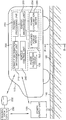
- Fig. 1 is a diagram showing a configuration of a billing system for an electrical energy supplied to electric vehicles in accordance with the embodiment of the present invention
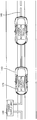
- Fig. 2A is a schematic diagram showing a configuration of the wireless power supply system shown in Fig. 1;
- Fig. 2B illustrates a cross sectional view taken along lines II-II of the power supply track shown in Fig. 1;
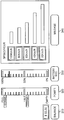
- Fig. 3 illustrates an exemplary view on a dashboard displayed by the energy management unit in accordance with the embodiment of the present invention.
- Fig. 4 is a flowchart describing a billing method for an electrical energy supplied electric vehicles in accordance with the embodiment of the present invention.
- Fig. 1 is a diagram of illustrating a billing system for an electrical energy supplied to electric vehicles in accordance with the embodiment of the present invention.
- the billing system of the present invention includes a wireless power supply system including the power supply unit 130 and the power supply track 140 to supply an electrical energy for operating electrical vehicles 110, and a power acquisition device 120 that is installed on the respective electric vehicles 110 to acquire the electrical energy from the power supply track 140.
- Fig. 2A is a schematic diagram showing a configuration of the wireless power supply system shown in Fig. 1, and Fig. 2B illustrates a cross sectional view taken along lines II-II of the power supply track shown in Fig. 1.
- the power supply unit 130 supplies electrical power to the power supply track 140.
- the power supply track (or rail) 140 is embedded within a road 160 on which the electric vehicles 110 is travelling and extends along the longitudinal direction of the road 160.
- the power supply track 140 includes a power supply line 142, an insulator 144 and a power supply core 146 are sequentially stacked in a top-down fashion.
- the power supply line 142 is formed of a conductive material, for example, copper or aluminum material, and the power supply core 146 is formed of a magnetic body.
- the insulator 144 electrically insulates the power supply line 142 from the power supply core 146.
- One end of the power supply line 142 is connected to an output end of the power supply unit 130 and the other end of the power supply line 142 is connected back to an input end of the power supply unit 130.
- EMF electromagnetic field
- the power acquisition device 120 is mounted beneath the respective electric vehicles 110 in a position to acquire the electrical energy on the road 160 even while the electric vehicles are travelling.
- the electric vehicles 110 charge a battery (not shown) with the electrical energy acquired through the power acquisition device 120 to supply loads of the electric vehicle 110 such as a driving motor or an air conditioner with the electrical power.
- the power supply unit 130 and the power supply track 140 are not installed along the entire length of the road 160 but installed in each certain section of the road 160 or in an arbitrary section where the electric vehicle 110 is considered to be charged, and the electric vehicles are energized from the power supply track 140.
- One example of the electric vehicles of wireless charging type is disclosed in a PCT publication WO2010/098547, published on September 2, 2010, entitled "POWER SUPPLY DEVICE, POWER ACQUISITION DEVICE AND SAFTY FOR ELECTROMAGNETIC INDUCTION-POWERED ELECTRIC VEHICLE," which is assigned to the assignee of the present application, the entire of which is incorporated herein by reference.
- the electric vehicles of wireless charging type cover any other electrically-operated vehicles as well as that of described in the PCT publication if the wireless power supply system employs the electromagnetic induction scheme.
- the electric vehicle 110 of the wireless charging type acquires the electrical energy from the power supply track 140 in an active state, and therefore, there occurs a need to prevent electric vehicles without paying for the acquisition of the electrical energy.
- the need may be achieved by controlling the power acquisition device 120 in an inactive state depending on the basis of a deposited balance for payment, which will be further disclosed below.
- the billing system further includes a remote billing data center 150 and a payment management module 200 that is installed on the respective electric vehicles 110.
- the billing data center 150 performs a function which manages vehicle information, billing information and user information of the respective electric vehicles.
- vehicle information includes an identifier (ID) of the respective electric vehicles and an identifier (ID) of the respective power acquisition devices 120 in the electric vehicle 110;
- the billing information includes a deposited balance for payment needed to purchase the electrical energy for each electric vehicle;
- the user information includes information on a user’s name, address, credit rating and so on of the respective electric vehicles. All these information are stored in a database 252.
- the billing data center 150 transmits and receives the vehicle information, billing information and user information related to the electric vehicles 110 to and from the payment management module 200 through a broadband wireless communication, for example, CDMA (Code Division Multiple Access) or another wireless communication system such as a wireless LAN (local Area Network), e.g., Wi-Fi (Wireless-Fidelity). Moreover, the billing data center 150 generates a control signal depending on the balance for payment to determine whether or not to permit to supply the electrical energy to electric vehicles that need the electrical energy.
- CDMA Code Division Multiple Access
- Wi-Fi Wireless-Fidelity
- the payment management module 200 manages the acquisition of the electrical energy by the power acquisition device 120 and the payment for the amount of the acquisition of the electrical energy.
- the payment management module 200 includes a vehicle information management unit 210, an energy management unit 220, a payment processing unit 230, and a vehicle control unit 240.
- the vehicle information management unit 210 manages an ID of a corresponding electric vehicle 110 and the ID of a power acquisition device 120 of the corresponding electric vehicle 110, and receives information on the balance for payment of the corresponding electric vehicle 110 from the billing data center 150. More specifically, the vehicle information management unit 210 stores the ID of the electric vehicle 110 and the ID of the power acquisition device 120 therein, transmits the ID of the electrical vehicle 110 to the billing data center 150 when the electric vehicle 110 enters the power supply track 140 on the road 160. Further, the vehicle information management unit 210 receives a current balance for payment of the electric vehicle 110 from the billing data center 150 when the electric vehicle 110 needs feeding of the electrical energy. The received balance is then relayed to the energy management unit 220.
- the power supply system automatically captures an ID the electric vehicle by using a Near Field Communication (NFC) such as Bluetooth when the electric vehicle approaches the power supply track 140, and then transmits the captured ID to the billing data center 150 using a broadband wireless communication such as CDMA.
- NFC Near Field Communication
- CDMA broadband wireless communication
- the energy management unit 220 monitors a State Of Charge (hereinafter referred to as a SOC) in the electric vehicle 110 and provides the user with the monitored SOC, thus enabling the user to recognize the SOC in the electric vehicle 110. Further, the energy management unit 220 receives the information of the balance for payment provided from the vehicle information management unit 210 and displays the balance for payment to the user so that the user can determine to purchase an additional electrical energy depending on the balance for payment. If there is no balance, the energy management unit 220 may notice a message of a necessity of additional energy purchase to the user. When the user determines to make the additional energy purchase, the user requests the payment processing unit 230 to perform the additional energy purchase.
- SOC State Of Charge
- the energy management unit 220 updates the balance from which money for the electrical energy purchase is subtracted while feeding the electrical energy, and continuously informs the billing data center 150 of the updated balance for payment, thus enabling the billing data center 150 to monitor the balance for payment of the electric vehicle.
- the payment processing unit 230 is activated when the user determines to make the electrical energy purchase through the energy management unit 220, and processes the payment for the electrical energy purchase by communication with the billing data center 150.
- the method for payment includes, but not limited to, credit card payment, debit card payment, charged card payment, and mobile banking, for example.
- the payment processing unit 230 may further employs a voice recognition technology to make a payment. It may be desirable that a user makes a payment for the electrical energy purchase through the voice recognition device for the sake of security.
- the vehicle control unit 240 controls the operation of the power acquisition device 120 in response to the control signal from the billing data center 150.
- the vehicle control unit 240 makes the power acquisition device in an activate state when the electric vehicle 110 enters the power supply track 140 on the road 160.
- the payment processing unit 230 If a payment for the additional energy purchase is not made even though there is no balance for payment, the payment processing unit 230 notifies a refusal or an incomplete payment of the additional energy purchase to the billing data center 150, and then the billing data center 150 transmits a control signal, e.g., an inactivate signal to disable the operation of the power acquisition device 120 to the vehicle control unit 240 in order to prevent the an illegal feeding of the electrical energy without charge.
- a control signal e.g., an inactivate signal to disable the operation of the power acquisition device 120 to the vehicle control unit 240 in order to prevent the an illegal feeding of the electrical energy without charge.
- the billing data center 150 transmits the inactivate signal as the control signal, and the vehicle control unit 240 then makes the power acquisition device 120 in an inactive state, so that the electrical energy cannot be charged the electrical vehicle 110.
- Fig. 3 illustrates an exemplary view on a dashboard 300 displayed by the energy management unit 220 in accordance with the embodiment of the present invention.
- the energy management unit 220 monitors a various status of the electric vehicle as well as the SOC thereof to provide the user with the monitored information, thus enabling the user to recognize the statuses of the electric vehicle 11.
- the monitored information includes information on a BALANCE 310, a POWER 320, a BATTERY SOC 330, and a MILEAGE 340 as shown in Fig. 3.
- the POWER 320 indicates the remaining amount of electrical power and may be made by using an oil gauge which indicates a value between Empty and Full or a human machine interface (HMI) that can indicate a value between Empty and Full with 0% to 100%, as shown in Fig. 3.
- HMI human machine interface
- the payment management module 200 further includes an acquired power meter 252 for measuring the total amount of electrical power in real time , and a power consumption meter 254 for measuring the amount of electrical power consumed at each load in the electric vehicle.
- the measured amount of the electrical energy and the measured amount of the electrical energy used in the loads are provided to the energy management unit 220 for presenting them to the user.
- Such acquired power meter 252 and power consumption meter 254 may be implemented using conventional metering equipment.
- the energy management unit 220 enables the user to recognize the balance, the remainder of electrical power, and the battery SOC in real time.
- Fig. 4 is a flowchart describing a billing method for an electrical energy to electric vehicles in accordance with the embodiment of the present invention.
- step 401 when an electric vehicle 110 needs to be charged, the electric vehicle 110 enters the power supply track 140 on the road 160 and starts up the power acquisition device 120 to prepare the acquisition of the electrical energy from the power supply track 140.
- the power acquisition device 120 is started up, an ID of the electric vehicle 110 is provided to the billing data center 150 from the vehicle information management unit 210.
- the vehicle information management unit 210 In response to the receipt of the ID the electrical vehicle 110 that enters the power supply track 140, information on the balance of payment of the electric vehicle 110 is provided to the vehicle information management unit 210 from the billing data center 150 in step 403. Then, the vehicle information management unit 210 transmits the balance for payment to the energy management unit 220, in which the balance for payment is represented to the user through the dashboard 300.
- step 405 the electrical vehicle 110 is charged with the electrical energy acquired by the started-up power acquisition device 120, and during the charging, the balance for payment is updated by subtracting the charging amount from the balance for payment.
- step 407 it is checked whether there is a balance for payment while charging, or whether there is a balance for payment while driving. If there is no balance for payment, the process proceeds to step 409 in which the energy management unit 220 provides the user with a message of a necessity of additional energy purchase. Thereafter, in step 411, it is inquired whether the user determines to make an additional energy purchase. When the user determines to make the additional energy purchase, the process goes to step 415 in which a payment process for the additional energy purchase is performed. In this step, the payment may be made in various ways such as credit card payment, debit card payment, mobile banking, etc.
- the vehicle control unit 240 maintains the power acquisition device 120 in an active state so that the electric vehicle can be additionally charged. That is, when a payment for the additional purchase is successfully completed, the billing data center 150 updates the balance for payment by adding a deposited amount of the additional energy purchase to the balance for payment, transmits the updated balance for payment to the vehicle information management unit 210, and sends the control signal to activate the power acquisition device 120 to the vehicle control unit 240, so that the power acquisition device 120 can continuously acquire an additional electrical energy.
- step 411 when the user determines not to make the additional energy purchase, the energy management unit 220 transmits a refusal or an incomplete payment of the additional energy purchase to the billing data center 150, and in response, the billing data center 150 provides a control signal to the vehicle control unit 240 to make the power acquisition device 120 inactive in step 413.
- the electric vehicle can renew the charging with electrical energy by entering the power supply track 140 and repeating the above steps if necessary.
- the billing system and method for electric vehicles of the wireless charging type allow for electrical energy purchase while driving, by providing information about a balance for payment and state of charge of the electric vehicles and deriving an electrical energy purchase based on the information.
- the billing system and method in accordance with the present invention can control the driving of the power acquisition device in an electric vehicle while monitoring the balance for payment and thus prevent a user who does not pay for expense from illegally using the electric vehicle.
Landscapes
- Engineering & Computer Science (AREA)
- Business, Economics & Management (AREA)
- Power Engineering (AREA)
- Mechanical Engineering (AREA)
- Transportation (AREA)
- General Physics & Mathematics (AREA)
- Physics & Mathematics (AREA)
- Accounting & Taxation (AREA)
- Finance (AREA)
- Economics (AREA)
- General Business, Economics & Management (AREA)
- Strategic Management (AREA)
- Theoretical Computer Science (AREA)
- Sustainable Development (AREA)
- Sustainable Energy (AREA)
- Life Sciences & Earth Sciences (AREA)
- Development Economics (AREA)
- Health & Medical Sciences (AREA)
- General Health & Medical Sciences (AREA)
- Human Resources & Organizations (AREA)
- Marketing (AREA)
- Primary Health Care (AREA)
- Tourism & Hospitality (AREA)
- Public Health (AREA)
- Water Supply & Treatment (AREA)
- Electric Propulsion And Braking For Vehicles (AREA)
Abstract
A billing system for an electrical energy supplied to electric vehicles includes a wireless power supply system installed on a road for generating electrical energy using an electromagnetic induction; a power acquisition device, installed on each electric vehicle, for acquiring the electrical energy; a payment management module, installed on the electric vehicle, for managing the acquisition of the electrical energy and paying for the amount of the acquisition of the electrical energy; and a billing data center for integrally managing vehicle information and billing information for the respective electric vehicles, and for generating a control signal in relation to the acquisition of the electrical energy depending on the billing information.
Description
The present invention relates to a billing system and method for an electrical energy supplied to electric vehicles from a wireless power supply system.
Recently, global warming and resource depletion lead to a development of new recycling energies and the industries using these energies are being spotlighted as a green industry. For example, the reality is that a study on light emitting diodes (LEDs), solar cells, wind power generation, etc. is actively being progressed without precedent, and especially in order to solve the problems such as the exhaustion of petroleum energy and air environmental pollution, a study on electric vehicles is being rapidly conducted.
Charging method of such electric vehicles may be classified into stop charging and non-stop charging, and plug-in charging and wireless charging.
The stop charging is to charge an electrical energy to an electric vehicle using charging equipment or exchanges a battery or fuel cell in the state that the electric vehicle is stopped, like battery driven electric vehicles or fuel cell driven electric vehicles, and the non-stop charging is to charge an electric vehicle with an electrical energy even when the electric vehicle is travelled as well as when it is stopped.
Meanwhile, the plug-in charging is to feed an electrical energy to an electric vehicle by connecting a plug-in cord to the electric vehicle, and the wireless charging is to charge an electric vehicle with an electrical energy without any direct connection line between the electric vehicle and the charging equipment.
Therefore, a billing technology for the electric vehicles should be different depending on the charging types. The billing technology for the stop and the plug-in charging type has been already commercialized but the billing technology for the non-stop and wireless charging type has not been developed yet.
In the case of the electric vehicle of the plug-in charging type, a billing method is applied in which the electric vehicle stops at a place where there is charging equipment or a battery exchange place to charge the needed electrical energy or exchange the battery and then pay for the charged electrical energy or exchanged batery.
On the other hand, in the case of the electric vehicle of the wireless charging type, it is not necessary to stop the electric vehicle for feeding or charging the electrical energy, and it is possible to feed or charge the electrical energy while it is driving. That is, since the electric vehicle of the wireless charging type is fed an electrical energy even while it is driving, it should be possible to purchase the electrical energy for operating the electric vehicle while it driving when the remaining amount of the electrical energy is not sufficient. However, there is no system to support such a purchase to date.
In most of the electrical vehicles, frequent charging/discharging may entail a reduction of the life span of battery and thus lead to an increase of replacement cost of the battery. In order to overcome the above issues, for the wireless charging type of the electrical vehicle, there has been proposed a configuration to directly supply an electrical energy to loads in the electric vehicle during acquiring the electrical energy from a power supply source, without being subjected to the charging/discharging. Therefore, the wireless charging type of electrical vehicle can be driven without the aid of the battery by directly supplying the electrical energy from the power supply source to the loads only at a location where the power supply source is installed.
Therefore, there is a need for a billing system and method that enables electric vehicles of the wireless charging type to purchase an electrical energy regardless of place and time. In addition, there is a need for a billing system and method for preventing electric vehicle that does not pay for electrical energy purchase from illegally charging the electric vehicles.
In view of the foregoing, the present invention provides a billing system and method, which are capable of monitoring a deposited balance for payment to bill for electrical energy purchase.
Further, the present invention provides a billing system and method, which are capable of preventing electric vehicle that does not pay for electrical energy purchase from illegally charging the electric vehicles.
In accordance with the present invention, there is provided a billing system for electrical energy charged into electric vehicles, including:
a wireless power supply system, installed on a road on which the electric vehicles travel, for generating the electrical energy for operating the electrical vehicles using an electromagnetic induction; a power acquisition device, installed on each electric vehicle, for acquiring the electrical energy generated from the power supply system to charge the electrical energy therein; a payment management module, installed on the electric vehicle, for managing the acquisition of the electrical energy and paying for the amount of the acquisition of the electrical energy; and a billing data center for integrally managing vehicle information, and billing information for the respective electric vehicles, and for generating a control signal in relation to the acquisition of the electrical energy depending on the billing information.
Preferably, the payment management module includes: a vehicle information management unit for transmitting an identifier of a corresponding electric vehicle and a serial number of the power acquisition device in the corresponding electric vehicle when entering into the power supply system and receiving a balance for payment of the electric vehicle from the billing data center in response to the entrance of the electric vehicle; an energy management unit for monitoring state of charge of the electric vehicle and providing to a user the monitored state of charge together with the balance for payment provided from the vehicle information management unit; a payment process unit for performing a payment for the amount of the acquisition of the electrical energy by communication with the billing data center with reference to the balance for payment when purchasing the electrical energy from the power supply system; and vehicle control unit for making the power acquisition device in active or inactive in response the control signal generated by the billing data center.
Preferably, the energy management unit provides the user with information on the electrical energy acquired through the power acquisition device from the power supply system.
Preferably, the energy management unit updates the balance for payment by subtracting the amount of the electrical energy charged to the electric vehicle from the balance for payment received from the vehicle information management unit, and transmits the updated balance for payment to the billing data center.
Preferably, the billing system further including: an acquired power meter for measuring the amount of the electrical energy acquired by the power acquisition device; and a power consumption meter for measuring the amount of the electrical energy used in loads in the electric vehicle,
wherein the measured amount of the electrical energy and the measured amount of the electrical energy used in the loads are provided to the energy management unit for present them to the user.
Preferably, the billing data center transmits an in activate signal as the control signal to the vehicle control unit when a payment for the electrical energy purchase is not settled even though there is no balance for payment, and wherein the vehicle control unit sets the the power acquisition device to inactive state in response to the inactivate signal.
Preferably, the payment is performed using any one of a credit card payment, a debit card payment and a mobile banking.
Preferably, the payment is performed through voice recognition.
In accordance with another aspect of the present invention, there is provided a billing method for an electrical energy charged into electric vehicles from a wireless power supply system on a road, including: receiving an identifier of an electric vehicle that enters into the power supply system in a road; monitoring a balance for payment of the electric vehicle; if the balance for payment exists, updating the balance for payment by subtracting the amount of the electrical energy from the balance for payment while charging the electric vehicle; if the balance does not exist, inquiring whether to purchase an additional energy; paying for the additional energy purchase when it is determined to make the additional electrical energy purchase; and making the electric vehicle in an activate state to enable the charging of the additional energy after paying for the additional electrical energy purchase.
Preferably, the method further including: when a payment for the additional electrical energy purchase is not settled, making the electric vehicle inactive state.
Preferably, the electric vehicle is charged in real time while it is travelling on the power supply system on the road.
The above and other objects and features of the present invention will become apparent from the following description of embodiments, given in conjunction with the accompanying drawings, in which:
Fig. 1 is a diagram showing a configuration of a billing system for an electrical energy supplied to electric vehicles in accordance with the embodiment of the present invention;
Fig. 2A is a schematic diagram showing a configuration of the wireless power supply system shown in Fig. 1;
Fig. 2B illustrates a cross sectional view taken along lines II-II of the power supply track shown in Fig. 1;
Fig. 3 illustrates an exemplary view on a dashboard displayed by the energy management unit in accordance with the embodiment of the present invention; and
Fig. 4 is a flowchart describing a billing method for an electrical energy supplied electric vehicles in accordance with the embodiment of the present invention.
Hereinafter, an embodiment of the present invention will be described in detail with the accompanying drawings.
Fig. 1 is a diagram of illustrating a billing system for an electrical energy supplied to electric vehicles in accordance with the embodiment of the present invention.
The billing system of the present invention includes a wireless power supply system including the power supply unit 130 and the power supply track 140 to supply an electrical energy for operating electrical vehicles 110, and a power acquisition device 120 that is installed on the respective electric vehicles 110 to acquire the electrical energy from the power supply track 140.
Fig. 2A is a schematic diagram showing a configuration of the wireless power supply system shown in Fig. 1, and Fig. 2B illustrates a cross sectional view taken along lines II-II of the power supply track shown in Fig. 1.
In the wireless power supply system, the power supply unit 130 supplies electrical power to the power supply track 140. The power supply track (or rail) 140 is embedded within a road 160 on which the electric vehicles 110 is travelling and extends along the longitudinal direction of the road 160.
As shown in Fig. 2B, the power supply track 140 includes a power supply line 142, an insulator 144 and a power supply core 146 are sequentially stacked in a top-down fashion. The power supply line 142 is formed of a conductive material, for example, copper or aluminum material, and the power supply core 146 is formed of a magnetic body. The insulator 144 electrically insulates the power supply line 142 from the power supply core 146. One end of the power supply line 142 is connected to an output end of the power supply unit 130 and the other end of the power supply line 142 is connected back to an input end of the power supply unit 130. When current supplied from the power supply unit 130 flows in the power supply line 146, an electromagnetic field (EMF) is created around the power supply line 142 by a principle of electromagnetic induction, thereby generating the electrical energy for operating the electric vehicle on the road 160.
Referring back to Fig. 1, the power acquisition device 120 is mounted beneath the respective electric vehicles 110 in a position to acquire the electrical energy on the road 160 even while the electric vehicles are travelling.
The electric vehicles 110 charge a battery (not shown) with the electrical energy acquired through the power acquisition device 120 to supply loads of the electric vehicle 110 such as a driving motor or an air conditioner with the electrical power.
The power supply unit 130 and the power supply track 140 are not installed along the entire length of the road 160 but installed in each certain section of the road 160 or in an arbitrary section where the electric vehicle 110 is considered to be charged, and the electric vehicles are energized from the power supply track 140. One example of the electric vehicles of wireless charging type is disclosed in a PCT publication WO2010/098547, published on September 2, 2010, entitled "POWER SUPPLY DEVICE, POWER ACQUISITION DEVICE AND SAFTY FOR ELECTROMAGNETIC INDUCTION-POWERED ELECTRIC VEHICLE," which is assigned to the assignee of the present application, the entire of which is incorporated herein by reference. However, it will be appreciated by those skilled in the art that the electric vehicles of wireless charging type cover any other electrically-operated vehicles as well as that of described in the PCT publication if the wireless power supply system employs the electromagnetic induction scheme.
The electric vehicle 110 of the wireless charging type acquires the electrical energy from the power supply track 140 in an active state, and therefore, there occurs a need to prevent electric vehicles without paying for the acquisition of the electrical energy. According to the present invention, the need may be achieved by controlling the power acquisition device 120 in an inactive state depending on the basis of a deposited balance for payment, which will be further disclosed below.The billing system further includes a remote billing data center 150 and a payment management module 200 that is installed on the respective electric vehicles 110.
The billing data center 150 performs a function which manages vehicle information, billing information and user information of the respective electric vehicles. The vehicle information includes an identifier (ID) of the respective electric vehicles and an identifier (ID) of the respective power acquisition devices 120 in the electric vehicle 110; the billing information includes a deposited balance for payment needed to purchase the electrical energy for each electric vehicle; and the user information includes information on a user’s name, address, credit rating and so on of the respective electric vehicles. All these information are stored in a database 252. The billing data center 150 transmits and receives the vehicle information, billing information and user information related to the electric vehicles 110 to and from the payment management module 200 through a broadband wireless communication, for example, CDMA (Code Division Multiple Access) or another wireless communication system such as a wireless LAN (local Area Network), e.g., Wi-Fi (Wireless-Fidelity). Moreover, the billing data center 150 generates a control signal depending on the balance for payment to determine whether or not to permit to supply the electrical energy to electric vehicles that need the electrical energy.
The payment management module 200 manages the acquisition of the electrical energy by the power acquisition device 120 and the payment for the amount of the acquisition of the electrical energy. The payment management module 200 includes a vehicle information management unit 210, an energy management unit 220, a payment processing unit 230, and a vehicle control unit 240.
The vehicle information management unit 210 manages an ID of a corresponding electric vehicle 110 and the ID of a power acquisition device 120 of the corresponding electric vehicle 110, and receives information on the balance for payment of the corresponding electric vehicle 110 from the billing data center 150. More specifically, the vehicle information management unit 210 stores the ID of the electric vehicle 110 and the ID of the power acquisition device 120 therein, transmits the ID of the electrical vehicle 110 to the billing data center 150 when the electric vehicle 110 enters the power supply track 140 on the road 160. Further, the vehicle information management unit 210 receives a current balance for payment of the electric vehicle 110 from the billing data center 150 when the electric vehicle 110 needs feeding of the electrical energy. The received balance is then relayed to the energy management unit 220.
Alternatively, as described above, it may be possible to configure the billing system, so that the power supply system automatically captures an ID the electric vehicle by using a Near Field Communication (NFC) such as Bluetooth when the electric vehicle approaches the power supply track 140, and then transmits the captured ID to the billing data center 150 using a broadband wireless communication such as CDMA.
The energy management unit 220 monitors a State Of Charge (hereinafter referred to as a SOC) in the electric vehicle 110 and provides the user with the monitored SOC, thus enabling the user to recognize the SOC in the electric vehicle 110. Further, the energy management unit 220 receives the information of the balance for payment provided from the vehicle information management unit 210 and displays the balance for payment to the user so that the user can determine to purchase an additional electrical energy depending on the balance for payment. If there is no balance, the energy management unit 220 may notice a message of a necessity of additional energy purchase to the user. When the user determines to make the additional energy purchase, the user requests the payment processing unit 230 to perform the additional energy purchase. In addition, the energy management unit 220 updates the balance from which money for the electrical energy purchase is subtracted while feeding the electrical energy, and continuously informs the billing data center 150 of the updated balance for payment, thus enabling the billing data center 150 to monitor the balance for payment of the electric vehicle.
The payment processing unit 230 is activated when the user determines to make the electrical energy purchase through the energy management unit 220, and processes the payment for the electrical energy purchase by communication with the billing data center 150. The method for payment includes, but not limited to, credit card payment, debit card payment, charged card payment, and mobile banking, for example. In the present invention, the payment processing unit 230 may further employs a voice recognition technology to make a payment. It may be desirable that a user makes a payment for the electrical energy purchase through the voice recognition device for the sake of security.
The vehicle control unit 240 controls the operation of the power acquisition device 120 in response to the control signal from the billing data center 150. The vehicle control unit 240 makes the power acquisition device in an activate state when the electric vehicle 110 enters the power supply track 140 on the road 160.
If a payment for the additional energy purchase is not made even though there is no balance for payment, the payment processing unit 230 notifies a refusal or an incomplete payment of the additional energy purchase to the billing data center 150, and then the billing data center 150 transmits a control signal, e.g., an inactivate signal to disable the operation of the power acquisition device 120 to the vehicle control unit 240 in order to prevent the an illegal feeding of the electrical energy without charge.
When receiving the incomplete payment, the billing data center 150 transmits the inactivate signal as the control signal, and the vehicle control unit 240 then makes the power acquisition device 120 in an inactive state, so that the electrical energy cannot be charged the electrical vehicle 110.
Fig. 3 illustrates an exemplary view on a dashboard 300 displayed by the energy management unit 220 in accordance with the embodiment of the present invention.
The energy management unit 220 monitors a various status of the electric vehicle as well as the SOC thereof to provide the user with the monitored information, thus enabling the user to recognize the statuses of the electric vehicle 11. The monitored information includes information on a BALANCE 310, a POWER 320, a BATTERY SOC 330, and a MILEAGE 340 as shown in Fig. 3.
As used herein, the POWER 320 indicates the remaining amount of electrical power and may be made by using an oil gauge which indicates a value between Empty and Full or a human machine interface (HMI) that can indicate a value between Empty and Full with 0% to 100%, as shown in Fig. 3.
To provide the user with the monitored information, the payment management module 200 further includes an acquired power meter 252 for measuring the total amount of electrical power in real time , and a power consumption meter 254 for measuring the amount of electrical power consumed at each load in the electric vehicle. The measured amount of the electrical energy and the measured amount of the electrical energy used in the loads are provided to the energy management unit 220 for presenting them to the user. Such acquired power meter 252 and power consumption meter 254 may be implemented using conventional metering equipment.
In brief, the energy management unit 220 enables the user to recognize the balance, the remainder of electrical power, and the battery SOC in real time.
Fig. 4 is a flowchart describing a billing method for an electrical energy to electric vehicles in accordance with the embodiment of the present invention.
First, in step 401, when an electric vehicle 110 needs to be charged, the electric vehicle 110 enters the power supply track 140 on the road 160 and starts up the power acquisition device 120 to prepare the acquisition of the electrical energy from the power supply track 140. When the power acquisition device 120 is started up, an ID of the electric vehicle 110 is provided to the billing data center 150 from the vehicle information management unit 210.
In response to the receipt of the ID the electrical vehicle 110 that enters the power supply track 140, information on the balance of payment of the electric vehicle 110 is provided to the vehicle information management unit 210 from the billing data center 150 in step 403. Then, the vehicle information management unit 210 transmits the balance for payment to the energy management unit 220, in which the balance for payment is represented to the user through the dashboard 300.
Next, in step 405, the electrical vehicle 110 is charged with the electrical energy acquired by the started-up power acquisition device 120, and during the charging, the balance for payment is updated by subtracting the charging amount from the balance for payment.
In following step 407, it is checked whether there is a balance for payment while charging, or whether there is a balance for payment while driving. If there is no balance for payment, the process proceeds to step 409 in which the energy management unit 220 provides the user with a message of a necessity of additional energy purchase. Thereafter, in step 411, it is inquired whether the user determines to make an additional energy purchase. When the user determines to make the additional energy purchase, the process goes to step 415 in which a payment process for the additional energy purchase is performed. In this step, the payment may be made in various ways such as credit card payment, debit card payment, mobile banking, etc.
Subsequently, in step 417, the vehicle control unit 240 maintains the power acquisition device 120 in an active state so that the electric vehicle can be additionally charged. That is, when a payment for the additional purchase is successfully completed, the billing data center 150 updates the balance for payment by adding a deposited amount of the additional energy purchase to the balance for payment, transmits the updated balance for payment to the vehicle information management unit 210, and sends the control signal to activate the power acquisition device 120 to the vehicle control unit 240, so that the power acquisition device 120 can continuously acquire an additional electrical energy.
however, in step 411, when the user determines not to make the additional energy purchase, the energy management unit 220 transmits a refusal or an incomplete payment of the additional energy purchase to the billing data center 150, and in response, the billing data center 150 provides a control signal to the vehicle control unit 240 to make the power acquisition device 120 inactive in step 413.
Next, the electric vehicle can renew the charging with electrical energy by entering the power supply track 140 and repeating the above steps if necessary.
In accordance with the present invention, the billing system and method for electric vehicles of the wireless charging type allow for electrical energy purchase while driving, by providing information about a balance for payment and state of charge of the electric vehicles and deriving an electrical energy purchase based on the information.
In addition, the billing system and method in accordance with the present invention can control the driving of the power acquisition device in an electric vehicle while monitoring the balance for payment and thus prevent a user who does not pay for expense from illegally using the electric vehicle.
While the invention has been shown and described with respect to the particular embodiments, it will be understood by those skilled in the art that various changes and modification may be made without departing from the scope of the present invention as defined in the following claims.
Claims (11)
- A billing system for an electrical energy supplied to electric vehicles, comprising:a wireless power supply system, installed on a road on which the electric vehicles travel, for generating electrical energy for operating the electrical vehicles using an electromagnetic induction;a power acquisition device, installed on each electric vehicle, for acquiring the electrical energy generated from the power supply system to charge the electrical energy therein;a payment management module, installed on the electric vehicle, for managing the acquisition of the electrical energy and paying for the amount of the acquisition of the electrical energy; anda billing data center for integrally managing vehicle information, and billing information for the respective electric vehicles, and for generating a control signal in relation to the acquisition of the electrical energy depending on the billing information.
- The billing system of claim 1, the payment management module includes:a vehicle information management unit for transmitting an identifier of a corresponding electric vehicle when entering into the power supply system and receiving a balance for payment of the electric vehicle from the billing data center in response to the entrance of the electric vehicle;an energy management unit for monitoring state of charge of the electric vehicle and providing to a user the monitored state of charge together with the balance for payment provided from the vehicle information management unit;a payment process unit for performing a payment for the amount of the acquisition of the electrical energy by communication with the billing data center with reference to the balance for payment when purchasing the electrical energy from the power supply system; anda vehicle control unit for making the power acquisition device in active or inactive in response the control signal generated by the billing data center.
- The billing system of claim 1, wherein the energy management unit provides the user with information on the electrical energy acquired through the power acquisition device from the power supply system.
- The billing system of claim 2, wherein the energy management unit updates the balance for payment by subtracting the amount of the electrical energy charged to the electric vehicle from the balance for payment received from the vehicle information management unit, and transmits the updated balance for payment to the billing data center.
- The billing system of claim 2, further comprising:an acquired power meter for measuring the amount of the electrical energy acquired by the power acquisition device;a power consumption meter for measuring the amount of the electrical energy used in loads in the electric vehicle,wherein the measured amount of the electrical energy and the measured amount of the electrical energy used in the loads are provided to the energy management unit for present them to the user.
- The billing system of claim 1, wherein the billing data center transmits an in activate signal as the control signal to the vehicle control unit when a payment for the electrical energy purchase is not settled even though there is no balance for payment, and wherein the vehicle control unit sets the power acquisition device to inactive state in response to the inactivate signal.
- The billing system of claim 1, wherein the payment is performed using any one of a credit card payment, a debit card payment and a mobile banking.
- The billing system of claim 1, wherein the payment is performed through voice recognition.
- A billing method for an electrical energy charged into electrical vehicles from a wireless power supply system on a road, comprising:receiving an identifier of an electric vehicle that enters into the power supply system in a road;monitoring a balance for payment of the electric vehicle;if the balance for payment exists, updating the balance for payment by subtracting the amount of the electrical energy from the balance for payment while charging the electric vehicle;if the balance does not exist, inquiring whether to purchase an additional energy;paying for the additional energy purchase when it is determined to make the additional electrical energy purchase; andmaking the electric vehicle in an activate state to enable the charging of the additional energy after paying for the additional electrical energy purchase.
- The billing method of claim 9, further comprising:when a payment for the additional electrical energy purchase is not settled, making the electric vehicle inactive state.
- The billing method of claim 9 or 10, wherein the electric vehicle is charged in real time while it is driving on the power supply system on the road.
Applications Claiming Priority (2)
| Application Number | Priority Date | Filing Date | Title |
|---|---|---|---|
| KR1020090116455A KR101098246B1 (en) | 2009-11-30 | 2009-11-30 | Charging System and Charging Method of Electric Vehicles |
| KR10-2009-0116455 | 2009-11-30 |
Publications (2)
| Publication Number | Publication Date |
|---|---|
| WO2011065792A2 true WO2011065792A2 (en) | 2011-06-03 |
| WO2011065792A3 WO2011065792A3 (en) | 2011-11-10 |
Family
ID=44067134
Family Applications (1)
| Application Number | Title | Priority Date | Filing Date |
|---|---|---|---|
| PCT/KR2010/008491 Ceased WO2011065792A2 (en) | 2009-11-30 | 2010-11-29 | Billing system and method for electric vehicles |
Country Status (2)
| Country | Link |
|---|---|
| KR (1) | KR101098246B1 (en) |
| WO (1) | WO2011065792A2 (en) |
Cited By (10)
| Publication number | Priority date | Publication date | Assignee | Title |
|---|---|---|---|---|
| CN104539427A (en) * | 2014-12-27 | 2015-04-22 | 中国西电电气股份有限公司 | Wireless charging electricity energy measuring method based on identity verification |
| CN104816646A (en) * | 2015-04-02 | 2015-08-05 | 西安交通大学 | Moving-static compatible wireless electric energy transmission system for electric automobile |
| CN106585394A (en) * | 2016-11-01 | 2017-04-26 | 国网福建省电力有限公司 | Electric automobile intelligent charging device for highways |
| KR101827790B1 (en) | 2016-05-27 | 2018-02-09 | 에스트래픽(주) | Power charging and billing system for moving electric vehicle |
| CN108189696A (en) * | 2018-01-12 | 2018-06-22 | 宁波力芯科信息科技有限公司 | A kind of unmanned plane for being installed on roof wirelessly continues electric system and method |
| JP2019037031A (en) * | 2017-08-10 | 2019-03-07 | 本田技研工業株式会社 | Electric vehicle and electric power transmission system for transmitting electric power to electric vehicle |
| CN109993922A (en) * | 2019-03-05 | 2019-07-09 | 宁波吉利汽车研究开发有限公司 | A kind of wireless charging device based on block chain |
| CN110675016A (en) * | 2019-08-08 | 2020-01-10 | 北京航空航天大学 | Mine car unmanned transportation system cloud intelligent scheduling system based on end edge cloud architecture and charging method |
| CN112488689A (en) * | 2019-09-12 | 2021-03-12 | 北京新能源汽车股份有限公司 | Battery replacement station and battery replacement charging method and device thereof |
| CN115782670A (en) * | 2022-11-23 | 2023-03-14 | 泽清新能源科技有限公司 | A billing method for new energy vehicles under battery replacement mode and energy replenishment |
Families Citing this family (3)
| Publication number | Priority date | Publication date | Assignee | Title |
|---|---|---|---|---|
| KR101372688B1 (en) * | 2011-11-15 | 2014-03-26 | 한국과학기술원 | Recharge/charging system and method of an electric car using mobile device |
| KR101356666B1 (en) * | 2011-12-15 | 2014-02-04 | 한국에너지기술연구원 | power supply system of vehicle, apparatus and method of the same |
| KR102574694B1 (en) * | 2020-10-16 | 2023-09-06 | 에코브 주식회사 | System and method of certifying genuine product of battery for vehicle through user terminal |
Family Cites Families (7)
| Publication number | Priority date | Publication date | Assignee | Title |
|---|---|---|---|---|
| JPH07236204A (en) * | 1994-02-22 | 1995-09-05 | Hitachi Ltd | Method and system for charging electric automobile |
| US6421600B1 (en) * | 1994-05-05 | 2002-07-16 | H. R. Ross Industries, Inc. | Roadway-powered electric vehicle system having automatic guidance and demand-based dispatch features |
| JP3626968B2 (en) * | 2001-08-21 | 2005-03-09 | 一路 藤岡 | Power supply device |
| JP2004246518A (en) * | 2003-02-13 | 2004-09-02 | Toyota Motor Corp | Wireless power receiving equipment and energy supply equipment |
| KR100884188B1 (en) * | 2005-07-01 | 2009-02-17 | 옥은호 | Underground electric rail road and electric vehicle with current collector |
| JP4211860B2 (en) | 2007-04-25 | 2009-01-21 | トヨタ自動車株式会社 | ELECTRIC VEHICLE CHARGE CONTROL DEVICE, ELECTRIC VEHICLE, ELECTRIC VEHICLE CHARGE CONTROL METHOD, AND COMPUTER-READABLE RECORDING MEDIUM CONTAINING PROGRAM FOR CAUSING COMPUTER TO EXECUTE THE CHARGE CONTROL |
| JP5163238B2 (en) | 2008-04-02 | 2013-03-13 | トヨタ自動車株式会社 | Charging service system and charging service station |
-
2009
- 2009-11-30 KR KR1020090116455A patent/KR101098246B1/en not_active Expired - Fee Related
-
2010
- 2010-11-29 WO PCT/KR2010/008491 patent/WO2011065792A2/en not_active Ceased
Cited By (11)
| Publication number | Priority date | Publication date | Assignee | Title |
|---|---|---|---|---|
| CN104539427A (en) * | 2014-12-27 | 2015-04-22 | 中国西电电气股份有限公司 | Wireless charging electricity energy measuring method based on identity verification |
| CN104816646A (en) * | 2015-04-02 | 2015-08-05 | 西安交通大学 | Moving-static compatible wireless electric energy transmission system for electric automobile |
| CN104816646B (en) * | 2015-04-02 | 2017-06-06 | 西安交通大学 | A kind of radio energy transmission system for moving static Campatible electric automobile |
| KR101827790B1 (en) | 2016-05-27 | 2018-02-09 | 에스트래픽(주) | Power charging and billing system for moving electric vehicle |
| CN106585394A (en) * | 2016-11-01 | 2017-04-26 | 国网福建省电力有限公司 | Electric automobile intelligent charging device for highways |
| JP2019037031A (en) * | 2017-08-10 | 2019-03-07 | 本田技研工業株式会社 | Electric vehicle and electric power transmission system for transmitting electric power to electric vehicle |
| CN108189696A (en) * | 2018-01-12 | 2018-06-22 | 宁波力芯科信息科技有限公司 | A kind of unmanned plane for being installed on roof wirelessly continues electric system and method |
| CN109993922A (en) * | 2019-03-05 | 2019-07-09 | 宁波吉利汽车研究开发有限公司 | A kind of wireless charging device based on block chain |
| CN110675016A (en) * | 2019-08-08 | 2020-01-10 | 北京航空航天大学 | Mine car unmanned transportation system cloud intelligent scheduling system based on end edge cloud architecture and charging method |
| CN112488689A (en) * | 2019-09-12 | 2021-03-12 | 北京新能源汽车股份有限公司 | Battery replacement station and battery replacement charging method and device thereof |
| CN115782670A (en) * | 2022-11-23 | 2023-03-14 | 泽清新能源科技有限公司 | A billing method for new energy vehicles under battery replacement mode and energy replenishment |
Also Published As
| Publication number | Publication date |
|---|---|
| KR101098246B1 (en) | 2011-12-23 |
| KR20110059992A (en) | 2011-06-08 |
| WO2011065792A3 (en) | 2011-11-10 |
Similar Documents
| Publication | Publication Date | Title |
|---|---|---|
| JP6743198B2 (en) | User authentication outlet, power intermediary connector, and power demand device | |
| CN105186631B (en) | A kind of intelligent charging system of electric vehicle, communication terminal and charge control method | |
| US9751417B2 (en) | Method, system, and apparatus for distributing electricity to electric vehicles, monitoring the distribution thereof, and/or providing automated billing | |
| CN101895137B (en) | Method to facilitate opportunity charging of an electric vehicle | |
| US9428067B2 (en) | Vehicle running management system under renewable energy | |
| EP3684084B1 (en) | Device and method for varying communication path of electric vehicle charger | |
| WO2020022679A1 (en) | Integrated charging and payment management system for electric vehicle | |
| CN107554318A (en) | Control box, electric vehicle charging method and supply equipment communication controler on cable | |
| CN112311041A (en) | Shared battery system and method for controlling battery and mobile sharing service system | |
| WO2017217822A1 (en) | System and method for replacing electric car battery | |
| US20100161517A1 (en) | Systems and methods for electricity metering for vehicular applications | |
| WO2013180324A1 (en) | Multi-functional electric vehicle charging device for dc distribution networks utilizing high capacity dc/dc converter | |
| US20200101862A1 (en) | Charging management system | |
| JP2012161241A (en) | Power supply system for electric vehicles | |
| KR20210142153A (en) | Method and apparatus for modular charging station | |
| KR20110059992A (en) | Charging System and Charging Method of Electric Vehicles | |
| JP2012510255A (en) | Measurement / measurement point system and method for measurement / measurement of electrical energy | |
| KR20120111819A (en) | A multi-functional electric vehicle charging device for dc distribution networks using high capacity dc/dc converter | |
| CN111277558B (en) | Method and apparatus for protecting confidential information in an electric vehicle power transmission system | |
| KR20220010591A (en) | Charging Apparatus for Electric Vehicles Capable of Balancing Loads | |
| CN114954052A (en) | Function expansion module for charging station | |
| WO2015102151A1 (en) | Power management method using battery pack for electric car | |
| JP2018129994A (en) | Electric vehicle charging device and electric vehicle charging method | |
| WO2012091435A2 (en) | Method and device for accounting electricity charges for contactless electric vehicle | |
| KR20220050114A (en) | A Processing System for a Home Charging Payment of a Electric Vehicle and a Method for Utilizing a Charging Data with the Same |
Legal Events
| Date | Code | Title | Description |
|---|---|---|---|
| 121 | Ep: the epo has been informed by wipo that ep was designated in this application |
Ref document number: 10833604 Country of ref document: EP Kind code of ref document: A1 |
|
| NENP | Non-entry into the national phase |
Ref country code: DE |
|
| 122 | Ep: pct application non-entry in european phase |
Ref document number: 10833604 Country of ref document: EP Kind code of ref document: A2 |