WO2011064814A1 - 空気調和装置 - Google Patents
空気調和装置 Download PDFInfo
- Publication number
- WO2011064814A1 WO2011064814A1 PCT/JP2009/006335 JP2009006335W WO2011064814A1 WO 2011064814 A1 WO2011064814 A1 WO 2011064814A1 JP 2009006335 W JP2009006335 W JP 2009006335W WO 2011064814 A1 WO2011064814 A1 WO 2011064814A1
- Authority
- WO
- WIPO (PCT)
- Prior art keywords
- heat medium
- heat
- refrigerant
- heat exchanger
- switching device
- Prior art date
Links
Images


Classifications
-
- F—MECHANICAL ENGINEERING; LIGHTING; HEATING; WEAPONS; BLASTING
- F25—REFRIGERATION OR COOLING; COMBINED HEATING AND REFRIGERATION SYSTEMS; HEAT PUMP SYSTEMS; MANUFACTURE OR STORAGE OF ICE; LIQUEFACTION SOLIDIFICATION OF GASES
- F25B—REFRIGERATION MACHINES, PLANTS OR SYSTEMS; COMBINED HEATING AND REFRIGERATION SYSTEMS; HEAT PUMP SYSTEMS
- F25B13/00—Compression machines, plants or systems, with reversible cycle
-
- F—MECHANICAL ENGINEERING; LIGHTING; HEATING; WEAPONS; BLASTING
- F25—REFRIGERATION OR COOLING; COMBINED HEATING AND REFRIGERATION SYSTEMS; HEAT PUMP SYSTEMS; MANUFACTURE OR STORAGE OF ICE; LIQUEFACTION SOLIDIFICATION OF GASES
- F25B—REFRIGERATION MACHINES, PLANTS OR SYSTEMS; COMBINED HEATING AND REFRIGERATION SYSTEMS; HEAT PUMP SYSTEMS
- F25B2313/00—Compression machines, plants or systems with reversible cycle not otherwise provided for
- F25B2313/023—Compression machines, plants or systems with reversible cycle not otherwise provided for using multiple indoor units
- F25B2313/0231—Compression machines, plants or systems with reversible cycle not otherwise provided for using multiple indoor units with simultaneous cooling and heating
-
- F—MECHANICAL ENGINEERING; LIGHTING; HEATING; WEAPONS; BLASTING
- F25—REFRIGERATION OR COOLING; COMBINED HEATING AND REFRIGERATION SYSTEMS; HEAT PUMP SYSTEMS; MANUFACTURE OR STORAGE OF ICE; LIQUEFACTION SOLIDIFICATION OF GASES
- F25B—REFRIGERATION MACHINES, PLANTS OR SYSTEMS; COMBINED HEATING AND REFRIGERATION SYSTEMS; HEAT PUMP SYSTEMS
- F25B2313/00—Compression machines, plants or systems with reversible cycle not otherwise provided for
- F25B2313/027—Compression machines, plants or systems with reversible cycle not otherwise provided for characterised by the reversing means
- F25B2313/02732—Compression machines, plants or systems with reversible cycle not otherwise provided for characterised by the reversing means using two three-way valves
-
- F—MECHANICAL ENGINEERING; LIGHTING; HEATING; WEAPONS; BLASTING
- F25—REFRIGERATION OR COOLING; COMBINED HEATING AND REFRIGERATION SYSTEMS; HEAT PUMP SYSTEMS; MANUFACTURE OR STORAGE OF ICE; LIQUEFACTION SOLIDIFICATION OF GASES
- F25B—REFRIGERATION MACHINES, PLANTS OR SYSTEMS; COMBINED HEATING AND REFRIGERATION SYSTEMS; HEAT PUMP SYSTEMS
- F25B2313/00—Compression machines, plants or systems with reversible cycle not otherwise provided for
- F25B2313/027—Compression machines, plants or systems with reversible cycle not otherwise provided for characterised by the reversing means
- F25B2313/02741—Compression machines, plants or systems with reversible cycle not otherwise provided for characterised by the reversing means using one four-way valve
-
- F—MECHANICAL ENGINEERING; LIGHTING; HEATING; WEAPONS; BLASTING
- F25—REFRIGERATION OR COOLING; COMBINED HEATING AND REFRIGERATION SYSTEMS; HEAT PUMP SYSTEMS; MANUFACTURE OR STORAGE OF ICE; LIQUEFACTION SOLIDIFICATION OF GASES
- F25B—REFRIGERATION MACHINES, PLANTS OR SYSTEMS; COMBINED HEATING AND REFRIGERATION SYSTEMS; HEAT PUMP SYSTEMS
- F25B25/00—Machines, plants or systems, using a combination of modes of operation covered by two or more of the groups F25B1/00 - F25B23/00
- F25B25/005—Machines, plants or systems, using a combination of modes of operation covered by two or more of the groups F25B1/00 - F25B23/00 using primary and secondary systems
-
- F—MECHANICAL ENGINEERING; LIGHTING; HEATING; WEAPONS; BLASTING
- F25—REFRIGERATION OR COOLING; COMBINED HEATING AND REFRIGERATION SYSTEMS; HEAT PUMP SYSTEMS; MANUFACTURE OR STORAGE OF ICE; LIQUEFACTION SOLIDIFICATION OF GASES
- F25B—REFRIGERATION MACHINES, PLANTS OR SYSTEMS; COMBINED HEATING AND REFRIGERATION SYSTEMS; HEAT PUMP SYSTEMS
- F25B2500/00—Problems to be solved
- F25B2500/19—Calculation of parameters
-
- F—MECHANICAL ENGINEERING; LIGHTING; HEATING; WEAPONS; BLASTING
- F25—REFRIGERATION OR COOLING; COMBINED HEATING AND REFRIGERATION SYSTEMS; HEAT PUMP SYSTEMS; MANUFACTURE OR STORAGE OF ICE; LIQUEFACTION SOLIDIFICATION OF GASES
- F25B—REFRIGERATION MACHINES, PLANTS OR SYSTEMS; COMBINED HEATING AND REFRIGERATION SYSTEMS; HEAT PUMP SYSTEMS
- F25B2500/00—Problems to be solved
- F25B2500/26—Problems to be solved characterised by the startup of the refrigeration cycle
-
- F—MECHANICAL ENGINEERING; LIGHTING; HEATING; WEAPONS; BLASTING
- F25—REFRIGERATION OR COOLING; COMBINED HEATING AND REFRIGERATION SYSTEMS; HEAT PUMP SYSTEMS; MANUFACTURE OR STORAGE OF ICE; LIQUEFACTION SOLIDIFICATION OF GASES
- F25B—REFRIGERATION MACHINES, PLANTS OR SYSTEMS; COMBINED HEATING AND REFRIGERATION SYSTEMS; HEAT PUMP SYSTEMS
- F25B2600/00—Control issues
- F25B2600/25—Control of valves
- F25B2600/2513—Expansion valves
Definitions
- the present invention relates to an air conditioner applied to, for example, a building multi air conditioner.
- an air conditioner such as a multi air conditioning system for buildings
- a cooling operation or a heating operation is performed by circulating a refrigerant between an outdoor unit that is a heat source unit arranged outdoors and an indoor unit arranged indoors.
- the air-conditioning target space is cooled or heated by air heated by heat released from the refrigerant or air cooled by heat absorbed by the refrigerant.
- an HFC (hydrofluorocarbon) refrigerant is often used.
- a natural refrigerant such as carbon dioxide (CO 2 ) has been proposed.
- air conditioners with other configurations, such as chiller systems.
- a heat exchanger such as water or antifreeze liquid is heated or cooled by a heat exchanger arranged in the outdoor unit, which is then air-conditioned It is transported to a fan coil unit or a panel heater, which is an indoor unit disposed in the room, and cooling or heating is performed (for example, see Patent Document 1).
- an air conditioner configured such that a heat exchanger for a primary refrigerant and a secondary refrigerant is disposed in the vicinity of each indoor unit, and the secondary refrigerant is conveyed to the indoor unit (for example, Patent Document 3). reference).
- an air conditioner configured to connect an outdoor unit and a branch unit having a heat exchanger with two pipes and transport a secondary refrigerant to the indoor unit (for example, (See Patent Document 4).
- Japanese Patent Laying-Open No. 2005-140444 page 4, FIG. 1, etc.
- JP-A-5-280818 (4th, 5th page, FIG. 1 etc.)
- Japanese Patent Laid-Open No. 2001-289465 pages 5 to 8, FIG. 1, FIG. 2, etc.
- JP 2003-343936 A (Page 5, FIG. 1)
- the present invention provides an air conditioner that can improve energy efficiency and save energy by adjusting the flow rates of the refrigerant and the heat medium related to heat exchange.
- the air conditioner according to the present invention includes a compressor for pressurizing the refrigerant, a refrigerant flow switching device for switching the circulation path of the refrigerant, a heat source side heat exchanger for exchanging heat of the refrigerant, and heat exchange with the refrigerant.
- a refrigerant circuit in which a plurality of heat exchangers for heat medium that heat or cool a heat medium different from the refrigerant and a plurality of expansion devices that respectively adjust the flow rate of the refrigerant flowing to the heat exchangers for heat medium by pressure adjustment are connected by piping.
- a plurality of heat exchangers between heat media a heat medium delivery device for circulating a heat medium related to heat exchange of the heat exchangers between heat media, and air related to the air conditioning target space
- a heat medium side device that constitutes a heat medium circulation circuit by pipe connection of a use side heat exchanger that performs heat exchange on the heat medium inflow side and outflow side of the utilization side heat exchanger in the heat medium circulation circuit Opening adjustment
- a heat medium flow switching device that joins or distributes the heat medium with an arbitrary ratio of opening areas communicating with the plurality of heat medium heat exchangers, and all the heat medium heat exchangers cool the heat medium.
- the heat medium flow path so that the flow rate of the heat medium flowing out to each heat exchanger is the same.
- a control device for controlling the opening degree of the switching device.
- the opening degree of the heat medium flow switching device is controlled, and the flow rate of the heat medium flowing out to each heat exchanger between the heat mediums is set in each flow path. Since it is made the same regardless of the resistance, in order to make the heat exchange amount in each heat exchanger related to heat the same, the flow rate of each refrigerant flowing in each heat exchanger is also the same, so An air conditioner that is efficient and can save energy can be obtained.
- FIG. 1 The system block diagram of the air conditioning apparatus which concerns on Embodiment 1 of this invention.
- FIG. The system circuit diagram at the time of the heating only operation mode of the air conditioning apparatus which concerns on Embodiment 1.
- FIG. FIG. 3 is a system circuit diagram of the air-conditioning apparatus according to Embodiment 1 in a cooling main operation mode.
- FIG. 3 is a system circuit diagram of the air-conditioning apparatus according to Embodiment 1 in a heating main operation mode.
- FIG. 3 is a system circuit diagram of the air-conditioning apparatus according to Embodiment 1 in a heating main operation mode.
- FIG. 1 and 2 are schematic diagrams illustrating an installation example of an air-conditioning apparatus according to an embodiment of the present invention. Based on FIG. 1 and FIG. 2, the installation example of an air conditioning apparatus is demonstrated.
- This air conditioner uses a refrigeration cycle (refrigerant circulation circuit A, heat medium circulation circuit B) that circulates refrigerant (heat source side refrigerant, heat medium) so that each indoor unit can be in the cooling mode or the heating mode as an operation mode. It can be freely selected.
- refrigerant circulation circuit A, heat medium circulation circuit B that circulates refrigerant (heat source side refrigerant, heat medium) so that each indoor unit can be in the cooling mode or the heating mode as an operation mode. It can be freely selected.
- refrigerant circulation circuit A heat medium circulation circuit B
- refrigerant circulation circuit A heat source side refrigerant, heat medium
- the relationship of the size of each component may be different from the actual one.
- the air conditioner according to the present embodiment includes one outdoor unit 1 that is a heat source unit, a plurality of indoor units 2, and heat that is interposed between the outdoor unit 1 and the indoor unit 2. And a medium converter 3.
- the heat medium relay unit 3 performs heat exchange between the heat source side refrigerant and the heat medium.
- the outdoor unit 1 and the heat medium relay unit 3 are connected by a refrigerant pipe 4 that conducts the heat source side refrigerant.
- the heat medium relay unit 3 and the indoor unit 2 are connected by a pipe (heat medium pipe) 5 that conducts the heat medium.
- the cold or warm heat generated by the outdoor unit 1 is delivered to the indoor unit 2 via the heat medium converter 3.
- the air-conditioning apparatus includes one outdoor unit 1, a plurality of indoor units 2, and a plurality of divided heats interposed between the outdoor unit 1 and the indoor unit 2.
- Medium converter 3 (parent heat medium converter 3a, child heat medium converter 3b).
- the outdoor unit 1 and the parent heat medium converter 3a are connected by a refrigerant pipe 4.
- the parent heat medium converter 3 a and the child heat medium converter 3 b are connected by a refrigerant pipe 4.
- the child heat medium converter 3 b and the indoor unit 2 are connected by a pipe 5.
- the cold or warm heat generated by the outdoor unit 1 is delivered to the indoor unit 2 via the parent heat medium converter 3a and the child heat medium converter 3b.
- the outdoor unit 1 is usually disposed in an outdoor space 6 that is a space outside a building 9 such as a building (for example, a rooftop), and supplies cold or hot heat to the indoor unit 2 via the heat medium converter 3. It is.
- the indoor unit 2 is arranged at a position where cooling air or heating air can be supplied to the indoor space 7 that is a space (for example, a living room) inside the building 9, and the cooling air is supplied to the indoor space 7 that is the air-conditioning target space. Alternatively, heating air is supplied.
- the heat medium relay unit 3 is configured as a separate housing from the outdoor unit 1 and the indoor unit 2 and is configured to be installed at a position different from the outdoor space 6 and the indoor space 7. Is connected to the refrigerant pipe 4 and the pipe 5, respectively, and transmits cold heat or hot heat supplied from the outdoor unit 1 to the indoor unit 2.
- the outdoor unit 1 and the heat medium converter 3 use two refrigerant pipes 4, and the heat medium converter 3 and each The indoor unit 2 is connected to each other using two pipes 5.
- each unit (outdoor unit 1, indoor unit 2, and heat medium converter 3) is connected using two pipes (refrigerant pipe 4, pipe 5). Therefore, construction is easy.
- the heat medium converter 3 includes one parent heat medium converter 3 a and two child heat medium converters 3 b (child heat medium converter 3 b (1), derived from the parent heat medium converter 3 a, It can also be divided into a sub-heat medium converter 3b (2)). In this way, a plurality of child heat medium converters 3b can be connected to one parent heat medium converter 3a. In this configuration, there are three refrigerant pipes 4 that connect the parent heat medium converter 3a and the child heat medium converter 3b. Details of this circuit will be described later in detail (see FIG. 3A).
- the heat medium converter 3 is installed in a space such as a ceiling (hereinafter simply referred to as a space 8) that is inside the building 9 but is different from the indoor space 7.
- the state is shown as an example.
- the heat medium relay 3 can also be installed in a common space where there is an elevator or the like.
- 1 and 2 show an example in which the indoor unit 2 is a ceiling cassette type, but the present invention is not limited to this, and the indoor space 7 such as a ceiling-embedded type or a ceiling-suspended type is shown. Any type of air can be used as long as the air for heating or the air for cooling can be blown out directly or by a duct or the like.
- the outdoor unit 1 and 2 show an example in which the outdoor unit 1 is installed in the outdoor space 6, but the present invention is not limited to this.
- the outdoor unit 1 may be installed in an enclosed space such as a machine room with a ventilation opening. If the exhaust heat can be exhausted outside the building 9 by an exhaust duct, the outdoor unit 1 may be installed inside the building 9. It may be installed, or may be installed inside the building 9 when the water-cooled outdoor unit 1 is used. Even if the outdoor unit 1 is installed in such a place, no particular problem occurs.
- the heat medium converter 3 can also be installed in the vicinity of the outdoor unit 1. However, it should be noted that if the distance from the heat medium relay unit 3 to the indoor unit 2 is too long, the power for transporting the heat medium becomes considerably large, and the energy saving effect is diminished. Further, the number of connected outdoor units 1, indoor units 2, and heat medium converters 3 is not limited to the number illustrated in FIGS. 1 and 2, and the air conditioner according to the present embodiment is installed. The number may be determined according to the building 9.
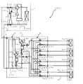
- FIG. 3 is a schematic circuit configuration diagram showing an example of a circuit configuration of the air-conditioning apparatus (hereinafter referred to as the air-conditioning apparatus 100) according to the embodiment. Based on FIG. 3, the detailed structure of the air conditioning apparatus 100 is demonstrated.
- the outdoor unit 1 and the heat medium converter 3 are provided in the heat medium converter 3 and serve as a heating / cooling device.
- the refrigerant pipe 4 is connected via the vessel 15b.
- the heat medium converter 3 and the indoor unit 2 are also connected by a pipe 5 via a heat exchanger related to heat medium 15a and a heat exchanger related to heat medium 15b.
- the heat exchanger related to heat medium 15a and the heat exchanger related to heat medium 15b are assumed to have the same size and the like, and therefore the performance related to heat exchange is the same under the same conditions. It shall be.
- a subscript or the like may be omitted.
- Outdoor unit 1 In the outdoor unit 1, a compressor 10, a first refrigerant flow switching device 11 such as a four-way valve, a heat source side heat exchanger 12, and an accumulator 19 are connected and connected in series through a refrigerant pipe 4. Yes.
- the outdoor unit 1 is provided with a first connection pipe 4a, a second connection pipe 4b, a check valve 13a, a check valve 13b, a check valve 13c, and a check valve 13d. Regardless of the operation that the indoor unit 2 requires, heat is provided by providing the first connection pipe 4a, the second connection pipe 4b, the check valve 13a, the check valve 13b, the check valve 13c, and the check valve 13d.
- the flow of the heat source side refrigerant flowing into the medium converter 3 can be in a certain direction.
- the compressor 10 sucks the heat source side refrigerant and compresses the heat source side refrigerant to be in a high temperature / high pressure state, and may be configured by, for example, an inverter compressor capable of capacity control.
- the first refrigerant flow switching device 11 is used in the heating operation (in the heating only operation mode and in the heating main operation mode) and in the cooling operation (in the cooling only operation mode and the cooling main operation mode).
- the flow of the heat source side refrigerant is switched.
- the heat source side heat exchanger 12 functions as an evaporator during heating operation, functions as a condenser (or radiator) during cooling operation, and between air supplied from a blower such as a fan (not shown) and the heat source side refrigerant. Heat exchange is performed to evaporate or condense the heat-source-side refrigerant.
- the accumulator 19 is provided on the suction side of the compressor 10 and stores excess refrigerant.
- the check valve 13d is provided in the refrigerant pipe 4 between the heat medium converter 3 and the first refrigerant flow switching device 11, and only in a predetermined direction (direction from the heat medium converter 3 to the outdoor unit 1).
- the flow of the heat source side refrigerant is allowed.
- the check valve 13 a is provided in the refrigerant pipe 4 between the heat source side heat exchanger 12 and the heat medium converter 3, and only on a heat source side in a predetermined direction (direction from the outdoor unit 1 to the heat medium converter 3).
- the refrigerant flow is allowed.
- the check valve 13b is provided in the first connection pipe 4a, and causes the heat source side refrigerant discharged from the compressor 10 to flow to the heat medium converter 3 during the heating operation.
- the check valve 13 c is provided in the second connection pipe 4 b and causes the heat source side refrigerant returned from the heat medium relay unit 3 to flow to the suction side of the compressor 10 during the heating operation.
- the first connection pipe 4a is a refrigerant pipe 4 between the first refrigerant flow switching device 11 and the check valve 13d, and a refrigerant between the check valve 13a and the heat medium relay unit 3.
- the pipe 4 is connected.
- the second connection pipe 4b includes a refrigerant pipe 4 between the check valve 13d and the heat medium relay unit 3, and a refrigerant pipe 4 between the heat source side heat exchanger 12 and the check valve 13a.
- FIG. 3 shows an example in which the first connection pipe 4a, the second connection pipe 4b, the check valve 13a, the check valve 13b, the check valve 13c, and the check valve 13d are provided.
- the present invention is not limited to this, and these are not necessarily provided.
- Each indoor unit 2 is equipped with a use side heat exchanger 26.
- the use side heat exchanger 26 is connected to the heat medium flow control device 25 and the second heat medium flow switching device 23 of the heat medium converter 3 by the pipe 5.
- the use-side heat exchanger 26 performs heat exchange between air supplied from a blower such as a fan (not shown) and a heat medium, and generates heating air or cooling air to be supplied to the indoor space 7. To do.
- FIG. 3 shows an example in which four indoor units 2 are connected to the heat medium relay unit 3, and are illustrated as an indoor unit 2a, an indoor unit 2b, an indoor unit 2c, and an indoor unit 2d from the bottom of the page. Show.
- the use side heat exchanger 26 also uses the use side heat exchanger 26a, the use side heat exchanger 26b, the use side heat exchanger 26c, and the use side heat exchange from the lower side of the drawing. It is shown as a container 26d.
- the number of indoor units 2 connected is not limited to four as shown in FIG.
- the heat medium relay 3 includes two heat medium heat exchangers 15, two expansion devices 16, two opening / closing devices 17, two second refrigerant flow switching devices 18, and two pumps 21. Four first heat medium flow switching devices 22, four second heat medium flow switching devices 23, and four heat medium flow control devices 25 are mounted. In addition, what divided the heat medium converter 3 into the parent heat medium converter 3a and the child heat medium converter 3b will be described with reference to FIG. 3A.
- the two heat exchangers between heat media 15 function as a condenser (heat radiator) or an evaporator, and heat is generated by the heat source side refrigerant and the heat medium. Exchange is performed, and the cold or warm heat generated in the outdoor unit 1 and stored in the heat source side refrigerant is transmitted to the heat medium.
- the heat exchanger related to heat medium 15 is, for example, a plate heat exchanger.
- the heat exchanger related to heat medium 15a is provided between the expansion device 16a and the second refrigerant flow switching device 18a in the refrigerant circuit A and serves to cool the heat medium in the cooling / heating mixed operation mode. is there.
- the heat exchanger related to heat medium 15b is provided between the expansion device 16b and the second refrigerant flow switching device 18b in the refrigerant circuit A, and serves to heat the heat medium in the cooling / heating mixed operation mode. Is.
- the two expansion devices 16 have functions as pressure reducing valves and expansion valves, and expand the heat source side refrigerant by reducing the pressure.
- the expansion device 16a is provided on the upstream side of the heat exchanger related to heat medium 15a in the flow of the heat source side refrigerant during the cooling operation.
- the expansion device 16b is provided on the upstream side of the heat exchanger related to heat medium 15b in the flow of the heat source side refrigerant during the cooling operation.
- the two expansion devices 16 may be configured by a device whose opening degree can be variably controlled, for example, an electronic expansion valve.
- the two opening / closing devices 17 are constituted by two-way valves or the like, and open / close the refrigerant pipe 4.
- the opening / closing device 17a is provided in the refrigerant pipe 4 on the inlet side of the heat source side refrigerant.
- the opening / closing device 17b is provided in a pipe connecting the refrigerant pipe 4 on the inlet side and the outlet side of the heat source side refrigerant.
- the two second refrigerant flow switching devices 18 (second refrigerant flow switching device 18a and second refrigerant flow switching device 18b) are constituted by four-way valves or the like, and switch the flow of the heat source side refrigerant according to the operation mode.
- the second refrigerant flow switching device 18a is provided on the downstream side of the heat exchanger related to heat medium 15a in the flow of the heat source side refrigerant during the cooling operation.
- the second refrigerant flow switching device 18b is provided on the downstream side of the heat exchanger related to heat medium 15b in the flow of the heat source side refrigerant in the cooling only operation mode.
- the two pumps 21 serving as the heat medium delivery device circulate the heat medium in the heat medium circuit B.
- the pump 21a is provided between the heat exchanger related to heat medium 15a and the second heat medium flow switching device 23, and circulates the heat medium related to heat exchange of the heat exchanger related to heat medium 15a by driving.
- the pump 21b is provided between the heat exchanger related to heat medium 15b and the second heat medium flow switching device 23, and circulates the heat medium related to heat exchange of the heat exchanger related to heat medium 15b by driving. If there is no communication between the first heat medium flow switching device 22 and the second heat medium flow switching device 23, a circulation path by two independent flow channels is formed.
- the two pumps 21 may be constituted by, for example, pumps capable of capacity control.
- the four first heat medium flow switching devices 22 (first heat medium flow switching device 22a to first heat medium flow switching device 22d) have three inflow / outflow ports (openings) in the present embodiment.
- the flow path of the heat medium is switched.
- a stepping motor driven mixing valve or the like that can change the flow rate of the three-way flow path is used.
- the opening degree can be changed based on an instruction from the control device 50 based on the number of pulses or the like. For this reason, a water hammer can be prevented.
- the first heat medium flow switching device 22 is provided in a number (here, four) according to the number of indoor units 2 installed.
- the first heat medium flow switching device 22 one of the three sides is connected to the heat exchanger related to heat medium 15a (pump 21a), and one of the three sides is connected to the heat exchanger related to heat medium 15b (pump 21b).
- One of them is connected to the heat medium flow control device 25, and is provided on the outlet side (heat medium outflow side) of the heat medium flow path of the use side heat exchanger 26.
- the heat flowing out from the use side heat exchanger 26 (the heat medium flow control device 25) is communicated with either the flow path on the heat exchanger related to heat medium 15b side or the heat exchanger related to heat medium 15a side.
- the medium can flow.
- the four second heat medium flow switching devices 23 (second heat medium flow switching device 23a to second heat medium flow switching device 23d) have three inlet / outlets (openings) in the present embodiment.
- the flow path of the heat medium is switched.
- a device that can change the flow rate of the three-way flow path such as a stepping motor-driven mixing valve is used, and the opening degree is changed based on the number of pulses or the like. Can do.
- the number of the second heat medium flow switching devices 23 is set according to the number of installed indoor units 2 (here, four).
- the second heat medium flow switching device 23 one of the three heat transfer medium heat exchangers 15a, one of the three heat transfer medium heat exchangers 15b, and one of the three heat transfer side heats.
- the heat exchanger is connected to the exchanger 26 and provided on the inlet side of the heat medium flow path of the use side heat exchanger 26.
- the heat medium is communicated with the flow path on either the heat exchanger related to heat medium 15b or the heat exchanger related to heat medium 15a, and the heat medium is supplied to the use-side heat exchanger 26 (heat medium flow control device 25).
- the second heat medium flow switching device 23a, the second heat medium flow switching device 23b, the second heat medium flow switching device 23c, and the second heat medium flow from the lower side of the drawing. This is illustrated as a switching device 23d.
- the first heat medium flow switching device 22 and the second heat medium flow switching device 23 of the present embodiment are stepping motor driven devices, not only switching but also by adjusting the opening degree.
- all the flow paths can be communicated at a ratio of an arbitrary opening area.
- the second heat medium flow switching device 23 merges the heat mediums of the two flow paths and flows them into the use-side heat exchanger 26.
- the first heat medium flow switching device 22 branches the heat medium flowing out from the use side heat exchanger 26 into two flow paths.
- the ratio of the opening areas of the opening portions where the heat medium flows into and out of the pumps 21a and 21b is changed. Can do.
- an opening degree at which the opening areas of the portions where the heat medium flows into and out of the pumps 21a and 21b is approximately the same (ratio 1: 1) is referred to as an intermediate opening degree.
- the four heat medium flow control devices 25 are composed of, for example, a two-way valve using a stepping motor, and the like. The opening degree can be changed, and the flow rate of the heat medium (the amount flowing in unit time) is adjusted.
- the number of the heat medium flow control devices 25 is set according to the number of indoor units 2 installed (four in this case).
- One of the heat medium flow control devices 25 is connected to the use side heat exchanger 26 and the other is connected to the first heat medium flow switching device 22, and is connected to the outlet side of the heat medium flow channel of the use side heat exchanger 26. Is provided.
- the heat medium flow adjustment device 25 a, the heat medium flow adjustment device 25 b, the heat medium flow adjustment device 25 c, and the heat medium flow adjustment device 25 d are illustrated from the lower side of the drawing. Further, the heat medium flow control device 25 may be provided on the inlet side of the heat medium flow path of the use side heat exchanger 26.
- the heat medium relay unit 3 is provided with various detection means (two first temperature sensors 31, four second temperature sensors 34, four third temperature sensors 35, and a pressure sensor 36). Information (temperature information, pressure information) detected by these detection means is sent to a control device 50 that performs overall control of the operation of the air conditioner 100, and the drive frequency of the compressor 10, the rotational speed of the blower (not shown), This is used for control of switching of the first refrigerant flow switching device 11, driving frequency of the pump 21, switching of the second refrigerant flow switching device 18, switching of the flow path of the heat medium, and the like.
- the control apparatus 50 is provided in the outdoor unit 1 here, it is not limited.
- a control device in which processing functions performed by the control device 50 are distributed can be provided in the indoor unit 2 and the heat medium relay unit 3, and processing can be performed while transmitting and receiving signals through a communication line or the like. It can also be provided outside the apparatus.
- the two first temperature sensors 31 are the heat medium flowing out from the heat exchanger related to heat medium 15, that is, the temperature of the heat medium at the outlet of the heat exchanger related to heat medium 15.
- a thermistor may be used.
- the first temperature sensor 31a is provided in the pipe 5 on the inlet side of the pump 21a (the outlet side of the heat exchanger related to heat medium 15a).
- the first temperature sensor 31b is provided in the pipe 5 on the inlet side of the pump 21b (the outlet side of the heat exchanger related to heat medium 15b).
- the four second temperature sensors 34 are provided between the first heat medium flow switching device 22 and the heat medium flow control device 25, and use side heat exchangers.
- the temperature of the heat medium that has flowed out of the heater 26 is detected, and it may be constituted by a thermistor or the like.
- the number of the second temperature sensors 34 (four here) according to the number of indoor units 2 installed is provided. In correspondence with the indoor unit 2, the second temperature sensor 34a, the second temperature sensor 34b, the second temperature sensor 34c, and the second temperature sensor 34d are illustrated from the lower side of the drawing.
- the four third temperature sensors 35 are provided on the inlet side or the outlet side of the heat source side refrigerant of the heat exchanger related to heat medium 15, and the heat exchanger related to heat medium 15
- the temperature of the heat source side refrigerant flowing into the heat source or the temperature of the heat source side refrigerant flowing out of the heat exchanger related to heat medium 15 is detected, and may be composed of a thermistor or the like.
- the third temperature sensor 35a is provided between the heat exchanger related to heat medium 15a and the second refrigerant flow switching device 18a.
- the third temperature sensor 35b is provided between the heat exchanger related to heat medium 15a and the expansion device 16a.
- the third temperature sensor 35c is provided between the heat exchanger related to heat medium 15b and the second refrigerant flow switching device 18b.
- the third temperature sensor 35d is provided between the heat exchanger related to heat medium 15b and the expansion device 16b.
- the pressure sensor 36 is provided between the heat exchanger related to heat medium 15b and the expansion device 16b, and between the heat exchanger related to heat medium 15b and the expansion device 16b. The pressure of the flowing heat source side refrigerant is detected.
- the control device (not shown) is constituted by a microcomputer or the like, and includes the drive frequency of the compressor 10 and the rotational speed of the blower (including ON / OFF) based on detection information from various detection means and instructions from the remote controller. ), Switching of the first refrigerant flow switching device 11, driving of the pump 21, opening of the expansion device 16, opening / closing of the opening / closing device 17, switching of the second refrigerant flow switching device 18, first heat medium flow switching device 22, switching of the second heat medium flow switching device 23, driving of the heat medium flow control device 25, and the like are controlled, and each operation mode to be described later is executed.
- the control device may be provided for each unit, or may be provided in the outdoor unit 1 or the heat medium relay unit 3.
- the pipe 5 that conducts the heat medium is composed of one that is connected to the heat exchanger related to heat medium 15a and one that is connected to the heat exchanger related to heat medium 15b.
- the pipe 5 is branched (here, four branches each) according to the number of indoor units 2 connected to the heat medium relay unit 3.
- the pipe 5 is connected by a first heat medium flow switching device 22 and a second heat medium flow switching device 23.
- the first heat medium flow switching device 22 and the second heat medium flow switching device 23 By controlling the first heat medium flow switching device 22 and the second heat medium flow switching device 23, the heat medium from the heat exchanger related to heat medium 15a flows into the use-side heat exchanger 26, or the heat medium Whether the heat medium from the intermediate heat exchanger 15b flows into the use side heat exchanger 26 is determined.
- the refrigerant in the compressor 10 the first refrigerant flow switching device 11, the heat source side heat exchanger 12, the switching device 17, the second refrigerant flow switching device 18, and the heat exchanger related to heat medium 15a.
- the flow path, the expansion device 16 and the accumulator 19 are connected by the refrigerant pipe 4 to constitute the refrigerant circuit A.
- the switching device 23 is connected by a pipe 5 to constitute a heat medium circulation circuit B. That is, a plurality of usage-side heat exchangers 26 are connected in parallel to each of the heat exchangers between heat media 15, and the heat medium circulation circuit B has a plurality of systems.
- the outdoor unit 1 and the heat medium relay unit 3 are connected via the heat exchanger related to heat medium 15a and the heat exchanger related to heat medium 15b provided in the heat medium converter 3.
- the heat medium relay unit 3 and the indoor unit 2 are also connected to each other via the heat exchanger related to heat medium 15a and the heat exchanger related to heat medium 15b. That is, in the air conditioner 100, the heat source side refrigerant circulating in the refrigerant circuit A and the heat medium circulating in the heat medium circuit B exchange heat in the intermediate heat exchanger 15a and the intermediate heat exchanger 15b. It is like that.
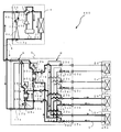
- FIG. 3A is a schematic circuit configuration diagram showing another example of the circuit configuration of the air-conditioning apparatus according to the embodiment (hereinafter, referred to as air-conditioning apparatus 100A).
- air-conditioning apparatus 100A the circuit configuration of the air conditioner 100 ⁇ / b> A when the heat medium relay unit 3 is divided into a parent heat medium relay unit 3 a and a child heat medium relay unit 3 b will be described.
- the heat medium relay unit 3 is configured by dividing the housing into a parent heat medium relay unit 3 a and a child heat medium relay unit 3 b. By configuring in this way, a plurality of child heat medium converters 3b can be connected to one parent heat medium converter 3a as shown in FIG.
- the main heat exchanger 3a is provided with a gas-liquid separator 14 and an expansion device 16c. Other components are mounted on the child heat medium converter 3b.
- the gas-liquid separator 14 includes one refrigerant pipe 4 connected to the outdoor unit 1, and two refrigerants connected to the intermediate heat exchanger 15a and the intermediate heat exchanger 15b of the child heat medium converter 3b.
- the heat source side refrigerant connected to the pipe 4 and supplied from the outdoor unit 1 is separated into a vapor refrigerant and a liquid refrigerant.
- the expansion device 16c is provided on the downstream side in the flow of the liquid refrigerant in the gas-liquid separator 14, has a function as a pressure reducing valve or an expansion valve, expands the heat source side refrigerant by reducing the pressure, and is mixed with cooling and heating. During operation, control is performed so that the pressure state of the refrigerant on the outlet side of the expansion device 16c is set to an intermediate pressure.
- the expansion device 16c may be configured by a device whose opening degree can be variably controlled, for example, an electronic expansion valve. With this configuration, a plurality of child heat medium converters 3b can be connected to the parent heat medium converter 3a.
- the air conditioner 100 can perform a cooling operation or a heating operation in the indoor unit 2 based on an instruction from each indoor unit 2. That is, the air conditioning apparatus 100 can perform the same operation for all the indoor units 2 and can perform different operations for each of the indoor units 2.
- description is abbreviate
- the air conditioner 100 also includes the air conditioner 100A.
- the operation mode executed by the air conditioner 100 includes a cooling only operation mode in which all the driven indoor units 2 execute a cooling operation, and a heating only operation in which all the driven indoor units 2 execute a heating operation. There is a mode. Further, there are a cooling main operation mode in which the cooling load is larger and a heating main operation mode in which the heating load is larger (the cooling main operation mode and the heating main operation mode may be collectively referred to as a cooling / heating mixed operation mode). Hereinafter, each operation mode will be described together with the flow of the heat source side refrigerant and the heat medium.
- FIG. 4 is a refrigerant circuit diagram illustrating a refrigerant flow when the air-conditioning apparatus 100 is in the cooling only operation mode.
- the cooling only operation mode will be described by taking as an example a case where a cooling load is generated only in the use side heat exchanger 26a and the use side heat exchanger 26b.
- the pipes represented by the thick lines indicate the pipes through which the refrigerant (heat source side refrigerant and heat medium) flows.
- the flow direction of the heat source side refrigerant is indicated by solid line arrows
- the flow direction of the heat medium is indicated by broken line arrows.
- the first refrigerant flow switching device 11 is switched so that the heat source side refrigerant discharged from the compressor 10 flows into the heat source side heat exchanger 12.
- the pump 21a and the pump 21b are driven, the heat medium flow control device 25a and the heat medium flow control device 25b are opened, the heat medium flow control device 25c and the heat medium flow control device 25d are closed, The heat medium is circulated between each of the intermediate heat exchanger 15a and the intermediate heat exchanger 15b and the use side heat exchanger 26a and the use side heat exchanger 26b.
- the low-temperature and low-pressure refrigerant is compressed by the compressor 10 and discharged as a high-temperature and high-pressure gas refrigerant.
- the high-temperature and high-pressure gas refrigerant discharged from the compressor 10 flows into the heat source side heat exchanger 12 via the first refrigerant flow switching device 11. Then, the heat source side heat exchanger 12 condenses and liquefies while radiating heat to the outdoor air, and becomes a high-pressure liquid refrigerant.
- the high-pressure liquid refrigerant that has flowed out of the heat source side heat exchanger 12 flows out of the outdoor unit 1 through the check valve 13a, and flows into the heat medium relay unit 3 through the refrigerant pipe 4.
- the high-pressure liquid refrigerant flowing into the heat medium relay unit 3 is branched after passing through the opening / closing device 17a and expanded by the expansion device 16a and the expansion device 16b to become a low-temperature / low-pressure two-phase refrigerant.
- This two-phase refrigerant flows into each of the heat exchanger related to heat medium 15a and the heat exchanger related to heat medium 15b acting as an evaporator, and absorbs heat from the heat medium circulating in the heat medium circulation circuit B. It becomes a low-temperature, low-pressure gas refrigerant while cooling.
- the gas refrigerant flowing out from the heat exchanger related to heat medium 15a and the heat exchanger related to heat medium 15b flows out from the heat medium converter 3 via the second refrigerant flow switching device 18a and the second refrigerant flow switching device 18b.
- the refrigerant flows into the outdoor unit 1 again through the refrigerant pipe 4.
- the refrigerant flowing into the outdoor unit 1 passes through the check valve 13d and is sucked into the compressor 10 again via the first refrigerant flow switching device 11 and the accumulator 19.
- the opening of the expansion device 16a is such that the superheat (superheat degree) obtained as the difference between the temperature detected by the third temperature sensor 35a and the temperature detected by the third temperature sensor 35b is constant. Be controlled.
- the opening degree of the expansion device 16b is controlled so that the superheat obtained as the difference between the temperature detected by the third temperature sensor 35c and the temperature detected by the third temperature sensor 35d is constant.
- the opening / closing device 17a is open and the opening / closing device 17b is closed.
- the flow of the heat medium in the heat medium circuit B will be described.
- the cold heat of the heat source side refrigerant is transmitted to the heat medium in both the heat exchanger 15a and the heat exchanger 15b, and the cooled heat medium is piped 5 by the pump 21a and the pump 21b.
- the inside will be allowed to flow.
- the heat medium pressurized and discharged by the pump 21a and the pump 21b passes through the second heat medium flow switching device 23a and the second heat medium flow switching device 23b, and the use side heat exchanger 26a and the use side heat exchange. Flows into the vessel 26b.
- the heat medium absorbs heat from the indoor air in the use side heat exchanger 26a and the use side heat exchanger 26b, thereby cooling the indoor space 7.
- the heat medium flows out of the use-side heat exchanger 26a and the use-side heat exchanger 26b and flows into the heat medium flow control device 25a and the heat medium flow control device 25b.
- the heat medium flow control device 25a and the heat medium flow control device 25b are operated to control the flow rate of the heat medium to a flow rate necessary to cover the air conditioning load required indoors, so that the use side heat exchanger 26a. And it flows into the use side heat exchanger 26b.
- the heat medium flowing out of the heat medium flow control device 25a and the heat medium flow control device 25b passes through the first heat medium flow switching device 22a and the first heat medium flow switching device 22b, and the heat exchanger related to heat medium 15a. And flows into the heat exchanger related to heat medium 15b, and is sucked into the pump 21a and the pump 21b again.
- the heat medium is directed from the second heat medium flow switching device 23 to the first heat medium flow switching device 22 via the heat medium flow control device 25.
- the air conditioning load required in the indoor space 7 includes the temperature detected by the first temperature sensor 31a, the temperature detected by the first temperature sensor 31b, and the temperature detected by the second temperature sensor 34. It is possible to cover by controlling so that the difference between the two is kept at the target value.
- the outlet temperature of the heat exchanger related to heat medium 15 either the temperature of the first temperature sensor 31a or the first temperature sensor 31b may be used, or the average temperature thereof may be used.
- the first heat medium flow switching device 22 and the second heat medium flow switching device 23 ensure a flow path that flows to both the heat exchanger related to heat medium 15a and the heat exchanger related to heat medium 15b.
- an intermediate opening degree is used for communication.
- FIG. 5 is a refrigerant circuit diagram illustrating a refrigerant flow when the air-conditioning apparatus 100 is in the heating only operation mode.
- the heating only operation mode will be described by taking as an example a case where a thermal load is generated only in the use side heat exchanger 26a and the use side heat exchanger 26b.
- pipes represented by thick lines indicate pipes through which the refrigerant (heat source side refrigerant and heat medium) flows.
- the flow direction of the heat source side refrigerant is indicated by solid line arrows
- the flow direction of the heat medium is indicated by broken line arrows.
- the first refrigerant flow switching device 11 uses the heat source side refrigerant discharged from the compressor 10 without passing through the heat source side heat exchanger 12. It switches so that it may flow into converter 3.
- the pump 21a and the pump 21b are driven, the heat medium flow control device 25a and the heat medium flow control device 25b are opened, the heat medium flow control device 25c and the heat medium flow control device 25d are closed, The heat medium is circulated between each of the intermediate heat exchanger 15a and the intermediate heat exchanger 15b and the use side heat exchanger 26a and the use side heat exchanger 26b.
- the low-temperature and low-pressure refrigerant is compressed by the compressor 10 and discharged as a high-temperature and high-pressure gas refrigerant.
- the high-temperature and high-pressure gas refrigerant discharged from the compressor 10 passes through the first refrigerant flow switching device 11, conducts through the first connection pipe 4 a, passes through the check valve 13 b, and flows out of the outdoor unit 1.
- the high-temperature and high-pressure gas refrigerant that has flowed out of the outdoor unit 1 flows into the heat medium relay unit 3 through the refrigerant pipe 4.
- the high-temperature and high-pressure gas refrigerant that has flowed into the heat medium relay unit 3 is branched and passes through the second refrigerant flow switching device 18a and the second refrigerant flow switching device 18b, and the heat exchanger related to heat medium 15a and the heat medium. It flows into each of the intermediate heat exchangers 15b.
- the high-temperature and high-pressure gas refrigerant flowing into the heat exchanger related to heat medium 15a and the heat exchanger related to heat medium 15b is condensed and liquefied while dissipating heat to the heat medium circulating in the heat medium circulation circuit B, and becomes a high-pressure liquid refrigerant. .
- the liquid refrigerant flowing out from the heat exchanger related to heat medium 15a and the heat exchanger related to heat medium 15b is expanded by the expansion device 16a and the expansion device 16b to become a low-temperature / low-pressure two-phase refrigerant.
- the two-phase refrigerant flows out of the heat medium relay unit 3 through the opening / closing device 17b, and flows into the outdoor unit 1 through the refrigerant pipe 4 again.
- the refrigerant flowing into the outdoor unit 1 is conducted through the second connection pipe 4b, passes through the check valve 13c, and flows into the heat source side heat exchanger 12 that functions as an evaporator.
- the refrigerant that has flowed into the heat source side heat exchanger 12 absorbs heat from the outdoor air by the heat source side heat exchanger 12, and becomes a low-temperature and low-pressure gas refrigerant.
- the low-temperature and low-pressure gas refrigerant flowing out from the heat source side heat exchanger 12 is again sucked into the compressor 10 via the first refrigerant flow switching device 11 and the accumulator 19.
- the expansion device 16a has a constant subcool (degree of subcooling) obtained as a difference between a value obtained by converting the pressure detected by the pressure sensor 36 into a saturation temperature and a temperature detected by the third temperature sensor 35b.
- the opening degree is controlled.
- the expansion device 16b has an opening degree so that a subcool obtained as a difference between a value obtained by converting the pressure detected by the pressure sensor 36 into a saturation temperature and a temperature detected by the third temperature sensor 35d is constant. Be controlled.
- the opening / closing device 17a is closed and the opening / closing device 17b is open.
- the temperature at the intermediate position may be used instead of the pressure sensor 36, and the system can be configured at low cost.
- the heat of the heat source side refrigerant is transmitted to the heat medium in both the heat exchanger 15a and the heat exchanger 15b, and the heated heat medium is piped 5 by the pump 21a and the pump 21b.
- the inside will be allowed to flow.
- the heat medium pressurized and discharged by the pump 21a and the pump 21b passes through the second heat medium flow switching device 23a and the second heat medium flow switching device 23b, and the use side heat exchanger 26a and the use side heat exchange. Flows into the vessel 26b.
- the heat medium radiates heat to the indoor air in the use side heat exchanger 26a and the use side heat exchanger 26b, thereby heating the indoor space 7.
- the heat medium flows out of the use-side heat exchanger 26a and the use-side heat exchanger 26b and flows into the heat medium flow control device 25a and the heat medium flow control device 25b.
- the heat medium flow control device 25a and the heat medium flow control device 25b are operated to control the flow rate of the heat medium to a flow rate necessary to cover the air conditioning load required indoors, so that the use side heat exchanger 26a. And it flows into the use side heat exchanger 26b.
- the heat medium flowing out of the heat medium flow control device 25a and the heat medium flow control device 25b passes through the first heat medium flow switching device 22a and the first heat medium flow switching device 22b, and the heat exchanger related to heat medium 15a. And flows into the heat exchanger related to heat medium 15b, and is sucked into the pump 21a and the pump 21b again.
- the heat medium is directed from the second heat medium flow switching device 23 to the first heat medium flow switching device 22 via the heat medium flow control device 25.
- the air conditioning load required in the indoor space 7 includes the temperature detected by the first temperature sensor 31a, the temperature detected by the first temperature sensor 31b, and the temperature detected by the second temperature sensor 34. It is possible to cover by controlling so that the difference between the two is kept at the target value.
- the outlet temperature of the heat exchanger related to heat medium 15 either the temperature of the first temperature sensor 31a or the first temperature sensor 31b may be used, or the average temperature thereof may be used.
- the first heat medium flow switching device 22 and the second heat medium flow switching device 23 ensure a flow path that flows to both the heat exchanger related to heat medium 15a and the heat exchanger related to heat medium 15b.
- an intermediate opening degree is used for communication.
- An efficient heating operation can be performed by using both the heat exchanger related to heat medium 15a and the heat exchanger related to heat medium 15b for heating the heat medium and increasing the heat transfer area.
- the usage-side heat exchanger 26a should be controlled by the temperature difference between the inlet and the outlet, but the temperature of the heat medium on the inlet side of the usage-side heat exchanger 26 is detected by the first temperature sensor 31b. By using the first temperature sensor 31b, the number of temperature sensors can be reduced and the system can be configured at low cost.
- FIG. 6 is a refrigerant circuit diagram illustrating a refrigerant flow when the air-conditioning apparatus 100 is in the cooling main operation mode.
- the cooling main operation mode will be described by taking as an example a case where a cooling load is generated in the use side heat exchanger 26a and a heating load is generated in the use side heat exchanger 26b.
- the piping represented with the thick line has shown the piping through which a refrigerant
- coolant (a heat-source side refrigerant
- the flow direction of the heat source side refrigerant is indicated by solid line arrows
- the flow direction of the heat medium is indicated by broken line arrows.
- the first refrigerant flow switching device 11 is switched so that the heat source side refrigerant discharged from the compressor 10 flows into the heat source side heat exchanger 12.
- the pump 21a and the pump 21b are driven, the heat medium flow control device 25a and the heat medium flow control device 25b are opened, the heat medium flow control device 25c and the heat medium flow control device 25d are closed,
- the heat medium circulates between the heat exchanger related to heat medium 15a and the use side heat exchanger 26a, and between the heat exchanger related to heat medium 15b and the use side heat exchanger 26b.
- the low-temperature and low-pressure refrigerant is compressed by the compressor 10 and discharged as a high-temperature and high-pressure gas refrigerant.
- the high-temperature and high-pressure gas refrigerant discharged from the compressor 10 flows into the heat source side heat exchanger 12 via the first refrigerant flow switching device 11. Then, the heat source side heat exchanger 12 condenses while radiating heat to the outdoor air, and becomes a two-phase refrigerant.
- the two-phase refrigerant that has flowed out of the heat source side heat exchanger 12 flows out of the outdoor unit 1 through the check valve 13a, and flows into the heat medium relay unit 3 through the refrigerant pipe 4.
- the two-phase refrigerant that has flowed into the heat medium relay unit 3 flows into the heat exchanger related to heat medium 15b that acts as a condenser through the second refrigerant flow switching device 18b.
- the two-phase refrigerant that has flowed into the heat exchanger related to heat medium 15b is condensed and liquefied while dissipating heat to the heat medium circulating in the heat medium circuit B, and becomes liquid refrigerant.
- the liquid refrigerant flowing out of the heat exchanger related to heat medium 15b is expanded by the expansion device 16b and becomes a low-pressure two-phase refrigerant. This low-pressure two-phase refrigerant flows into the heat exchanger related to heat medium 15a acting as an evaporator via the expansion device 16a.
- the low-pressure two-phase refrigerant that has flowed into the heat exchanger related to heat medium 15a absorbs heat from the heat medium circulating in the heat medium circuit B, and becomes a low-pressure gas refrigerant while cooling the heat medium.
- the gas refrigerant flows out of the heat exchanger related to heat medium 15a, flows out of the heat medium converter 3 via the second refrigerant flow switching device 18a, and flows into the outdoor unit 1 again through the refrigerant pipe 4.
- the refrigerant flowing into the outdoor unit 1 passes through the check valve 13d and is sucked into the compressor 10 again via the first refrigerant flow switching device 11 and the accumulator 19.
- the opening degree of the expansion device 16b is controlled so that the superheat obtained as the difference between the temperature detected by the third temperature sensor 35a and the temperature detected by the third temperature sensor 35b becomes constant.
- the expansion device 16a is fully open, the opening / closing device 17a is closed, and the opening / closing device 17b is closed.
- the expansion device 16b controls the opening degree so that a subcool obtained as a difference between a value obtained by converting the pressure detected by the pressure sensor 36 into a saturation temperature and a temperature detected by the third temperature sensor 35d is constant. May be.
- the expansion device 16b may be fully opened, and the superheat or subcool may be controlled by the expansion device 16a.
- the heat of the heat source side refrigerant is transmitted to the heat medium in the heat exchanger related to heat medium 15b, and the heated heat medium is caused to flow in the pipe 5 by the pump 21b.
- the cold heat of the heat source side refrigerant is transmitted to the heat medium by the heat exchanger related to heat medium 15a, and the cooled heat medium is caused to flow in the pipe 5 by the pump 21a.
- the heat medium pressurized and discharged by the pump 21a and the pump 21b passes through the second heat medium flow switching device 23a and the second heat medium flow switching device 23b, and the use side heat exchanger 26a and the use side heat exchange. Flows into the vessel 26b.
- the heat medium radiates heat to the indoor air, thereby heating the indoor space 7.
- the indoor space 7 is cooled by the heat medium absorbing heat from the indoor air.
- the heat medium flow control device 25a and the heat medium flow control device 25b are operated to control the flow rate of the heat medium to a flow rate necessary to cover the air conditioning load required indoors, so that the use side heat exchanger 26a. And it flows into the use side heat exchanger 26b.
- the heat medium whose temperature has slightly decreased after passing through the use side heat exchanger 26b flows into the heat exchanger related to heat medium 15b through the heat medium flow control device 25b and the first heat medium flow switching device 22b, and again.
- the heat medium whose temperature has slightly increased after passing through the use side heat exchanger 26a flows into the heat exchanger related to heat medium 15a through the heat medium flow control device 25a and the first heat medium flow switching device 22a, and again. It is sucked into the pump 21a.
- the warm heat medium and the cold heat medium are not mixed by the action of the first heat medium flow switching device 22 and the second heat medium flow switching device 23, and the use side has a heat load and a heat load, respectively. It is introduced into the heat exchanger 26.
- the first heat medium flow switching device 22 from the second heat medium flow switching device 23 via the heat medium flow control device 25 on both the heating side and the cooling side.
- the heat medium is flowing in the direction to
- the air conditioning load required in the indoor space 7 is the difference between the temperature detected by the first temperature sensor 31b on the heating side and the temperature detected by the second temperature sensor 34 on the heating side, This can be covered by controlling the difference between the temperature detected by the two temperature sensor 34 and the temperature detected by the first temperature sensor 31a so as to keep the target value.
- FIG. 7 is a refrigerant circuit diagram illustrating a refrigerant flow when the air-conditioning apparatus 100 is in the heating main operation mode.
- the heating main operation mode will be described by taking as an example a case where a thermal load is generated in the use side heat exchanger 26a and a cold load is generated in the use side heat exchanger 26b.
- a pipe represented by a thick line shows a pipe through which the refrigerant (heat source side refrigerant and heat medium) circulates.
- the flow direction of the heat source side refrigerant is indicated by solid line arrows
- the flow direction of the heat medium is indicated by broken line arrows.
- the first refrigerant flow switching device 11 uses the heat source side refrigerant discharged from the compressor 10 without passing through the heat source side heat exchanger 12. It switches so that it may flow into converter 3.
- the pump 21a and the pump 21b are driven, the heat medium flow control device 25a and the heat medium flow control device 25b are opened, the heat medium flow control device 25c and the heat medium flow control device 25d are closed, The heat medium is circulated between each of the intermediate heat exchanger 15a and the intermediate heat exchanger 15b and the use side heat exchanger 26a and the use side heat exchanger 26b.
- the low-temperature and low-pressure refrigerant is compressed by the compressor 10 and discharged as a high-temperature and high-pressure gas refrigerant.
- the high-temperature and high-pressure gas refrigerant discharged from the compressor 10 passes through the first refrigerant flow switching device 11, conducts through the first connection pipe 4 a, passes through the check valve 13 b, and flows out of the outdoor unit 1.
- the high-temperature and high-pressure gas refrigerant that has flowed out of the outdoor unit 1 flows into the heat medium relay unit 3 through the refrigerant pipe 4.
- the high-temperature and high-pressure gas refrigerant that has flowed into the heat medium relay unit 3 flows into the heat exchanger related to heat medium 15b that acts as a condenser through the second refrigerant flow switching device 18b.
- the gas refrigerant flowing into the heat exchanger related to heat medium 15b is condensed and liquefied while dissipating heat to the heat medium circulating in the heat medium circuit B, and becomes liquid refrigerant.
- the liquid refrigerant flowing out of the heat exchanger related to heat medium 15b is expanded by the expansion device 16b and becomes a low-pressure two-phase refrigerant.
- This low-pressure two-phase refrigerant flows into the heat exchanger related to heat medium 15a acting as an evaporator via the expansion device 16a.
- the low-pressure two-phase refrigerant that has flowed into the heat exchanger related to heat medium 15a evaporates by absorbing heat from the heat medium circulating in the heat medium circuit B, thereby cooling the heat medium.
- This low-pressure two-phase refrigerant flows out of the heat exchanger related to heat medium 15a, flows out of the heat medium converter 3 via the second refrigerant flow switching device 18a, and flows again into the outdoor unit 1 through the refrigerant pipe 4. To do.
- the refrigerant that has flowed into the outdoor unit 1 passes through the check valve 13c and flows into the heat source side heat exchanger 12 that functions as an evaporator. And the refrigerant
- the low-temperature and low-pressure gas refrigerant flowing out from the heat source side heat exchanger 12 is again sucked into the compressor 10 via the first refrigerant flow switching device 11 and the accumulator 19.
- the expansion device 16b has an opening degree so that a subcool obtained as a difference between a value obtained by converting the pressure detected by the pressure sensor 36 into a saturation temperature and a temperature detected by the third temperature sensor 35b is constant. Be controlled.
- the expansion device 16a is fully open, the opening / closing device 17a is closed, and the opening / closing device 17b is closed. Note that the expansion device 16b may be fully opened, and the subcooling may be controlled by the expansion device 16a.
- the heat of the heat source side refrigerant is transmitted to the heat medium in the heat exchanger related to heat medium 15b, and the heated heat medium is caused to flow in the pipe 5 by the pump 21b.
- the cold heat of the heat source side refrigerant is transmitted to the heat medium by the heat exchanger related to heat medium 15a, and the cooled heat medium is caused to flow in the pipe 5 by the pump 21a.
- the heat medium pressurized and discharged by the pump 21a and the pump 21b passes through the second heat medium flow switching device 23a and the second heat medium flow switching device 23b, and the use side heat exchanger 26a and the use side heat exchange. Flows into the vessel 26b.
- the heat medium absorbs heat from the indoor air, thereby cooling the indoor space 7. Moreover, in the use side heat exchanger 26a, the heat medium radiates heat to the indoor air, thereby heating the indoor space 7. At this time, the heat medium flow control device 25a and the heat medium flow control device 25b are operated to control the flow rate of the heat medium to a flow rate necessary to cover the air conditioning load required indoors, so that the use side heat exchanger 26a. And it flows into the use side heat exchanger 26b.
- the heat medium that has passed through the use-side heat exchanger 26b and has risen slightly in temperature passes through the heat medium flow control device 25b and the first heat medium flow switching device 22b, flows into the heat exchanger related to heat medium 15a, and again It is sucked into the pump 21a.
- the heat medium that has passed through the use-side heat exchanger 26a and whose temperature has slightly decreased flows through the heat medium flow control device 25a and the first heat medium flow switching device 22a into the heat exchanger related to heat medium 15b, and again It is sucked into the pump 21a.
- the warm heat medium and the cold heat medium are not mixed by the action of the first heat medium flow switching device 22 and the second heat medium flow switching device 23, and the use side has a heat load and a heat load, respectively. It is introduced into the heat exchanger 26.
- the first heat medium flow switching device 22 from the second heat medium flow switching device 23 via the heat medium flow control device 25 on both the heating side and the cooling side.
- the heat medium is flowing in the direction to
- the air conditioning load required in the indoor space 7 is the difference between the temperature detected by the first temperature sensor 31b on the heating side and the temperature detected by the second temperature sensor 34 on the heating side, This can be covered by controlling the difference between the temperature detected by the two temperature sensor 34 and the temperature detected by the first temperature sensor 31a so as to keep the target value.
- the air conditioner 100 has several operation modes. In these operation modes, the heat source side refrigerant flows through the pipe 4 connecting the outdoor unit 1 and the heat medium relay unit 3.
- a heat medium such as water or antifreeze liquid flows through the pipe 5 connecting the heat medium converter 3 and the indoor unit 2.
- the first heat medium flow switching device 22 is used to make the flow rate of the heat medium flowing into and out of the heat exchangers 15a and 15b substantially the same.
- the second heat medium flow switching device 23 was controlled to have an intermediate opening degree.
- the flow path between the first heat medium flow switching device 22, the second heat medium flow switching device 23, and the heat exchangers 15a and 15b has a flow resistance (difficult flow).
- the pipe is made of copper or the like having a finite inner diameter. And such piping is accommodated in the housing
- the piping in the housing becomes complicated. Therefore, for example, the length of the flow path from the heat exchanger related to heat medium 15a to the first heat medium flow switching devices 22a to 22d, and the heat medium flow exchanger 15b to the first heat medium flow switching devices 22a to 22d. It is difficult to make the length of the flow path leading to the same length. Further, if there is a bent portion in the pipe, it becomes a flow path resistance when the heat medium flows, and the resistance also differs if the bending angle is different.
- the flow rate of the heat medium flowing into the heat exchangers 15a and 15b is different.
- the flow path from the first heat medium flow switching device 22a to the heat exchanger related to heat medium 15b is more than the resistance of the flow path from the first heat medium flow switching device 22a to the heat exchanger related to heat medium 15a.
- the resistance is large, if the first heat medium flow switching device 22a is set to an intermediate opening, it flows to the heat exchanger related to heat medium 15a rather than the flow rate of the heat medium flowing to the heat exchanger related to heat medium 15b. The flow rate of the heat medium will increase.
- the heat exchange amount between the refrigerant and the heat medium in the heat exchanger related to heat medium 15a is different from the heat exchange amount between the refrigerant and the heat medium in the heat exchanger related to heat medium 15b.
- the subcool on the refrigerant outlet side and the subcool on the refrigerant outlet side of the heat exchanger related to heat medium 15b are different.
- the control device 50 controls the opening degree of the expansion devices 16a and 16b, changes the flow rate of the refrigerant passing through the heat exchangers 15a and 15b, and the refrigerant outlet side of the heat exchangers 15a and 15b.
- the subcooling at is controlled to the target value. Therefore, the flow rate of the refrigerant flowing through the intermediate heat exchanger 15a and the flow rate of the refrigerant flowing through the intermediate heat exchanger 15b are also different. Since the same flow rate of refrigerant flows through the heat exchangers 15a and 15b during the heating operation or the cooling operation, the heat exchangers 15a and 15b and the heat exchangers 15a and 15b have different flow rates. The performance which 15b has cannot be exhibited to the maximum, and the efficiency of driving becomes worse.
- the second heat medium flow switching device 23 and the expansion device 16 are provided so that the flow rate of the refrigerant flowing through the heat exchanger related to heat medium 15a and the flow rate of the refrigerant flowing through the heat exchanger related to heat medium 15b are the same.
- efficiency is improved and energy saving can be achieved.
- the second heat medium flow switching device 23 and the expansion device 16 are cooperatively controlled so that the flow rates of the refrigerant flowing through the heat exchangers 15a and 15b are the same, but the heat load, flow resistance, etc.
- the flow rate of the heat medium flowing into and out of each use side heat exchanger 26 is the same. Therefore, in the present embodiment, description will be made assuming that the opening degrees of the second heat medium flow switching device 23 and the corresponding first heat medium flow switching device 22 are controlled to be the same.
- first heat medium flow switching devices 22a to 22d and the second heat medium flow switching devices 23a to 23d all have the flow channels on the side of the heat exchanger related to heat medium 15a when the opening degree is zero.
- closed opening area 0
- the flow path on the heat exchanger related to heat medium 15b is fully open (opening area is maximum)
- the flow path on the heat exchanger related to heat medium 15a is fully opened and the heat medium is open when the opening is maximum. It is assumed that the flow path on the intermediate heat exchanger 15b side is installed in a direction that is fully closed.
- the opening degree changes to be larger (smaller)
- the flow rate of the heat medium flowing to the heat exchanger related to heat medium 15a increases (decreases)
- the flow rate of the heat medium flowing to the heat exchanger related to heat medium 15b Will decrease (increase).
- the opening degrees of the first heat medium flow switching devices 22a to 22d and the second heat medium flow switching devices 23a to 23d are set. If it is increased, the flow rate of the heat medium flowing to the heat exchanger related to heat medium 15a increases, and the amount of heat exchange increases. For this reason, the subcooling on the refrigerant outlet side of the heat exchanger related to heat medium 15a increases. On the other hand, the subcooling at the refrigerant outlet side of the heat exchanger related to heat medium 15b where the flow rate of the heat medium decreases is reduced.
- the opening degree of the first heat medium flow switching devices 22a to 22d and the second heat medium flow switching devices 23a to 23d is reduced, the flow rate of the heat medium flowing to the heat exchanger related to heat medium 15a is reduced, and the heat The exchange amount is reduced. For this reason, subcooling at the refrigerant outlet side of the heat exchanger related to heat medium 15a is reduced. On the other hand, the subcooling at the refrigerant outlet side of the heat exchanger related to heat medium 15b where the flow rate of the heat medium decreases increases.
- the control device 50 controls the opening degree of each of the expansion devices 16a and 16b so that the subcooling at the refrigerant outlet side of the heat exchangers 15a and 15b reaches the target value. Yes. For example, when the subcooling on the refrigerant outlet side of the heat exchanger related to heat medium 15a is increased, the opening degree of the expansion device 16a is increased, and the flow rate of the refrigerant flowing through the heat exchanger related to heat medium 15a is increased. The subcooling at the refrigerant outlet side of the intermediate heat exchanger 15a is controlled to a target value.
- the opening degree of the expansion device 16b is decreased, the flow rate of the refrigerant flowing through the heat exchanger related to heat medium 15b is decreased, and the heat between heat medium
- the subcooling on the refrigerant outlet side of the exchanger 15b is controlled to a target value.
- the opening degree of the first heat medium flow switching device 22 and the second heat medium flow switching device 23 changes, the opening degree of the expansion devices 16a and 16b also changes, and the heat exchanger between heat mediums The subcooling on the outlet side of the refrigerants 15a and 15b is controlled.
- the opening degree of the first heat medium flow switching device 22 and the second heat medium flow switching device 23 is controlled.
- the flow volume of the heat medium which flows into the heat exchangers 15a and 15b between heat media can be made into the same quantity.
- the flow rate of the refrigerant flowing in the heat exchangers 15a and 15b can be controlled to the same amount by changing the opening degree of the expansion devices 16a and 16b so that the subcool becomes the target value.
- a heat medium flow rate detection device such as a flow rate sensor is installed at any position on the path. Then, based on the flow rate of the heat medium related to the detection by the flow rate detection device, the control device 50 controls the opening degrees of the first heat medium flow switching devices 22a to 22d and the second heat medium flow switching devices 23a to 23d.
- the corresponding heat medium flow switching devices such as the first heat medium flow switching device 22a and the second heat medium flow switching device 23a are connected to the heat medium inlet side and the outlet of the heat exchanger 26, respectively.
- the first heat medium flow switching device and the second heat medium flow switching device are slightly different from each other, there is no problem. Only the heat medium flow switching device on either the inlet side or the outlet side may be controlled.
- all the use side heat exchangers 26 are performing the heating operation, and all opening degrees of the first heat medium flow switching devices 22a to 22d and the second heat medium flow switching devices 23a to 23d are changed by ⁇ P TVH1.
- ⁇ P TVH1 the opening degrees of the expansion devices 16a and 16b change by ⁇ P LEVa1 and ⁇ P LEVb1 , respectively.
- a value calculated based on the following equation (1) is set as a gain GTLH .
- the gain G TLH is the first heat medium flow switching devices 22a to 22d and the second heat medium flow switching with respect to the average value of the opening change amount ⁇ P LEVa1 of the expansion device 16b and the opening change amount ⁇ P LEVb1 of the expansion device 16a. It represents the ratio of the amount of change in opening of the devices 23a to 23d.
- This G TLH is obtained in advance by experiments or the like, and is stored as data in the storage means of the control device 50.
- GTLH ⁇ P TVH1 / ⁇ 0.5 ⁇ ( ⁇ P LEVa1 + ⁇ P LEVb1 ) ⁇ (1)
- FIG. 8 is a diagram illustrating a flowchart of the control device 50 according to the first embodiment. Based on FIG. 8, opening control of the first heat medium flow switching devices 22a to 22d and the second heat medium flow switching devices 23a to 23d will be described.
- the control device 50 starts control at regular control cycles (for example, every minute) (ST0). Then, it is determined whether the operation mode is a heating only operation mode or a cooling only operation mode or an operation mode other than that (ST1).
- P LEVa and P LEVb are the opening degrees of the expansion devices 16a and 16b
- k TL is a constant (relaxation coefficient, for example, 0.3)
- G TLH is a gain obtained based on the equation (1)
- ⁇ P TVH is the amount of change in opening of the first heat medium flow switching devices 22a to 22d and the second heat medium flow switching devices 23a to 23d (opening correction value)
- ⁇ is flowing into the heat exchanger related to heat exchanger 15a. This is a constant for correcting the flow path resistance of the pipe through which the refrigerant flowing out and the flow path resistance of the pipe through which the refrigerant flowing into and out of the intermediate heat exchanger 15b flows.
- the opening degree of the expansion device 16a is smaller than the opening degree of the expansion device 16b.
- the gain G TLH is 10
- the relaxation coefficient k TL is 0.3
- the constant ⁇ is 0.
- the control device 50 controls the first opening of the first heat medium flow switching device 22 and the second heat medium flow switching device 23 corresponding to the operating indoor unit 2 to increase by 30 pulses. .
- the first heat medium flow switching devices 22a to 22d and the second heat medium flow switching devices 23a to 23d have flow paths that communicate with the heat exchanger related to heat medium 15a when the opening degree is zero.
- the flow path that is fully closed and communicates with the heat exchanger related to heat medium 15b is fully opened.
- the opening degree is the maximum, the flow path communicating with the heat exchanger related to heat medium 15a is fully opened, and the flow path communicating with the heat exchanger related to heat medium 15b is fully closed.
- increasing the opening degree increases the flow rate of the refrigerant flowing to the heat exchanger related to heat medium 15a and decreases the flow amount of the refrigerant flowing to the heat exchanger related to heat medium 15b. Therefore, the flow rate of the refrigerant flowing through both the heat exchangers related to heat medium is controlled to be equalized.
- control method is the same in the cooling only operation mode as in the heating only operation mode.
- the gain G TLH in the heating only operation mode is replaced with the gain G TLC in the cooling only operation mode.
- ⁇ P TVH storing the calculation result in the heating only operation mode is replaced with ⁇ P TVC storing the calculation result in the cooling only operation mode, and the control device 50 performs similar control.
- Such control is performed so that the heat medium flow rate is controlled to be the same between the heat exchangers 15a and 15b, and the subcooling is performed with the same heat exchange amount between the heat exchangers 15a and 15b.
- the same refrigerant flow rate flows through the heat exchangers 15a and 15b. For this reason, the performance of the heat exchangers related to heat medium 15a and 15b can be maximized, and an efficient operation can be performed.
- the expansion devices 16a and 16b perform the opening changing operation at a constant control cycle. For example, if the first heat medium flow switching devices 22a to 22d and the second heat medium flow switching devices 23a to 23d are controlled more quickly than the control cycle of the expansion devices 16a and 16b, the expansion devices 16a and 16b The change in opening cannot be reflected in the first heat medium flow switching devices 22a to 22d and the second heat medium flow switching devices 23a to 23d. For this reason, hunting or the like occurs, and stable control cannot be performed. Therefore, the control cycle of the first heat medium flow switching devices 22a to 22d and the second heat medium flow switching devices 23a to 23d needs to be longer than the control cycle of the expansion devices 16a and 16b. Desirably, the control cycle of the first heat medium flow switching devices 22a to 22d and the second heat medium flow switching devices 23a to 23d may be set to be twice or more the control cycle of the expansion devices 16a and 16b.
- ⁇ P TVH and ⁇ P TVC are set to zero when the device is moved for the first time after installation, the first heat medium flow switching device 22a when the device is started up in the heating only operation mode or the cooling only operation mode for the first time.
- To 22d and the second heat medium flow switching devices 23a to 23d are set to an intermediate opening degree or an opening degree close to the intermediate opening degree.
- ⁇ P TVH and ⁇ P TVC are determined to some extent depending on the installation status of the apparatus. For this reason, if the opening degree is set to zero each time the device is stopped or the operation mode is changed, the predetermined opening degree is obtained when the apparatus is started again in the heating only operation mode or the cooling only operation mode. It takes time to do so and the efficiency becomes worse.
- the controller 50 temporarily stores the calculated values of ⁇ P TVH and ⁇ P TVC in the storage means, and sets the opening to reflect the values when the next operation is performed. Good. For example, when the operation in the heating only operation mode is changed to the operation in the heating main operation mode, and after a while, the operation in the heating only operation mode is performed again, the operation is performed in the previous heating operation mode.
- the control device 50 stores ⁇ P TVH calculated at that time in the storage means. Then, when the operation is performed in the heating only operation mode next time, the first heat medium flow switching devices 22a to 22d and the second heat medium flow switching devices 23a to 23d corresponding to the indoor unit 2 related to heating are set in the middle.
- the operation is performed by setting the opening deviated from the opening by ⁇ P TVH . By doing in this way, time until operation becomes stable can be shortened, and efficient operation can be performed.
- the control device 50 controls the opening degree of the second heat medium flow switching device 23 to generate heat. Since the flow rate of the heat medium flowing out to the heat exchangers 15a, 15b is made the same regardless of the resistance in each flow path, the heat exchange amount in the heat exchangers 15a, 15b is made the same. Therefore, the flow rates of the refrigerants flowing through the heat exchangers between the heat media are also the same, so that energy efficiency is good and energy saving can be achieved.
- the opening degree of the first heat medium flow switching device 22 is also controlled in the same manner, so that the heat medium inflow / outflow relationship in the heat exchanger related to heat medium 15 and the use side heat exchanger 26 is made the same. be able to. Further, by controlling the opening degree of the first heat medium flow switching device 22 and the second heat medium flow switching device 23 related to the operating indoor unit 2 to be the same, it is possible to control without the flow control device or the like. It can be performed.
- the opening degree changes ⁇ P TVH and ⁇ P TVC of the first heat medium flow switching device 22 and the second heat medium flow switching device 23 are calculated. Since the opening degree is changed, the opening degree can be adjusted in cooperation with the expansion device 16, the first heat medium flow switching device 22, and the second heat medium flow switching device 23. In this calculation, the constant ⁇ for correcting the difference in flow path resistance of the pipe through which the refrigerant flowing into and out of the heat exchanger related to heat medium 15a and the heat exchanger related to heat medium 15b flows is considered.
- the amount of change ⁇ P TVH , ⁇ P TVC of the opening degree of the first heat medium flow switching device 22 and the second heat medium flow switching device 23 based on the state on the refrigerant circuit side can be calculated.
- the opening degree of the expansion device 16 is controlled so that the degree of supercooling on the refrigerant outlet side is constant in the heating only operation mode for the corresponding heat exchangers 15 in the heating medium, and in the cooling only operation mode, By calculating the degree of superheat on the outlet side and controlling the degree of superheat to be constant, energy efficiency in heating and cooling of the heat medium can be improved.
- control cycle of the opening degree of the first heat medium flow switching device 22 and the second heat medium flow switching device 23 by the control device 50 is set to be longer than the control cycle of the opening degree of the expansion device 16. Therefore, the change in the opening of the expansion device 16 is efficiently reflected in the calculation of the amount of change in the opening of the first heat medium flow switching device 22 and the second heat medium flow switching device 23. be able to.
- the first heat medium flow switching device 22 and the second heat medium flow switching device 23 are set to an intermediate opening degree.
- the opening degree suitable for the operation mode can be obtained by storing the amount of change in the opening degree in the heating only operation mode and the cooling only operation mode in the storage means.
- Embodiment 2 the difference in resistance in the flow path on the refrigerant side of the heat exchangers 15a and 15b between the heat mediums is expressed by the equation (2) as a constant ⁇ . If the difference in resistance (pressure loss) between the heat exchangers 15a and 15b is not so large, the equation (2) can also be used. However, since the pressure loss of the refrigerant also changes depending on the flow rate of the refrigerant, the error may increase if the refrigerant pressure loss between the two heat exchangers differs greatly.
- the opening degrees of the first heat medium flow switching device 22 and the second heat medium flow switching device 23 based on the temperature of the heat medium flowing out from the heat exchangers 15a and 15b between the heat media. make control.
- the temperatures on the outlet side of the heat medium (heat medium outlet temperature) in the heat exchangers 15a and 15b related to the detection of the first temperature sensors 31a and 31b are T na and T nb , respectively.
- all the opening degrees of the first heat medium flow switching devices 22a to 22d and the second heat medium flow switching devices 23a to 23d are kept constant while all the indoor units 2a to 2d are heating.
- the flow rate of the heat medium flowing through the heat exchangers between heat mediums 15a and 15b changes. For this reason, the temperature efficiency in the heat exchangers 15a and 15b between the heat media changes, and the heat medium outlet temperatures Tna and Tnb also change.
- a value calculated based on the same equation (1) as in the first embodiment is defined as gain G TLH .
- This GTLH is also obtained in advance by experiments or the like and stored in the storage device 71 as data.
- FIG. 9 is a diagram illustrating a flowchart of the control device 50 according to the second embodiment. Based on FIG. 9, opening control of the first heat medium flow switching devices 22a to 22d and the second heat medium flow switching devices 23a to 23d will be described.
- the control device 50 starts control at every constant control cycle (for example, every minute) (RT0). Then, it is determined whether the operation mode is the heating only operation mode or the cooling only operation mode or the other operation mode (RT1).
- a certain time for example, 10 minutes
- a predetermined time for example, 10 minutes
- k TL represents a constant (relaxation coefficient, for example, 0.3)
- G TLH represents a gain obtained based on the equation (1)
- ⁇ P TVH represents the first heat medium flow switching devices 22a to 22d and the first 2 represents the amount of change in the opening degree of the heat medium flow switching devices 23a to 23d.
- RT5 ⁇ P TVH
- RT6 ⁇ P TVH
- RT1 RT2, RT3
- it determines with operation modes other than a heating only operation mode or a cooling only operation mode when it determines with the compressor 10 not having passed over a fixed time after starting, it will be in a heating only operation mode.
- the processing is repeated also when it is determined that a predetermined time has not elapsed since switching (RT6).
- the gain G TLH is 10
- the k TL is 0.3
- the intermediate opening degree in the opening degree P TVH of the heat medium flow switching devices 22a to 22d and 23a to 23d is 800.
- the expansion device 16a and the expansion device 16b are the heat medium heat exchanger 15a and the heat medium heat exchanger 16a, and the flow rate of the refrigerant flowing to the heat exchanger related to heat medium 15a is larger than that of the refrigerant flowing to the heat exchanger related to heat medium 15b.
- the temperature on the inlet side of the heat medium in the heat exchangers between heat mediums 15a and 15b is the same temperature.
- the flow rate of the refrigerant is smaller than that in the heat exchanger related to heat medium 15b and the flow rate of the heat medium is also low, so that the temperature efficiency is improved. Therefore, towards the heat medium outlet temperature T na of the heat medium heat exchanger 15a is a temperature of the heat medium than the heat medium outlet temperature T nb of the heat medium heat exchanger 15b is increased. For example, if T na is 2 ° C. higher than T nb , ⁇ P TVH is 6 from equation (4). For this reason, the control device 50 controls the first heating medium flow switching device 22 and the second heating medium flow switching device 23 corresponding to the operating indoor unit 2 to increase all the openings by 6 pulses. .
- increasing the opening degree of the first heat medium flow switching device 22 and the second heat medium flow switching device 23 means increasing the flow rate of the heat medium flowing to the heat exchanger related to heat medium 15a.
- the flow rate of the refrigerant flowing to the heat exchanger related to heat medium 15a is increased, and the flow rate of the refrigerant flowing to the heat exchanger related to heat medium 15b is decreased. Therefore, the flow rate of the refrigerant flowing through both the heat exchangers related to heat medium is controlled to be equalized.
- the control cycle of the first heat medium flow switching devices 22a to 22d and the second heat medium flow switching devices 23a to 23d is to prevent hunting and the like and perform stable control.
- the control period of the heat medium flow control devices 25a to 25d is made longer.
- the control cycle of the first heat medium flow switching devices 22a to 22d and the second heat medium flow switching devices 23a to 23d may be set to be twice or more the control cycle of the heat medium flow control devices 25a to 25d.
- control method is the same in the cooling only operation mode as in the heating only operation mode.
- the gain G TLH in the heating only operation mode is replaced with the gain G TLC in the cooling only operation mode.
- ⁇ P TVH storing the calculation result in the heating only operation mode is replaced with ⁇ P TVC storing the calculation result in the cooling only operation mode, and the control device 50 performs similar control.
- the control device 50 is configured to be based on the difference value between the heat medium outlet temperatures Tna and Tnb according to the detection of the first temperature sensors 31a and 31b. Since the opening amounts of the first heat medium flow switching device 22 and the second heat medium flow switching device 23 are calculated by changing the opening amounts ⁇ P TVH and ⁇ P TVC , the expansion device 16 and the first heat The opening degree of each of the medium flow switching device 22 and the second heat medium flow switching device 23 can be adjusted in cooperation with each other.
- the opening degrees of the first heat medium flow switching device 22 and the second heat medium flow switching device 23 based on the state on the refrigerant circuit side, such as flow resistance, can be reduced.
- the change amounts ⁇ P TVH and ⁇ P TVC can be calculated.
- the first heat medium flow switching device 22 and the second heat medium flow switching device 23 can change the flow rate of the two-way flow channel such as an electronic expansion valve. You may comprise by combining two etc.
- the heat medium flow control device 25 is a two-way valve has been described as an example, but a control valve having a three-way flow path may be installed with a bypass pipe that bypasses the use-side heat exchanger 26. Good.
- the use-side heat medium flow control device 25 may be a two-way valve or a device in which one end of a three-way valve is closed.
- a device that opens and closes a two-way flow path such as an open / close valve may be used, and the average flow rate may be controlled by repeating ON / OFF.
- coolant flow path switching device 18 was shown as if it were a four-way valve, it is not restricted to this, A two-way flow-path switching valve and a plurality of three-way flow-path switching valves are used similarly. You may comprise so that a refrigerant
- the air-conditioning apparatus 100 has been described as being capable of cooling and heating mixed operation, the present invention is not limited to this.
- One heat exchanger 15 and one expansion device 16 are connected to each other, and a plurality of use-side heat exchangers 26 and heat medium flow control valves 25 are connected in parallel to perform either a cooling operation or a heating operation. Even if there is no configuration, the same effect is obtained.
- heat source side refrigerant examples include single refrigerants such as R-22 and R-134a, pseudo-azeotropic mixed refrigerants such as R-410A and R-404A, non-azeotropic mixed refrigerants such as R-407C, A refrigerant containing a double bond and having a relatively low global warming coefficient such as CF 3 CF ⁇ CH 2 or a mixture thereof, or a natural refrigerant such as carbon dioxide (CO 2 ) or propane can be used.
- single refrigerants such as R-22 and R-134a
- pseudo-azeotropic mixed refrigerants such as R-410A and R-404A
- non-azeotropic mixed refrigerants such as R-407C
- a refrigerant containing a double bond and having a relatively low global warming coefficient such as CF 3 CF ⁇ CH 2 or a mixture thereof
- a natural refrigerant such as carbon dioxide (CO 2 ) or propane
- the refrigerant that undergoes a normal two-phase change condenses and liquefies, and is in a supercritical state above the critical temperature.
- the refrigerants such as 2 are cooled in a supercritical state, but in either case, the other moves in the same way and produces the same effect.
- the heat medium for example, brine (antifreeze), water, a mixture of brine and water, a mixture of water and an additive having a high anticorrosive effect, or the like can be used. Therefore, in the air conditioning apparatus 100, even if the heat medium leaks into the indoor space 7 through the indoor unit 2, it contributes to the improvement of safety because a highly safe heat medium is used. Become.
- the heat source side heat exchanger 12 and the use side heat exchangers 26a to 26d are equipped with a blower, and in many cases, condensation or evaporation is promoted by blowing, but this is not restrictive.
- the use side heat exchangers 26a to 26d those such as panel heaters using radiation can be used.
- the heat source side heat exchanger 12 a water-cooled type in which heat is transferred by water or antifreeze liquid. Any material can be used as long as it can dissipate or absorb heat.
- the number of pumps 21a and 21b is not limited to one, and a plurality of small capacity pumps may be arranged in parallel.
- control device 50 controls the flow rate of the heat medium flowing through the heat exchangers 15a and 15b to be the same based on the opening degree of the expansion devices 16a and 16b.
- control may be performed by installing a flow sensor or the like.
Landscapes
- Engineering & Computer Science (AREA)
- Physics & Mathematics (AREA)
- Mechanical Engineering (AREA)
- Thermal Sciences (AREA)
- General Engineering & Computer Science (AREA)
- Air Conditioning Control Device (AREA)
- Other Air-Conditioning Systems (AREA)
Abstract
Description
また、室外機と熱交換器を持つ分岐ユニットとの間を2本の配管で接続し、室内機に2次冷媒を搬送するように構成されている空気調和装置も存在している(たとえば、特許文献4参照)。
図1および図2は、本発明の実施の形態に係る空気調和装置の設置例を示す概略図である。図1および図2に基づいて、空気調和装置の設置例について説明する。この空気調和装置は、冷媒(熱源側冷媒、熱媒体)を循環させる冷凍サイクル(冷媒循環回路A、熱媒体循環回路B)を利用することで各室内機が運転モードとして冷房モードあるいは暖房モードを自由に選択できるものである。なお、図1を含め、以下の図面では各構成部材の大きさの関係が実際のものとは異なる場合がある。
室外機1には、圧縮機10と、四方弁等の第1冷媒流路切替装置11と、熱源側熱交換器12と、アキュムレーター19とが冷媒配管4で直列に接続されて搭載されている。また、室外機1には、第1接続配管4a、第2接続配管4b、逆止弁13a、逆止弁13b、逆止弁13c、および、逆止弁13dが設けられている。第1接続配管4a、第2接続配管4b、逆止弁13a、逆止弁13b、逆止弁13c、および、逆止弁13dを設けることで、室内機2の要求する運転に関わらず、熱媒体変換機3に流入させる熱源側冷媒の流れを一定方向にすることができる。
室内機2には、それぞれ利用側熱交換器26が搭載されている。この利用側熱交換器26は、配管5によって熱媒体変換機3の熱媒体流量調整装置25と第2熱媒体流路切替装置23に接続するようになっている。この利用側熱交換器26は、図示省略のファン等の送風機から供給される空気と熱媒体との間で熱交換を行ない、室内空間7に供給するための暖房用空気あるいは冷房用空気を生成するものである。
熱媒体変換機3には、2つの熱媒体間熱交換器15と、2つの絞り装置16と、2つの開閉装置17と、2つの第2冷媒流路切替装置18と、2つのポンプ21と、4つの第1熱媒体流路切替装置22と、4つの第2熱媒体流路切替装置23と、4つの熱媒体流量調整装置25とが搭載されている。なお、熱媒体変換機3を親熱媒体変換機3aと子熱媒体変換機3bとに分けたものについては図3Aで説明する。
図4は、空気調和装置100の全冷房運転モード時における冷媒の流れを示す冷媒回路図である。この図4では、利用側熱交換器26aおよび利用側熱交換器26bでのみ冷熱負荷が発生している場合を例に全冷房運転モードについて説明する。なお、図4では、太線で表された配管が冷媒(熱源側冷媒および熱媒体)の流れる配管を示している。また、図4では、熱源側冷媒の流れ方向を実線矢印で、熱媒体の流れ方向を破線矢印で示している。
低温・低圧の冷媒が圧縮機10によって圧縮され、高温・高圧のガス冷媒となって吐出される。圧縮機10から吐出された高温・高圧のガス冷媒は、第1冷媒流路切替装置11を介して熱源側熱交換器12に流入する。そして、熱源側熱交換器12で室外空気に放熱しながら凝縮液化し、高圧液冷媒となる。熱源側熱交換器12から流出した高圧液冷媒は、逆止弁13aを通って室外機1から流出し、冷媒配管4を通って熱媒体変換機3に流入する。熱媒体変換機3に流入した高圧液冷媒は、開閉装置17aを経由した後に分岐されて絞り装置16aおよび絞り装置16bで膨張させられて、低温・低圧の二相冷媒となる。
全冷房運転モードでは、熱媒体間熱交換器15aおよび熱媒体間熱交換器15bの双方で熱源側冷媒の冷熱が熱媒体に伝えられ、冷やされた熱媒体がポンプ21aおよびポンプ21bによって配管5内を流動させられることになる。ポンプ21aおよびポンプ21bで加圧されて流出した熱媒体は、第2熱媒体流路切替装置23aおよび第2熱媒体流路切替装置23bを介して、利用側熱交換器26aおよび利用側熱交換器26bに流入する。そして、熱媒体が利用側熱交換器26aおよび利用側熱交換器26bで室内空気から吸熱することで、室内空間7の冷房を行なう。
図5は、空気調和装置100の全暖房運転モード時における冷媒の流れを示す冷媒回路図である。この図5では、利用側熱交換器26aおよび利用側熱交換器26bでのみ温熱負荷が発生している場合を例に全暖房運転モードについて説明する。なお、図5では、太線で表された配管が冷媒(熱源側冷媒および熱媒体)の流れる配管を示している。また、図5では、熱源側冷媒の流れ方向を実線矢印で、熱媒体の流れ方向を破線矢印で示している。
低温・低圧の冷媒が圧縮機10によって圧縮され、高温・高圧のガス冷媒となって吐出される。圧縮機10から吐出された高温・高圧のガス冷媒は、第1冷媒流路切替装置11を通り、第1接続配管4aを導通し、逆止弁13bを通過し、室外機1から流出する。室外機1から流出した高温・高圧のガス冷媒は、冷媒配管4を通って熱媒体変換機3に流入する。熱媒体変換機3に流入した高温・高圧のガス冷媒は、分岐されて第2冷媒流路切替装置18aおよび第2冷媒流路切替装置18bを通って、熱媒体間熱交換器15aおよび熱媒体間熱交換器15bのそれぞれに流入する。
全暖房運転モードでは、熱媒体間熱交換器15aおよび熱媒体間熱交換器15bの双方で熱源側冷媒の温熱が熱媒体に伝えられ、暖められた熱媒体がポンプ21aおよびポンプ21bによって配管5内を流動させられることになる。ポンプ21aおよびポンプ21bで加圧されて流出した熱媒体は、第2熱媒体流路切替装置23aおよび第2熱媒体流路切替装置23bを介して、利用側熱交換器26aおよび利用側熱交換器26bに流入する。そして、熱媒体が利用側熱交換器26aおよび利用側熱交換器26bで室内空気に放熱することで、室内空間7の暖房を行なう。
図6は、空気調和装置100の冷房主体運転モード時における冷媒の流れを示す冷媒回路図である。この図6では、利用側熱交換器26aで冷熱負荷が発生し、利用側熱交換器26bで温熱負荷が発生している場合を例に冷房主体運転モードについて説明する。なお、図6では、太線で表された配管が冷媒(熱源側冷媒および熱媒体)の循環する配管を示している。また、図6では、熱源側冷媒の流れ方向を実線矢印で、熱媒体の流れ方向を破線矢印で示している。
低温・低圧の冷媒が圧縮機10によって圧縮され、高温・高圧のガス冷媒となって吐出される。圧縮機10から吐出された高温・高圧のガス冷媒は、第1冷媒流路切替装置11を介して熱源側熱交換器12に流入する。そして、熱源側熱交換器12で室外空気に放熱しながら凝縮し、二相冷媒となる。熱源側熱交換器12から流出した二相冷媒は、逆止弁13aを通って室外機1から流出し、冷媒配管4を通って熱媒体変換機3に流入する。熱媒体変換機3に流入した二相冷媒は、第2冷媒流路切替装置18bを通って凝縮器として作用する熱媒体間熱交換器15bに流入する。
冷房主体運転モードでは、熱媒体間熱交換器15bで熱源側冷媒の温熱が熱媒体に伝えられ、暖められた熱媒体がポンプ21bによって配管5内を流動させられることになる。また、冷房主体運転モードでは、熱媒体間熱交換器15aで熱源側冷媒の冷熱が熱媒体に伝えられ、冷やされた熱媒体がポンプ21aによって配管5内を流動させられることになる。ポンプ21aおよびポンプ21bで加圧されて流出した熱媒体は、第2熱媒体流路切替装置23aおよび第2熱媒体流路切替装置23bを介して、利用側熱交換器26aおよび利用側熱交換器26bに流入する。
図7は、空気調和装置100の暖房主体運転モード時における冷媒の流れを示す冷媒回路図である。この図7では、利用側熱交換器26aで温熱負荷が発生し、利用側熱交換器26bで冷熱負荷が発生している場合を例に暖房主体運転モードについて説明する。なお、図7では、太線で表された配管が冷媒(熱源側冷媒および熱媒体)の循環する配管を示している。また、図7では、熱源側冷媒の流れ方向を実線矢印で、熱媒体の流れ方向を破線矢印で示している。
低温・低圧の冷媒が圧縮機10によって圧縮され、高温・高圧のガス冷媒となって吐出される。圧縮機10から吐出された高温・高圧のガス冷媒は、第1冷媒流路切替装置11を通り、第1接続配管4aを導通し、逆止弁13bを通過し、室外機1から流出する。室外機1から流出した高温・高圧のガス冷媒は、冷媒配管4を通って熱媒体変換機3に流入する。熱媒体変換機3に流入した高温・高圧のガス冷媒は、第2冷媒流路切替装置18bを通って凝縮器として作用する熱媒体間熱交換器15bに流入する。
暖房主体運転モードでは、熱媒体間熱交換器15bで熱源側冷媒の温熱が熱媒体に伝えられ、暖められた熱媒体がポンプ21bによって配管5内を流動させられることになる。また、暖房主体運転モードでは、熱媒体間熱交換器15aで熱源側冷媒の冷熱が熱媒体に伝えられ、冷やされた熱媒体がポンプ21aによって配管5内を流動させられることになる。ポンプ21aおよびポンプ21bで加圧されて流出した熱媒体は、第2熱媒体流路切替装置23aおよび第2熱媒体流路切替装置23bを介して、利用側熱交換器26aおよび利用側熱交換器26bに流入する。
以上説明したように、本実施の形態に係る空気調和装置100は、幾つかの運転モードを具備している。これらの運転モードにおいては、室外機1と熱媒体変換機3とを接続する配管4には熱源側冷媒が流れている。
本実施の形態に係る空気調和装置100が実行する幾つかの運転モードにおいては、熱媒体変換機3と室内機2を接続する配管5には水や不凍液等の熱媒体が流れる。
全暖房運転モードおよび全暖房運転モードに係る先の説明では、熱媒体間熱交換器15aと15bとに流入出する熱媒体の流量をほぼ同じにするため、第1熱媒体流路切替装置22、第2熱媒体流路切替装置23とを中間の開度になるように制御した。しかし、第1熱媒体流路切替装置22、第2熱媒体流路切替装置23と熱媒体間熱交換器15a、15bとの間の流路は、流体が流れる際に流れの抵抗(流れ難さ)が生じる有限の内径をもった銅製等の配管で構成されている。そして、このような配管を他の手段等と共に熱媒体変換機3を構成する筐体内に収容する。各手段の配置を工夫し、熱媒体変換機3を小型化しようとすると、筐体内の配管が複雑になる。そのため、たとえば、熱媒体間熱交換器15aから第1熱媒体流路切替装置22a~22dに至る流路の長さと、熱媒体間熱交換器15bから第1熱媒体流路切替装置22a~22dに至る流路の長さを全く同じ長さにするのは困難である。また、配管において曲がり部があると熱媒体が流れる際の流路抵抗になり、しかも曲げ角度が異なると抵抗も異なる。
このため、開度を増加させるということは、熱媒体間熱交換器15aへ流れる冷媒の流量を増加させ、熱媒体間熱交換器15bへ流れる冷媒の流量を減少させることになる。したがって、双方の熱媒体間熱交換器に流れる冷媒の流量を均等化する方向に制御されることになる。
上述の実施の形態では、熱媒体間熱交換器15a、15bの冷媒側の流路における抵抗差を定数αとして(2)式に表した。熱媒体間熱交換器15aと15bとの間の抵抗(圧力損失)の違いがあまり大きくない場合は(2)式でも対応することができる。しかし、冷媒の圧力損失は冷媒の流量等によっても変化するため、2つの熱媒体間熱交換器間における冷媒の圧力損失が大きく違えば誤差が大きくなる可能性がある。
上述の実施の形態では特に示さなかったが、第1熱媒体流路切替装置22および第2熱媒体流路切替装置23を電子式膨張弁等の2方流路の流量を変化させられるものを2つ組み合わせる等して構成してもよい。また、熱媒体流量調整装置25が二方弁である場合を例に説明を行なったが、三方流路を持つ制御弁とし利用側熱交換器26をバイパスするバイパス管と共に設置するようにしてもよい。
Claims (16)
- 冷媒を加圧する圧縮機、前記冷媒の循環経路を切り替えるための冷媒流路切替装置、前記冷媒を熱交換させるための熱源側熱交換器、前記冷媒との熱交換により、前記冷媒とは異なる熱媒体を加熱または冷却する複数の熱媒体間熱交換器および圧力調整により前記熱媒体間熱交換器に流れる冷媒の流量をそれぞれ調整する複数の絞り装置とを配管接続して冷媒回路を構成する冷凍サイクル装置と、
前記複数の熱媒体間熱交換器、該熱媒体間熱交換器の熱交換に係る前記熱媒体を循環させるための熱媒体送出装置および前記熱媒体と空調対象空間に係る空気との熱交換を行う利用側熱交換器を配管接続して熱媒体循環回路を構成する熱媒体側装置とを備え、
前記熱媒体循環回路において前記利用側熱交換器の熱媒体の流入側および流出側にあって、開度調整により、前記複数の熱媒体間熱交換器と通ずる開口面積を任意の割合にして前記熱媒体を合流または分配する熱媒体流路切替装置と、
すべての前記熱媒体間熱交換器が前記熱媒体の冷却を行う全冷房運転モードまたはすべての前記熱媒体間熱交換器が前記熱媒体の加熱を行う全暖房運転モードにおいて、各熱媒体間熱交換器における熱交換量を調整する少なくとも流入側または流出側の熱媒体流路切替装置の開度を制御する制御装置と
を備えることを特徴とする空気調和装置。 - 前記制御装置は、前記複数の絞り装置の開度に係るデータに基づいて前記熱媒体流路切替装置の開度補正値を演算し、前記熱媒体流路切替装置の開度を前記開度補正値分変化させる制御を行うことを特徴とする請求項1に記載の空気調和装置。
- 前記開度に係るデータは、前記複数の絞り装置の開度の差分値であることを特徴とする請求項2に記載の空気調和装置。
- 前記複数の熱媒体間熱交換器に流入出する冷媒の流路抵抗の差に基づく値を定数として含めて、前記開度補正値の演算を行うことを特徴とする請求項2または請求項3に記載の空気調和装置。
- 前記複数の熱媒体間熱交換器から流出する熱媒体の温度を検出する温度検出装置をさらに備え、
前記制御装置は、前記温度検出装置の検出に係る温度に基づいて前記熱媒体流路切替装置の開度補正値を演算し、前記熱媒体流路切替装置の開度を前記開度補正値分を変化させる制御を行うことを特徴とする請求項1に記載の空気調和装置。 - 前記複数の熱媒体間熱交換器から流出する熱媒体の温度差に基づいて前記熱媒体流路切替装置の開度補正値を演算することを特徴とする請求項5に記載の空気調和装置。
- 前記熱媒体流路切替装置の制御周期を、前記複数の絞り装置の制御周期よりも長くすることを特徴とする請求項1から請求項6のいずれかに記載の空気調和装置。
- 前記熱媒体流路切替装置の制御周期と前記複数の絞り装置の制御周期との比を2以上とすることを特徴とする請求項7に記載の空気調和装置。
- 前記利用側熱交換器に流入出する熱媒体の流量を調整する熱媒体流量調整装置を備え、
前記熱媒体流路切替装置の制御周期を、前記熱媒体流量調整装置の制御周期よりも長くすることを特徴とする請求項1、請求項7又は請求項8に記載の空気調和装置。 - 前記熱媒体流路切替装置の制御周期と前記熱媒体流量調整装置の制御周期との比を2以上とすることを特徴とする請求項9に記載の空気調和装置。
- 設置後、最初に全冷房運転モードまたは全暖房運転モードで運転を開始する際は、前記熱媒体流路切替装置を、前記複数の熱媒体間熱交換器に通ずる流路の開口面積が同じまたはほぼ同じになるような開度にし、
二度目以降に運転を開始する際は、前回の運転において最後に演算した前記開度補正値を、前記初期開度に加えた開度にすることを特徴とする請求項1から請求項10のいずれかに記載の空気調和装置。 - 前記制御装置は、前記全暖房運転モードにおける前記開度補正値と、前記全冷房運転モードにおける前記開度補正値とを、それぞれ記憶手段に記憶させることを特徴とする請求項11に記載の空気調和装置。
- 前記制御装置は、前記全冷房運転モードにおいては、前記複数の熱媒体間熱交換器の冷媒の出口側における過熱度を算出し、各熱媒体間熱交換器の前記過熱度が一定値になるように前記複数の絞り装置の開度をそれぞれ制御し、前記全暖房運転モードにおいては、前記複数の熱媒体間熱交換器の冷媒の出口側における過冷却度を算出し、各熱媒体間熱交換器の前記過冷却度が一定値になるように前記複数の絞り装置の開度をそれぞれ制御することを特徴とする請求項1から請求項12のいずれかに記載の空気調和装置。
- 前記制御装置は、流入側および流出側の前記熱媒体流路切替装置をほぼ同じ開度だけ変化させる制御を行うことを特徴とする請求項1から請求項13のいずれかに記載の空気調和装置。
- 前記制御装置は、運転中の室内機の前記利用側熱交換器に対応する前記熱媒体流路切替装置に対して、一律に前記開度補正値分変化させる制御を行うことを特徴とする請求項1から請求項14のいずれかに記載の空気調和装置。
- 前記利用側熱交換器を有する室内機と、
前記複数の熱媒体間熱交換器、前記熱媒体送出装置および熱媒体流路切替装置を有する熱媒体変換機と、
圧縮機、熱源側熱交換器を有する室外機と
を、それぞれ別体に形成して互いに離れた場所に設置できるように構成することを特徴とする請求項1から請求項15のいずれかに記載の空気調和装置。
Priority Applications (6)
| Application Number | Priority Date | Filing Date | Title |
|---|---|---|---|
| EP09851606.5A EP2505938B1 (en) | 2009-11-25 | 2009-11-25 | Air conditioning device |
| JP2011542985A JP5328933B2 (ja) | 2009-11-25 | 2009-11-25 | 空気調和装置 |
| CN200980162573.1A CN102667367B (zh) | 2009-11-25 | 2009-11-25 | 空调装置 |
| ES09851606T ES2725525T3 (es) | 2009-11-25 | 2009-11-25 | Dispositivo acondicionador de aire |
| PCT/JP2009/006335 WO2011064814A1 (ja) | 2009-11-25 | 2009-11-25 | 空気調和装置 |
| US13/511,314 US9310107B2 (en) | 2009-11-25 | 2009-11-25 | Air-conditioning apparatus |
Applications Claiming Priority (1)
| Application Number | Priority Date | Filing Date | Title |
|---|---|---|---|
| PCT/JP2009/006335 WO2011064814A1 (ja) | 2009-11-25 | 2009-11-25 | 空気調和装置 |
Publications (1)
| Publication Number | Publication Date |
|---|---|
| WO2011064814A1 true WO2011064814A1 (ja) | 2011-06-03 |
Family
ID=44065939
Family Applications (1)
| Application Number | Title | Priority Date | Filing Date |
|---|---|---|---|
| PCT/JP2009/006335 WO2011064814A1 (ja) | 2009-11-25 | 2009-11-25 | 空気調和装置 |
Country Status (6)
| Country | Link |
|---|---|
| US (1) | US9310107B2 (ja) |
| EP (1) | EP2505938B1 (ja) |
| JP (1) | JP5328933B2 (ja) |
| CN (1) | CN102667367B (ja) |
| ES (1) | ES2725525T3 (ja) |
| WO (1) | WO2011064814A1 (ja) |
Cited By (7)
| Publication number | Priority date | Publication date | Assignee | Title |
|---|---|---|---|---|
| WO2012172611A1 (ja) * | 2011-06-16 | 2012-12-20 | 三菱電機株式会社 | 空気調和装置 |
| WO2012172597A1 (ja) * | 2011-06-14 | 2012-12-20 | 三菱電機株式会社 | 空気調和装置 |
| CN102865646A (zh) * | 2011-07-06 | 2013-01-09 | 三菱电机株式会社 | 空气调节器 |
| WO2013027233A1 (ja) * | 2011-08-19 | 2013-02-28 | 三菱電機株式会社 | 空気調和装置 |
| JP2014145522A (ja) * | 2013-01-29 | 2014-08-14 | Daikin Ind Ltd | 温調システム |
| JP2020169807A (ja) * | 2020-07-08 | 2020-10-15 | 三菱電機株式会社 | 冷凍装置 |
| US11892218B2 (en) | 2019-05-22 | 2024-02-06 | Mitsubishi Electric Corporation | Air-conditioning apparatus and heat-medium flow-rate calculation method |
Families Citing this family (5)
| Publication number | Priority date | Publication date | Assignee | Title |
|---|---|---|---|---|
| JP5911590B2 (ja) * | 2012-10-10 | 2016-04-27 | 三菱電機株式会社 | 空気調和装置 |
| EP2927612B1 (en) * | 2012-11-30 | 2021-06-09 | Mitsubishi Electric Corporation | Air conditioning device |
| EP3559561B1 (en) * | 2016-11-09 | 2024-01-31 | Moore, Kevin Daniel Martin | Methods for reducing energy consumption in a heating, ventilation and air conditioning (hvac) system |
| US11031312B2 (en) | 2017-07-17 | 2021-06-08 | Fractal Heatsink Technologies, LLC | Multi-fractal heatsink system and method |
| JP6968753B2 (ja) * | 2018-06-01 | 2021-11-17 | 株式会社ヴァレオジャパン | 車両用空調装置 |
Citations (7)
| Publication number | Priority date | Publication date | Assignee | Title |
|---|---|---|---|---|
| JPH0317475A (ja) * | 1989-06-13 | 1991-01-25 | Matsushita Refrig Co Ltd | 多室式空気調和機 |
| JPH05280818A (ja) | 1992-04-01 | 1993-10-29 | Matsushita Refrig Co Ltd | 多室冷暖房装置 |
| JP2001289465A (ja) | 2000-04-11 | 2001-10-19 | Daikin Ind Ltd | 空気調和装置 |
| JP2003343936A (ja) | 2002-05-28 | 2003-12-03 | Mitsubishi Electric Corp | 冷凍サイクル装置 |
| JP2004108715A (ja) * | 2002-09-20 | 2004-04-08 | Mitsubishi Electric Corp | 多室用空気調和機 |
| JP2005140444A (ja) | 2003-11-07 | 2005-06-02 | Matsushita Electric Ind Co Ltd | 空気調和機およびその制御方法 |
| WO2009133644A1 (ja) * | 2008-04-30 | 2009-11-05 | 三菱電機株式会社 | 空気調和装置 |
Family Cites Families (10)
| Publication number | Priority date | Publication date | Assignee | Title |
|---|---|---|---|---|
| US4320452A (en) * | 1978-06-29 | 1982-03-16 | Standard Oil Company (Indiana) | Digital bus and control circuitry for data routing and transmission |
| US5237833A (en) * | 1991-01-10 | 1993-08-24 | Mitsubishi Denki Kabushiki Kaisha | Air-conditioning system |
| JP3582185B2 (ja) * | 1995-10-24 | 2004-10-27 | ダイキン工業株式会社 | 熱搬送装置 |
| JP2002106995A (ja) * | 2000-09-29 | 2002-04-10 | Hitachi Ltd | 空気調和機 |
| JP4411870B2 (ja) * | 2003-06-13 | 2010-02-10 | ダイキン工業株式会社 | 冷凍装置 |
| US7886556B2 (en) * | 2004-03-31 | 2011-02-15 | Daikin Industries, Ltd. | Air conditioning system |
| KR100758902B1 (ko) * | 2004-11-23 | 2007-09-14 | 엘지전자 주식회사 | 멀티 공기조화 시스템 및 그 제어방법 |
| US7415838B2 (en) * | 2005-02-26 | 2008-08-26 | Lg Electronics Inc | Second-refrigerant pump driving type air conditioner |
| DE102006062834B4 (de) * | 2005-06-30 | 2016-07-14 | Denso Corporation | Ejektorkreislaufsystem |
| US7992404B2 (en) * | 2006-10-10 | 2011-08-09 | Kuo Jui Su | Window air conditioner with easy installation method |
-
2009
- 2009-11-25 US US13/511,314 patent/US9310107B2/en active Active
- 2009-11-25 CN CN200980162573.1A patent/CN102667367B/zh active Active
- 2009-11-25 WO PCT/JP2009/006335 patent/WO2011064814A1/ja active Application Filing
- 2009-11-25 JP JP2011542985A patent/JP5328933B2/ja active Active
- 2009-11-25 ES ES09851606T patent/ES2725525T3/es active Active
- 2009-11-25 EP EP09851606.5A patent/EP2505938B1/en active Active
Patent Citations (7)
| Publication number | Priority date | Publication date | Assignee | Title |
|---|---|---|---|---|
| JPH0317475A (ja) * | 1989-06-13 | 1991-01-25 | Matsushita Refrig Co Ltd | 多室式空気調和機 |
| JPH05280818A (ja) | 1992-04-01 | 1993-10-29 | Matsushita Refrig Co Ltd | 多室冷暖房装置 |
| JP2001289465A (ja) | 2000-04-11 | 2001-10-19 | Daikin Ind Ltd | 空気調和装置 |
| JP2003343936A (ja) | 2002-05-28 | 2003-12-03 | Mitsubishi Electric Corp | 冷凍サイクル装置 |
| JP2004108715A (ja) * | 2002-09-20 | 2004-04-08 | Mitsubishi Electric Corp | 多室用空気調和機 |
| JP2005140444A (ja) | 2003-11-07 | 2005-06-02 | Matsushita Electric Ind Co Ltd | 空気調和機およびその制御方法 |
| WO2009133644A1 (ja) * | 2008-04-30 | 2009-11-05 | 三菱電機株式会社 | 空気調和装置 |
Cited By (21)
| Publication number | Priority date | Publication date | Assignee | Title |
|---|---|---|---|---|
| GB2508725A (en) * | 2011-06-14 | 2014-06-11 | Mitsubishi Electric Corp | Air conditioner |
| WO2012172597A1 (ja) * | 2011-06-14 | 2012-12-20 | 三菱電機株式会社 | 空気調和装置 |
| US9726409B2 (en) | 2011-06-14 | 2017-08-08 | Mitsubishi Electric Corporation | Air-conditioning apparatus |
| GB2508725B (en) * | 2011-06-14 | 2016-06-15 | Mitsubishi Electric Corp | Air-conditioning apparatus |
| JP5677570B2 (ja) * | 2011-06-14 | 2015-02-25 | 三菱電機株式会社 | 空気調和装置 |
| JPWO2012172597A1 (ja) * | 2011-06-14 | 2015-02-23 | 三菱電機株式会社 | 空気調和装置 |
| JPWO2012172611A1 (ja) * | 2011-06-16 | 2015-02-23 | 三菱電機株式会社 | 空気調和装置 |
| EP2722617A1 (en) * | 2011-06-16 | 2014-04-23 | Mitsubishi Electric Corporation | Air conditioner |
| US9857113B2 (en) | 2011-06-16 | 2018-01-02 | Mitsubishi Electric Corporation | Air-conditioning apparatus |
| EP2722617A4 (en) * | 2011-06-16 | 2014-11-05 | Mitsubishi Electric Corp | AIR CONDITIONING |
| WO2012172611A1 (ja) * | 2011-06-16 | 2012-12-20 | 三菱電機株式会社 | 空気調和装置 |
| CN103562660B (zh) * | 2011-06-16 | 2015-11-25 | 三菱电机株式会社 | 空气调节装置 |
| CN103562660A (zh) * | 2011-06-16 | 2014-02-05 | 三菱电机株式会社 | 空气调节装置 |
| CN102865646B (zh) * | 2011-07-06 | 2015-06-17 | 三菱电机株式会社 | 空气调节器 |
| CN102865646A (zh) * | 2011-07-06 | 2013-01-09 | 三菱电机株式会社 | 空气调节器 |
| CN103733002A (zh) * | 2011-08-19 | 2014-04-16 | 三菱电机株式会社 | 空气调节装置 |
| WO2013027233A1 (ja) * | 2011-08-19 | 2013-02-28 | 三菱電機株式会社 | 空気調和装置 |
| US10006678B2 (en) | 2011-08-19 | 2018-06-26 | Mitsubishi Electric Corporation | Air-conditioning apparatus |
| JP2014145522A (ja) * | 2013-01-29 | 2014-08-14 | Daikin Ind Ltd | 温調システム |
| US11892218B2 (en) | 2019-05-22 | 2024-02-06 | Mitsubishi Electric Corporation | Air-conditioning apparatus and heat-medium flow-rate calculation method |
| JP2020169807A (ja) * | 2020-07-08 | 2020-10-15 | 三菱電機株式会社 | 冷凍装置 |
Also Published As
| Publication number | Publication date |
|---|---|
| EP2505938A1 (en) | 2012-10-03 |
| US9310107B2 (en) | 2016-04-12 |
| JP5328933B2 (ja) | 2013-10-30 |
| US20120234032A1 (en) | 2012-09-20 |
| EP2505938B1 (en) | 2019-04-10 |
| JPWO2011064814A1 (ja) | 2013-04-11 |
| ES2725525T3 (es) | 2019-09-24 |
| EP2505938A4 (en) | 2017-12-20 |
| CN102667367B (zh) | 2014-10-01 |
| CN102667367A (zh) | 2012-09-12 |
Similar Documents
| Publication | Publication Date | Title |
|---|---|---|
| JP5328933B2 (ja) | 空気調和装置 | |
| JP5188629B2 (ja) | 空気調和装置 | |
| JP5752148B2 (ja) | 空気調和装置 | |
| JP5236080B2 (ja) | 空気調和装置 | |
| JP5377653B2 (ja) | 空気調和装置 | |
| JP6095764B2 (ja) | 空気調和装置 | |
| JP5762427B2 (ja) | 空気調和装置 | |
| JP5784117B2 (ja) | 空気調和装置 | |
| WO2012070083A1 (ja) | 空気調和装置 | |
| JP5595521B2 (ja) | ヒートポンプ装置 | |
| WO2015092896A1 (ja) | 空気調和装置及び空気調和装置の制御方法 | |
| JP5490245B2 (ja) | 空気調和装置 | |
| WO2011030429A1 (ja) | 空気調和装置 | |
| JP6000373B2 (ja) | 空気調和装置 | |
| WO2011052049A1 (ja) | 空気調和装置 | |
| WO2014083652A1 (ja) | 空気調和装置 | |
| JP5752135B2 (ja) | 空気調和装置 | |
| JP5312681B2 (ja) | 空気調和装置 | |
| WO2011052050A1 (ja) | 空気調和装置 | |
| JP6062030B2 (ja) | 空気調和装置 | |
| WO2011030420A1 (ja) | 空気調和装置 |
Legal Events
| Date | Code | Title | Description |
|---|---|---|---|
| WWE | Wipo information: entry into national phase |
Ref document number: 200980162573.1 Country of ref document: CN |
|
| 121 | Ep: the epo has been informed by wipo that ep was designated in this application |
Ref document number: 09851606 Country of ref document: EP Kind code of ref document: A1 |
|
| WWE | Wipo information: entry into national phase |
Ref document number: 2011542985 Country of ref document: JP |
|
| WWE | Wipo information: entry into national phase |
Ref document number: 2009851606 Country of ref document: EP |
|
| WWE | Wipo information: entry into national phase |
Ref document number: 13511314 Country of ref document: US |
|
| NENP | Non-entry into the national phase |
Ref country code: DE |