WO2011062092A1 - 単結晶引き上げ装置 - Google Patents
単結晶引き上げ装置 Download PDFInfo
- Publication number
- WO2011062092A1 WO2011062092A1 PCT/JP2010/069955 JP2010069955W WO2011062092A1 WO 2011062092 A1 WO2011062092 A1 WO 2011062092A1 JP 2010069955 W JP2010069955 W JP 2010069955W WO 2011062092 A1 WO2011062092 A1 WO 2011062092A1
- Authority
- WO
- WIPO (PCT)
- Prior art keywords
- crucible
- single crystal
- pulling
- pulling apparatus
- heating element
- Prior art date
- Legal status (The legal status is an assumption and is not a legal conclusion. Google has not performed a legal analysis and makes no representation as to the accuracy of the status listed.)
- Ceased
Links
Images


Classifications
-
- C—CHEMISTRY; METALLURGY
- C30—CRYSTAL GROWTH
- C30B—SINGLE-CRYSTAL GROWTH; UNIDIRECTIONAL SOLIDIFICATION OF EUTECTIC MATERIAL OR UNIDIRECTIONAL DEMIXING OF EUTECTOID MATERIAL; REFINING BY ZONE-MELTING OF MATERIAL; PRODUCTION OF A HOMOGENEOUS POLYCRYSTALLINE MATERIAL WITH DEFINED STRUCTURE; SINGLE CRYSTALS OR HOMOGENEOUS POLYCRYSTALLINE MATERIAL WITH DEFINED STRUCTURE; AFTER-TREATMENT OF SINGLE CRYSTALS OR A HOMOGENEOUS POLYCRYSTALLINE MATERIAL WITH DEFINED STRUCTURE; APPARATUS THEREFOR
- C30B29/00—Single crystals or homogeneous polycrystalline material with defined structure characterised by the material or by their shape
- C30B29/10—Inorganic compounds or compositions
- C30B29/16—Oxides
- C30B29/20—Aluminium oxides
-
- C—CHEMISTRY; METALLURGY
- C30—CRYSTAL GROWTH
- C30B—SINGLE-CRYSTAL GROWTH; UNIDIRECTIONAL SOLIDIFICATION OF EUTECTIC MATERIAL OR UNIDIRECTIONAL DEMIXING OF EUTECTOID MATERIAL; REFINING BY ZONE-MELTING OF MATERIAL; PRODUCTION OF A HOMOGENEOUS POLYCRYSTALLINE MATERIAL WITH DEFINED STRUCTURE; SINGLE CRYSTALS OR HOMOGENEOUS POLYCRYSTALLINE MATERIAL WITH DEFINED STRUCTURE; AFTER-TREATMENT OF SINGLE CRYSTALS OR A HOMOGENEOUS POLYCRYSTALLINE MATERIAL WITH DEFINED STRUCTURE; APPARATUS THEREFOR
- C30B15/00—Single-crystal growth by pulling from a melt, e.g. Czochralski method
Definitions
- the present invention relates to a single crystal pulling apparatus for pulling and growing a single crystal from a melt.
- a single crystal of a target material is pulled from a raw material melt that is accommodated in a crucible and heated through the crucible.
- a raw material is filled in a crucible, and the raw material is melted by heating the crucible by a high-frequency heating method or a resistance heating method.
- the seed crystal cut in a predetermined crystal orientation is brought into contact with the surface of the raw material melt, and the seed crystal is determined while rotating at a predetermined rotation speed.
- a single crystal is grown by pulling at a high speed.
- the crucible be made of molybdenum (Mo) or the like, which is about 1/20 that of iridium.
- Patent Document 1 describes a single crystal sapphire pulling apparatus in which a Mo crucible is installed in a chamber, and a cylindrical carbon heater and a carbon heat insulator are installed on the outer periphery of the crucible.
- Patent Document 2 describes a sapphire single crystal pulling growth apparatus that uses low-priced molybdenum (Mo) or tungsten (W) in a crucible so that a carbon felt molded product and carbon felt can be used as a heating chamber forming member. Has been.
- Mo molybdenum
- W tungsten
- Patent Document 3 a crucible (A) made of molybdenum or tungsten is placed inside an iridium crucible (B) so as not to contact each other to form a double structure, and the crucible (B) is heated to a high temperature,
- the raw material powder can be efficiently melted without causing thermal damage to the crucible (A), and a relatively inexpensive molybdenum or tungsten crucible (A) Describes a sapphire single crystal growth apparatus that can grow a high-quality sapphire single crystal that is free of inclusion even if it is used.
- the crucible serves both as a container for holding the raw material melt and as a heater for melting the raw material when the crucible itself generates heat. For this reason, in the crucible, a portion where heat is generated and a portion where heat is not generated are mixed, and the temperature gradient of the melt in the crucible becomes steep. For this reason, distortion has occurred in the grown single crystal. Therefore, as disclosed in Patent Document 3, it has been proposed to make the crucible into a double structure and indirectly heat it. However, Patent Document 3 requires the use of an expensive iridium crucible.
- the present invention makes it possible to use an inexpensive crucible in a single crystal pulling apparatus based on the Czochralski (Cz) method, and relaxes the temperature gradient of the melt in the crucible, thereby straining the grown single crystal.
- the purpose is to suppress.
- a single crystal pulling apparatus to which the present invention is applied has a bottom portion and a wall portion rising from a peripheral edge of the bottom portion, and is provided so as to surround a crucible containing a raw material melt and a crucible that is close to but not in contact with the crucible.
- a first cylindrical member formed, a second cylindrical member made of carbon or a material containing carbon provided so as to surround the first cylindrical member, and an outer side of the second cylindrical member
- the crucible may be made of molybdenum (Mo), an alloy containing molybdenum (Mo), tungsten (W), or an alloy containing tungsten (W).
- Mo molybdenum
- Mo molybdenum
- Mo molybdenum
- W tungsten
- W alloy containing tungsten
- the first cylindrical member can be characterized by being composed of tantalum (Ta), tungsten (W), or a carbide of at least one of these elements.
- the second cylindrical member can be characterized by being composed of graphite.
- the crucible contains an alumina melt as a raw material melt
- the pulling member pulls a columnar sapphire single crystal from the alumina melt contained in the crucible. it can.
- the pulling member can be characterized by pulling up the columnar sapphire single crystal grown in the c-axis direction from the alumina melt accommodated in the crucible.
- the present invention in the single crystal pulling apparatus by the Czochralski (Cz) method, it is possible to use an inexpensive crucible, and it is possible to relax the temperature gradient of the melt in the crucible. The distortion of the single crystal can be suppressed.
- FIG. 1 is a diagram for explaining an example of the configuration of a single crystal pulling apparatus 1 to which the present embodiment is applied.
- This single crystal pulling apparatus 1 has a heating furnace 10 for growing a sapphire ingot 200 made of a sapphire single crystal as an example of a columnar single crystal.
- the heating furnace 10 has a cylindrical outer shape, and includes a heat insulating container 11 in which a cylindrical space is formed.
- the heat insulation container 11 is comprised by assembling the components which consist of a heat insulating material made from zirconia.
- the heating furnace 10 further includes a chamber 14 that houses the heat insulating container 11 in an internal space.
- the heating furnace 10 is formed to penetrate the side surface of the chamber 14, and the gas supply pipe 12 that supplies gas from the outside of the chamber 14 to the inside of the heat insulating container 11 through the chamber 14 is formed to penetrate the side surface of the chamber 14. And a gas discharge pipe 13 for discharging gas from the inside of the heat insulating container 11 to the outside through the chamber 14.
- a crucible 20 that houses an alumina melt 300 as an example of a raw material melt obtained by melting aluminum oxide (Al 2 O 3 ) is disposed below the inside of the heat insulating container 11.
- the crucible 20 has a shape that opens vertically upward.
- the crucible 20 has a bottom portion 21 and a wall portion 22 that rises upward from the periphery of the bottom portion 21.
- the crucible 20 is made of, for example, molybdenum (Mo).
- a crucible support base 15 having a disk-like outer shape is disposed below the inside of the heat insulating container 11 and below the bottom 21 of the crucible 20.
- the crucible support base 15 may be made of molybdenum as with the crucible 20.
- the crucible support base 15 is supported by the shaft 16 from the inner bottom surface of the heat insulating container 11.
- the shaft 16 may also be made of molybdenum, similar to the crucible 20 and the crucible support 15.
- the crucible 20 is supported from the inner bottom surface of the heat insulating container 11 by the crucible support base 15 and the shaft 16.
- the heat generating body 17 as an example of the 2nd cylindrical member provided in the outer side of the crucible 20 inside the heat insulation container 11 and surrounding the wall part 22 of the crucible 20 is provided.
- the heating element 17 is made of carbon (carbon) such as graphite (graphite). And it is provided inside the heating element 17 and outside the crucible 20 so as to surround the wall portion 22 of the crucible 20, and the constituent material of the heating element 17 is mixed into the alumina melt 300 in the crucible 20.
- a shield 18 is provided as an example of the first cylindrical member to be prevented. Examples of the constituent material of the shield 18 include metal tantalum (Ta), metal tungsten (W), and carbides of at least one of these elements. Among these, the shield 18 is preferably made of tantalum carbide (tantalum carbide: TaC). That is, the outer side surface of the crucible 20 is surrounded by a cylindrical shield 18 and a heating element 17 provided outside the shield 18.
- the crucible 20 and the shield 18 are arranged close to each other, but are provided so as not to contact each other.
- the heating element 17 and the shield 18 are provided in close contact with each other.
- the heat generating body 17 and the shielding body 18 are being fixed from the inner bottom face or inner top face of the heat insulating container 11 by members (not shown).
- the crucible 20, the shield 18, and the heating element 17 will be described in detail later.
- the heating furnace 10 includes a metal heating coil 30 wound around a portion that is outside the side surface on the lower side of the heat insulating container 11 and inside the side surface on the lower side of the chamber 14.
- the heating coil 30 is disposed so as to face the side surface of the heating element 17 through the heat insulating container 11.
- the heating coil 30 is configured by, for example, a hollow copper tube.
- the heating coil 30 is wound in a spiral shape and has a cylindrical shape when viewed as a whole. That is, the inner diameter on the upper side and the inner diameter on the lower side of the heating coil 30 are substantially the same. Thereby, the space formed in the inside by the wound heating coil 30 is cylindrical.
- the central axis of the heating coil 30 passing through the columnar space is substantially perpendicular to the horizontal direction, that is, along the vertical direction.
- the heating furnace 10 includes a lifting rod 40 as an example of a lifting member that extends downward from above through through holes provided in the upper surfaces of the heat insulating container 11 and the chamber 14, respectively.
- the pulling rod 40 is attached so as to be able to move in the vertical direction and rotate around the axis.
- a sealing material (not shown) is provided between the through hole provided in the chamber 14 and the lifting rod 40.
- a holding member 41 for attaching and holding a seed crystal 210 (see FIG. 2 described later) serving as a base for growing the sapphire ingot 200 is attached to an end portion of the pulling bar 40 on the vertically lower side. Yes.
- the single crystal pulling apparatus 1 includes a pulling drive unit 50 for pulling the pulling bar 40 vertically upward (in the direction of arrow A) and a rotation driving unit 60 for rotating the pulling bar 40 in the direction of arrow B.
- the pulling drive unit 50 is composed of a motor or the like, and can adjust the pulling speed of the pulling bar 40 in the direction of arrow A.
- the rotation driving unit 60 is also composed of a motor or the like so that the rotation speed of the lifting rod 40 in the direction of arrow B can be adjusted.
- the single crystal pulling apparatus 1 includes a gas supply unit 70 for supplying gas into the chamber 14 via the gas supply pipe 12.
- the gas supply unit 70 can supply an inert gas such as nitrogen or argon.
- the gas supply unit 70 can also adjust the flow rate of the gas supplied into the chamber 14.
- the single crystal pulling apparatus 1 includes an exhaust unit 80 that exhausts gas from the inside of the chamber 14 via the gas exhaust pipe 13.
- the exhaust unit 80 includes, for example, a vacuum pump or the like, and can decompress the chamber 14 and exhaust the gas supplied from the gas supply unit 70.
- the single crystal pulling apparatus 1 includes a coil power supply 90 that supplies a high-frequency alternating current (referred to as a high-frequency current in the following description) to the heating coil 30.
- the coil power supply 90 can set the presence / absence of supply of a high-frequency current to the heating coil 30, the amount of current to be supplied, and the frequency of the high-frequency current supplied to the heating coil 30.
- the single crystal pulling apparatus 1 includes a weight detection unit 110 that detects the weight of the sapphire ingot 200 that grows on the lower side of the pulling bar 40 via the pulling bar 40.
- the weight detection unit 110 includes, for example, a conventionally known load cell.
- the single crystal pulling apparatus 1 includes a control unit 100 that controls operations of the pulling drive unit 50, the rotation drive unit 60, the gas supply unit 70, the exhaust unit 80, and the coil power supply 90 described above. Further, the control unit 100 calculates the crystal diameter of the sapphire ingot 200 to be pulled up based on the weight signal output from the weight detection unit 110 and feeds it back to the coil power supply 90.
- FIG. 2 is a diagram showing an example of the configuration of a sapphire ingot 200 manufactured using the single crystal pulling apparatus 1 shown in FIG.
- the sapphire ingot 200 includes a seed crystal 210 that serves as a base for growing the sapphire ingot 200, a shoulder 220 that extends under the seed crystal 210 and is integrated with the seed crystal 210, and a lower portion of the shoulder 220.
- a straight body portion 230 extending and integrated with the shoulder portion 220, and a tail portion 240 extending under the straight body portion 230 and integrated with the straight body portion 230 are provided.
- a single crystal of sapphire grows in the c-axis direction from the upper side, that is, from the seed crystal 210 side to the lower side, that is, from the tail part 240 side.
- the shoulder part 220 has a shape in which the diameter gradually increases from the seed crystal 210 side toward the straight body part 230 side.
- the straight body portion 230 has such a shape that the diameters thereof are substantially the same from the upper side to the lower side.
- the diameter of the straight body 230 is set to a value slightly larger than the diameter of the desired sapphire single crystal wafer.
- the tail part 240 has the shape which becomes convex shape from upper direction to the downward direction, when the diameter reduces gradually toward the downward direction from the upper part. 2 shows an example in which the tail 240 has a convex shape protruding below the straight body 230. However, when manufacturing conditions are varied, a broken line in FIG. As shown, it may have a concave shape that is recessed below the straight body portion 230.
- the reason why the sapphire ingot 200 having a crystal grown in the c-axis direction is manufactured is as follows.
- a blue LED substrate material, a polarizer holding member of a liquid crystal projector, and the like are cut out from an ingot so that the plane ((0001) plane) perpendicular to the c-axis of the sapphire single crystal is the main plane.
- the sapphire single crystal ingot grown in the c-axis direction for cutting out the wafer.
- the sapphire ingot 200 in which the crystal is grown in the c-axis direction is manufactured in consideration of the convenience in the subsequent process.
- the single crystal pulling apparatus 1 shown in FIG. 1 can pull not only the sapphire ingot 200 grown in the c-axis direction but also the sapphire ingot 200 grown in the a-axis direction, for example.
- sapphire it is possible to pull up various oxide single crystals, and it is also possible to pull up single crystals other than oxides.
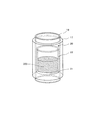
- FIG. 3 is a perspective view showing an example of the configuration of the crucible 20, the heating element 17, and the shield 18 shown in FIG. Below, the positional relationship of the crucible 20, the heat generating body 17, and the shielding body 18 is demonstrated.
- the crucible 20 is made of molybdenum.
- the crucible 20 may be substantially made of only molybdenum material or made of only tungsten (W) material.
- an alloy of molybdenum and tungsten (Mo—W), and other metal elements such as niobium and tantalum may be contained. If it is made of an alloy of molybdenum and tungsten (Mo—W), it preferably contains 10% to 40% by mass of tungsten. Any crucible 20 using these is cheaper than iridium.
- the bottom portion 21 has a circular shape and has a substantially uniform thickness (for example, about 2 mm to 7 mm) over the entire area. Further, the wall portion 22 has a cylindrical shape, and this also has a substantially uniform thickness (for example, about 2 mm to 7 mm) over the entire region.
- the inner diameter of the crucible 20 is determined by the diameter of the single crystal to be grown. For example, when growing a sapphire single crystal having a diameter of about 150 mm (about 6 inches), the inner diameter of the crucible 20 is about 220 mm.
- Heating element 17 When a part of the magnetic flux generated by the high-frequency current supplied to the heating coil 30 crosses the heating element 17 through the heat insulating container 11, the heating element 17 blocks the change of the magnetic field on the wall surface of the heating element 17. As a result, an eddy current is generated in the heating element 17.
- the heating element 17 is provided for heating and melting the raw material charged in the crucible 20, it needs to be stable at a temperature near the melting point of the raw material charged in the crucible 20.
- the melting point of alumina is about 2040 ° C.
- the temperature of the alumina melt 300 is heated from 2100 ° C. to 2400 ° C.
- Graphite has a sufficient heat resistance with a melting point of 3500 ° C. or higher. Further, graphite has an electrical resistance that efficiently induces induction heating. Therefore, in the present embodiment, graphite is used as the heating element 17.
- the heating element 17 is not limited to graphite, and may be any material that satisfies the above requirements, and is preferably a material containing carbon. Since the thickness of the heating element 17 is affected by the frequency of the high-frequency current supplied from the coil power supply 90, the thickness is preferably in the range of 5 mm to 30 mm in the present invention. If it is thicker than 30 mm, the heat generation efficiency of the heat generator 17 is lowered.
- the heating element 17 becomes too thick, a portion that does not generate heat is generated, and heat is taken away from this, so that the heating efficiency of the heating element 17 is not good.
- the thickness is less than 5 mm, the heat generation efficiency of the heat generator 17 is lowered. That is, if the heating element 17 becomes too thin, the portion that generates heat is reduced, so that the high-frequency current supplied to the heating coil 30 is less likely to be reflected in the heat generation amount.
- the thickness of the heating element 17 is preferably 10 mm to 20 mm.
- Graphite is easy to exfoliate and has a vapor pressure when heated from 2100 ° C. to 2400 ° C. And carbon particles which carbon gas and carbon gas solidified are generated.
- the generated carbon gas and carbon particles are mixed into the alumina melt 300 in the crucible 20, it is taken into the sapphire single crystal and becomes a crystal defect. Further, the carbon gas and the carbon particles reduce the alumina melt 300 to generate oxygen (O 2 ) and carbon monoxide (CO). For this reason, it reacts with molybdenum in the crucible 20 to produce molybdenum oxide rich in sublimation. Thereby, the crucible 20 corrodes and the life of the crucible 20 is shortened.
- the shield 18 is located between the outer wall portion 22 of the crucible 20 and the heating element 17, so that the constituent material of the heating element 17 (for example, carbon gas and carbon particles when the heating element 17 is graphite) is contained in the crucible 20. To be mixed into the alumina melt 300. For this reason, the shield 18 needs to be stable at a temperature near the melting point of the raw material charged into the crucible 20 and, for example, when the heating element 17 is graphite, it may not be decomposed by carbon gas and carbon particles. preferable.
- the constituent material of the heating element 17 for example, carbon gas and carbon particles when the heating element 17 is graphite
- Tantalum carbide is a carbide material with a high melting point of 3873 ° C. and stable at high temperatures. Therefore, it is not decomposed by carbon gas and carbon particles. Therefore, in this embodiment, tantalum carbide is used.
- the shield 18 is not limited to tantalum carbide, and may be any material that satisfies the above requirements, and is preferably a material containing carbide.
- the crucible 20 and the shield 18 are arranged close to each other, but are provided so as not to contact each other. Since the shield 18 is heated by heat conduction or heat radiation from the heating element 17, when the crucible 20 and the shield 18 come into contact with each other, the temperature of the contacted portion of the crucible 20 increases, and the inside of the crucible 20 The temperature gradient of the alumina melt 300 becomes steep. On the other hand, the heating element 17 and the shielding body 18 may be in contact with each other, but when the heating element 17 and the shielding body 18 are locally in contact with each other, the portion becomes high temperature. Therefore, it is preferable that the heating element 17 and the shield 18 are in close contact with each other, or are arranged close to each other without contact.
- the thickness of the shield 18 is preferably in the range of 0.1 mm to 10 mm. If the thickness is more than 10 mm, processing becomes difficult and the cost increases. On the other hand, if the thickness is less than 0.1 mm, the strength as the shield 18 becomes fragile and may be damaged when taken out from the single crystal pulling apparatus 1 (at the time of handling). Disappear.
- the thickness of the shield 18 is preferably in the range of 0.3 mm to 5 mm.
- the heating element 30 is heated by the heating coil 30, and the shield 18 disposed in close contact with or in close proximity to the heating element 17 causes the heat conduction from the heating element 17 and / or Or it is heated by thermal radiation.
- positioned in proximity to the shield 18 is heated by the thermal radiation from the heated shield 18.
- the crucible 20 serves only as a container for holding the alumina melt 300, and the heating element 17 serves as a heater. That is, the crucible 20 is indirectly heated.
- the temperature gradient of the alumina melt 300 in the crucible 20 is reduced as compared with the case where the crucible 20 also serves as a heater by induction heating. . Thereby, generation
- the length of the side surface of the heating element 17 may be shorter than the length of the wall part 22 of the crucible 20, but preferably the length of the wall part 22 of the crucible 20 or longer and the upper end of the heating element 17. It is sufficient in terms of efficiency to heat the crucible 20 that the lower end and the lower end are set so as to protrude from the upper end and the lower end of the crucible 20, respectively.
- the shield 18 is interposed between the crucible 20 and the heating element 17. However, since the heat capacity of the shield 18 is small, the shield 18 can be a sufficient heat source for heating the crucible 20. Absent. Therefore, most of the heat for heating the crucible 20 is supplied from the heating element 17.
- the length of the side surface of the cylindrical heating element 17 is shorter than the length of the wall portion 22 of the crucible 20 (height of the crucible 20), heat is generated in the upper part or / and the lower part of the wall portion 22 of the crucible 20. Sufficient heat radiation from the body 17 (including the shield 18) cannot be received, and a steep temperature gradient may be generated in the crucible 20 or the alumina melt 300.
- the shield 18 is provided to prevent the constituent material of the heating element 17 (for example, when the heating element 17 is graphite, carbon gas and carbon particles) from being mixed into the crucible 20.
- the upper end of the shield 18 is set higher than the upper end of the heating element 17. That is, the upper end of the shield 18 is preferably higher than the upper end of the heating element 17.
- the upper end of the shield 18 may be lower than the upper end of the wall portion 22 of the crucible 20, but it is more preferable that the upper end of the wall portion 22 of the crucible 20 be provided at a height higher than that.
- the lower end of the shield 18 may be at least within the range of the wall portion 22 of the crucible 20, and may be set lower than the lower end of the wall portion 22 of the crucible 20.
- the lower end of the shield 18 only needs to be within the range of the side surface of the heating element 17, and may be set lower than the lower end of the heating element 17. That is, the shield 18 is provided so as to separate the crucible 20 and the heating element 17 in the opening portion of the crucible 20 provided vertically upward. This is because the constituent material of the heating element 17 is mixed into the alumina melt 300 in the crucible 20 through the opening of the crucible 20 provided vertically upward. This is because it is sufficient that the shield 18 can suppress the mixing of the constituent materials of the heating element 17.
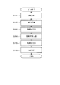
- FIG. 4 is a flowchart for explaining an example of a procedure for manufacturing the sapphire ingot 200 shown in FIG. 2 using the single crystal pulling apparatus 1 shown in FIG.
- a melting step is performed in which solid aluminum oxide filled in the crucible 20 in the chamber 14 is melted by heating (step 101).
- a seeding step is performed in which temperature adjustment is performed in a state where the lower end portion of the seed crystal 210 is in contact with the aluminum oxide melt, that is, the alumina melt 300 (step 102).
- the shoulder 220 is formed below the seed crystal 210 by pulling it upward (in the direction of arrow A in FIG.
- a shoulder forming step is executed (step 103). Subsequently, a straight body part forming step is performed in which the straight body part 230 is formed below the shoulder part 220 by pulling upward through the seed crystal 210 while rotating the shoulder part 220 (step 104). Further, the tail forming step of forming the tail 240 below the straight body 230 by pulling up and separating from the alumina melt 300 while rotating the straight body 230 through the seed crystal 210 and the shoulder 220. Is executed (step 105).
- step 106 the cooling process which stops and cools the heating of the alumina melt 300 in the crucible 20 is executed (step 106), and after the obtained sapphire ingot 200 is cooled, it is taken out of the chamber 14 and a series of manufacturing is performed. Complete the process.
- the sapphire ingot 200 thus obtained is first cut at the boundary between the shoulder 220 and the straight body 230 and at the boundary between the straight body 230 and the tail 240, and the straight body 230 is cut out. .
- the cut out straight body portion 230 is further cut in a direction orthogonal to the longitudinal direction to form a sapphire single crystal wafer.
- the main surface of the obtained wafer is the c-plane ((0001) plane).
- the obtained wafer is used for manufacturing blue LEDs and polarizers.
- a c-axis ( ⁇ 0001>) seed crystal 210 is prepared.
- the seed crystal 210 is attached to the holding member 41 of the pulling rod 40 and set at a predetermined position.
- the crucible 20 is filled with a raw material of aluminum oxide, that is, an alumina raw material, the crucible 20 is placed on the crucible support 15, and the heat insulating container 11 is assembled in the chamber 14.
- the inside of the chamber 14 is decompressed using the exhaust unit 80 in a state where the gas supply from the gas supply unit 70 is not performed.
- the gas supply unit 70 supplies a predetermined gas into the chamber 14 to bring the inside of the chamber 14 to normal pressure.
- the gas supply unit 70 supplies a predetermined gas into the chamber 14.
- the gas supplied in the melting step may be the same as or different from that in the preparation step.
- the rotation driving unit 60 rotates the pulling rod 40 at the first rotation speed.
- the coil power supply 90 supplies a high frequency current to the heating coil 30.
- a high frequency current is supplied from the coil power supply 90 to the heating coil 30, the magnetic flux repeatedly generates and disappears around the heating coil 30.
- the crucible 20 when the bottom 21 and the wall 22 of the crucible 20 are heated and the aluminum oxide accommodated in the crucible 20 is heated beyond its melting point (2054 ° C.), the crucible 20 The alumina raw material, that is, aluminum oxide is melted to form an alumina melt 300.
- the gas supply unit 70 supplies a predetermined gas into the chamber 14.
- the gas supplied in the seeding step may be the same as or different from that in the melting step. However, as in the melting step, mixing of oxygen is not preferable.
- the pulling drive unit 50 lowers the pulling rod 40 to a position where the lower end of the seed crystal 210 attached to the holding member 41 comes into contact with the alumina melt 300 in the crucible 20 and stops it. In this state, the coil power supply 90 adjusts the current value of the high-frequency current supplied to the heating coil 30 based on the weight signal from the weight detection unit 110.
- the shoulder forming step the high frequency current supplied from the coil power supply 90 to the heating coil 30 is adjusted, and then held for a while until the temperature of the alumina melt 300 is stabilized, and then the lifting rod 40 is moved to the first rotational speed. Pull up at the first pulling speed while rotating.
- the seed crystal 210 is pulled up while being rotated with its lower end immersed in the alumina melt 300, and a shoulder 220 that expands vertically downward is formed at the lower end of the seed crystal 210. It will be done. Note that the shoulder forming step is completed when the diameter of the shoulder 220 becomes about several mm larger than the desired diameter of the wafer.
- the gas supply unit 70 supplies a predetermined gas into the chamber 14.
- the gas supplied in a straight body part formation process may be the same as a shoulder part formation process, and may differ. However, as in the melting step, mixing of oxygen is not preferable.
- the coil power supply 90 continues to supply a high frequency current to the heating coil 30 to heat the alumina melt 300 through the crucible 20.
- the pulling drive unit 50 pulls the pulling rod 40 at the second pulling speed.
- the second pulling speed may be the same as or different from the first pulling speed in the shoulder forming step.
- the rotation drive unit 60 rotates the pulling rod 40 at the second rotation speed.
- the second rotation speed may be the same speed as the first rotation speed in the shoulder forming step, or may be a different speed.
- the shoulder 220 integrated with the seed crystal 210 is pulled up while being rotated while the lower end of the shoulder 220 is immersed in the alumina melt 300.
- the trunk portion 230 is formed.
- the diameter of the straight body 230 may be equal to or larger than the desired diameter of the wafer.
- the gas supply unit 70 supplies a predetermined gas into the chamber 14.
- the gas supplied in the tail portion forming step may be the same as or different from that in the straight body portion forming step.
- mixing of oxygen is not preferable.
- the coil power supply 90 continues to supply a high-frequency current to the heating coil 30 to heat the alumina melt 300 through the crucible 20.
- the pulling drive unit 50 pulls the pulling rod 40 at the third pulling speed.
- the third pulling speed may be the same as the first pulling speed in the shoulder forming process or the second pulling speed in the straight body forming process, or may be a speed different from these. Good.
- the rotation drive unit 60 rotates the pulling rod 40 at the third rotation speed.
- the third rotation speed may be the same as the first rotation speed in the shoulder forming process or the second rotation speed in the straight body forming process, or may be different from these. Also good.
- the pulling drive unit 50 increases the pulling speed of the pulling bar 40 and pulls the pulling bar 40 further upward, thereby lowering the lower end of the tail 240. Pull away from melt 300. Thereby, the sapphire ingot 200 shown in FIG. 2 is obtained.
- the gas supply unit 70 supplies a predetermined gas into the chamber 14.
- the gas supplied in the cooling step may be the same as or different from the tail forming step.
- mixing of oxygen is not preferable.
- the coil power supply 90 stops the supply of the high-frequency current to the heating coil 30 and stops the heating of the alumina melt 300 through the crucible 20.
- the pulling drive unit 50 stops the pulling of the pulling rod 40 and the rotation driving unit 60 stops the rotation of the pulling rod 40. At this time, a small amount of aluminum oxide that did not form the sapphire ingot 200 remains as the alumina melt 300 in the crucible 20.
- the alumina melt 300 in the crucible 20 with the stop of heating is gradually cooled and solidified in the crucible 20 after falling below the melting point of aluminum oxide to become aluminum oxide solid. Then, the sapphire ingot 200 is taken out from the chamber 14 with the chamber 14 sufficiently cooled.
- the crucible 20 is indirectly heated without directly heating the wall portion 22 of the crucible 20 by the heating coil 30. For this reason, compared with the case where the wall part 22 of the crucible 20 is directly heated with the heating coil 30, the temperature gradient of the melt in the crucible 20 can be relieved. Therefore, distortion generated in the single crystal grown by the rapid temperature gradient can be suppressed.
Landscapes
- Chemical & Material Sciences (AREA)
- Engineering & Computer Science (AREA)
- Crystallography & Structural Chemistry (AREA)
- Materials Engineering (AREA)
- Metallurgy (AREA)
- Organic Chemistry (AREA)
- Inorganic Chemistry (AREA)
- Crystals, And After-Treatments Of Crystals (AREA)
Abstract
単結晶引き上げ装置1は、サファイア単結晶からなるサファイアインゴット200を成長させるための加熱炉10を有している。断熱容器11の内側下方には、アルミナ融液300を収容するるつぼ20が配置されている。断熱容器11の内側且つるつぼ20の外側にあって、るつぼ20の壁部22を取り巻くように設けられた発熱体17を備えている。そして、発熱体17の内側且つるつぼ20の外側にあって、るつぼ20の壁部22を取り巻くように設けられ、発熱体17の構成材料がるつぼ20内のアルミナ融液300に混入するのを防止する遮蔽体18を備えている。このように、チョクラルスキー(Cz)法による単結晶引き上げ装置において、安価なるつぼの使用を可能とするとともに、るつぼ内の融液の温度勾配を緩くして、成長させた単結晶の歪みを抑制する。
Description
本発明は、融液から単結晶を引き上げて成長させる単結晶引き上げ装置に関する。
チョクラルスキー法(Cz法)を用いた単結晶引き上げ装置では、るつぼ内に収容され、るつぼを介して加熱される原料融液から、目的とする材料の単結晶の引き上げを行っている。
例えば、Cz法により単結晶を製造するには、まずるつぼに原料を充填し、高周波加熱法や抵抗加熱法によりるつぼを加熱し原料を溶解する。原料が溶解して原料融液となったところで、予め定められた結晶方位に切り出された種結晶を原料融液表面に接触させ、種結晶を予め定められた回転速度で回転させながら予め定められた速度で引き上げることで単結晶を成長させる。
このとき、イリジウム製のるつぼが多く用いられていた。しかし、イリジウム製のるつぼは高価であって、単結晶の製造コストを押し上げる要因になっていた。そこで、るつぼをイリジウムに比べ1/20程度と価格の低いモリブデン(Mo)製等にすることが提案されている。
例えば、Cz法により単結晶を製造するには、まずるつぼに原料を充填し、高周波加熱法や抵抗加熱法によりるつぼを加熱し原料を溶解する。原料が溶解して原料融液となったところで、予め定められた結晶方位に切り出された種結晶を原料融液表面に接触させ、種結晶を予め定められた回転速度で回転させながら予め定められた速度で引き上げることで単結晶を成長させる。
このとき、イリジウム製のるつぼが多く用いられていた。しかし、イリジウム製のるつぼは高価であって、単結晶の製造コストを押し上げる要因になっていた。そこで、るつぼをイリジウムに比べ1/20程度と価格の低いモリブデン(Mo)製等にすることが提案されている。
特許文献1には、チャンバー内にMo製ルツボが設置され、該ルツボの外周には、筒状のカーボン製ヒータ及びカーボン製保温体が設置された単結晶サファイア引上装置が記載されている。
特許文献2には、るつぼに価格の低いモリブデン(Mo)又はタングステン(W)を用い、加熱室形成部材としてカーボンフェルト成形品及びカーボンフェルトが使用できるようにしたサファイア単結晶引上成長装置が記載されている。
特許文献3には、イリジウム製ルツボ(B)の内側に、モリブデン製又はタングステン製ルツボ(A)を互いに接触しないように設置して二重構造とし、ルツボ(B)を高温に加熱し、その輻射熱でルツボ(A)を間接的に加熱することで、ルツボ(A)に熱的ダメージを与えることなく、効率的に原料粉末を溶融でき、比較的安価なモリブデン製又はタングステン製ルツボ(A)を用いてもインクルージョンのない高品質なサファイア単結晶を成長させうるサファイア単結晶育成装置が記載されている。
特許文献2には、るつぼに価格の低いモリブデン(Mo)又はタングステン(W)を用い、加熱室形成部材としてカーボンフェルト成形品及びカーボンフェルトが使用できるようにしたサファイア単結晶引上成長装置が記載されている。
特許文献3には、イリジウム製ルツボ(B)の内側に、モリブデン製又はタングステン製ルツボ(A)を互いに接触しないように設置して二重構造とし、ルツボ(B)を高温に加熱し、その輻射熱でルツボ(A)を間接的に加熱することで、ルツボ(A)に熱的ダメージを与えることなく、効率的に原料粉末を溶融でき、比較的安価なモリブデン製又はタングステン製ルツボ(A)を用いてもインクルージョンのない高品質なサファイア単結晶を成長させうるサファイア単結晶育成装置が記載されている。
ところで、高周波加熱法を用いたCz法では、るつぼは、原料融液を保持する容器としての役割と、るつぼ自体が発熱して原料を溶解するヒータとしての役割とを兼ねている。このため、るつぼには、発熱した部分と発熱していない部分とが混在することになり、るつぼ内の融液の温度勾配が急峻になってしまっていた。このため、成長させた単結晶に歪みが生じてしまっていた。
そこで、特許文献3にあるように、るつぼを二重構造にし、間接的に加熱することが提案されている。しかし、特許文献3では、高価なイリジウム製のるつぼの使用を必要としていた。
本発明は、チョクラルスキー(Cz)法による単結晶引き上げ装置において、安価なるつぼの使用を可能とするとともに、るつぼ内の融液の温度勾配を緩くして、成長させた単結晶の歪みを抑制することを目的とする。
そこで、特許文献3にあるように、るつぼを二重構造にし、間接的に加熱することが提案されている。しかし、特許文献3では、高価なイリジウム製のるつぼの使用を必要としていた。
本発明は、チョクラルスキー(Cz)法による単結晶引き上げ装置において、安価なるつぼの使用を可能とするとともに、るつぼ内の融液の温度勾配を緩くして、成長させた単結晶の歪みを抑制することを目的とする。
本発明が適用される単結晶引き上げ装置は、底部および底部の周縁から立ち上がる壁部を有し、原料融液を収容するるつぼと、るつぼと近接するが接触せずにるつぼを包囲するように設けられた第1の筒状部材と、第1の筒状部材を包囲するように設けられた炭素または炭素を含む材料から構成される第2の筒状部材と、第2の筒状部材の外側に巻き回され、交流電流の供給によって第2の筒状部材を誘導加熱するコイルと、るつぼの上方に配置され、るつぼに収容される原料融液から柱状の単結晶を引き上げる引き上げ部材とを含んでいる。
そして、るつぼは、モリブデン(Mo)、モリブデン(Mo)を含む合金、タングステン(W)、あるいはタングステン(W)を含む合金で構成されることを特徴とすることができる。
また、第1の筒状部材は、タンタル(Ta)、タングステン(W)、またはこれらのうち少なくとも一種の元素の炭化物で構成されることを特徴とすることができる。
さらに、第2の筒状部材は、グラファイトで構成されることを特徴とすることができる。
そして、るつぼは、モリブデン(Mo)、モリブデン(Mo)を含む合金、タングステン(W)、あるいはタングステン(W)を含む合金で構成されることを特徴とすることができる。
また、第1の筒状部材は、タンタル(Ta)、タングステン(W)、またはこれらのうち少なくとも一種の元素の炭化物で構成されることを特徴とすることができる。
さらに、第2の筒状部材は、グラファイトで構成されることを特徴とすることができる。
このような単結晶引き上げ装置において、るつぼは、原料融液としてアルミナ融液を収容し、引き上げ部材は、るつぼに収容されたアルミナ融液から柱状のサファイア単結晶を引き上げることを特徴とすることができる。
さらにまた、引き上げ部材は、るつぼに収容されたアルミナ融液からc軸方向に成長させた柱状のサファイア単結晶を引き上げることを特徴とすることができる。
さらにまた、引き上げ部材は、るつぼに収容されたアルミナ融液からc軸方向に成長させた柱状のサファイア単結晶を引き上げることを特徴とすることができる。
本発明によれば、チョクラルスキー(Cz)法による単結晶引き上げ装置において、安価なるつぼの使用を可能とするとともに、るつぼ内の融液の温度勾配を緩くすることができるので、成長させた単結晶の歪みが抑制できる。
以下、添付図面を参照して、本発明の実施の形態について詳細に説明する。
(単結晶引き上げ装置1)
図1は、本実施の形態が適用される単結晶引き上げ装置1の構成の一例を説明するための図である。
この単結晶引き上げ装置1は、柱状の単結晶の一例としてのサファイア単結晶からなるサファイアインゴット200を成長させるための加熱炉10を有している。この加熱炉10は、円柱状の外形を有し、その内部には円柱状の空間が形成された断熱容器11を備えている。そして、断熱容器11は、ジルコニア製の断熱材からなる部品を組み立てることで構成されている。また、加熱炉10は、内部の空間に断熱容器11を収容するチャンバ14をさらに備えている。さらに、加熱炉10は、チャンバ14の側面に貫通形成され、チャンバ14の外部からチャンバ14を介して断熱容器11の内部にガスを供給するガス供給管12と、同じくチャンバ14の側面に貫通形成され、断熱容器11の内部からチャンバ14を介して外部にガスを排出するガス排出管13とを備えている。
(単結晶引き上げ装置1)
図1は、本実施の形態が適用される単結晶引き上げ装置1の構成の一例を説明するための図である。
この単結晶引き上げ装置1は、柱状の単結晶の一例としてのサファイア単結晶からなるサファイアインゴット200を成長させるための加熱炉10を有している。この加熱炉10は、円柱状の外形を有し、その内部には円柱状の空間が形成された断熱容器11を備えている。そして、断熱容器11は、ジルコニア製の断熱材からなる部品を組み立てることで構成されている。また、加熱炉10は、内部の空間に断熱容器11を収容するチャンバ14をさらに備えている。さらに、加熱炉10は、チャンバ14の側面に貫通形成され、チャンバ14の外部からチャンバ14を介して断熱容器11の内部にガスを供給するガス供給管12と、同じくチャンバ14の側面に貫通形成され、断熱容器11の内部からチャンバ14を介して外部にガスを排出するガス排出管13とを備えている。
断熱容器11の内側下方には、酸化アルミニウム(Al2O3)を溶融してなる原料融液の一例としてのアルミナ融液300を収容するるつぼ20が配置されている。るつぼ20は、鉛直上方に向かって開口する形状を有している。このるつぼ20は、底部21と、底部21の周縁から上方に立ち上がる壁部22とを有している。るつぼ20は、例えばモリブデン(Mo)製である。
また、断熱容器11の内側下方且つるつぼ20の底部21の下には、円板状の外形を有するるつぼ支持台15が配置されている。このるつぼ支持台15は、るつぼ20と同様にモリブデン製であってよい。そして、このるつぼ支持台15は、断熱容器11の内側底面からシャフト16によって支持されている。このシャフト16も、るつぼ20およびるつぼ支持台15と同様にモリブデン製であってよい。このように、るつぼ20はるつぼ支持台15およびシャフト16によって、断熱容器11の内側底面から支持されている。
さらに、断熱容器11の内側且つるつぼ20の外側にあって、るつぼ20の壁部22を取り巻くように設けられた、第2の筒状部材の一例としての発熱体17を備えている。発熱体17は、例えばグラファイト(黒鉛)等のカーボン(炭素)製である。
そして、発熱体17の内側且つるつぼ20の外側にあって、るつぼ20の壁部22を取り巻くように設けられ、発熱体17の構成材料が、るつぼ20内のアルミナ融液300に混入するのを防止する第1の筒状部材の一例としての遮蔽体18を備えている。遮蔽体18の構成材料としては、例えば金属のタンタル(Ta)、金属のタングステン(W)、またはこれらのうち少なくとも一種の元素の炭化物が挙げられる。中でも、遮蔽体18は炭化タンタル(タンタルカーバイド:TaC)製であることが好ましい。
すなわち、るつぼ20の外側の側面は、筒状の遮蔽体18と、さらにその遮蔽体18の外側に設けられた発熱体17とで取り囲まれている。
そして、発熱体17の内側且つるつぼ20の外側にあって、るつぼ20の壁部22を取り巻くように設けられ、発熱体17の構成材料が、るつぼ20内のアルミナ融液300に混入するのを防止する第1の筒状部材の一例としての遮蔽体18を備えている。遮蔽体18の構成材料としては、例えば金属のタンタル(Ta)、金属のタングステン(W)、またはこれらのうち少なくとも一種の元素の炭化物が挙げられる。中でも、遮蔽体18は炭化タンタル(タンタルカーバイド:TaC)製であることが好ましい。
すなわち、るつぼ20の外側の側面は、筒状の遮蔽体18と、さらにその遮蔽体18の外側に設けられた発熱体17とで取り囲まれている。
なお、るつぼ20と遮蔽体18とは、近接して配置されるが、接触しないように設けられている。一方、発熱体17と遮蔽体18とは、密着して設けられている。なお、発熱体17と遮蔽体18とは、それぞれ部材により断熱容器11の内側底面または内側上面から固定されている(不図示)。
るつぼ20、遮蔽体18、発熱体17については、後に詳述する。
るつぼ20、遮蔽体18、発熱体17については、後に詳述する。
さらに、加熱炉10は、断熱容器11の下部側の側面外側であってチャンバ14の下部側の側面内側となる部位に巻き回された金属製の加熱コイル30を備えている。この加熱コイル30は、断熱容器11を介して発熱体17の側面と対向するように配置されている。
加熱コイル30は、例えば中空状の銅管によって構成されている。また、加熱コイル30は螺旋状に巻き回されており、全体としてみたときに円筒状の形状を有している。すなわち、加熱コイル30の上部側の内径と下部側の内径とがほぼ同一になっている。これにより、巻き回された加熱コイル30によってその内部に形成される空間が円柱状となっている。また、円柱状の空間を通る加熱コイル30の中心軸は、水平方向に対しほぼ垂直すなわち鉛直方向に沿うようになっている。
加熱コイル30は、例えば中空状の銅管によって構成されている。また、加熱コイル30は螺旋状に巻き回されており、全体としてみたときに円筒状の形状を有している。すなわち、加熱コイル30の上部側の内径と下部側の内径とがほぼ同一になっている。これにより、巻き回された加熱コイル30によってその内部に形成される空間が円柱状となっている。また、円柱状の空間を通る加熱コイル30の中心軸は、水平方向に対しほぼ垂直すなわち鉛直方向に沿うようになっている。
さらにまた、加熱炉10は、断熱容器11、チャンバ14それぞれの上面に設けられた貫通孔を介して上方から下方に伸びる引き上げ部材の一例としての引き上げ棒40を備えている。この引き上げ棒40は、鉛直方向への移動および軸を中心とする回転が可能となるように取り付けられている。なお、チャンバ14に設けられた貫通孔と引き上げ棒40との間には、不図示のシール材が設けられている。そして、引き上げ棒40の鉛直下方側の端部には、サファイアインゴット200を成長させるための基となる種結晶210(後述する図2参照)を装着、保持させるための保持部材41が取り付けられている。
また、単結晶引き上げ装置1は、引き上げ棒40を鉛直上方(矢印A方向)に引き上げるための引き上げ駆動部50および引き上げ棒40を矢印B方向へ回転させるための回転駆動部60を備えている。ここで、引き上げ駆動部50はモータ等で構成されており、引き上げ棒40の矢印A方向への引き上げ速度を調整できるようになっている。また、回転駆動部60もモータ等で構成されており、引き上げ棒40の矢印B方向への回転速度を調整できるようになっている。
さらに、単結晶引き上げ装置1は、ガス供給管12を介してチャンバ14の内部にガスを供給するガス供給部70を備えている。本実施の形態において、ガス供給部70は、例えば窒素、アルゴン等の不活性ガスを供給することができる。そして、ガス供給部70は、チャンバ14の内部に供給するガスの流量を調整することも可能となっている。
一方、単結晶引き上げ装置1は、ガス排出管13を介してチャンバ14の内部からガスを排出する排気部80を備えている。排気部80は例えば真空ポンプ等を備えており、チャンバ14内の減圧や、ガス供給部70から供給されたガスの排気をすることが可能となっている。
さらにまた、単結晶引き上げ装置1は、加熱コイル30に高周波の交流電流(以下の説明では高周波電流と呼ぶ。)を供給するコイル電源90を備えている。コイル電源90は、加熱コイル30への高周波電流の供給の有無および供給する電流量、さらには加熱コイル30に供給する高周波電流の周波数を設定できるようになっている。
また、単結晶引き上げ装置1は、引き上げ棒40を介して引き上げ棒40の下部側に成長するサファイアインゴット200の重量を検出する重量検出部110を備えている。この重量検出部110は、例えば従来公知のロードセル等を含んで構成される。
そして、単結晶引き上げ装置1は、上述した引き上げ駆動部50、回転駆動部60、ガス供給部70、排気部80およびコイル電源90の動作を制御する制御部100を備えている。また、制御部100は、重量検出部110から出力される重量信号に基づき、引き上げられるサファイアインゴット200の結晶直径の計算を行い、コイル電源90にフィードバックする。
(サファイアインゴット200)
図2は、図1に示す単結晶引き上げ装置1を用いて製造されるサファイアインゴット200の構成の一例を示す図である。
このサファイアインゴット200は、サファイアインゴット200を成長させるための基となる種結晶210と、種結晶210の下部に延在しこの種結晶210と一体化した肩部220と、肩部220の下部に延在し肩部220と一体化した直胴部230と、直胴部230の下部に延在し直胴部230と一体化した尾部240とを備えている。そして、このサファイアインゴット200においては、上方すなわち種結晶210側から下方すなわち尾部240側に向けてc軸方向にサファイアの単結晶が成長している。
図2は、図1に示す単結晶引き上げ装置1を用いて製造されるサファイアインゴット200の構成の一例を示す図である。
このサファイアインゴット200は、サファイアインゴット200を成長させるための基となる種結晶210と、種結晶210の下部に延在しこの種結晶210と一体化した肩部220と、肩部220の下部に延在し肩部220と一体化した直胴部230と、直胴部230の下部に延在し直胴部230と一体化した尾部240とを備えている。そして、このサファイアインゴット200においては、上方すなわち種結晶210側から下方すなわち尾部240側に向けてc軸方向にサファイアの単結晶が成長している。
ここで、肩部220は、種結晶210側から直胴部230側に向けて、徐々にその直径が拡大していく形状を有している。また、直胴部230は、上方から下方に向けてその直径がほぼ同じとなるような形状を有している。なお、直胴部230の直径は、所望するサファイア単結晶のウエハの直径よりもわずかに大きな値に設定される。そして、尾部240は、上方から下方に向けて徐々にその直径が縮小していくことにより、上方から下方に向けて凸状となる形状を有している。なお、図2には、尾部240が直胴部230の下方に突出する凸状の形状を有している例を示しているが、製造条件を異ならせた場合には、図2に破線で示すように直胴部230の下方において窪む凹状の形状を有していることもある。
なお、本実施の形態において、c軸方向に結晶成長させたサファイアインゴット200を製造しているのは、次の理由による。
一般的に、青色LEDの基板材料や液晶プロジェクタの偏光子の保持部材等では、サファイア単結晶のc軸に垂直な面((0001)面)が主面となるように、インゴットから切り出されたウエハが用いられることが多い。したがって、歩留まりの観点からすれば、c軸方向に結晶成長させたサファイア単結晶のインゴットをウエハの切り出しに用いることが好ましい。このため、本実施の形態では、このような後工程での利便性を考慮し、c軸方向に結晶成長させたサファイアインゴット200の製造を行っている。
一般的に、青色LEDの基板材料や液晶プロジェクタの偏光子の保持部材等では、サファイア単結晶のc軸に垂直な面((0001)面)が主面となるように、インゴットから切り出されたウエハが用いられることが多い。したがって、歩留まりの観点からすれば、c軸方向に結晶成長させたサファイア単結晶のインゴットをウエハの切り出しに用いることが好ましい。このため、本実施の形態では、このような後工程での利便性を考慮し、c軸方向に結晶成長させたサファイアインゴット200の製造を行っている。
ただし、図1に示す単結晶引き上げ装置1は、c軸方向に結晶成長させたサファイアインゴット200だけでなく、例えばa軸方向に結晶成長させたサファイアインゴット200を引き上げることも可能である。また、サファイアに限らず、各種の酸化物単結晶を引き上げることも可能であり、さらには酸化物以外の単結晶を引き上げることも可能である。
(るつぼ20、発熱体17および遮蔽体18)
図3は、図1に示するつぼ20、発熱体17および遮蔽体18の構成の一例を示す斜視図である。
以下では、るつぼ20、発熱体17および遮蔽体18の位置関係を説明する。
図3は、図1に示するつぼ20、発熱体17および遮蔽体18の構成の一例を示す斜視図である。
以下では、るつぼ20、発熱体17および遮蔽体18の位置関係を説明する。
<るつぼ20>
最初に、るつぼ20の構成について説明する。
本実施の形態では、るつぼ20はモリブデンによって構成されている。るつぼ20は、実質的にモリブデン材料のみからなるもの、あるいはタングステン(W)材料のみからなるものでよい。この他に、モリブデンとタングステンとの合金(Mo-W)、さらにはニオブ、タンタルなど他の金属元素を含有するものであってもよい。モリブデンとタングステンとの合金(Mo-W)製であれば、タングステンを10質量%~40質量%含有するものが好ましい。これらを用いたるつぼ20は、いずれであっても、イリジウム製に比べ安価である。
最初に、るつぼ20の構成について説明する。
本実施の形態では、るつぼ20はモリブデンによって構成されている。るつぼ20は、実質的にモリブデン材料のみからなるもの、あるいはタングステン(W)材料のみからなるものでよい。この他に、モリブデンとタングステンとの合金(Mo-W)、さらにはニオブ、タンタルなど他の金属元素を含有するものであってもよい。モリブデンとタングステンとの合金(Mo-W)製であれば、タングステンを10質量%~40質量%含有するものが好ましい。これらを用いたるつぼ20は、いずれであっても、イリジウム製に比べ安価である。
底部21は円形状を有しており、全域にわたってほぼ均一な厚さ(例えば2mm~7mm程度)となっている。また、壁部22は円筒形状を有しており、こちらも全域にわたってほぼ均一な厚さ(例えば2mm~7mm程度)となっている。
なお、るつぼ20の内径は、成長させようとする単結晶の直径で決まる。例えば、直径約150mm(約6インチ)のサファイア単結晶を育成する場合には、るつぼ20の内径は、約220mmである。
なお、るつぼ20の内径は、成長させようとする単結晶の直径で決まる。例えば、直径約150mm(約6インチ)のサファイア単結晶を育成する場合には、るつぼ20の内径は、約220mmである。
<発熱体17>
次に、発熱体17について説明する。発熱体17は、加熱コイル30に供給された高周波電流によって生じた磁束の一部が、断熱容器11を介して発熱体17を横切ると、発熱体17の壁面にはその磁界の変化をさまたげるような磁界が発生し、結果として発熱体17内には渦電流が発生する。そして、発熱体17には、渦電流(I)によって発熱体17の表皮抵抗(R)に比例したジュール熱(W=I2R)が発生し、発熱体17が発熱する(誘導加熱)。よって、発熱体17は、電気抵抗がある程度高いことが好ましい。
また、発熱体17は、るつぼ20に投入された原料を加熱溶解するために設けられているので、るつぼ20に投入された原料の融点付近の温度において安定であることを要する。例えば、アルミナの融点は2040℃程度であって、アルミナ融液300の温度は2100℃から2400℃に加熱される。
次に、発熱体17について説明する。発熱体17は、加熱コイル30に供給された高周波電流によって生じた磁束の一部が、断熱容器11を介して発熱体17を横切ると、発熱体17の壁面にはその磁界の変化をさまたげるような磁界が発生し、結果として発熱体17内には渦電流が発生する。そして、発熱体17には、渦電流(I)によって発熱体17の表皮抵抗(R)に比例したジュール熱(W=I2R)が発生し、発熱体17が発熱する(誘導加熱)。よって、発熱体17は、電気抵抗がある程度高いことが好ましい。
また、発熱体17は、るつぼ20に投入された原料を加熱溶解するために設けられているので、るつぼ20に投入された原料の融点付近の温度において安定であることを要する。例えば、アルミナの融点は2040℃程度であって、アルミナ融液300の温度は2100℃から2400℃に加熱される。
グラファイトは融点が3500℃以上と十分な耐熱性を有している。さらに、グラファイトは効率よく誘導加熱を生じる電気抵抗を有している。
よって、本実施の形態では、グラファイトを発熱体17として用いている。なお、発熱体17は、グラファイトに限らず、上記要件を満たすものであればよく、カーボン(炭素)を含む材料であることが好ましい。
発熱体17の厚さは、コイル電源90から供給される高周波電流の周波数に影響を受けるので、本発明においては5mm~30mmの範囲がよい。30mmよりも厚すぎると発熱体17による発熱効率が低下する。すなわち、発熱体17が厚くなりすぎると発熱しない部分が生じ、これに熱が奪われるため、発熱体17の発熱効率がよくない。また、5mmよりも薄すぎると、発熱体17による発熱効率が低下する。すなわち、発熱体17が薄くなりすぎると発熱する部分が少なくなるので加熱コイル30に供給された高周波電流が発熱量に反映しにくくなる。発熱体17の厚さは、好ましくは10mm~20mmである。
よって、本実施の形態では、グラファイトを発熱体17として用いている。なお、発熱体17は、グラファイトに限らず、上記要件を満たすものであればよく、カーボン(炭素)を含む材料であることが好ましい。
発熱体17の厚さは、コイル電源90から供給される高周波電流の周波数に影響を受けるので、本発明においては5mm~30mmの範囲がよい。30mmよりも厚すぎると発熱体17による発熱効率が低下する。すなわち、発熱体17が厚くなりすぎると発熱しない部分が生じ、これに熱が奪われるため、発熱体17の発熱効率がよくない。また、5mmよりも薄すぎると、発熱体17による発熱効率が低下する。すなわち、発熱体17が薄くなりすぎると発熱する部分が少なくなるので加熱コイル30に供給された高周波電流が発熱量に反映しにくくなる。発熱体17の厚さは、好ましくは10mm~20mmである。
なお、グラファイトは、剥離しやすいと共に、上記2100℃から2400℃に加熱されると、蒸気圧を持つようになる。そして、カーボンガス及びカーボンガスが固化したカーボン粒子が発生する。この発生したカーボンガス及びカーボン粒子がるつぼ20内のアルミナ融液300に混入すると、サファイア単結晶に取り込まれ、結晶欠陥となってしまう。また、カーボンガス及びカーボン粒子は、アルミナ融液300を還元して、酸素(O2)や一酸化炭素(CO)を生成する。このため、るつぼ20のモリブデンと反応し、昇華性に富むモリブデンの酸化物を生成する。これにより、るつぼ20が腐食し、るつぼ20の寿命を短くしてしまう。
<遮蔽体18>
遮蔽体18は、るつぼ20の外側の壁部22と発熱体17との間にあって、発熱体17構成材料(例えば、発熱体17がグラファイトの場合にはカーボンガス及びカーボン粒子)が、るつぼ20内のアルミナ融液300に混入するのを防止する。このため、遮蔽体18は、るつぼ20に投入された原料の融点付近の温度において安定であることを要するとともに、例えば、発熱体17がグラファイトの場合にはカーボンガス及びカーボン粒子により分解されないことが好ましい。
遮蔽体18は、るつぼ20の外側の壁部22と発熱体17との間にあって、発熱体17構成材料(例えば、発熱体17がグラファイトの場合にはカーボンガス及びカーボン粒子)が、るつぼ20内のアルミナ融液300に混入するのを防止する。このため、遮蔽体18は、るつぼ20に投入された原料の融点付近の温度において安定であることを要するとともに、例えば、発熱体17がグラファイトの場合にはカーボンガス及びカーボン粒子により分解されないことが好ましい。
炭化タンタルは、融点が3873℃と高く、高温で安定した炭化物材料である。よって、カーボンガス及びカーボン粒子により分解することがない。そこで、本実施の形態では、炭化タンタルを用いている。なお、遮蔽体18は、炭化タンタルに限らず、上記要件を満たすものであればよく、炭化物を含む材料であることが好ましい。
るつぼ20と遮蔽体18とは、近接して配置されるが、接触しないように設けられている。遮蔽体18は、発熱体17からの熱伝導または熱輻射により加熱されているので、るつぼ20と遮蔽体18とが接触すると、るつぼ20の接触した部分の温度が高くなって、るつぼ20内のアルミナ融液300の温度勾配が急峻になってしまう。
一方、発熱体17と遮蔽体18とは、接触していてもかまわないが、局部的に発熱体17と遮蔽体18とが接触すると、その部分が高温になってしまう。そこで、発熱体17と遮蔽体18と密着させるか、接触しないで近接して配置することが好ましい。
遮蔽体18の厚さは、0.1mm~10mmの範囲がよい。厚さが10mmよりも厚すぎると、加工し難くなりまたコストアップとなる。また、厚さが0.1mmよりも薄すぎると、遮蔽体18としての強度が脆くなり単結晶引き上げ装置1内からの取出し時(ハンドリング時)に破損するおそれがあり、強度面の信頼性がなくなる。遮蔽体18の厚さは、好ましくは0.3mm~5mmの範囲である。
一方、発熱体17と遮蔽体18とは、接触していてもかまわないが、局部的に発熱体17と遮蔽体18とが接触すると、その部分が高温になってしまう。そこで、発熱体17と遮蔽体18と密着させるか、接触しないで近接して配置することが好ましい。
遮蔽体18の厚さは、0.1mm~10mmの範囲がよい。厚さが10mmよりも厚すぎると、加工し難くなりまたコストアップとなる。また、厚さが0.1mmよりも薄すぎると、遮蔽体18としての強度が脆くなり単結晶引き上げ装置1内からの取出し時(ハンドリング時)に破損するおそれがあり、強度面の信頼性がなくなる。遮蔽体18の厚さは、好ましくは0.3mm~5mmの範囲である。
以上説明したように、本実施の形態では、加熱コイル30によって、発熱体17が加熱され、発熱体17に密着または近接して配置された遮蔽体18が、発熱体17からの熱伝導および/または熱輻射によって加熱される。そして、遮蔽体18に近接して配置されたるつぼ20が、加熱された遮蔽体18からの熱輻射によって加熱される。本実施の形態では、るつぼ20はアルミナ融液300を保持する容器としての役割のみを担い、ヒータとしての役割は発熱体17に担わせている。すなわち、るつぼ20は、間接的に加熱されていることになる。
本実施の形態においては、るつぼ20が間接的に加熱されるため、誘導加熱によってるつぼ20にヒータとしての役割も担わせる場合に比べ、るつぼ20内のアルミナ融液300の温度勾配が緩和される。これにより、育成される単結晶における歪みの発生が抑制されることになる。
本実施の形態においては、るつぼ20が間接的に加熱されるため、誘導加熱によってるつぼ20にヒータとしての役割も担わせる場合に比べ、るつぼ20内のアルミナ融液300の温度勾配が緩和される。これにより、育成される単結晶における歪みの発生が抑制されることになる。
発熱体17の側面の長さは、るつぼ20の壁部22の長さよりも短くても構わないが、好ましくはるつぼ20の壁部22の長さまたはそれ以上であって、発熱体17の上端および下端がそれぞれるつぼ20の上端および下端よりはみ出して設定されているのが、るつぼ20を加熱する効率の点でよい。本実施の形態では、るつぼ20と発熱体17との間には遮蔽体18が介在しているが、遮蔽体18の熱容量が小さいため、遮蔽体18はるつぼ20を加熱する十分な熱源となり得ない。したがって、るつぼ20を加熱する熱の大部分は発熱体17から供給される。そこで、筒状の発熱体17の側面の長さが、るつぼ20の壁部22の長さ(るつぼ20の高さ)より短いと、るつぼ20の壁部22の上部または/および下部において、発熱体17(遮蔽体18を含む)からの十分な熱輻射が受けられず、るつぼ20、強いてはアルミナ融液300に急峻な温度勾配を生じるおそれがある。
一方、遮蔽体18は、発熱体17の構成材料(例えば、発熱体17がグラファイトの場合にはカーボンガス及びカーボン粒子)がるつぼ20内に混入するのを防止するために設けられている。この観点から、遮蔽体18の上端は、発熱体17の上端よりも高く設定される。すなわち、遮蔽体18の上端は、発熱体17の上端よりも高いことが好ましい。なお、遮蔽体18の上端は、るつぼ20の壁部22の上端よりも低くてもよいが、るつぼ20の壁部22の上端の高さまたはそれ以上の高さに設けるのがさらに好ましい。一方、遮蔽体18の下端は、少なくとも、るつぼ20の壁部22の範囲内にあればよく、るつぼ20の壁部22の下端より低く設定されてもよい。同様に、遮蔽体18の下端は、発熱体17の側面の範囲内にあればよく、発熱体17の下端より低く設定されてもよい。すなわち、遮蔽体18は、鉛直上方に向かって設けられたるつぼ20の開口部分において、るつぼ20と発熱体17とを隔てるように設けられている。これは、発熱体17の構成材料のるつぼ20内のアルミナ融液300への混入が、鉛直上方に向かって設けられたるつぼ20の開口部分を介して生じるためであり、るつぼ20の開口部分において、遮蔽体18が発熱体17の構成材料の混入を抑制できればよいからである。
(サファイアインゴット200の製造方法)
図4は、図1に示す単結晶引き上げ装置1を用いて、図2に示すサファイアインゴット200を製造する手順の一例を説明するためのフローチャートである。
サファイアインゴット200の製造にあたっては、まず、チャンバ14内のるつぼ20内に充填された固体の酸化アルミニウムを加熱によって溶融する溶融工程を実行する(ステップ101)。
次に、酸化アルミニウムの融液すなわちアルミナ融液300に種結晶210の下端部を接触させた状態で温度調整を行う種付け工程を実行する(ステップ102)。
次いで、アルミナ融液300に接触させた種結晶210を回転(図1の矢印B方向)させながら上方(図1の矢印A方向)に引き上げることにより、種結晶210の下方に肩部220を形成する肩部形成工程を実行する(ステップ103)。
引き続いて、種結晶210を介して肩部220を回転させながら上方に引き上げることにより、肩部220の下方に直胴部230を形成する直胴部形成工程を実行する(ステップ104)。
さらに引き続いて、種結晶210および肩部220を介して直胴部230を回転させながら上方に引き上げてアルミナ融液300から引き離すことにより、直胴部230の下方に尾部240を形成する尾部形成工程を実行する(ステップ105)。
そして、るつぼ20内のアルミナ融液300の加熱を停止して冷却する冷却工程を実行し(ステップ106)、得られたサファイアインゴット200が冷却された後にチャンバ14の外部に取り出して、一連の製造工程を完了する。
図4は、図1に示す単結晶引き上げ装置1を用いて、図2に示すサファイアインゴット200を製造する手順の一例を説明するためのフローチャートである。
サファイアインゴット200の製造にあたっては、まず、チャンバ14内のるつぼ20内に充填された固体の酸化アルミニウムを加熱によって溶融する溶融工程を実行する(ステップ101)。
次に、酸化アルミニウムの融液すなわちアルミナ融液300に種結晶210の下端部を接触させた状態で温度調整を行う種付け工程を実行する(ステップ102)。
次いで、アルミナ融液300に接触させた種結晶210を回転(図1の矢印B方向)させながら上方(図1の矢印A方向)に引き上げることにより、種結晶210の下方に肩部220を形成する肩部形成工程を実行する(ステップ103)。
引き続いて、種結晶210を介して肩部220を回転させながら上方に引き上げることにより、肩部220の下方に直胴部230を形成する直胴部形成工程を実行する(ステップ104)。
さらに引き続いて、種結晶210および肩部220を介して直胴部230を回転させながら上方に引き上げてアルミナ融液300から引き離すことにより、直胴部230の下方に尾部240を形成する尾部形成工程を実行する(ステップ105)。
そして、るつぼ20内のアルミナ融液300の加熱を停止して冷却する冷却工程を実行し(ステップ106)、得られたサファイアインゴット200が冷却された後にチャンバ14の外部に取り出して、一連の製造工程を完了する。
なお、このようにして得られたサファイアインゴット200は、まず、肩部220と直胴部230との境界および直胴部230と尾部240との境界においてそれぞれ切断され、直胴部230が切り出される。次に、切り出された直胴部230は、さらに、長手方向に直交する方向に切断され、サファイア単結晶のウエハとなる。このとき、本実施の形態のサファイアインゴット200はc軸方向に結晶成長していることから、得られるウエハの主面はc面((0001)面)となる。そして、得られたウエハは、青色LEDや偏光子の製造等に用いられる。
では、上述した各工程について具体的に説明を行う。ただし、ここでは、ステップ101の溶融工程の前に実行される準備工程から順を追って説明を行う。
<準備工程>
準備工程では、まず、c軸(<0001>)の種結晶210を用意する。次に、引き上げ棒40の保持部材41に種結晶210を取り付け、所定の位置にセットする。続いて、るつぼ20内に酸化アルミニウムの原材料すなわちアルミナ原料を充填し、るつぼ20をるつぼ支持台15上に配置した後、チャンバ14内に断熱容器11を組み立てる。
そして、ガス供給部70からのガス供給を行わない状態で、排気部80を用いてチャンバ14内を減圧する。その後、ガス供給部70がチャンバ14内に所定のガスを供給し、チャンバ14の内部を常圧にする。
準備工程では、まず、c軸(<0001>)の種結晶210を用意する。次に、引き上げ棒40の保持部材41に種結晶210を取り付け、所定の位置にセットする。続いて、るつぼ20内に酸化アルミニウムの原材料すなわちアルミナ原料を充填し、るつぼ20をるつぼ支持台15上に配置した後、チャンバ14内に断熱容器11を組み立てる。
そして、ガス供給部70からのガス供給を行わない状態で、排気部80を用いてチャンバ14内を減圧する。その後、ガス供給部70がチャンバ14内に所定のガスを供給し、チャンバ14の内部を常圧にする。
<溶融工程>
溶融工程では、ガス供給部70が所定のガスをチャンバ14内に供給する。なお、溶融工程において供給するガスは、準備工程と同じものであってもよいし異なるものであってもよい。ただし、るつぼ20が例えばモリブデン等の酸化されやすい材料で構成されている場合には、ガス供給部70から供給するガスに酸素を混合することは好ましくない。
このとき、回転駆動部60は、引き上げ棒40を第1の回転速度で回転させる。
溶融工程では、ガス供給部70が所定のガスをチャンバ14内に供給する。なお、溶融工程において供給するガスは、準備工程と同じものであってもよいし異なるものであってもよい。ただし、るつぼ20が例えばモリブデン等の酸化されやすい材料で構成されている場合には、ガス供給部70から供給するガスに酸素を混合することは好ましくない。
このとき、回転駆動部60は、引き上げ棒40を第1の回転速度で回転させる。
また、コイル電源90が加熱コイル30に高周波電流を供給する。コイル電源90から加熱コイル30に高周波電流が供給されると、加熱コイル30の周囲において磁束が生成・消滅を繰り返す。
このようにして加熱コイル30で生じた磁束の一部が、断熱容器11を介して発熱体17を横切ると、発熱体17の壁面にはその磁界の変化をさまたげるような磁界が発生し、結果として発熱体17内には渦電流が発生する。
そして、発熱体17からの熱輻射または熱伝導によって、遮蔽体18が加熱される。さらに、遮蔽体18からの熱輻射によってるつぼ20が加熱される。るつぼ20は熱伝導によって全体が加熱される。
そして、発熱体17からの熱輻射または熱伝導によって、遮蔽体18が加熱される。さらに、遮蔽体18からの熱輻射によってるつぼ20が加熱される。るつぼ20は熱伝導によって全体が加熱される。
このようにして、るつぼ20の底部21および壁部22が加熱され、これに伴ってるつぼ20内に収容される酸化アルミニウムがその融点(2054℃)を超えて加熱されると、るつぼ20内においてアルミナ原料すなわち酸化アルミニウムが溶融し、アルミナ融液300となる。
<種付け工程>
種付け工程では、ガス供給部70が、所定のガスをチャンバ14内に供給する。なお、種付け工程において供給するガスは、溶融工程と同じものであってもよいし異なるものであってもよい。ただし、溶融工程と同様に、酸素の混合は好ましくない。
そして、引き上げ駆動部50は、保持部材41に取り付けられた種結晶210の下端が、るつぼ20内のアルミナ融液300と接触する位置まで引き上げ棒40を下降させて停止させる。その状態で、コイル電源90は、重量検出部110からの重量信号をもとに加熱コイル30に供給する高周波電流の電流値を調節する。
種付け工程では、ガス供給部70が、所定のガスをチャンバ14内に供給する。なお、種付け工程において供給するガスは、溶融工程と同じものであってもよいし異なるものであってもよい。ただし、溶融工程と同様に、酸素の混合は好ましくない。
そして、引き上げ駆動部50は、保持部材41に取り付けられた種結晶210の下端が、るつぼ20内のアルミナ融液300と接触する位置まで引き上げ棒40を下降させて停止させる。その状態で、コイル電源90は、重量検出部110からの重量信号をもとに加熱コイル30に供給する高周波電流の電流値を調節する。
<肩部形成工程>
肩部形成工程では、コイル電源90が加熱コイル30に供給する高周波電流を調節したのち、アルミナ融液300の温度が安定するまでしばらくの間保持し、その後、引き上げ棒40を第1の回転速度で回転させながら第1の引き上げ速度にて引き上げる。
肩部形成工程では、コイル電源90が加熱コイル30に供給する高周波電流を調節したのち、アルミナ融液300の温度が安定するまでしばらくの間保持し、その後、引き上げ棒40を第1の回転速度で回転させながら第1の引き上げ速度にて引き上げる。
すると、種結晶210は、その下端部がアルミナ融液300に浸った状態で回転されつつ引き上げられることになり、種結晶210の下端には、鉛直下方に向かって拡開する肩部220が形成されていく。
なお、肩部220の直径が所望とするウエハの直径よりも数mm程度大きくなった時点で、肩部形成工程を完了する。
なお、肩部220の直径が所望とするウエハの直径よりも数mm程度大きくなった時点で、肩部形成工程を完了する。
<直胴部形成工程>
直胴部形成工程では、ガス供給部70が所定のガスをチャンバ14内に供給する。なお、直胴部形成工程において供給するガスは、肩部形成工程と同じものであってもよいし異なるものであってもよい。ただし、溶融工程と同様に、酸素の混合は好ましくない。
また、コイル電源90は、引き続き加熱コイル30に高周波電流の供給を行い、るつぼ20を介してアルミナ融液300を加熱する。
さらに、引き上げ駆動部50は、引き上げ棒40を第2の引き上げ速度にて引き上げる。ここで第2の引き上げ速度は、肩部形成工程における第1の引き上げ速度と同じ速度であってもよいし、異なる速度であってもよい。
さらにまた、回転駆動部60は、引き上げ棒40を第2の回転速度で回転させる。ここで、第2の回転速度は、肩部形成工程における第1の回転速度と同じ速度であってもよいし、異なる速度であってもよい。
直胴部形成工程では、ガス供給部70が所定のガスをチャンバ14内に供給する。なお、直胴部形成工程において供給するガスは、肩部形成工程と同じものであってもよいし異なるものであってもよい。ただし、溶融工程と同様に、酸素の混合は好ましくない。
また、コイル電源90は、引き続き加熱コイル30に高周波電流の供給を行い、るつぼ20を介してアルミナ融液300を加熱する。
さらに、引き上げ駆動部50は、引き上げ棒40を第2の引き上げ速度にて引き上げる。ここで第2の引き上げ速度は、肩部形成工程における第1の引き上げ速度と同じ速度であってもよいし、異なる速度であってもよい。
さらにまた、回転駆動部60は、引き上げ棒40を第2の回転速度で回転させる。ここで、第2の回転速度は、肩部形成工程における第1の回転速度と同じ速度であってもよいし、異なる速度であってもよい。
種結晶210と一体化した肩部220は、その下端部がアルミナ融液300に浸った状態で回転されつつ引き上げられることになるため、肩部220の下端部には、好ましくは円柱状の直胴部230が形成されていく。直胴部230の直径は、所望とするウエハの直径以上であればよい。
<尾部形成工程>
尾部形成工程では、ガス供給部70が所定のガスをチャンバ14内に供給する。なお、尾部形成工程において供給するガスは、直胴部形成工程と同じものであってもよいし異なるものであってもよい。ただし、溶融工程と同様に、酸素の混合は好ましくない。
また、コイル電源90は、引き続き加熱コイル30に高周波電流の供給を行い、るつぼ20を介したアルミナ融液300を加熱する。
さらに、引き上げ駆動部50は、引き上げ棒40を第3の引き上げ速度にて引き上げる。ここで第3の引き上げ速度は、肩部形成工程における第1の引き上げ速度あるいは直胴部形成工程における第2の引き上げ速度と同じ速度であってもよいし、これらとは異なる速度であってもよい。
さらにまた、回転駆動部60は、引き上げ棒40を第3の回転速度で回転させる。ここで、第3の回転速度は、肩部形成工程における第1の回転速度あるいは直胴部形成工程における第2の回転速度と同じ速度であってもよいし、これらとは異なる速度であってもよい。
なお、尾部形成工程の序盤において、尾部240の下端は、アルミナ融液300と接触した状態を維持する。
そして、所定の時間が経過した尾部形成工程の終盤において、引き上げ駆動部50は、引き上げ棒40の引き上げ速度を増速させて引き上げ棒40をさらに上方に引き上げさせることにより、尾部240の下端をアルミナ融液300から引き離す。これにより、図2に示すサファイアインゴット200が得られる。
尾部形成工程では、ガス供給部70が所定のガスをチャンバ14内に供給する。なお、尾部形成工程において供給するガスは、直胴部形成工程と同じものであってもよいし異なるものであってもよい。ただし、溶融工程と同様に、酸素の混合は好ましくない。
また、コイル電源90は、引き続き加熱コイル30に高周波電流の供給を行い、るつぼ20を介したアルミナ融液300を加熱する。
さらに、引き上げ駆動部50は、引き上げ棒40を第3の引き上げ速度にて引き上げる。ここで第3の引き上げ速度は、肩部形成工程における第1の引き上げ速度あるいは直胴部形成工程における第2の引き上げ速度と同じ速度であってもよいし、これらとは異なる速度であってもよい。
さらにまた、回転駆動部60は、引き上げ棒40を第3の回転速度で回転させる。ここで、第3の回転速度は、肩部形成工程における第1の回転速度あるいは直胴部形成工程における第2の回転速度と同じ速度であってもよいし、これらとは異なる速度であってもよい。
なお、尾部形成工程の序盤において、尾部240の下端は、アルミナ融液300と接触した状態を維持する。
そして、所定の時間が経過した尾部形成工程の終盤において、引き上げ駆動部50は、引き上げ棒40の引き上げ速度を増速させて引き上げ棒40をさらに上方に引き上げさせることにより、尾部240の下端をアルミナ融液300から引き離す。これにより、図2に示すサファイアインゴット200が得られる。
<冷却工程>
冷却工程では、ガス供給部70が所定のガスをチャンバ14内に供給する。なお、冷却工程において供給するガスは、尾部形成工程と同じものであってもよいし異なるものであってもよい。ただし、溶融工程と同様に、酸素の混合は好ましくない。
また、コイル電源90は、加熱コイル30への高周波電流の供給を停止し、るつぼ20を介したアルミナ融液300の加熱を中止する。
さらに、引き上げ駆動部50は引き上げ棒40の引き上げを停止させ、回転駆動部60は引き上げ棒40の回転を停止させる。
このとき、るつぼ20内には、サファイアインゴット200を形成しなかった酸化アルミニウムがアルミナ融液300として少量残存している。このため、加熱の停止に伴ってるつぼ20中のアルミナ融液300は徐々に冷却され、酸化アルミニウムの融点を下回った後にるつぼ20中で固化し、酸化アルミニウムの固体となる。
そして、チャンバ14内が十分に冷却された状態で、チャンバ14内からサファイアインゴット200が取り出される。
冷却工程では、ガス供給部70が所定のガスをチャンバ14内に供給する。なお、冷却工程において供給するガスは、尾部形成工程と同じものであってもよいし異なるものであってもよい。ただし、溶融工程と同様に、酸素の混合は好ましくない。
また、コイル電源90は、加熱コイル30への高周波電流の供給を停止し、るつぼ20を介したアルミナ融液300の加熱を中止する。
さらに、引き上げ駆動部50は引き上げ棒40の引き上げを停止させ、回転駆動部60は引き上げ棒40の回転を停止させる。
このとき、るつぼ20内には、サファイアインゴット200を形成しなかった酸化アルミニウムがアルミナ融液300として少量残存している。このため、加熱の停止に伴ってるつぼ20中のアルミナ融液300は徐々に冷却され、酸化アルミニウムの融点を下回った後にるつぼ20中で固化し、酸化アルミニウムの固体となる。
そして、チャンバ14内が十分に冷却された状態で、チャンバ14内からサファイアインゴット200が取り出される。
以上説明したように、本実施の形態では、加熱コイル30によりるつぼ20の壁部22を直接加熱することなく、るつぼ20を間接的に加熱している。このため、加熱コイル30によりるつぼ20の壁部22を直接加熱した場合に比べ、るつぼ20内の融液の温度勾配を緩和することができる。よって、急激な温度勾配によって成長させた単結晶に発生する歪みを抑制することができる。
1…単結晶引き上げ装置、10…加熱炉、11…断熱容器、14…チャンバ、15…るつぼ支持台、16…シャフト、17…発熱体、18…遮蔽体、20…るつぼ、30…加熱コイル、40…引き上げ棒、41…保持部材、50…引き上げ駆動部、60…回転駆動部、70…ガス供給部、80…排気部、90…コイル電源、100…制御部、110…重量検出部、200…サファイアインゴット、210…種結晶、220…肩部、230…直胴部、240…尾部、300…アルミナ融液
Claims (6)
- 底部および底部の周縁から立ち上がる壁部を有し、原料融液を収容するるつぼと、
前記るつぼと近接するが接触せずに当該るつぼを包囲するように設けられた第1の筒状部材と、
前記第1の筒状部材を包囲するように設けられた炭素または炭素を含む材料から構成される第2の筒状部材と、
前記第2の筒状部材の外側に巻き回され、交流電流の供給によって当該第2の筒状部材を誘導加熱するコイルと、
前記るつぼの上方に配置され、当該るつぼに収容される前記原料融液から柱状の単結晶を引き上げる引き上げ部材と
を備えることを特徴とする単結晶引き上げ装置。 - 前記るつぼは、モリブデン(Mo)、モリブデン(Mo)を含む合金、タングステン(W)、あるいはタングステン(W)を含む合金で構成されることを特徴とする請求項1に記載の単結晶引き上げ装置。
- 前記第1の筒状部材は、タンタル(Ta)、タングステン(W)、またはこれらのうち少なくとも一種の元素の炭化物で構成されることを特徴とする請求項1または2に記載の単結晶引き上げ装置。
- 前記第2の筒状部材は、グラファイトで構成されることを特徴とする請求項1または2に記載の単結晶引き上げ装置。
- 前記るつぼは、前記原料融液としてアルミナ融液を収容し、前記引き上げ部材は、前記るつぼに収容された前記アルミナ融液から柱状のサファイア単結晶を引き上げることを特徴とする請求項1または2に記載の単結晶引き上げ装置。
- 前記引き上げ部材は、前記るつぼに収容された前記アルミナ融液からc軸方向に成長させた前記柱状のサファイア単結晶を引き上げることを特徴とする請求項5に記載の単結晶引き上げ装置。
Applications Claiming Priority (2)
| Application Number | Priority Date | Filing Date | Title |
|---|---|---|---|
| JP2009265119A JP2011105575A (ja) | 2009-11-20 | 2009-11-20 | 単結晶引き上げ装置 |
| JP2009-265119 | 2009-11-20 |
Publications (1)
| Publication Number | Publication Date |
|---|---|
| WO2011062092A1 true WO2011062092A1 (ja) | 2011-05-26 |
Family
ID=44059571
Family Applications (1)
| Application Number | Title | Priority Date | Filing Date |
|---|---|---|---|
| PCT/JP2010/069955 Ceased WO2011062092A1 (ja) | 2009-11-20 | 2010-11-09 | 単結晶引き上げ装置 |
Country Status (3)
| Country | Link |
|---|---|
| JP (1) | JP2011105575A (ja) |
| TW (1) | TW201128003A (ja) |
| WO (1) | WO2011062092A1 (ja) |
Cited By (1)
| Publication number | Priority date | Publication date | Assignee | Title |
|---|---|---|---|---|
| WO2014073163A1 (ja) * | 2012-11-06 | 2014-05-15 | 信越半導体株式会社 | 単結晶製造装置 |
Families Citing this family (10)
| Publication number | Priority date | Publication date | Assignee | Title |
|---|---|---|---|---|
| JP5772719B2 (ja) * | 2012-05-23 | 2015-09-02 | 住友金属鉱山株式会社 | 酸化物単結晶育成装置 |
| KR101547329B1 (ko) * | 2013-03-21 | 2015-08-25 | 주식회사 사파이어테크놀로지 | 사파이어 단결정 성장장치 및 성장방법 |
| JP6182938B2 (ja) * | 2013-04-03 | 2017-08-23 | シンフォニアテクノロジー株式会社 | 誘導加熱溶解装置 |
| USD771167S1 (en) | 2013-08-21 | 2016-11-08 | A.L.M.T. Corp. | Crucible |
| JP6302192B2 (ja) * | 2013-09-04 | 2018-03-28 | 株式会社福田結晶技術研究所 | 単結晶の育成装置及び育成方法 |
| CN105683425A (zh) * | 2013-10-30 | 2016-06-15 | 联合材料公司 | 坩埚以及使用了该坩埚的单晶蓝宝石的制造方法 |
| CN104451862B (zh) * | 2015-01-16 | 2017-09-01 | 苏州恒嘉晶体材料有限公司 | 一种蓝宝石单晶炉和蓝宝石引晶方法 |
| KR102271712B1 (ko) * | 2020-09-28 | 2021-07-01 | 한화솔루션 주식회사 | 히터를 포함하는 잉곳 성장 장치 및 잉곳 성장 장치용 히터의 제조 방법 |
| JP2023122837A (ja) * | 2022-02-24 | 2023-09-05 | 国立大学法人東北大学 | 結晶成長方法および装置 |
| CN115787074A (zh) * | 2022-10-31 | 2023-03-14 | 天通银厦新材料有限公司 | 一种同炉同时生长多个晶体的设备及其安装使用方法 |
Citations (2)
| Publication number | Priority date | Publication date | Assignee | Title |
|---|---|---|---|---|
| JPS61247683A (ja) * | 1985-04-23 | 1986-11-04 | Seiko Epson Corp | 単結晶サフアイヤ引上装置 |
| JP2005085888A (ja) * | 2003-09-05 | 2005-03-31 | Kyocera Corp | 半導体素子用単結晶サファイア基板とその製造方法及びこれを用いたGaN系半導体発光素子並びにGaN系半導体白色発光素子 |
-
2009
- 2009-11-20 JP JP2009265119A patent/JP2011105575A/ja active Pending
-
2010
- 2010-11-09 WO PCT/JP2010/069955 patent/WO2011062092A1/ja not_active Ceased
- 2010-11-19 TW TW99139991A patent/TW201128003A/zh unknown
Patent Citations (2)
| Publication number | Priority date | Publication date | Assignee | Title |
|---|---|---|---|---|
| JPS61247683A (ja) * | 1985-04-23 | 1986-11-04 | Seiko Epson Corp | 単結晶サフアイヤ引上装置 |
| JP2005085888A (ja) * | 2003-09-05 | 2005-03-31 | Kyocera Corp | 半導体素子用単結晶サファイア基板とその製造方法及びこれを用いたGaN系半導体発光素子並びにGaN系半導体白色発光素子 |
Cited By (2)
| Publication number | Priority date | Publication date | Assignee | Title |
|---|---|---|---|---|
| WO2014073163A1 (ja) * | 2012-11-06 | 2014-05-15 | 信越半導体株式会社 | 単結晶製造装置 |
| JP2014091670A (ja) * | 2012-11-06 | 2014-05-19 | Shin Etsu Handotai Co Ltd | 単結晶製造装置 |
Also Published As
| Publication number | Publication date |
|---|---|
| JP2011105575A (ja) | 2011-06-02 |
| TW201128003A (en) | 2011-08-16 |
Similar Documents
| Publication | Publication Date | Title |
|---|---|---|
| WO2011062092A1 (ja) | 単結晶引き上げ装置 | |
| JP6606638B2 (ja) | Fe−Ga基合金単結晶の育成方法及び育成装置 | |
| JP6302192B2 (ja) | 単結晶の育成装置及び育成方法 | |
| JP5240191B2 (ja) | シリコン単結晶引上装置 | |
| JP5131170B2 (ja) | 単結晶製造用上部ヒーターおよび単結晶製造装置ならびに単結晶製造方法 | |
| CN103282558A (zh) | SiC单晶体的制造装置、在制造装置中使用的夹具以及SiC单晶体的制造方法 | |
| JP2005179080A (ja) | 単結晶の製造方法および製造装置 | |
| WO2011074533A1 (ja) | 単結晶引き上げ装置および単結晶引き上げ方法 | |
| JP2011006314A (ja) | 単結晶引き上げ装置 | |
| JP2010070404A (ja) | シリコン融液形成装置 | |
| KR101842487B1 (ko) | 도가니 및 단결정 육성 장치 및 단결정 육성 방법 | |
| JP2007076928A (ja) | 単結晶の製造装置及び製造方法 | |
| JP2010173929A (ja) | サファイア単結晶引き上げ装置、サファイア単結晶製造用るつぼ、サファイア単結晶の製造方法 | |
| JP2018150198A (ja) | 大口径ScAlMgO4単結晶並びにその育成方法及び育成装置 | |
| CN114481316A (zh) | 一种碳化硅晶体的制造方法及装置 | |
| JP5392040B2 (ja) | 単結晶製造装置及び単結晶製造方法 | |
| JP4645496B2 (ja) | 単結晶の製造装置および製造方法 | |
| JP2013075793A (ja) | 単結晶の製造装置、および単結晶の製造方法 | |
| JP2018203563A (ja) | 磁歪材料の製造方法 | |
| WO2011108417A1 (ja) | サファイア単結晶の製造方法、サファイア単結晶引き上げ装置及びサファイア単結晶 | |
| JP2011037643A (ja) | 単結晶引き上げ装置、単結晶の製造方法及び単結晶 | |
| JP2010189242A (ja) | サファイア単結晶の製造方法およびサファイア単結晶引き上げ装置 | |
| JP2019006612A (ja) | 酸化物単結晶育成装置 | |
| CN119640383A (zh) | Tssg法生长大尺寸晶体的设备和方法 | |
| JP2024167891A (ja) | 断熱材及び製造装置 |
Legal Events
| Date | Code | Title | Description |
|---|---|---|---|
| 121 | Ep: the epo has been informed by wipo that ep was designated in this application |
Ref document number: 10831487 Country of ref document: EP Kind code of ref document: A1 |
|
| NENP | Non-entry into the national phase |
Ref country code: DE |
|
| 122 | Ep: pct application non-entry in european phase |
Ref document number: 10831487 Country of ref document: EP Kind code of ref document: A1 |