WO2011052131A1 - 光画像計測装置 - Google Patents
光画像計測装置 Download PDFInfo
- Publication number
- WO2011052131A1 WO2011052131A1 PCT/JP2010/005634 JP2010005634W WO2011052131A1 WO 2011052131 A1 WO2011052131 A1 WO 2011052131A1 JP 2010005634 W JP2010005634 W JP 2010005634W WO 2011052131 A1 WO2011052131 A1 WO 2011052131A1
- Authority
- WO
- WIPO (PCT)
- Prior art keywords
- image
- light
- tomographic
- scanning
- optical
- Prior art date
- Legal status (The legal status is an assumption and is not a legal conclusion. Google has not performed a legal analysis and makes no representation as to the accuracy of the status listed.)
- Ceased
Links
Images

Classifications
-
- A—HUMAN NECESSITIES
- A61—MEDICAL OR VETERINARY SCIENCE; HYGIENE
- A61B—DIAGNOSIS; SURGERY; IDENTIFICATION
- A61B3/00—Apparatus for testing the eyes; Instruments for examining the eyes
- A61B3/10—Objective types, i.e. instruments for examining the eyes independent of the patients' perceptions or reactions
- A61B3/102—Objective types, i.e. instruments for examining the eyes independent of the patients' perceptions or reactions for optical coherence tomography [OCT]
Definitions
- the present invention relates to an optical image measurement device that forms an image of an object to be measured using optical coherence tomography (OCT).
- OCT optical coherence tomography
- OCT that forms an image representing the surface form and internal form of an object to be measured using a light beam from a laser light source or the like has attracted attention. Since OCT has no invasiveness to the human body like X-ray CT, it is expected to be applied particularly in the medical field and the biological field. For example, in the field of ophthalmology, an apparatus for forming an image of the fundus oculi, cornea, etc. has entered a practical stage.
- Patent Document 1 discloses an apparatus to which OCT is applied.
- the measuring arm scans an object with a rotary turning mirror (galvanomirror)
- a reference mirror is installed on the reference arm
- the intensity of the interference light of the light beam from the measuring arm and the reference arm is dispersed at the exit.
- An interferometer is provided for analysis by the instrument.
- the reference arm is configured to change the phase of the reference light beam stepwise by a discontinuous value.
- Patent Document 1 uses a so-called “Fourier Domain OCT (Fourier Domain OCT)” technique.
- Fourier Domain OCT Frier Domain OCT
- a low-coherence beam is irradiated onto the object to be measured, the reflected light and the reference light are superimposed to generate interference light, and the spectral intensity distribution of the interference light is acquired and subjected to Fourier transform.
- the form of the object to be measured in the depth direction (z direction) is imaged.
- this type of technique is also called a spectral domain.
- the apparatus described in Patent Document 1 includes a galvanometer mirror that scans a light beam (signal light), thereby forming an image of a desired measurement target region of the object to be measured. Since this apparatus is configured to scan the light beam only in one direction (x direction) orthogonal to the z direction, the image formed by this apparatus is in the scanning direction (x direction) of the light beam. It becomes a two-dimensional tomogram in the depth direction (z direction) along.
- a plurality of two-dimensional tomographic images in the horizontal direction are formed by scanning (scanning) the signal light in the horizontal direction (x direction) and the vertical direction (y direction), and based on the plurality of tomographic images.
- a technique for acquiring and imaging three-dimensional tomographic information of a measurement range is disclosed. Examples of the three-dimensional imaging include a method of displaying a plurality of tomographic images side by side in a vertical direction (referred to as stack data) and a method of rendering a plurality of tomographic images to form a three-dimensional image. Conceivable.
- Patent Documents 3 and 4 disclose other types of OCT apparatuses.
- Patent Document 3 scans the wavelength of light applied to an object to be measured, acquires a spectral intensity distribution based on interference light obtained by superimposing reflected light of each wavelength and reference light
- an OCT apparatus for imaging the form of an object to be measured by performing Fourier transform on the object is described.
- Such an OCT apparatus is called a swept source type.
- the swept source type is a kind of Fourier domain type.
- Patent Document 4 the traveling direction of light is obtained by irradiating the object to be measured with light having a predetermined beam diameter, and analyzing the component of interference light obtained by superimposing the reflected light and the reference light.
- An OCT apparatus for forming an image of an object to be measured in a cross-section orthogonal to is described. Such an OCT apparatus is called a full-field type or an en-face type.
- Patent Document 5 discloses a configuration in which OCT is applied to the ophthalmic field.
- a fundus camera Prior to the application of OCT, a fundus camera, a slit lamp, or the like was used as an apparatus for observing the eye to be examined (see, for example, Patent Document 6 and Patent Document 7).
- a fundus camera is a device that shoots the fundus by illuminating the subject's eye with illumination light and receiving the fundus reflection light.
- a slit lamp is a device that acquires an image of a cross-section of the cornea by cutting off a light section of the cornea using slit light.
- An apparatus using OCT has an advantage over a fundus camera or the like in that a high-definition image can be acquired, and further, a tomographic image or a three-dimensional image can be acquired.
- an apparatus using OCT can be applied to observation of various parts of an eye to be examined and can acquire high-definition images, it has been applied to diagnosis of various ophthalmic diseases.
- speckle noise tends to occur in the formed image. Therefore, in an optical image measuring device of the type that scans signal light in the Fourier domain, etc., speckle noise is reduced by scanning the substantially same position of the object to be measured a plurality of times to form a plurality of tomographic images and averaging them. Is planned.
- the present invention has been made to solve the above-described problems, and an object thereof is to provide an optical image measurement device capable of obtaining an image from which speckle noise has been effectively removed. .
- the invention according to claim 1 divides low-coherence light into signal light and reference light, and the signal light passing through the object to be measured and the reference light passing through the reference light path
- An optical image measurement apparatus having an optical system that generates and detects interference light by superimposing and an image forming unit that forms a tomographic image of the object to be measured based on the detection result of the interference light,
- a scanning unit that scans the irradiation position of the signal light on the object to be measured; a control unit that controls the scanning unit to sequentially scan the signal light along a plurality of adjacent scanning lines; and the image formation Image processing means for aligning a plurality of tomographic images corresponding to the plurality of scanning lines formed by the means and averaging pixel values at each pixel position to form an averaged tomographic image.
- the invention according to claim 2 is the optical image measurement device according to claim 1, wherein the control means repeatedly executes scanning of the signal light along the plurality of scanning lines a predetermined number of times. The scanning unit is controlled as described above, and the image processing unit forms the averaged tomographic image based on a plurality of tomographic images obtained by the repeated scanning.
- the invention according to claim 3 is the optical image measuring device according to claim 2, wherein the image processing means is an image of each other tomographic image with respect to a reference tomographic image among the plurality of tomographic images. A correlation is calculated, and the averaged tomographic image is formed based on the value of the image correlation.
- the invention according to claim 4 is the optical image measurement device according to claim 3, wherein the image processing means calculates an image correlation between each of the plurality of tomographic images and other tomographic images. Then, a tomographic image having a minimum image correlation with another tomographic image is identified and used as the reference tomographic image.
- the invention according to claim 5 is the optical image measurement device according to claim 3, wherein the image processing means is based on only a tomographic image whose image correlation with the reference tomographic image is a predetermined threshold value or more. An averaged tomographic image is formed.
- the invention described in claim 6 is the optical image measurement device according to claim 1, wherein the plurality of scanning lines are arranged at a preset interval.
- the invention according to claim 7 is the optical image measurement device according to claim 6, wherein the intervals of the plurality of scanning lines are changeable.
- tomographic image groups along a plurality of adjacent scanning lines can be aligned, and averaged tomographic images can be formed by averaging pixel values at each pixel position.
- the optical image measurement apparatus forms a tomographic image or a three-dimensional image of an object to be measured using OCT.
- images acquired by OCT may be collectively referred to as OCT images.
- a measurement operation for forming an OCT image may be referred to as OCT measurement.
- an OCT technique of scanning the irradiation position of the signal light with respect to the object to be measured is used.
- a configuration to which Fourier domain type OCT is applied will be described in detail.
- a fundus oculi observation device that can acquire both an OCT image and a fundus oculi image of the fundus as in the device disclosed in Patent Document 5 is taken up.
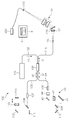
- the fundus oculi observation device 1 includes a fundus camera unit 2, an OCT unit 100, and an arithmetic control unit 200.
- the retinal camera unit 2 has almost the same optical system as a conventional retinal camera.
- the OCT unit 100 is provided with an optical system for acquiring an OCT image of the fundus.
- the arithmetic control unit 200 includes a computer that executes various arithmetic processes and control processes.
- the fundus camera unit 2 shown in FIG. 1 is provided with an optical system for acquiring a two-dimensional image (fundus photographed image) representing the surface form of the fundus oculi Ef of the eye E to be examined.
- the fundus photographed image includes an observation image and a photographed image.
- the observation image is, for example, a monochrome moving image formed at a predetermined frame rate using near infrared light.
- the captured image is a color image obtained by flashing visible light, for example.
- the fundus camera unit 2 may be configured to be able to acquire images other than these, such as a fluorescein fluorescent image, an indocyanine green fluorescent image, a spontaneous fluorescent image, and the like.
- the retinal camera unit 2 is provided with a chin rest and a forehead pad for supporting the subject's face so as not to move. Further, the fundus camera unit 2 is provided with an illumination optical system 10 and a photographing optical system 30.
- the illumination optical system 10 irradiates the fundus oculi Ef with illumination light.
- the photographing optical system 30 guides the fundus reflection light of the illumination light to the imaging device (CCD image sensors 35 and 38).
- the imaging optical system 30 guides the signal light from the OCT unit 100 to the fundus oculi Ef and guides the signal light passing through the fundus oculi Ef to the OCT unit 100.
- the observation light source 11 of the illumination optical system 10 is composed of, for example, a halogen lamp.
- the light (observation illumination light) output from the observation light source 11 is reflected by the reflection mirror 12 having a curved reflection surface, passes through the condensing lens 13, passes through the visible cut filter 14, and is converted into near infrared light. Become. Further, the observation illumination light is once converged in the vicinity of the photographing light source 15, reflected by the mirror 16, and passes through the relay lenses 17 and 18, the diaphragm 19 and the relay lens 20. Then, the observation illumination light is reflected by the peripheral part (region around the hole part) of the perforated mirror 21 and illuminates the fundus oculi Ef via the objective lens 22.
- the fundus reflection light of the observation illumination light is refracted by the objective lens 22, passes through a hole formed in the central region of the aperture mirror 21, passes through the dichroic mirror 55, passes through the focusing lens 31, and then goes through the dichroic mirror. 32 is reflected. Further, the fundus reflection light passes through the half mirror 40, is reflected by the dichroic mirror 33, and forms an image on the light receiving surface of the CCD image sensor 35 by the condenser lens 34.
- the CCD image sensor 35 detects fundus reflected light at a predetermined frame rate, for example.
- the display device 3 displays an image (observation image) K based on fundus reflected light detected by the CCD image sensor 35.
- the photographing light source 15 is constituted by, for example, a xenon lamp.
- the light (imaging illumination light) output from the imaging light source 15 is applied to the fundus oculi Ef through the same path as the observation illumination light.
- the fundus reflection light of the imaging illumination light is guided to the dichroic mirror 33 through the same path as that of the observation illumination light, passes through the dichroic mirror 33, is reflected by the mirror 36, and is reflected by the condenser lens 37 of the CCD image sensor 38.
- An image is formed on the light receiving surface.
- On the display device 3, an image (captured image) H based on fundus reflection light detected by the CCD image sensor 38 is displayed.
- the display device 3 that displays the observation image K and the display device 3 that displays the captured image H may be the same or different.
- the LCD 39 displays a fixation target and a visual target for visual acuity measurement.
- the fixation target is a target for fixing the eye E to be examined, and is used at the time of fundus photographing or OCT measurement.
- a part of the light output from the LCD 39 is reflected by the half mirror 40, reflected by the dichroic mirror 32, passes through the focusing lens 31 and the dichroic mirror 55, and passes through the hole of the perforated mirror 21.
- the light is refracted by the objective lens 22 and projected onto the fundus oculi Ef.
- the fixation position of the eye E can be changed by changing the display position of the fixation target on the screen of the LCD 39.
- As the fixation position of the eye E for example, a position for acquiring an image centered on the macular portion of the fundus oculi Ef, or a position for acquiring an image centered on the optic disc as in the case of a conventional fundus camera And a position for acquiring an image centered on the fundus center between the macula and the optic disc.
- the fundus camera unit 2 is provided with an alignment optical system 50 and a focus optical system 60 as in the conventional fundus camera.
- the alignment optical system 50 generates a visual target (alignment visual target) for performing alignment (alignment) of the apparatus optical system with respect to the eye E.
- the focus optical system 60 generates a visual target (split visual target) for focusing on the fundus oculi Ef.
- the light (alignment light) output from the LED (Light Emitting Diode) 51 of the alignment optical system 50 is reflected by the dichroic mirror 55 via the apertures 52 and 53 and the relay lens 54, and passes through the hole portion of the perforated mirror 21. It passes through and is projected onto the cornea of the eye E by the objective lens 22.
- the corneal reflection light of the alignment light passes through the objective lens 22 and the hole, and a part thereof passes through the dichroic mirror 55, passes through the focusing lens 31, is reflected by the dichroic mirror 32, and passes through the half mirror 40. Then, it is reflected by the dichroic mirror 33 and projected onto the light receiving surface of the CCD image sensor 35 by the condenser lens 34.
- a light reception image (alignment target) by the CCD image sensor 35 is displayed on the display device 3 together with the observation image K.
- the user performs alignment by performing the same operation as that of a conventional fundus camera. Further, the arithmetic control unit 200 may perform alignment by analyzing the position of the alignment target and moving the optical system.
- the reflecting surface of the reflecting rod 67 is obliquely provided on the optical path of the illumination optical system 10.
- the light (focus light) output from the LED 61 of the focus optical system 60 passes through the relay lens 62, is separated into two light beams by the split target plate 63, passes through the two-hole aperture 64, and is reflected by the mirror 65.
- the light is once focused on the reflecting surface of the reflecting bar 67 by the condenser lens 66 and reflected. Further, the focus light passes through the relay lens 20, is reflected by the perforated mirror 21, and forms an image on the fundus oculi Ef by the objective lens 22.
- the fundus reflection light of the focus light is detected by the CCD image sensor 35 through the same path as the corneal reflection light of the alignment light.
- a light reception image (split target) by the CCD image sensor 35 is displayed on the display device 3 together with the observation image.
- the arithmetic and control unit 200 analyzes the position of the split target and moves the focusing lens 31 and the focus optical system 60 to focus, as in the conventional case. Alternatively, focusing may be performed manually while visually checking the split target.
- An optical path including a mirror 41, a collimator lens 42, and galvanometer mirrors 43 and 44 is provided behind the dichroic mirror 32. This optical path is guided to the OCT unit 100.
- the galvanometer mirror 44 scans the signal light LS from the OCT unit 100 in the x direction.
- the galvanometer mirror 43 scans the signal light LS in the y direction.
- the OCT unit 100 is provided with an optical system for acquiring an OCT image of the fundus oculi Ef (see FIG. 2).
- This optical system has the same configuration as a conventional Fourier domain type OCT apparatus. That is, this optical system divides low-coherence light into reference light and signal light, and generates interference light by causing interference between the signal light passing through the fundus oculi Ef and the reference light passing through the reference optical path. It is configured to detect spectral components. This detection result (detection signal) is sent to the arithmetic control unit 200.
- the light source unit 101 outputs a broadband low-coherence light L0.
- the low coherence light L0 includes, for example, a near-infrared wavelength band (about 800 nm to 900 nm) and has a temporal coherence length of about several tens of micrometers. Note that near-infrared light having a wavelength band invisible to the human eye, for example, a center wavelength of about 1050 to 1060 nm, may be used as the low-coherence light L0.
- the light source unit 101 includes a super luminescent diode (Super Luminescent Diode: SLD), an LED, and an optical output device such as an SOA (Semiconductor Optical Amplifier).
- SLD Super Luminescent Diode
- LED an LED
- SOA semiconductor Optical Amplifier
- the low coherence light L0 output from the light source unit 101 is guided to the fiber coupler 103 by the optical fiber 102, and is divided into the signal light LS and the reference light LR.
- the fiber coupler 103 functions as both a means for splitting light (splitter) and a means for combining light (coupler), but here it is conventionally referred to as a “fiber coupler”.
- the signal light LS is guided by the optical fiber 104 and becomes a parallel light beam by the collimator lens unit 105. Further, the signal light LS is reflected by the respective galvanometer mirrors 44 and 43, collected by the collimator lens 42, reflected by the mirror 41, transmitted through the dichroic mirror 32, and through the same path as the light from the LCD 39, the fundus oculi Ef. Is irradiated. The signal light LS is scattered and reflected on the fundus oculi Ef. The scattered light and reflected light may be collectively referred to as fundus reflected light of the signal light LS. The fundus reflection light of the signal light LS travels in the opposite direction on the same path and is guided to the fiber coupler 103.
- the reference light LR is guided by the optical fiber 106 and becomes a parallel light beam by the collimator lens unit 107. Further, the reference light LR is reflected by the mirrors 108, 109, 110, is attenuated by the ND (Neutral Density) filter 111, is reflected by the mirror 112, and forms an image on the reflection surface of the reference mirror 114 by the collimator lens 113. . The reference light LR reflected by the reference mirror 114 travels in the opposite direction on the same path and is guided to the fiber coupler 103.
- An optical element for dispersion compensation such as a pair prism
- an optical element for polarization correction such as a wavelength plate
- the fiber coupler 103 combines the fundus reflection light of the signal light LS and the reference light LR reflected by the reference mirror 114.
- the interference light LC thus generated is guided by the optical fiber 115 and emitted from the emission end 116. Further, the interference light LC is converted into a parallel light beam by the collimator lens 117, dispersed (spectral decomposition) by the diffraction grating 118, condensed by the condenser lens 119, and projected onto the light receiving surface of the CCD image sensor 120.
- the diffraction grating 118 shown in FIG. 2 is a transmission type, but a reflection type diffraction grating may be used.
- the CCD image sensor 120 is, for example, a line sensor, and detects each spectral component of the split interference light LC and converts it into electric charges.
- the CCD image sensor 120 accumulates this electric charge and generates a detection signal. Further, the CCD image sensor 120 sends this detection signal to the arithmetic control unit 200.
- a Michelson type interferometer is used, but any type of interferometer such as a Mach-Zehnder type can be appropriately used.
- any type of interferometer such as a Mach-Zehnder type can be appropriately used.
- another form of image sensor for example, a CMOS (Complementary Metal Oxide Semiconductor) image sensor or the like can be used.
- CMOS Complementary Metal Oxide Semiconductor
- the configuration of the arithmetic control unit 200 will be described.
- the arithmetic control unit 200 analyzes the detection signal input from the CCD image sensor 120 and forms an OCT image of the fundus oculi Ef.
- the arithmetic processing for this is the same as that of a conventional Fourier domain type OCT apparatus.
- the arithmetic control unit 200 controls each part of the fundus camera unit 2, the display device 3, and the OCT unit 100.
- the arithmetic and control unit 200 displays an OCT image such as a tomographic image G (see FIG. 2) of the fundus oculi Ef on the display device 3.
- the arithmetic control unit 200 controls the operation of the observation light source 11, the imaging light source 15 and the LEDs 51 and 61, the operation control of the LCD 39, the movement control of the focusing lens 31, and the movement control of the reflector 67. Further, movement control of the focus optical system 60, operation control of the galvanometer mirrors 43 and 44, and the like are performed.
- the arithmetic control unit 200 performs operation control of the light source unit 101, movement control of the reference mirror 114 and collimator lens 113, operation control of the CCD image sensor 120, and the like.
- the arithmetic control unit 200 includes, for example, a microprocessor, a RAM, a ROM, a hard disk drive, a communication interface, and the like, as in a conventional computer.
- a computer program for controlling the fundus oculi observation device 1 is stored in a storage device such as a hard disk drive.
- the arithmetic control unit 200 may include a dedicated circuit board that forms an OCT image based on a detection signal from the CCD image sensor 120.
- the arithmetic control unit 200 may include an operation device (input device) such as a keyboard and a mouse, and a display device such as an LCD.
- the fundus camera unit 2, the display device 3, the OCT unit 100, and the arithmetic control unit 200 may be configured integrally (that is, in a single casing) or may be configured separately.
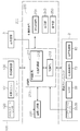
- Control system The configuration of the control system of the fundus oculi observation device 1 will be described with reference to FIG.
- the control system of the fundus oculi observation device 1 is configured around the control unit 210 of the arithmetic control unit 200.
- the control unit 210 includes, for example, the aforementioned microprocessor, RAM, ROM, hard disk drive, communication interface, and the like.
- the control unit 210 is provided with a main control unit 211 and a storage unit 213.
- the main control unit 211 performs the various controls described above.
- the main control unit 211 controls the scanning drive unit 70 and the focusing drive unit 80 of the fundus camera unit 2 and the light source unit 101 and the reference drive unit 130 of the OCT unit 100. Further, the main control unit 211 performs processing for writing data into the storage unit 213 and processing for reading data from the storage unit 213.
- the scanning drive unit 70 includes a servo motor, for example, and independently changes the directions of the galvanometer mirrors 43 and 44.
- the focusing drive unit 80 includes, for example, a pulse motor, and moves the focusing lens 31 in the optical axis direction. Thereby, the focus position of the light toward the fundus oculi Ef is changed.
- the reference driving unit 130 includes, for example, a pulse motor, and moves the collimator lens 113 and the reference mirror 114 integrally along the traveling direction of the reference light LR.
- the scanning control unit 70 functions as the “scanning unit” of the present invention together with the galvanometer mirrors 43 and 44.
- the control of the scanning drive unit 70 is executed by the scanning control unit 212.
- the scanning control unit 212 sequentially scans the signal light LS along a plurality of adjacent scanning lines.
- the scanning control unit 212 is an example of the “control unit” in the present invention.
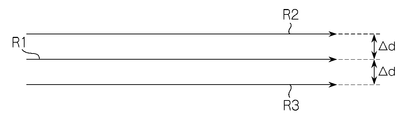
- FIG. 1 A specific example of the scanning mode realized by the scanning control unit 212 is shown in FIG.
- the signal light LS is scanned along the three scanning lines R1, R2, and R3.
- An interval ⁇ d between adjacent scanning lines is appropriately set in advance. It is assumed that 50 scans are performed to form one tomographic image (averaged tomographic image). At that time, scanning is performed in the following order: R1 ⁇ R2 ⁇ R3 ⁇ R1 ⁇ R2 ⁇ R3 ⁇ R1... ⁇ R1 ⁇ R2.
- this scanning mode three scanning lines R1, R2, and R3 are repeatedly scanned in this order to perform 50 scans. Note that the number of times of repeated scanning is not limited to 50, and an arbitrary number of times can be set.
- the interval between the scanning lines R1 and R2 may not be equal to the interval between the scanning lines R1 and R3. It is also possible to change the scanning line interval manually or automatically. In the case of manual operation, the examiner performs this using the display unit 240 and the operation unit 250. As an automatic case, for example, a value at the time of a past examination can be read and set, or a value set in advance according to a wound name or an observation target part can be read and set.
- the storage unit 213 stores various data.
- the data stored in the storage unit 213 includes, for example, image data of an OCT image, image data of a fundus photographic image, and eye information to be examined.
- the eye information includes information about the subject such as patient ID and name, and information about the eye such as left / right eye identification information.
- the image forming unit 220 forms tomographic image data of the fundus oculi Ef based on the detection signal from the CCD image sensor 120.
- This process includes processes such as noise removal (noise reduction), filter processing, and FFT (Fast Fourier Transform) as in the conventional Fourier domain type optical coherence tomography.
- the image forming unit 220 forms a tomographic image along each scanning line.
- the image forming unit 220 sequentially forms a plurality of tomographic images based on the detection result of the interference light LC based on the signal light LS sequentially scanned along the plurality of scanning lines by the scanning control unit 212.
- the image forming unit 220 sequentially forms 50 tomographic images corresponding to 50 scans.
- the image forming unit 220 includes, for example, the above-described circuit board and communication interface.
- image data and “image” presented based on the “image data” may be identified with each other.
- the image forming unit 220 is an example of the “image forming unit” in the present invention.
- the image processing unit 230 performs various types of image processing and analysis processing on the image formed by the image forming unit 220. For example, the image processing unit 230 executes various correction processes such as image brightness correction and dispersion correction.
- the image processing unit 230 executes known image processing such as interpolation processing for interpolating pixels between tomographic images to form image data of a three-dimensional image of the fundus oculi Ef.
- the image data of a three-dimensional image means image data in which pixel positions are defined by a three-dimensional coordinate system.
- image data of a three-dimensional image there is image data composed of voxels arranged three-dimensionally. This image data is called volume data or voxel data.
- the image processing unit 230 When displaying an image based on volume data, the image processing unit 230 performs a rendering process (such as volume rendering or MIP (Maximum Intensity Projection)) on the volume data, and views the image from a specific line-of-sight direction.
- Image data of a pseudo three-dimensional image is formed. This pseudo three-dimensional image is displayed on a display device such as the display unit 240.
- stack data of a plurality of tomographic images is image data of a three-dimensional image.
- the stack data is image data obtained by three-dimensionally arranging a plurality of tomographic images obtained along a plurality of scanning lines based on the positional relationship of the scanning lines. That is, stack data is image data obtained by expressing a plurality of tomographic images originally defined by individual two-dimensional coordinate systems by one three-dimensional coordinate system (that is, by embedding them in one three-dimensional space). is there.
- the image processing unit 230 is provided with an average processing unit 231.
- the average processing unit 231 forms an averaged tomographic image by aligning a plurality of tomographic images corresponding to the plurality of scanning lines formed by the image forming unit 220 and averaging the pixel values.
- the average processing unit 231 is an example of the “image processing unit” of the present invention. A specific example of processing executed by the average processing unit 231 will be described.
- the average processing unit 231 calculates an image correlation with each of the other tomographic images for each of the 50 tomographic images. As this calculation process, a known image correlation calculation process can be applied.
- the average processing unit 231 specifies a tomographic image having a minimum image correlation with other tomographic images among these 50 tomographic images.
- the value of image correlation with other tomographic images (49) is added, and the tomographic image having the minimum sum is specified.
- the tomographic image specified in this way is a tomographic image with the smallest image “deviation” with respect to other tomographic images.
- This tomographic image is a tomographic image (reference tomographic image) used as a reference in the averaging process for removing speckle noise.
- the average processing unit 231 selects a tomographic image whose image correlation with the reference tomographic image is equal to or greater than a predetermined threshold among 49 tomographic images excluding the reference tomographic image.
- the selected tomographic image has a high image correlation with the reference tomographic image. In other words, this process eliminates a tomographic image having a large “deviation” of the image with respect to the reference tomographic image.
- the threshold is set in advance. In general, when the threshold value is increased (decreased), the number of tomographic images selected is decreased (increased).
- the threshold value can be selected in consideration of the number of tomographic images to be selected.
- the averaging processing unit 231 forms a single tomographic image (averaged tomographic image) by aligning the selected tomographic images and averaging the pixel values.
- the alignment result executed when the image correlation calculation is performed can be applied. It is also possible to specify a characteristic part (for example, fundus surface, unevenness, blood vessel, etc.) in each tomographic image and match these positions.
- the average processing unit 231 adds pixel values at each pixel position to the tomographic images that have been aligned, and divides the sum value by the number of selected tomographic images. The value of this quotient becomes the average pixel value at the pixel position. This process is performed at each pixel position, and an average tomographic image is obtained by arranging pixels having an average pixel value according to the pixel position.
- the image processing unit 230 that functions as described above includes, for example, the aforementioned microprocessor, RAM, ROM, hard disk drive, circuit board, and the like.
- a storage device such as a hard disk drive, a computer program for causing the microprocessor to execute the above functions is stored in advance.
- the display unit 240 includes the display device of the arithmetic control unit 200 described above.
- the operation unit 250 includes the operation device of the arithmetic control unit 200 described above.
- the operation unit 250 may include various buttons and keys provided on the housing of the fundus oculi observation device 1 or outside.
- the operation unit 250 may include a joystick, an operation panel, or the like provided on the housing.
- the display unit 240 may include various display devices such as a touch panel monitor provided on the housing of the fundus camera unit 2.
- the display unit 240 and the operation unit 250 need not be configured as individual devices.
- a device in which a display function and an operation function are integrated, such as a touch panel monitor, can be used.
- Examples of the scanning mode of the signal light LS by the fundus oculi observation device 1 include a horizontal scan, a vertical scan, a cross scan, a radiation scan, a circle scan, a concentric scan, and a spiral (vortex) scan. These scanning modes are selectively used as appropriate in consideration of the observation site of the fundus, the analysis target (such as retinal thickness), the time required for scanning, the precision of scanning, and the like.
- the horizontal scan is to scan the signal light LS in the horizontal direction (x direction).
- the horizontal scan also includes an aspect in which the signal light LS is scanned along a plurality of horizontal scanning lines arranged in the vertical direction (y direction). In this aspect, it is possible to arbitrarily set the scanning line interval. Further, the above-described three-dimensional image can be formed by sufficiently narrowing the interval between adjacent scanning lines (three-dimensional scanning). The same applies to the vertical scan.
- the cross scan scans the signal light LS along a cross-shaped trajectory composed of two linear trajectories (straight trajectories) orthogonal to each other.
- the signal light LS is scanned along a radial trajectory composed of a plurality of linear trajectories arranged at a predetermined angle.
- the cross scan is an example of a radiation scan.
- the circle scan scans the signal light LS along a circular locus.
- the signal light LS is scanned along a plurality of circular trajectories arranged concentrically around a predetermined center position.
- a circle scan is an example of a concentric scan.
- the signal light LS is scanned along a spiral (spiral) locus while the radius of rotation is gradually reduced (or increased).
- the galvanometer mirrors 43 and 44 are configured to scan the signal light LS in directions orthogonal to each other, the signal light LS can be scanned independently in the x direction and the y direction, respectively. Furthermore, by simultaneously controlling the directions of the galvanometer mirrors 43 and 44, it is possible to scan the signal light LS along an arbitrary locus on the xy plane. Thereby, various scanning modes as described above can be realized.
- a tomographic image in the fundus depth direction (z direction) along the scanning line (scanning locus) can be formed.
- the above-described three-dimensional image can be formed.
- the region on the fundus oculi Ef to be scanned with the signal light LS as described above, that is, the region on the fundus oculi Ef to be subjected to OCT measurement is referred to as a scanning region.
- the scanning area in the three-dimensional scan is a rectangular area in which a plurality of horizontal scans are arranged.
- the scanning area in the concentric scan is a disk-shaped area surrounded by the locus of the circular scan with the maximum diameter.
- the scanning area in the radial scan is a disk-shaped (or polygonal) area connecting both end positions of each scan line.
- the fundus oculi observation device 1 it is possible to align tomographic image groups along a plurality of adjacent scanning lines and average pixel values at each pixel position to form an averaged tomographic image. By averaging the tomographic image groups with slightly different scanning positions in this way, speckle noise is removed more effectively than when acquiring the tomographic image groups obtained by scanning the same position as in the prior art. be able to.
- the same tomographic image can be obtained by scanning the same position as in the prior art.
- These tomographic images contain almost the same speckle noise. Therefore, even if these are averaged, the speckle noise included in each tomographic image is not effectively averaged, and as a result, it cannot be removed.
- tomographic images with slightly different scanning positions are averaged. Therefore, these tomographic images depict substantially the same part of the fundus oculi Ef, and the speckle noise mixed in these tomographic images is not the same. Therefore, speckle noise is averaged more effectively than the conventional method.
- a plurality of (for example, 50) tomographic images are formed by repeatedly scanning the signal light LS a predetermined number of times along a plurality of scanning lines (R1 to R3).
- An averaged tomographic image can be formed based on the tomographic image.
- the actual scanning position on the fundus oculi Ef is slightly different even when scanning along the same scanning line (for example, R1).
- the interval between adjacent scanning lines can be set as appropriate in consideration of the size of the fundus tissue to be drawn, the fixation eye movement of the eye to be examined, and the like.
- the interval between adjacent scanning lines depends on the size of the tissue to be measured and the motion state of the object to be measured. Can be set appropriately.
- the averaged tomographic image is obtained by averaging a plurality of tomographic images, but not all of the plurality of tomographic images are obtained by measuring the same position. Therefore, in the above case, the position of the averaged tomographic image must be determined.
- registration is performed by aligning an image obtained by integrating a plurality of averaged tomographic images in the z direction (integrated image) and a fundus image, thereby obtaining each averaged tomogram and fundus image. Is a process of associating positions in the xy direction.
- a tomographic image having a maximum image correlation with another tomographic image among a plurality of tomographic images can be selected, and the position of this tomographic image can be set as the position of the averaged tomographic image.
- one of a plurality of scanning lines is designated in advance, and the position of the designated scanning line (or one of the tomographic images along the scanning line) is averaged. The position of the tomographic image can be set.
- the depth of an image region corresponding to the part (in the z direction) among a plurality of tomographic images is selected, and the position of this tomographic image can be set as the position of the averaged tomographic image.
- an image region corresponding to a predetermined feature point on the fundus surface is specified in both a tomographic image and a fundus photographic image, and includes the image region that matches the position of the image region in the fundus photographic image.
- a tomographic image is selected, and the position of this tomographic image can be set as the position of the averaged tomographic image. Note that the processing for determining the position of the averaged tomographic image is not limited to these examples.
- the position of the reference mirror 114 is changed to change the optical path length difference between the optical path of the signal light LS and the optical path of the reference light LR, but the method of changing the optical path length difference is limited to this. Is not to be done.
- the optical path length difference can be changed by moving the fundus camera unit 2 or the OCT unit 100 with respect to the eye E to change the optical path length of the signal light LS. It is also effective to change the optical path length difference by moving the measurement object in the depth direction (z direction), particularly when the measurement object is not a living body part.
- the computer program in the above embodiment can be stored in any recording medium readable by a computer.
- this recording medium for example, an optical disk, a magneto-optical disk (CD-ROM / DVD-RAM / DVD-ROM / MO, etc.), a magnetic storage medium (hard disk / floppy (registered trademark) disk / ZIP, etc.), etc. are used. Is possible. It can also be stored in a storage device such as a hard disk drive or memory.
Landscapes
- Health & Medical Sciences (AREA)
- Life Sciences & Earth Sciences (AREA)
- Biomedical Technology (AREA)
- Molecular Biology (AREA)
- Radiology & Medical Imaging (AREA)
- Biophysics (AREA)
- Ophthalmology & Optometry (AREA)
- Engineering & Computer Science (AREA)
- Nuclear Medicine, Radiotherapy & Molecular Imaging (AREA)
- Heart & Thoracic Surgery (AREA)
- Medical Informatics (AREA)
- Physics & Mathematics (AREA)
- Surgery (AREA)
- Animal Behavior & Ethology (AREA)
- General Health & Medical Sciences (AREA)
- Public Health (AREA)
- Veterinary Medicine (AREA)
- Eye Examination Apparatus (AREA)
- Investigating Or Analysing Materials By Optical Means (AREA)
Applications Claiming Priority (2)
| Application Number | Priority Date | Filing Date | Title |
|---|---|---|---|
| JP2009-246966 | 2009-10-27 | ||
| JP2009246966A JP5543171B2 (ja) | 2009-10-27 | 2009-10-27 | 光画像計測装置 |
Publications (1)
| Publication Number | Publication Date |
|---|---|
| WO2011052131A1 true WO2011052131A1 (ja) | 2011-05-05 |
Family
ID=43921569
Family Applications (1)
| Application Number | Title | Priority Date | Filing Date |
|---|---|---|---|
| PCT/JP2010/005634 Ceased WO2011052131A1 (ja) | 2009-10-27 | 2010-09-15 | 光画像計測装置 |
Country Status (2)
| Country | Link |
|---|---|
| JP (1) | JP5543171B2 (enExample) |
| WO (1) | WO2011052131A1 (enExample) |
Cited By (2)
| Publication number | Priority date | Publication date | Assignee | Title |
|---|---|---|---|---|
| WO2015003103A1 (en) * | 2013-07-02 | 2015-01-08 | Pine Development Corporation | Systems and methods for eliciting cutaneous sensations using electromagnetic radiation |
| US9449477B2 (en) | 2014-04-02 | 2016-09-20 | Pine Development Corporation | Applications of systems and methods for eliciting cutaneous sensations by electromagnetic radiation |
Families Citing this family (11)
| Publication number | Priority date | Publication date | Assignee | Title |
|---|---|---|---|---|
| JP5025715B2 (ja) * | 2009-12-08 | 2012-09-12 | キヤノン株式会社 | 断層画像撮影装置、画像処理装置、画像処理システム、画像処理装置の制御方法及びプログラム |
| JP5486543B2 (ja) | 2011-03-31 | 2014-05-07 | キヤノン株式会社 | 眼科撮像装置、眼科撮像装置の制御方法、およびプログラム |
| JP5631361B2 (ja) * | 2012-06-18 | 2014-11-26 | キヤノン株式会社 | 画像処理装置、画像処理方法及びプログラム |
| JP6075755B2 (ja) | 2012-11-19 | 2017-02-08 | 株式会社トプコン | 光画像計測装置 |
| JP5522305B1 (ja) * | 2013-09-24 | 2014-06-18 | 住友電気工業株式会社 | 光学的測定システムおよびその作動方法 |
| JP5634587B2 (ja) * | 2013-10-30 | 2014-12-03 | キヤノン株式会社 | 画像処理装置、画像処理方法、及びプログラム |
| WO2016080914A1 (en) * | 2014-11-20 | 2016-05-26 | Agency For Science, Technology And Research | Speckle reduction in optical coherence tomography images |
| JP2016112267A (ja) | 2014-12-16 | 2016-06-23 | キヤノン株式会社 | 眼科装置、画像生成方法およびプログラム |
| JP6776317B2 (ja) * | 2018-12-21 | 2020-10-28 | キヤノン株式会社 | 画像処理装置、画像処理方法およびプログラム |
| JP7077283B2 (ja) * | 2019-09-03 | 2022-05-30 | キヤノン株式会社 | 眼科装置、画像生成方法およびプログラム |
| CN114092371B (zh) * | 2021-11-29 | 2025-06-27 | 唯智医疗科技(佛山)有限公司 | 自适应重复扫描方法及装置 |
Citations (4)
| Publication number | Priority date | Publication date | Assignee | Title |
|---|---|---|---|---|
| JP2008145376A (ja) * | 2006-12-13 | 2008-06-26 | Fujifilm Corp | 光断層画像化システム |
| JP2008237238A (ja) * | 2007-03-23 | 2008-10-09 | Topcon Corp | 光画像計測装置、画像処理装置及びプログラム |
| JP2008289579A (ja) * | 2007-05-23 | 2008-12-04 | Topcon Corp | 眼底観察装置及びそれを制御するプログラム |
| JP2009066015A (ja) * | 2007-09-10 | 2009-04-02 | Univ Of Tokyo | 眼底観察装置、眼科画像処理装置及びプログラム |
-
2009
- 2009-10-27 JP JP2009246966A patent/JP5543171B2/ja active Active
-
2010
- 2010-09-15 WO PCT/JP2010/005634 patent/WO2011052131A1/ja not_active Ceased
Patent Citations (4)
| Publication number | Priority date | Publication date | Assignee | Title |
|---|---|---|---|---|
| JP2008145376A (ja) * | 2006-12-13 | 2008-06-26 | Fujifilm Corp | 光断層画像化システム |
| JP2008237238A (ja) * | 2007-03-23 | 2008-10-09 | Topcon Corp | 光画像計測装置、画像処理装置及びプログラム |
| JP2008289579A (ja) * | 2007-05-23 | 2008-12-04 | Topcon Corp | 眼底観察装置及びそれを制御するプログラム |
| JP2009066015A (ja) * | 2007-09-10 | 2009-04-02 | Univ Of Tokyo | 眼底観察装置、眼科画像処理装置及びプログラム |
Cited By (4)
| Publication number | Priority date | Publication date | Assignee | Title |
|---|---|---|---|---|
| WO2015003103A1 (en) * | 2013-07-02 | 2015-01-08 | Pine Development Corporation | Systems and methods for eliciting cutaneous sensations using electromagnetic radiation |
| US10295823B2 (en) | 2013-07-02 | 2019-05-21 | Pine Development Corporation | Systems and methods for eliciting cutaneous sensations using electromagnetic radiation |
| US9449477B2 (en) | 2014-04-02 | 2016-09-20 | Pine Development Corporation | Applications of systems and methods for eliciting cutaneous sensations by electromagnetic radiation |
| US10037661B2 (en) | 2014-04-02 | 2018-07-31 | Pine Development Corporation | Applications of systems and methods for eliciting cutaneous sensations by electromagnetic radiation |
Also Published As
| Publication number | Publication date |
|---|---|
| JP2011095005A (ja) | 2011-05-12 |
| JP5543171B2 (ja) | 2014-07-09 |
Similar Documents
| Publication | Publication Date | Title |
|---|---|---|
| JP5543171B2 (ja) | 光画像計測装置 | |
| JP5437755B2 (ja) | 眼底観察装置 | |
| JP5867719B2 (ja) | 光画像計測装置 | |
| JP5912358B2 (ja) | 眼底観察装置 | |
| JP5628636B2 (ja) | 眼底画像処理装置及び眼底観察装置 | |
| JP5415902B2 (ja) | 眼科観察装置 | |
| JP6045895B2 (ja) | 眼科観察装置 | |
| JP5936254B2 (ja) | 眼底観察装置及び眼底画像解析装置 | |
| WO2010125746A1 (ja) | 眼底観察装置 | |
| JP5941761B2 (ja) | 眼科撮影装置及び眼科画像処理装置 | |
| JP5513101B2 (ja) | 光画像計測装置 | |
| JP5706506B2 (ja) | 眼科装置 | |
| JP5378157B2 (ja) | 眼科観察装置 | |
| JP5514026B2 (ja) | 眼底画像処理装置及び眼底観察装置 | |
| JP6101475B2 (ja) | 眼科観察装置 | |
| WO2013085042A1 (ja) | 眼底観察装置 | |
| JP5919175B2 (ja) | 光画像計測装置 | |
| JP6021289B2 (ja) | 血流情報生成装置、血流情報生成方法、及びプログラム | |
| JP6099782B2 (ja) | 眼科撮影装置 | |
| JP6106300B2 (ja) | 眼科撮影装置 | |
| JP6106299B2 (ja) | 眼科撮影装置及び眼科画像処理装置 |
Legal Events
| Date | Code | Title | Description |
|---|---|---|---|
| 121 | Ep: the epo has been informed by wipo that ep was designated in this application |
Ref document number: 10826269 Country of ref document: EP Kind code of ref document: A1 |
|
| NENP | Non-entry into the national phase |
Ref country code: DE |
|
| 122 | Ep: pct application non-entry in european phase |
Ref document number: 10826269 Country of ref document: EP Kind code of ref document: A1 |