WO2011052131A1 - 光画像計測装置 - Google Patents
光画像計測装置 Download PDFInfo
- Publication number
- WO2011052131A1 WO2011052131A1 PCT/JP2010/005634 JP2010005634W WO2011052131A1 WO 2011052131 A1 WO2011052131 A1 WO 2011052131A1 JP 2010005634 W JP2010005634 W JP 2010005634W WO 2011052131 A1 WO2011052131 A1 WO 2011052131A1
- Authority
- WO
- WIPO (PCT)
- Prior art keywords
- image
- light
- tomographic
- scanning
- optical
- Prior art date
Links
Images

Classifications
-
- A—HUMAN NECESSITIES
- A61—MEDICAL OR VETERINARY SCIENCE; HYGIENE
- A61B—DIAGNOSIS; SURGERY; IDENTIFICATION
- A61B3/00—Apparatus for testing the eyes; Instruments for examining the eyes
- A61B3/10—Objective types, i.e. instruments for examining the eyes independent of the patients' perceptions or reactions
- A61B3/102—Objective types, i.e. instruments for examining the eyes independent of the patients' perceptions or reactions for optical coherence tomography [OCT]
Definitions
- the present invention relates to an optical image measurement device that forms an image of an object to be measured using optical coherence tomography (OCT).
- OCT optical coherence tomography
- OCT that forms an image representing the surface form and internal form of an object to be measured using a light beam from a laser light source or the like has attracted attention. Since OCT has no invasiveness to the human body like X-ray CT, it is expected to be applied particularly in the medical field and the biological field. For example, in the field of ophthalmology, an apparatus for forming an image of the fundus oculi, cornea, etc. has entered a practical stage.
- Patent Document 1 discloses an apparatus to which OCT is applied.
- the measuring arm scans an object with a rotary turning mirror (galvanomirror)
- a reference mirror is installed on the reference arm
- the intensity of the interference light of the light beam from the measuring arm and the reference arm is dispersed at the exit.
- An interferometer is provided for analysis by the instrument.
- the reference arm is configured to change the phase of the reference light beam stepwise by a discontinuous value.
- Patent Document 1 uses a so-called “Fourier Domain OCT (Fourier Domain OCT)” technique.
- Fourier Domain OCT Frier Domain OCT
- a low-coherence beam is irradiated onto the object to be measured, the reflected light and the reference light are superimposed to generate interference light, and the spectral intensity distribution of the interference light is acquired and subjected to Fourier transform.
- the form of the object to be measured in the depth direction (z direction) is imaged.
- this type of technique is also called a spectral domain.
- the apparatus described in Patent Document 1 includes a galvanometer mirror that scans a light beam (signal light), thereby forming an image of a desired measurement target region of the object to be measured. Since this apparatus is configured to scan the light beam only in one direction (x direction) orthogonal to the z direction, the image formed by this apparatus is in the scanning direction (x direction) of the light beam. It becomes a two-dimensional tomogram in the depth direction (z direction) along.
- a plurality of two-dimensional tomographic images in the horizontal direction are formed by scanning (scanning) the signal light in the horizontal direction (x direction) and the vertical direction (y direction), and based on the plurality of tomographic images.
- a technique for acquiring and imaging three-dimensional tomographic information of a measurement range is disclosed. Examples of the three-dimensional imaging include a method of displaying a plurality of tomographic images side by side in a vertical direction (referred to as stack data) and a method of rendering a plurality of tomographic images to form a three-dimensional image. Conceivable.
- Patent Documents 3 and 4 disclose other types of OCT apparatuses.
- Patent Document 3 scans the wavelength of light applied to an object to be measured, acquires a spectral intensity distribution based on interference light obtained by superimposing reflected light of each wavelength and reference light
- an OCT apparatus for imaging the form of an object to be measured by performing Fourier transform on the object is described.
- Such an OCT apparatus is called a swept source type.
- the swept source type is a kind of Fourier domain type.
- Patent Document 4 the traveling direction of light is obtained by irradiating the object to be measured with light having a predetermined beam diameter, and analyzing the component of interference light obtained by superimposing the reflected light and the reference light.
- An OCT apparatus for forming an image of an object to be measured in a cross-section orthogonal to is described. Such an OCT apparatus is called a full-field type or an en-face type.
- Patent Document 5 discloses a configuration in which OCT is applied to the ophthalmic field.
- a fundus camera Prior to the application of OCT, a fundus camera, a slit lamp, or the like was used as an apparatus for observing the eye to be examined (see, for example, Patent Document 6 and Patent Document 7).
- a fundus camera is a device that shoots the fundus by illuminating the subject's eye with illumination light and receiving the fundus reflection light.
- a slit lamp is a device that acquires an image of a cross-section of the cornea by cutting off a light section of the cornea using slit light.
- An apparatus using OCT has an advantage over a fundus camera or the like in that a high-definition image can be acquired, and further, a tomographic image or a three-dimensional image can be acquired.
- an apparatus using OCT can be applied to observation of various parts of an eye to be examined and can acquire high-definition images, it has been applied to diagnosis of various ophthalmic diseases.
- speckle noise tends to occur in the formed image. Therefore, in an optical image measuring device of the type that scans signal light in the Fourier domain, etc., speckle noise is reduced by scanning the substantially same position of the object to be measured a plurality of times to form a plurality of tomographic images and averaging them. Is planned.
- the present invention has been made to solve the above-described problems, and an object thereof is to provide an optical image measurement device capable of obtaining an image from which speckle noise has been effectively removed. .
- the invention according to claim 1 divides low-coherence light into signal light and reference light, and the signal light passing through the object to be measured and the reference light passing through the reference light path
- An optical image measurement apparatus having an optical system that generates and detects interference light by superimposing and an image forming unit that forms a tomographic image of the object to be measured based on the detection result of the interference light,
- a scanning unit that scans the irradiation position of the signal light on the object to be measured; a control unit that controls the scanning unit to sequentially scan the signal light along a plurality of adjacent scanning lines; and the image formation Image processing means for aligning a plurality of tomographic images corresponding to the plurality of scanning lines formed by the means and averaging pixel values at each pixel position to form an averaged tomographic image.
- the invention according to claim 2 is the optical image measurement device according to claim 1, wherein the control means repeatedly executes scanning of the signal light along the plurality of scanning lines a predetermined number of times. The scanning unit is controlled as described above, and the image processing unit forms the averaged tomographic image based on a plurality of tomographic images obtained by the repeated scanning.
- the invention according to claim 3 is the optical image measuring device according to claim 2, wherein the image processing means is an image of each other tomographic image with respect to a reference tomographic image among the plurality of tomographic images. A correlation is calculated, and the averaged tomographic image is formed based on the value of the image correlation.
- the invention according to claim 4 is the optical image measurement device according to claim 3, wherein the image processing means calculates an image correlation between each of the plurality of tomographic images and other tomographic images. Then, a tomographic image having a minimum image correlation with another tomographic image is identified and used as the reference tomographic image.
- the invention according to claim 5 is the optical image measurement device according to claim 3, wherein the image processing means is based on only a tomographic image whose image correlation with the reference tomographic image is a predetermined threshold value or more. An averaged tomographic image is formed.
- the invention described in claim 6 is the optical image measurement device according to claim 1, wherein the plurality of scanning lines are arranged at a preset interval.
- the invention according to claim 7 is the optical image measurement device according to claim 6, wherein the intervals of the plurality of scanning lines are changeable.
- tomographic image groups along a plurality of adjacent scanning lines can be aligned, and averaged tomographic images can be formed by averaging pixel values at each pixel position.
- the optical image measurement apparatus forms a tomographic image or a three-dimensional image of an object to be measured using OCT.
- images acquired by OCT may be collectively referred to as OCT images.
- a measurement operation for forming an OCT image may be referred to as OCT measurement.
- an OCT technique of scanning the irradiation position of the signal light with respect to the object to be measured is used.
- a configuration to which Fourier domain type OCT is applied will be described in detail.
- a fundus oculi observation device that can acquire both an OCT image and a fundus oculi image of the fundus as in the device disclosed in Patent Document 5 is taken up.
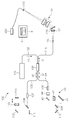
- the fundus oculi observation device 1 includes a fundus camera unit 2, an OCT unit 100, and an arithmetic control unit 200.
- the retinal camera unit 2 has almost the same optical system as a conventional retinal camera.
- the OCT unit 100 is provided with an optical system for acquiring an OCT image of the fundus.
- the arithmetic control unit 200 includes a computer that executes various arithmetic processes and control processes.
- the fundus camera unit 2 shown in FIG. 1 is provided with an optical system for acquiring a two-dimensional image (fundus photographed image) representing the surface form of the fundus oculi Ef of the eye E to be examined.
- the fundus photographed image includes an observation image and a photographed image.
- the observation image is, for example, a monochrome moving image formed at a predetermined frame rate using near infrared light.
- the captured image is a color image obtained by flashing visible light, for example.
- the fundus camera unit 2 may be configured to be able to acquire images other than these, such as a fluorescein fluorescent image, an indocyanine green fluorescent image, a spontaneous fluorescent image, and the like.
- the retinal camera unit 2 is provided with a chin rest and a forehead pad for supporting the subject's face so as not to move. Further, the fundus camera unit 2 is provided with an illumination optical system 10 and a photographing optical system 30.
- the illumination optical system 10 irradiates the fundus oculi Ef with illumination light.
- the photographing optical system 30 guides the fundus reflection light of the illumination light to the imaging device (CCD image sensors 35 and 38).
- the imaging optical system 30 guides the signal light from the OCT unit 100 to the fundus oculi Ef and guides the signal light passing through the fundus oculi Ef to the OCT unit 100.
- the observation light source 11 of the illumination optical system 10 is composed of, for example, a halogen lamp.
- the light (observation illumination light) output from the observation light source 11 is reflected by the reflection mirror 12 having a curved reflection surface, passes through the condensing lens 13, passes through the visible cut filter 14, and is converted into near infrared light. Become. Further, the observation illumination light is once converged in the vicinity of the photographing light source 15, reflected by the mirror 16, and passes through the relay lenses 17 and 18, the diaphragm 19 and the relay lens 20. Then, the observation illumination light is reflected by the peripheral part (region around the hole part) of the perforated mirror 21 and illuminates the fundus oculi Ef via the objective lens 22.
- the fundus reflection light of the observation illumination light is refracted by the objective lens 22, passes through a hole formed in the central region of the aperture mirror 21, passes through the dichroic mirror 55, passes through the focusing lens 31, and then goes through the dichroic mirror. 32 is reflected. Further, the fundus reflection light passes through the half mirror 40, is reflected by the dichroic mirror 33, and forms an image on the light receiving surface of the CCD image sensor 35 by the condenser lens 34.
- the CCD image sensor 35 detects fundus reflected light at a predetermined frame rate, for example.
- the display device 3 displays an image (observation image) K based on fundus reflected light detected by the CCD image sensor 35.
- the photographing light source 15 is constituted by, for example, a xenon lamp.
- the light (imaging illumination light) output from the imaging light source 15 is applied to the fundus oculi Ef through the same path as the observation illumination light.
- the fundus reflection light of the imaging illumination light is guided to the dichroic mirror 33 through the same path as that of the observation illumination light, passes through the dichroic mirror 33, is reflected by the mirror 36, and is reflected by the condenser lens 37 of the CCD image sensor 38.
- An image is formed on the light receiving surface.
- On the display device 3, an image (captured image) H based on fundus reflection light detected by the CCD image sensor 38 is displayed.
- the display device 3 that displays the observation image K and the display device 3 that displays the captured image H may be the same or different.
- the LCD 39 displays a fixation target and a visual target for visual acuity measurement.
- the fixation target is a target for fixing the eye E to be examined, and is used at the time of fundus photographing or OCT measurement.
- a part of the light output from the LCD 39 is reflected by the half mirror 40, reflected by the dichroic mirror 32, passes through the focusing lens 31 and the dichroic mirror 55, and passes through the hole of the perforated mirror 21.
- the light is refracted by the objective lens 22 and projected onto the fundus oculi Ef.
- the fixation position of the eye E can be changed by changing the display position of the fixation target on the screen of the LCD 39.
- As the fixation position of the eye E for example, a position for acquiring an image centered on the macular portion of the fundus oculi Ef, or a position for acquiring an image centered on the optic disc as in the case of a conventional fundus camera And a position for acquiring an image centered on the fundus center between the macula and the optic disc.
- the fundus camera unit 2 is provided with an alignment optical system 50 and a focus optical system 60 as in the conventional fundus camera.
- the alignment optical system 50 generates a visual target (alignment visual target) for performing alignment (alignment) of the apparatus optical system with respect to the eye E.
- the focus optical system 60 generates a visual target (split visual target) for focusing on the fundus oculi Ef.
- the light (alignment light) output from the LED (Light Emitting Diode) 51 of the alignment optical system 50 is reflected by the dichroic mirror 55 via the apertures 52 and 53 and the relay lens 54, and passes through the hole portion of the perforated mirror 21. It passes through and is projected onto the cornea of the eye E by the objective lens 22.
- the corneal reflection light of the alignment light passes through the objective lens 22 and the hole, and a part thereof passes through the dichroic mirror 55, passes through the focusing lens 31, is reflected by the dichroic mirror 32, and passes through the half mirror 40. Then, it is reflected by the dichroic mirror 33 and projected onto the light receiving surface of the CCD image sensor 35 by the condenser lens 34.
- a light reception image (alignment target) by the CCD image sensor 35 is displayed on the display device 3 together with the observation image K.
- the user performs alignment by performing the same operation as that of a conventional fundus camera. Further, the arithmetic control unit 200 may perform alignment by analyzing the position of the alignment target and moving the optical system.
- the reflecting surface of the reflecting rod 67 is obliquely provided on the optical path of the illumination optical system 10.
- the light (focus light) output from the LED 61 of the focus optical system 60 passes through the relay lens 62, is separated into two light beams by the split target plate 63, passes through the two-hole aperture 64, and is reflected by the mirror 65.
- the light is once focused on the reflecting surface of the reflecting bar 67 by the condenser lens 66 and reflected. Further, the focus light passes through the relay lens 20, is reflected by the perforated mirror 21, and forms an image on the fundus oculi Ef by the objective lens 22.
- the fundus reflection light of the focus light is detected by the CCD image sensor 35 through the same path as the corneal reflection light of the alignment light.
- a light reception image (split target) by the CCD image sensor 35 is displayed on the display device 3 together with the observation image.
- the arithmetic and control unit 200 analyzes the position of the split target and moves the focusing lens 31 and the focus optical system 60 to focus, as in the conventional case. Alternatively, focusing may be performed manually while visually checking the split target.
- An optical path including a mirror 41, a collimator lens 42, and galvanometer mirrors 43 and 44 is provided behind the dichroic mirror 32. This optical path is guided to the OCT unit 100.
- the galvanometer mirror 44 scans the signal light LS from the OCT unit 100 in the x direction.
- the galvanometer mirror 43 scans the signal light LS in the y direction.
- the OCT unit 100 is provided with an optical system for acquiring an OCT image of the fundus oculi Ef (see FIG. 2).
- This optical system has the same configuration as a conventional Fourier domain type OCT apparatus. That is, this optical system divides low-coherence light into reference light and signal light, and generates interference light by causing interference between the signal light passing through the fundus oculi Ef and the reference light passing through the reference optical path. It is configured to detect spectral components. This detection result (detection signal) is sent to the arithmetic control unit 200.
- the light source unit 101 outputs a broadband low-coherence light L0.
- the low coherence light L0 includes, for example, a near-infrared wavelength band (about 800 nm to 900 nm) and has a temporal coherence length of about several tens of micrometers. Note that near-infrared light having a wavelength band invisible to the human eye, for example, a center wavelength of about 1050 to 1060 nm, may be used as the low-coherence light L0.
- the light source unit 101 includes a super luminescent diode (Super Luminescent Diode: SLD), an LED, and an optical output device such as an SOA (Semiconductor Optical Amplifier).
- SLD Super Luminescent Diode
- LED an LED
- SOA semiconductor Optical Amplifier
- the low coherence light L0 output from the light source unit 101 is guided to the fiber coupler 103 by the optical fiber 102, and is divided into the signal light LS and the reference light LR.
- the fiber coupler 103 functions as both a means for splitting light (splitter) and a means for combining light (coupler), but here it is conventionally referred to as a “fiber coupler”.
- the signal light LS is guided by the optical fiber 104 and becomes a parallel light beam by the collimator lens unit 105. Further, the signal light LS is reflected by the respective galvanometer mirrors 44 and 43, collected by the collimator lens 42, reflected by the mirror 41, transmitted through the dichroic mirror 32, and through the same path as the light from the LCD 39, the fundus oculi Ef. Is irradiated. The signal light LS is scattered and reflected on the fundus oculi Ef. The scattered light and reflected light may be collectively referred to as fundus reflected light of the signal light LS. The fundus reflection light of the signal light LS travels in the opposite direction on the same path and is guided to the fiber coupler 103.
- the reference light LR is guided by the optical fiber 106 and becomes a parallel light beam by the collimator lens unit 107. Further, the reference light LR is reflected by the mirrors 108, 109, 110, is attenuated by the ND (Neutral Density) filter 111, is reflected by the mirror 112, and forms an image on the reflection surface of the reference mirror 114 by the collimator lens 113. . The reference light LR reflected by the reference mirror 114 travels in the opposite direction on the same path and is guided to the fiber coupler 103.
- An optical element for dispersion compensation such as a pair prism
- an optical element for polarization correction such as a wavelength plate
- the fiber coupler 103 combines the fundus reflection light of the signal light LS and the reference light LR reflected by the reference mirror 114.
- the interference light LC thus generated is guided by the optical fiber 115 and emitted from the emission end 116. Further, the interference light LC is converted into a parallel light beam by the collimator lens 117, dispersed (spectral decomposition) by the diffraction grating 118, condensed by the condenser lens 119, and projected onto the light receiving surface of the CCD image sensor 120.
- the diffraction grating 118 shown in FIG. 2 is a transmission type, but a reflection type diffraction grating may be used.
- the CCD image sensor 120 is, for example, a line sensor, and detects each spectral component of the split interference light LC and converts it into electric charges.
- the CCD image sensor 120 accumulates this electric charge and generates a detection signal. Further, the CCD image sensor 120 sends this detection signal to the arithmetic control unit 200.
- a Michelson type interferometer is used, but any type of interferometer such as a Mach-Zehnder type can be appropriately used.
- any type of interferometer such as a Mach-Zehnder type can be appropriately used.
- another form of image sensor for example, a CMOS (Complementary Metal Oxide Semiconductor) image sensor or the like can be used.
- CMOS Complementary Metal Oxide Semiconductor
- the configuration of the arithmetic control unit 200 will be described.
- the arithmetic control unit 200 analyzes the detection signal input from the CCD image sensor 120 and forms an OCT image of the fundus oculi Ef.
- the arithmetic processing for this is the same as that of a conventional Fourier domain type OCT apparatus.
- the arithmetic control unit 200 controls each part of the fundus camera unit 2, the display device 3, and the OCT unit 100.
- the arithmetic and control unit 200 displays an OCT image such as a tomographic image G (see FIG. 2) of the fundus oculi Ef on the display device 3.
- the arithmetic control unit 200 controls the operation of the observation light source 11, the imaging light source 15 and the LEDs 51 and 61, the operation control of the LCD 39, the movement control of the focusing lens 31, and the movement control of the reflector 67. Further, movement control of the focus optical system 60, operation control of the galvanometer mirrors 43 and 44, and the like are performed.
- the arithmetic control unit 200 performs operation control of the light source unit 101, movement control of the reference mirror 114 and collimator lens 113, operation control of the CCD image sensor 120, and the like.
- the arithmetic control unit 200 includes, for example, a microprocessor, a RAM, a ROM, a hard disk drive, a communication interface, and the like, as in a conventional computer.
- a computer program for controlling the fundus oculi observation device 1 is stored in a storage device such as a hard disk drive.
- the arithmetic control unit 200 may include a dedicated circuit board that forms an OCT image based on a detection signal from the CCD image sensor 120.
- the arithmetic control unit 200 may include an operation device (input device) such as a keyboard and a mouse, and a display device such as an LCD.
- the fundus camera unit 2, the display device 3, the OCT unit 100, and the arithmetic control unit 200 may be configured integrally (that is, in a single casing) or may be configured separately.
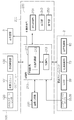
- Control system The configuration of the control system of the fundus oculi observation device 1 will be described with reference to FIG.
- the control system of the fundus oculi observation device 1 is configured around the control unit 210 of the arithmetic control unit 200.
- the control unit 210 includes, for example, the aforementioned microprocessor, RAM, ROM, hard disk drive, communication interface, and the like.
- the control unit 210 is provided with a main control unit 211 and a storage unit 213.
- the main control unit 211 performs the various controls described above.
- the main control unit 211 controls the scanning drive unit 70 and the focusing drive unit 80 of the fundus camera unit 2 and the light source unit 101 and the reference drive unit 130 of the OCT unit 100. Further, the main control unit 211 performs processing for writing data into the storage unit 213 and processing for reading data from the storage unit 213.
- the scanning drive unit 70 includes a servo motor, for example, and independently changes the directions of the galvanometer mirrors 43 and 44.
- the focusing drive unit 80 includes, for example, a pulse motor, and moves the focusing lens 31 in the optical axis direction. Thereby, the focus position of the light toward the fundus oculi Ef is changed.
- the reference driving unit 130 includes, for example, a pulse motor, and moves the collimator lens 113 and the reference mirror 114 integrally along the traveling direction of the reference light LR.
- the scanning control unit 70 functions as the “scanning unit” of the present invention together with the galvanometer mirrors 43 and 44.
- the control of the scanning drive unit 70 is executed by the scanning control unit 212.
- the scanning control unit 212 sequentially scans the signal light LS along a plurality of adjacent scanning lines.
- the scanning control unit 212 is an example of the “control unit” in the present invention.
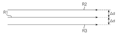
- FIG. 1 A specific example of the scanning mode realized by the scanning control unit 212 is shown in FIG.
- the signal light LS is scanned along the three scanning lines R1, R2, and R3.
- An interval ⁇ d between adjacent scanning lines is appropriately set in advance. It is assumed that 50 scans are performed to form one tomographic image (averaged tomographic image). At that time, scanning is performed in the following order: R1 ⁇ R2 ⁇ R3 ⁇ R1 ⁇ R2 ⁇ R3 ⁇ R1... ⁇ R1 ⁇ R2.
- this scanning mode three scanning lines R1, R2, and R3 are repeatedly scanned in this order to perform 50 scans. Note that the number of times of repeated scanning is not limited to 50, and an arbitrary number of times can be set.
- the interval between the scanning lines R1 and R2 may not be equal to the interval between the scanning lines R1 and R3. It is also possible to change the scanning line interval manually or automatically. In the case of manual operation, the examiner performs this using the display unit 240 and the operation unit 250. As an automatic case, for example, a value at the time of a past examination can be read and set, or a value set in advance according to a wound name or an observation target part can be read and set.
- the storage unit 213 stores various data.
- the data stored in the storage unit 213 includes, for example, image data of an OCT image, image data of a fundus photographic image, and eye information to be examined.
- the eye information includes information about the subject such as patient ID and name, and information about the eye such as left / right eye identification information.
- the image forming unit 220 forms tomographic image data of the fundus oculi Ef based on the detection signal from the CCD image sensor 120.
- This process includes processes such as noise removal (noise reduction), filter processing, and FFT (Fast Fourier Transform) as in the conventional Fourier domain type optical coherence tomography.
- the image forming unit 220 forms a tomographic image along each scanning line.
- the image forming unit 220 sequentially forms a plurality of tomographic images based on the detection result of the interference light LC based on the signal light LS sequentially scanned along the plurality of scanning lines by the scanning control unit 212.
- the image forming unit 220 sequentially forms 50 tomographic images corresponding to 50 scans.
- the image forming unit 220 includes, for example, the above-described circuit board and communication interface.
- image data and “image” presented based on the “image data” may be identified with each other.
- the image forming unit 220 is an example of the “image forming unit” in the present invention.
- the image processing unit 230 performs various types of image processing and analysis processing on the image formed by the image forming unit 220. For example, the image processing unit 230 executes various correction processes such as image brightness correction and dispersion correction.
- the image processing unit 230 executes known image processing such as interpolation processing for interpolating pixels between tomographic images to form image data of a three-dimensional image of the fundus oculi Ef.
- the image data of a three-dimensional image means image data in which pixel positions are defined by a three-dimensional coordinate system.
- image data of a three-dimensional image there is image data composed of voxels arranged three-dimensionally. This image data is called volume data or voxel data.
- the image processing unit 230 When displaying an image based on volume data, the image processing unit 230 performs a rendering process (such as volume rendering or MIP (Maximum Intensity Projection)) on the volume data, and views the image from a specific line-of-sight direction.
- Image data of a pseudo three-dimensional image is formed. This pseudo three-dimensional image is displayed on a display device such as the display unit 240.
- stack data of a plurality of tomographic images is image data of a three-dimensional image.
- the stack data is image data obtained by three-dimensionally arranging a plurality of tomographic images obtained along a plurality of scanning lines based on the positional relationship of the scanning lines. That is, stack data is image data obtained by expressing a plurality of tomographic images originally defined by individual two-dimensional coordinate systems by one three-dimensional coordinate system (that is, by embedding them in one three-dimensional space). is there.
- the image processing unit 230 is provided with an average processing unit 231.
- the average processing unit 231 forms an averaged tomographic image by aligning a plurality of tomographic images corresponding to the plurality of scanning lines formed by the image forming unit 220 and averaging the pixel values.
- the average processing unit 231 is an example of the “image processing unit” of the present invention. A specific example of processing executed by the average processing unit 231 will be described.
- the average processing unit 231 calculates an image correlation with each of the other tomographic images for each of the 50 tomographic images. As this calculation process, a known image correlation calculation process can be applied.
- the average processing unit 231 specifies a tomographic image having a minimum image correlation with other tomographic images among these 50 tomographic images.
- the value of image correlation with other tomographic images (49) is added, and the tomographic image having the minimum sum is specified.
- the tomographic image specified in this way is a tomographic image with the smallest image “deviation” with respect to other tomographic images.
- This tomographic image is a tomographic image (reference tomographic image) used as a reference in the averaging process for removing speckle noise.
- the average processing unit 231 selects a tomographic image whose image correlation with the reference tomographic image is equal to or greater than a predetermined threshold among 49 tomographic images excluding the reference tomographic image.
- the selected tomographic image has a high image correlation with the reference tomographic image. In other words, this process eliminates a tomographic image having a large “deviation” of the image with respect to the reference tomographic image.
- the threshold is set in advance. In general, when the threshold value is increased (decreased), the number of tomographic images selected is decreased (increased).
- the threshold value can be selected in consideration of the number of tomographic images to be selected.
- the averaging processing unit 231 forms a single tomographic image (averaged tomographic image) by aligning the selected tomographic images and averaging the pixel values.
- the alignment result executed when the image correlation calculation is performed can be applied. It is also possible to specify a characteristic part (for example, fundus surface, unevenness, blood vessel, etc.) in each tomographic image and match these positions.
- the average processing unit 231 adds pixel values at each pixel position to the tomographic images that have been aligned, and divides the sum value by the number of selected tomographic images. The value of this quotient becomes the average pixel value at the pixel position. This process is performed at each pixel position, and an average tomographic image is obtained by arranging pixels having an average pixel value according to the pixel position.
- the image processing unit 230 that functions as described above includes, for example, the aforementioned microprocessor, RAM, ROM, hard disk drive, circuit board, and the like.
- a storage device such as a hard disk drive, a computer program for causing the microprocessor to execute the above functions is stored in advance.
- the display unit 240 includes the display device of the arithmetic control unit 200 described above.
- the operation unit 250 includes the operation device of the arithmetic control unit 200 described above.
- the operation unit 250 may include various buttons and keys provided on the housing of the fundus oculi observation device 1 or outside.
- the operation unit 250 may include a joystick, an operation panel, or the like provided on the housing.
- the display unit 240 may include various display devices such as a touch panel monitor provided on the housing of the fundus camera unit 2.
- the display unit 240 and the operation unit 250 need not be configured as individual devices.
- a device in which a display function and an operation function are integrated, such as a touch panel monitor, can be used.
- Examples of the scanning mode of the signal light LS by the fundus oculi observation device 1 include a horizontal scan, a vertical scan, a cross scan, a radiation scan, a circle scan, a concentric scan, and a spiral (vortex) scan. These scanning modes are selectively used as appropriate in consideration of the observation site of the fundus, the analysis target (such as retinal thickness), the time required for scanning, the precision of scanning, and the like.
- the horizontal scan is to scan the signal light LS in the horizontal direction (x direction).
- the horizontal scan also includes an aspect in which the signal light LS is scanned along a plurality of horizontal scanning lines arranged in the vertical direction (y direction). In this aspect, it is possible to arbitrarily set the scanning line interval. Further, the above-described three-dimensional image can be formed by sufficiently narrowing the interval between adjacent scanning lines (three-dimensional scanning). The same applies to the vertical scan.
- the cross scan scans the signal light LS along a cross-shaped trajectory composed of two linear trajectories (straight trajectories) orthogonal to each other.
- the signal light LS is scanned along a radial trajectory composed of a plurality of linear trajectories arranged at a predetermined angle.
- the cross scan is an example of a radiation scan.
- the circle scan scans the signal light LS along a circular locus.
- the signal light LS is scanned along a plurality of circular trajectories arranged concentrically around a predetermined center position.
- a circle scan is an example of a concentric scan.
- the signal light LS is scanned along a spiral (spiral) locus while the radius of rotation is gradually reduced (or increased).
- the galvanometer mirrors 43 and 44 are configured to scan the signal light LS in directions orthogonal to each other, the signal light LS can be scanned independently in the x direction and the y direction, respectively. Furthermore, by simultaneously controlling the directions of the galvanometer mirrors 43 and 44, it is possible to scan the signal light LS along an arbitrary locus on the xy plane. Thereby, various scanning modes as described above can be realized.
- a tomographic image in the fundus depth direction (z direction) along the scanning line (scanning locus) can be formed.
- the above-described three-dimensional image can be formed.
- the region on the fundus oculi Ef to be scanned with the signal light LS as described above, that is, the region on the fundus oculi Ef to be subjected to OCT measurement is referred to as a scanning region.
- the scanning area in the three-dimensional scan is a rectangular area in which a plurality of horizontal scans are arranged.
- the scanning area in the concentric scan is a disk-shaped area surrounded by the locus of the circular scan with the maximum diameter.
- the scanning area in the radial scan is a disk-shaped (or polygonal) area connecting both end positions of each scan line.
- the fundus oculi observation device 1 it is possible to align tomographic image groups along a plurality of adjacent scanning lines and average pixel values at each pixel position to form an averaged tomographic image. By averaging the tomographic image groups with slightly different scanning positions in this way, speckle noise is removed more effectively than when acquiring the tomographic image groups obtained by scanning the same position as in the prior art. be able to.
- the same tomographic image can be obtained by scanning the same position as in the prior art.
- These tomographic images contain almost the same speckle noise. Therefore, even if these are averaged, the speckle noise included in each tomographic image is not effectively averaged, and as a result, it cannot be removed.
- tomographic images with slightly different scanning positions are averaged. Therefore, these tomographic images depict substantially the same part of the fundus oculi Ef, and the speckle noise mixed in these tomographic images is not the same. Therefore, speckle noise is averaged more effectively than the conventional method.
- a plurality of (for example, 50) tomographic images are formed by repeatedly scanning the signal light LS a predetermined number of times along a plurality of scanning lines (R1 to R3).
- An averaged tomographic image can be formed based on the tomographic image.
- the actual scanning position on the fundus oculi Ef is slightly different even when scanning along the same scanning line (for example, R1).
- the interval between adjacent scanning lines can be set as appropriate in consideration of the size of the fundus tissue to be drawn, the fixation eye movement of the eye to be examined, and the like.
- the interval between adjacent scanning lines depends on the size of the tissue to be measured and the motion state of the object to be measured. Can be set appropriately.
- the averaged tomographic image is obtained by averaging a plurality of tomographic images, but not all of the plurality of tomographic images are obtained by measuring the same position. Therefore, in the above case, the position of the averaged tomographic image must be determined.
- registration is performed by aligning an image obtained by integrating a plurality of averaged tomographic images in the z direction (integrated image) and a fundus image, thereby obtaining each averaged tomogram and fundus image. Is a process of associating positions in the xy direction.
- a tomographic image having a maximum image correlation with another tomographic image among a plurality of tomographic images can be selected, and the position of this tomographic image can be set as the position of the averaged tomographic image.
- one of a plurality of scanning lines is designated in advance, and the position of the designated scanning line (or one of the tomographic images along the scanning line) is averaged. The position of the tomographic image can be set.
- the depth of an image region corresponding to the part (in the z direction) among a plurality of tomographic images is selected, and the position of this tomographic image can be set as the position of the averaged tomographic image.
- an image region corresponding to a predetermined feature point on the fundus surface is specified in both a tomographic image and a fundus photographic image, and includes the image region that matches the position of the image region in the fundus photographic image.
- a tomographic image is selected, and the position of this tomographic image can be set as the position of the averaged tomographic image. Note that the processing for determining the position of the averaged tomographic image is not limited to these examples.
- the position of the reference mirror 114 is changed to change the optical path length difference between the optical path of the signal light LS and the optical path of the reference light LR, but the method of changing the optical path length difference is limited to this. Is not to be done.
- the optical path length difference can be changed by moving the fundus camera unit 2 or the OCT unit 100 with respect to the eye E to change the optical path length of the signal light LS. It is also effective to change the optical path length difference by moving the measurement object in the depth direction (z direction), particularly when the measurement object is not a living body part.
- the computer program in the above embodiment can be stored in any recording medium readable by a computer.
- this recording medium for example, an optical disk, a magneto-optical disk (CD-ROM / DVD-RAM / DVD-ROM / MO, etc.), a magnetic storage medium (hard disk / floppy (registered trademark) disk / ZIP, etc.), etc. are used. Is possible. It can also be stored in a storage device such as a hard disk drive or memory.
Landscapes
- Health & Medical Sciences (AREA)
- Life Sciences & Earth Sciences (AREA)
- Biomedical Technology (AREA)
- Molecular Biology (AREA)
- Radiology & Medical Imaging (AREA)
- Biophysics (AREA)
- Ophthalmology & Optometry (AREA)
- Engineering & Computer Science (AREA)
- Nuclear Medicine, Radiotherapy & Molecular Imaging (AREA)
- Heart & Thoracic Surgery (AREA)
- Medical Informatics (AREA)
- Physics & Mathematics (AREA)
- Surgery (AREA)
- Animal Behavior & Ethology (AREA)
- General Health & Medical Sciences (AREA)
- Public Health (AREA)
- Veterinary Medicine (AREA)
- Eye Examination Apparatus (AREA)
- Investigating Or Analysing Materials By Optical Means (AREA)
Abstract
スペックルノイズが効果的に除去されたOCT画像を得る。 眼底観察装置1は、低コヒーレンス光L0を信号光LSと参照光LRとに分割し、眼底Efを経由した信号光LSと参照光路を経由した参照光LRとを重畳させて干渉光LCを生成して検出し、その検出結果に基づいて眼底Efの断層像を形成する。走査制御部212は、走査駆動部70を介してガルバノミラー43、44の動作を制御し、近接する複数の走査線R1~R3に沿って信号光LSを所定回数反復して走査させることによって複数枚の断層像を形成する。平均処理部231は、これら断層像を位置合わせし、各画素位置における画素値を平均化することによって平均化断層像を形成する。
Description
この発明は、光コヒーレンストモグラフィ(Optical Coherence Tomography:OCT)を用いて被測定物体の画像を形成する光画像計測装置に関する。
近年、レーザ光源等からの光ビームを用いて被測定物体の表面形態や内部形態を表す画像を形成するOCTが注目を集めている。OCTは、X線CTのような人体に対する侵襲性を持たないことから、特に医療分野や生物学分野における応用の展開が期待されている。たとえば眼科分野においては、眼底や角膜等の画像を形成する装置が実用化段階に入っている。
特許文献1にはOCTを適用した装置が開示されている。この装置は、測定腕が回転式転向鏡(ガルバノミラー)により物体を走査し、参照腕に参照ミラーが設置されており、その出口に計測腕及び参照腕からの光束の干渉光の強度を分光器で分析する干渉器が設けられている。更に、参照腕は、参照光光束位相を不連続な値で段階的に変えるように構成されている。
特許文献1の装置は、いわゆる「フーリエドメインOCT(Fourier Domain OCT)」の手法を用いるものである。すなわち、被測定物体に対して低コヒーレンス光のビームを照射し、その反射光と参照光とを重ね合わせて干渉光を生成し、この干渉光のスペクトル強度分布を取得してフーリエ変換を施すことにより被測定物体の深度方向(z方向)の形態を画像化するものである。なお、このタイプの手法は、特にスペクトラルドメイン(Spectral Domain)とも呼ばれる。
更に、特許文献1に記載の装置は、光ビーム(信号光)を走査するガルバノミラーを備え、それにより被測定物体の所望の測定対象領域の画像を形成するようになっている。この装置においては、z方向に直交する1方向(x方向)にのみ光ビームを走査するように構成されているので、この装置により形成される画像は、光ビームの走査方向(x方向)に沿った深度方向(z方向)の2次元断層像となる。
特許文献2には、信号光を水平方向(x方向)及び垂直方向(y方向)に走査(スキャン)することにより水平方向の2次元断層像を複数形成し、これら複数の断層像に基づいて測定範囲の3次元の断層情報を取得して画像化する技術が開示されている。この3次元画像化としては、たとえば、複数の断層像を垂直方向に並べて表示させる方法や(スタックデータなどと呼ばれる)、複数の断層像にレンダリング処理を施して3次元画像を形成する方法などが考えられる。
特許文献3、4には、他のタイプのOCT装置が開示されている。特許文献3には、被測定物体に照射される光の波長を走査し、各波長の光の反射光と参照光とを重ね合わせて得られる干渉光に基づいてスペクトル強度分布を取得し、それに対してフーリエ変換を施すことにより被測定物体の形態を画像化するOCT装置が記載されている。このようなOCT装置は、スウェプトソース(Swept Source)タイプなどと呼ばれる。スウェプトソースタイプはフーリエドメインタイプの一種である。
また、特許文献4には、所定のビーム径を有する光を被測定物体に照射し、その反射光と参照光とを重ね合わせて得られる干渉光の成分を解析することにより、光の進行方向に直交する断面における被測定物体の画像を形成するOCT装置が記載されている。このようなOCT装置は、フルフィールド(full-field)タイプ、或いはインファス(en-face)タイプなどと呼ばれる。
特許文献5には、OCTを眼科分野に適用した構成が開示されている。なお、OCTが応用される以前には、被検眼を観察するための装置として眼底カメラやスリットランプなどが使用されていた(たとえば特許文献6、特許文献7を参照)。眼底カメラは被検眼に照明光を照射し、その眼底反射光を受光することで眼底を撮影する装置である。スリットランプは、スリット光を用いて角膜の光切片を切り取ることにより角膜の断面の画像を取得する装置である。
OCTを用いた装置は、高精細の画像を取得できる点、更には断層像や3次元画像を取得できる点などにおいて、眼底カメラ等に対して優位性を持つ。
このように、OCTを用いた装置は被検眼の様々な部位の観察に適用可能であり、また高精細な画像を取得できることから、様々な眼科疾患の診断への応用がなされてきている。
OCTでは、光の干渉を利用しているので、形成される画像にスペックルノイズが発生しやすい。そこで、フーリエドメイン等の信号光を走査するタイプの光画像計測装置では、被測定物体のほぼ同じ位置を複数回走査して複数の断層像を形成して平均化することによりスペックルノイズの低減が図られている。
しかし、被測定物体の同じ位置を複数回走査して得られる画像を平均化しても、ほとんど同じ画像が平均化されるだけであるから、スペックルノイズを効果的に除去することはできなかった。
なお、眼科分野においては、被検眼の固視微動等の影響によって完全に同じ位置を複数回走査することはできないことから、結果としてスペックルノイズが或る程度低減されているのが現状である。しかしながら、スペックルノイズが残存することもあり、より強力なスペックルノイズの除去対策が望まれていた。
この発明は、以上のような問題を解決するためになされたもので、その目的は、スペックルノイズが効果的に除去された画像を得ることが可能な光画像計測装置を提供することにある。
上記目的を達成するために、請求項1に記載の発明は、低コヒーレンス光を信号光と参照光とに分割し、被測定物体を経由した前記信号光と参照光路を経由した前記参照光とを重畳させて干渉光を生成して検出する光学系と、前記干渉光の検出結果に基づいて前記被測定物体の断層像を形成する画像形成手段と、を有する光画像計測装置であって、前記被測定物体に対する前記信号光の照射位置を走査する走査手段と、前記走査手段を制御して、近接する複数の走査線に沿って順次に前記信号光を走査させる制御手段と、前記画像形成手段により形成された前記複数の走査線に対応する複数の断層像を位置合わせし、各画素位置における画素値を平均化することによって平均化断層像を形成する画像処理手段と、を備えることを特徴とする。
また、請求項2に記載の発明は、請求項1に記載の光画像計測装置であって、前記制御手段は、前記複数の走査線に沿う前記信号光の走査を所定回数反復して実行させるように前記走査手段を制御し、前記画像処理手段は、当該反復走査により得られた複数の断層像に基づいて前記平均化断層像を形成する、ことを特徴とする。
また、請求項3に記載の発明は、請求項2に記載の光画像計測装置であって、前記画像処理手段は、前記複数の断層像のうちの基準断層像に対する他の各断層像の画像相関を演算し、当該画像相関の値に基づいて前記平均化断層像を形成する、ことを特徴とする。
また、請求項4に記載の発明は、請求項3に記載の光画像計測装置であって、前記画像処理手段は、前記複数の断層像のそれぞれについて他の各断層像との画像相関を演算し、他の断層像との画像相関が最小となる断層像を特定して前記基準断層像とする、ことを特徴とする。
また、請求項5に記載の発明は、請求項3に記載の光画像計測装置であって、前記画像処理手段は、前記基準断層像に対する画像相関が所定閾値以上の断層像のみに基づいて前記平均化断層像を形成する、ことを特徴とする。
また、請求項6に記載の発明は、請求項1に記載の光画像計測装置であって、前記複数の走査線は予め設定された間隔で配列される、ことを特徴とする。
また、請求項7に記載の発明は、請求項6に記載の光画像計測装置であって、前記複数の走査線の前記間隔は変更可能である、ことを特徴とする。
この発明によれば、近接する複数の走査線に沿う断層像群を位置合わせし、各画素位置における画素値を平均化して平均化断層像を形成することができる。このように走査位置が僅かに異なる断層像群を平均化することにより、従来のように同じ位置を走査して得られた断層像群を取得する場合よりも効果的にスペックルノイズを除去することができる。
この発明に係る光画像計測装置の実施形態の一例について、図面を参照しながら詳細に説明する。この発明に係る光画像計測装置は、OCTを用いて被測定物体の断層像や3次元画像を形成する。この明細書では、OCTによって取得される画像をOCT画像と総称することがある。また、OCT画像を形成するための計測動作をOCT計測と呼ぶことがある。
この発明に係る光画像計測装置では、被測定物体に対して信号光の照射位置を走査するタイプのOCT技術が用いられる。以下の実施形態では、フーリエドメインタイプのOCTを適用した構成について詳しく説明する。特に、以下の実施形態では、特許文献5に開示された装置と同様に、眼底のOCT画像及び眼底撮影像の双方を取得可能な眼底観察装置を取り上げる。
[構成]
図1及び図2に示すように、眼底観察装置1は、眼底カメラユニット2、OCTユニット100及び演算制御ユニット200を含んで構成される。眼底カメラユニット2は、従来の眼底カメラとほぼ同様の光学系を有する。OCTユニット100には、眼底のOCT画像を取得するための光学系が設けられている。演算制御ユニット200は、各種の演算処理や制御処理等を実行するコンピュータを具備している。
図1及び図2に示すように、眼底観察装置1は、眼底カメラユニット2、OCTユニット100及び演算制御ユニット200を含んで構成される。眼底カメラユニット2は、従来の眼底カメラとほぼ同様の光学系を有する。OCTユニット100には、眼底のOCT画像を取得するための光学系が設けられている。演算制御ユニット200は、各種の演算処理や制御処理等を実行するコンピュータを具備している。
〔眼底カメラユニット〕
図1に示す眼底カメラユニット2には、被検眼Eの眼底Efの表面形態を表す2次元画像(眼底撮影像)を取得するための光学系が設けられている。眼底撮影像には、観察画像や撮影画像などが含まれる。観察画像は、たとえば、近赤外光を用いて所定のフレームレートで形成されるモノクロの動画像である。撮影画像は、たとえば、可視光をフラッシュ発光して得られるカラー画像である。眼底カメラユニット2は、これら以外の画像、たとえばフルオレセイン蛍光画像やインドシアニングリーン蛍光画像や自発蛍光画像などを取得可能に構成されていてもよい。
図1に示す眼底カメラユニット2には、被検眼Eの眼底Efの表面形態を表す2次元画像(眼底撮影像)を取得するための光学系が設けられている。眼底撮影像には、観察画像や撮影画像などが含まれる。観察画像は、たとえば、近赤外光を用いて所定のフレームレートで形成されるモノクロの動画像である。撮影画像は、たとえば、可視光をフラッシュ発光して得られるカラー画像である。眼底カメラユニット2は、これら以外の画像、たとえばフルオレセイン蛍光画像やインドシアニングリーン蛍光画像や自発蛍光画像などを取得可能に構成されていてもよい。
眼底カメラユニット2には、被検者の顔が動かないように支えるための顎受けや額当てが設けられている。更に、眼底カメラユニット2には照明光学系10と撮影光学系30が設けられている。照明光学系10は眼底Efに照明光を照射する。撮影光学系30は、この照明光の眼底反射光を撮像装置(CCDイメージセンサ35、38)に導く。また、撮影光学系30は、OCTユニット100からの信号光を眼底Efに導くとともに、眼底Efを経由した信号光をOCTユニット100に導く。
照明光学系10の観察光源11は、たとえばハロゲンランプにより構成される。観察光源11から出力された光(観察照明光)は、曲面状の反射面を有する反射ミラー12により反射され、集光レンズ13を経由し、可視カットフィルタ14を透過して近赤外光となる。更に、観察照明光は、撮影光源15の近傍にて一旦集束し、ミラー16により反射され、リレーレンズ17、18、絞り19及びリレーレンズ20を経由する。そして、観察照明光は、孔開きミラー21の周辺部(孔部の周囲の領域)にて反射され、対物レンズ22を経由して眼底Efを照明する。
観察照明光の眼底反射光は、対物レンズ22により屈折され、孔開きミラー21の中心領域に形成された孔部を通過し、ダイクロイックミラー55を透過し、合焦レンズ31を経由し、ダイクロイックミラー32により反射される。更に、この眼底反射光は、ハーフミラー40を透過し、ダイクロイックミラー33により反射され、集光レンズ34によりCCDイメージセンサ35の受光面に結像される。CCDイメージセンサ35は、たとえば所定のフレームレートで眼底反射光を検出する。表示装置3には、CCDイメージセンサ35により検出された眼底反射光に基づく画像(観察画像)Kが表示される。
撮影光源15は、たとえばキセノンランプにより構成される。撮影光源15から出力された光(撮影照明光)は、観察照明光と同様の経路を通って眼底Efに照射される。撮影照明光の眼底反射光は、観察照明光のそれと同様の経路を通ってダイクロイックミラー33まで導かれ、ダイクロイックミラー33を透過し、ミラー36により反射され、集光レンズ37によりCCDイメージセンサ38の受光面に結像される。表示装置3には、CCDイメージセンサ38により検出された眼底反射光に基づく画像(撮影画像)Hが表示される。なお、観察画像Kを表示する表示装置3と撮影画像Hを表示する表示装置3は、同一のものであってもよいし、異なるものであってもよい。
LCD(Liquid Crystal Display)39は、固視標や視力測定用視標を表示する。固視標は被検眼Eを固視させるための視標であり、眼底撮影時やOCT計測時などに使用される。
LCD39から出力された光は、その一部がハーフミラー40にて反射され、ダイクロイックミラー32に反射され、合焦レンズ31及びダイクロイックミラー55を経由し、孔開きミラー21の孔部を通過し、対物レンズ22により屈折されて眼底Efに投影される。
LCD39の画面上における固視標の表示位置を変更することにより、被検眼Eの固視位置を変更できる。被検眼Eの固視位置としては、たとえば従来の眼底カメラと同様に、眼底Efの黄斑部を中心とする画像を取得するための位置や、視神経乳頭を中心とする画像を取得するための位置や、黄斑部と視神経乳頭との間の眼底中心を中心とする画像を取得するための位置などがある。
更に、眼底カメラユニット2には、従来の眼底カメラと同様にアライメント光学系50とフォーカス光学系60が設けられている。アライメント光学系50は、被検眼Eに対する装置光学系の位置合わせ(アライメント)を行うための視標(アライメント視標)を生成する。フォーカス光学系60は、眼底Efに対してフォーカス(ピント)を合わせるための視標(スプリット視標)を生成する。
アライメント光学系50のLED(Light Emitting Diode)51から出力された光(アライメント光)は、絞り52、53及びリレーレンズ54を経由してダイクロイックミラー55により反射され、孔開きミラー21の孔部を通過し、対物レンズ22により被検眼Eの角膜に投影される。
アライメント光の角膜反射光は、対物レンズ22及び上記孔部を経由し、その一部がダイクロイックミラー55を透過し、合焦レンズ31を通過し、ダイクロイックミラー32により反射され、ハーフミラー40を透過し、ダイクロイックミラー33に反射され、集光レンズ34によりCCDイメージセンサ35の受光面に投影される。CCDイメージセンサ35による受光像(アライメント視標)は、観察画像Kとともに表示装置3に表示される。ユーザは、従来の眼底カメラと同様の操作を行ってアライメントを実施する。また、演算制御ユニット200がアライメント視標の位置を解析して光学系を移動させることによりアライメントを行ってもよい。
フォーカス調整を行う際には、照明光学系10の光路上に反射棒67の反射面が斜設される。フォーカス光学系60のLED61から出力された光(フォーカス光)は、リレーレンズ62を通過し、スプリット視標板63により2つの光束に分離され、二孔絞り64を通過し、ミラー65に反射され、集光レンズ66により反射棒67の反射面に一旦結像されて反射される。更に、フォーカス光は、リレーレンズ20を経由し、孔開きミラー21に反射され、対物レンズ22により眼底Efに結像される。
フォーカス光の眼底反射光は、アライメント光の角膜反射光と同様の経路を通ってCCDイメージセンサ35により検出される。CCDイメージセンサ35による受光像(スプリット視標)は、観察画像とともに表示装置3に表示される。演算制御ユニット200は、従来と同様に、スプリット視標の位置を解析して合焦レンズ31及びフォーカス光学系60を移動させてピント合わせを行う。また、スプリット視標を視認しつつ手動でピント合わせを行ってもよい。
ダイクロイックミラー32の後方には、ミラー41、コリメータレンズ42、及びガルバノミラー43、44を含む光路が設けられている。この光路はOCTユニット100に導かれている。
ガルバノミラー44は、OCTユニット100からの信号光LSをx方向に走査する。ガルバノミラー43は、信号光LSをy方向に走査する。これら2つのガルバノミラー43、44により、信号光LSをxy平面上の任意の方向に走査することができる。
〔OCTユニット〕
OCTユニット100には、眼底EfのOCT画像を取得するための光学系が設けられている(図2を参照)。この光学系は、従来のフーリエドメインタイプのOCT装置と同様の構成を有する。すなわち、この光学系は、低コヒーレンス光を参照光と信号光に分割し、眼底Efを経由した信号光と参照光路を経由した参照光とを干渉させて干渉光を生成し、この干渉光のスペクトル成分を検出するように構成されている。この検出結果(検出信号)は演算制御ユニット200に送られる。
OCTユニット100には、眼底EfのOCT画像を取得するための光学系が設けられている(図2を参照)。この光学系は、従来のフーリエドメインタイプのOCT装置と同様の構成を有する。すなわち、この光学系は、低コヒーレンス光を参照光と信号光に分割し、眼底Efを経由した信号光と参照光路を経由した参照光とを干渉させて干渉光を生成し、この干渉光のスペクトル成分を検出するように構成されている。この検出結果(検出信号)は演算制御ユニット200に送られる。
光源ユニット101は広帯域の低コヒーレンス光L0を出力する。低コヒーレンス光L0は、たとえば、近赤外領域の波長帯(約800nm~900nm程度)を含み、数十マイクロメートル程度の時間的コヒーレンス長を有する。なお、人眼では視認できない波長帯、たとえば1050~1060nm程度の中心波長を有する近赤外光を低コヒーレンス光L0として用いてもよい。
光源ユニット101は、スーパールミネセントダイオード(Super Luminescent Diode:SLD)や、LEDや、SOA(Semiconductor Optical Amplifier)等の光出力デバイスを含んで構成される。
光源ユニット101から出力された低コヒーレンス光L0は、光ファイバ102によりファイバカプラ103に導かれて信号光LSと参照光LRに分割される。なお、ファイバカプラ103は、光を分割する手段(スプリッタ;splitter)、及び、光を合成する手段(カプラ;coupler)の双方の作用を有するが、ここでは慣用的に「ファイバカプラ」と称する。
信号光LSは、光ファイバ104により導光され、コリメータレンズユニット105により平行光束となる。更に、信号光LSは、各ガルバノミラー44、43により反射され、コリメータレンズ42により集光され、ミラー41により反射され、ダイクロイックミラー32を透過し、LCD39からの光と同じ経路を通って眼底Efに照射される。信号光LSは、眼底Efにおいて散乱、反射される。この散乱光及び反射光をまとめて信号光LSの眼底反射光と称することがある。信号光LSの眼底反射光は、同じ経路を逆向きに進行してファイバカプラ103に導かれる。
参照光LRは、光ファイバ106により導光され、コリメータレンズユニット107により平行光束となる。更に、参照光LRは、ミラー108、109、110により反射され、ND(Neutral Density)フィルタ111により減光され、ミラー112に反射され、コリメータレンズ113により参照ミラー114の反射面に結像される。参照ミラー114に反射された参照光LRは、同じ経路を逆向きに進行してファイバカプラ103に導かれる。なお、分散補償用の光学素子(ペアプリズム等)や、偏光補正用の光学素子(波長板等)を参照光LRの光路(参照光路)に設けてもよい。
ファイバカプラ103は、信号光LSの眼底反射光と、参照ミラー114に反射された参照光LRとを合波する。これにより生成された干渉光LCは、光ファイバ115により導光されて出射端116から出射される。更に、干渉光LCは、コリメータレンズ117により平行光束とされ、回折格子118により分光(スペクトル分解)され、集光レンズ119により集光されてCCDイメージセンサ120の受光面に投影される。図2に示す回折格子118は透過型であるが、反射型の回折格子を用いてもよい。
CCDイメージセンサ120は、たとえばラインセンサであり、分光された干渉光LCの各スペクトル成分を検出して電荷に変換する。CCDイメージセンサ120は、この電荷を蓄積して検出信号を生成する。更に、CCDイメージセンサ120は、この検出信号を演算制御ユニット200に送る。
この実施形態ではマイケルソン型の干渉計を採用しているが、たとえばマッハツェンダー型など任意のタイプの干渉計を適宜に採用することが可能である。また、CCDイメージセンサに代えて、他の形態のイメージセンサ、たとえばCMOS(Complementary Metal Oxide Semiconductor)イメージセンサなどを用いることが可能である。
〔演算制御ユニット〕
演算制御ユニット200の構成について説明する。演算制御ユニット200は、CCDイメージセンサ120から入力される検出信号を解析して眼底EfのOCT画像を形成する。そのための演算処理は、従来のフーリエドメインタイプのOCT装置と同様である。
演算制御ユニット200の構成について説明する。演算制御ユニット200は、CCDイメージセンサ120から入力される検出信号を解析して眼底EfのOCT画像を形成する。そのための演算処理は、従来のフーリエドメインタイプのOCT装置と同様である。
また、演算制御ユニット200は、眼底カメラユニット2、表示装置3及びOCTユニット100の各部を制御する。たとえば演算制御ユニット200は、眼底Efの断層像G(図2を参照)等のOCT画像を表示装置3に表示させる。
また、眼底カメラユニット2の制御として、演算制御ユニット200は、観察光源11、撮影光源15及びLED51、61の動作制御、LCD39の動作制御、合焦レンズ31の移動制御、反射棒67の移動制御、フォーカス光学系60の移動制御、各ガルバノミラー43、44の動作制御などを行う。
また、OCTユニット100の制御として、演算制御ユニット200は、光源ユニット101の動作制御、参照ミラー114及びコリメータレンズ113の移動制御、CCDイメージセンサ120の動作制御などを行う。
演算制御ユニット200は、たとえば、従来のコンピュータと同様に、マイクロプロセッサ、RAM、ROM、ハードディスクドライブ、通信インターフェイスなどを含んで構成される。ハードディスクドライブ等の記憶装置には、眼底観察装置1を制御するためのコンピュータプログラムが記憶されている。演算制御ユニット200は、CCDイメージセンサ120からの検出信号に基づいてOCT画像を形成する専用の回路基板を備えていてもよい。また、演算制御ユニット200は、キーボードやマウス等の操作デバイス(入力デバイス)や、LCD等の表示デバイスを備えていてもよい。
眼底カメラユニット2、表示装置3、OCTユニット100及び演算制御ユニット200は、一体的に(つまり単一の筺体内に)構成されていてもよいし、それぞれ別体として構成されていてもよい。
〔制御系〕
眼底観察装置1の制御系の構成について図3を参照しつつ説明する。
眼底観察装置1の制御系の構成について図3を参照しつつ説明する。
(制御部)
眼底観察装置1の制御系は、演算制御ユニット200の制御部210を中心に構成される。制御部210は、たとえば、前述のマイクロプロセッサ、RAM、ROM、ハードディスクドライブ、通信インターフェイス等を含んで構成される。制御部210には、主制御部211と記憶部213が設けられている。
眼底観察装置1の制御系は、演算制御ユニット200の制御部210を中心に構成される。制御部210は、たとえば、前述のマイクロプロセッサ、RAM、ROM、ハードディスクドライブ、通信インターフェイス等を含んで構成される。制御部210には、主制御部211と記憶部213が設けられている。
(主制御部)
主制御部211は前述の各種制御を行う。特に、主制御部211は、眼底カメラユニット2の走査駆動部70及び合焦駆動部80と、OCTユニット100の光源ユニット101及び参照駆動部130とを制御する。また、主制御部211は、記憶部213にデータを書き込む処理や、記憶部213からデータを読み出す処理を行う。
主制御部211は前述の各種制御を行う。特に、主制御部211は、眼底カメラユニット2の走査駆動部70及び合焦駆動部80と、OCTユニット100の光源ユニット101及び参照駆動部130とを制御する。また、主制御部211は、記憶部213にデータを書き込む処理や、記憶部213からデータを読み出す処理を行う。
走査駆動部70は、たとえばサーボモータを含んで構成され、ガルバノミラー43、44の向きを各々独立に変更する。合焦駆動部80は、たとえばパルスモータを含んで構成され、合焦レンズ31を光軸方向に移動させる。それにより、眼底Efに向かう光の合焦位置が変更される。参照駆動部130は、たとえばパルスモータを含んで構成され、参照光LRの進行方向に沿って、コリメータレンズ113及び参照ミラー114を一体的に移動させる。走査制御部70は、ガルバノミラー43、44とともに、この発明の「走査手段」として機能する。
走査駆動部70の制御は走査制御部212が実行する。走査制御部212は、近接する複数の走査線に沿って順次に信号光LSを走査させる。走査制御部212は、この発明の「制御手段」の一例である。
走査制御部212により実現される走査態様の具体例を図4に示す。この走査態様では、3つの走査線R1、R2、R3に沿って信号光LSを走査する。隣接する走査線の間隔Δdは予め適宜に設定される。一つの断層像(平均化断層像)を形成するために50回走査を行うものとする。その際、次の順序で走査を行う:R1→R2→R3→R1→R2→R3→R1・・・→R1→R2。すなわち、この走査態様では、3つの走査線R1、R2、R3をこの順で反復走査して50回の走査を行う。なお、反復走査の回数は50回に限定されるものではなく、任意の回数を設定することが可能である。また、隣接する走査線の間隔を全て等しく設定する必要はない。たとえば、走査線R1、R2の間隔と、走査線R1、R3の間隔は等しくなくてもよい。また、手動又は自動で走査線の間隔を変更することが可能である。手動の場合、検者が表示部240や操作部250を用いてこれを行う。自動の場合としては、たとえば、過去の検査時における値を読み出して設定したり、傷病名や観察対象部位に応じて事前に設定された値を読み出して設定したりできる。
(記憶部)
記憶部213は、各種のデータを記憶する。記憶部213に記憶されるデータとしては、たとえば、OCT画像の画像データ、眼底撮影像の画像データ、被検眼情報などがある。被検眼情報は、患者IDや氏名などの被検者に関する情報や、左眼/右眼の識別情報などの被検眼に関する情報を含む。
記憶部213は、各種のデータを記憶する。記憶部213に記憶されるデータとしては、たとえば、OCT画像の画像データ、眼底撮影像の画像データ、被検眼情報などがある。被検眼情報は、患者IDや氏名などの被検者に関する情報や、左眼/右眼の識別情報などの被検眼に関する情報を含む。
(画像形成部)
画像形成部220は、CCDイメージセンサ120からの検出信号に基づいて、眼底Efの断層像の画像データを形成する。この処理には、従来のフーリエドメインタイプの光コヒーレンストモグラフィと同様に、ノイズ除去(ノイズ低減)、フィルタ処理、FFT(Fast Fourier Transform)などの処理が含まれている。
画像形成部220は、CCDイメージセンサ120からの検出信号に基づいて、眼底Efの断層像の画像データを形成する。この処理には、従来のフーリエドメインタイプの光コヒーレンストモグラフィと同様に、ノイズ除去(ノイズ低減)、フィルタ処理、FFT(Fast Fourier Transform)などの処理が含まれている。
画像形成部220は、各走査線に沿った断層像を形成する。特に、画像形成部220は、走査制御部212により複数の走査線に沿って順次に走査された信号光LSに基づく干渉光LCの検出結果に基づいて、複数の断層像を順次に形成する。図4に示す走査態様が適用される場合、画像形成部220は、50回の走査に対応する50枚の断層像を順次に形成する。
画像形成部220は、たとえば、前述の回路基板や通信インターフェイス等を含んで構成される。なお、この明細書では、「画像データ」と、それに基づいて呈示される「画像」とを同一視することがある。画像形成部220は、この発明の「画像形成手段」の一例である。
(画像処理部)
画像処理部230は、画像形成部220により形成された画像に対して各種の画像処理や解析処理を施す。たとえば、画像処理部230は、画像の輝度補正や分散補正等の各種補正処理を実行する。
画像処理部230は、画像形成部220により形成された画像に対して各種の画像処理や解析処理を施す。たとえば、画像処理部230は、画像の輝度補正や分散補正等の各種補正処理を実行する。
画像処理部230は、断層像の間の画素を補間する補間処理などの公知の画像処理を実行して、眼底Efの3次元画像の画像データを形成する。
なお、3次元画像の画像データとは、3次元座標系により画素の位置が定義された画像データを意味する。3次元画像の画像データとしては、3次元的に配列されたボクセルからなる画像データがある。この画像データは、ボリュームデータ或いはボクセルデータなどと呼ばれる。ボリュームデータに基づく画像を表示させる場合、画像処理部230は、このボリュームデータに対してレンダリング処理(ボリュームレンダリングやMIP(Maximum Intensity Projection:最大値投影)など)を施して、特定の視線方向から見たときの擬似的な3次元画像の画像データを形成する。表示部240等の表示デバイスには、この擬似的な3次元画像が表示される。
また、3次元画像の画像データとして、複数の断層像のスタックデータを形成することも可能である。スタックデータは、複数の走査線に沿って得られた複数の断層像を、走査線の位置関係に基づいて3次元的に配列させることで得られる画像データである。すなわち、スタックデータは、元々個別の2次元座標系により定義されていた複数の断層像を、1つの3次元座標系により表現する(つまり1つの3次元空間に埋め込む)ことにより得られる画像データである。
(平均処理部)
画像処理部230には平均処理部231が設けられている。平均処理部231は、画像形成部220により形成された複数の走査線に対応する複数の断層像を位置合わせして画素値を平均化することにより平均化断層像を形成する。平均処理部231は、この発明の「画像処理手段」の一例である。平均処理部231が実行する処理の具体例を説明する。
画像処理部230には平均処理部231が設けられている。平均処理部231は、画像形成部220により形成された複数の走査線に対応する複数の断層像を位置合わせして画素値を平均化することにより平均化断層像を形成する。平均処理部231は、この発明の「画像処理手段」の一例である。平均処理部231が実行する処理の具体例を説明する。
図4に示す走査態様が適用された場合、前述したように50枚の断層像が形成される。平均処理部231は、50枚の断層像のそれぞれについて、他の各断層像との画像相関を演算する。この演算処理としては、公知の画像相関演算処理を適用することができる。
次に、平均処理部231は、これら50枚の断層像のうち、他の断層像との画像相関が最小となる断層像を特定する。この処理は、たとえば、他の断層像(49枚)との画像相関の値を加算し、その和の値が最小となる断層像を特定するものである。このようにして特定された断層像は、他の断層像に対する画像の「ズレ」が最も小さい断層像である。この断層像は、スペックルノイズを除去するための平均化処理において基準とされる断層像(基準断層像)である。
続いて、平均処理部231は、基準断層像を除く49枚の断層像のうち、基準断層像に対する画像相関が所定閾値以上の断層像を選択する。選択された断層像は基準断層像に対する画像相関が高いものである。換言すると、この処理により、基準断層像に対して画像の「ズレ」が大きい断層像が排除される。閾値は事前に設定される。一般に、閾値の値を大きく(小さく)すると選択される断層像の個数は少なく(多く)なる。選択される断層像の個数を考慮して閾値の値を選択することができる。
更に、平均処理部231は、選択された断層像を位置合わせして画素値を平均化することにより一枚の断層像(平均化断層像)を形成する。断層像の位置合わせ処理は、たとえば、画像相関演算を行った際に実行された位置合わせ結果を適用できる。また、各断層像中の特徴部位(たとえば眼底表面、凹凸、血管など)を特定し、これらの位置が一致させるようにして行うこともできる。平均処理部231は、位置合わせがなされた断層像について、各画素位置における画素値を加算し、選択された断層像の個数で当該和の値を除算する。この商の値が当該画素位置における平均画素値となる。この処理を各画素位置において行い、平均画素値を有する画素を画素位置に応じて配列させることにより平均化断層像が得られる。
以上のように機能する画像処理部230は、たとえば、前述のマイクロプロセッサ、RAM、ROM、ハードディスクドライブ、回路基板等を含んで構成される。ハードディスクドライブ等の記憶装置には、上記機能をマイクロプロセッサに実行させるコンピュータプログラムが予め格納されている。
(表示部、操作部)
表示部240は、前述した演算制御ユニット200の表示デバイスを含んで構成される。操作部250は、前述した演算制御ユニット200の操作デバイスを含んで構成される。操作部250には、眼底観察装置1の筐体や外部に設けられた各種のボタンやキーが含まれていてもよい。たとえば眼底カメラユニット2が従来の眼底カメラと同様の筺体を有する場合、操作部250は、この筺体に設けられたジョイスティックや操作パネル等を含んでいてもよい。また、表示部240は、眼底カメラユニット2の筺体に設けられたタッチパネルモニタなどの各種表示デバイスを含んでいてもよい。
表示部240は、前述した演算制御ユニット200の表示デバイスを含んで構成される。操作部250は、前述した演算制御ユニット200の操作デバイスを含んで構成される。操作部250には、眼底観察装置1の筐体や外部に設けられた各種のボタンやキーが含まれていてもよい。たとえば眼底カメラユニット2が従来の眼底カメラと同様の筺体を有する場合、操作部250は、この筺体に設けられたジョイスティックや操作パネル等を含んでいてもよい。また、表示部240は、眼底カメラユニット2の筺体に設けられたタッチパネルモニタなどの各種表示デバイスを含んでいてもよい。
なお、表示部240と操作部250は、それぞれ個別のデバイスとして構成される必要はない。たとえばタッチパネルモニタのように、表示機能と操作機能とが一体化されたデバイスを用いることも可能である。
〔信号光の走査及びOCT画像について〕
ここで、信号光LSの走査及びOCT画像について説明しておく。
ここで、信号光LSの走査及びOCT画像について説明しておく。
眼底観察装置1による信号光LSの走査態様としては、たとえば、水平スキャン、垂直スキャン、十字スキャン、放射スキャン、円スキャン、同心円スキャン、螺旋(渦巻)スキャンなどがある。これらの走査態様は、眼底の観察部位、解析対象(網膜厚など)、走査に要する時間、走査の精密さなどを考慮して適宜に選択的に使用される。
水平スキャンは、信号光LSを水平方向(x方向)に走査させるものである。水平スキャンには、垂直方向(y方向)に配列された複数の水平方向に延びる走査線に沿って信号光LSを走査させる態様も含まれる。この態様においては、走査線の間隔を任意に設定することが可能である。また、隣接する走査線の間隔を十分に狭くすることにより、前述の3次元画像を形成することができる(3次元スキャン)。垂直スキャンについても同様である。
十字スキャンは、互いに直交する2本の直線状の軌跡(直線軌跡)からなる十字型の軌跡に沿って信号光LSを走査するものである。放射スキャンは、所定の角度を介して配列された複数の直線軌跡からなる放射状の軌跡に沿って信号光LSを走査するものである。なお、十字スキャンは放射スキャンの一例である。
円スキャンは、円形状の軌跡に沿って信号光LSを走査させるものである。同心円スキャンは、所定の中心位置の周りに同心円状に配列された複数の円形状の軌跡に沿って信号光LSを走査させるものである。円スキャンは同心円スキャンの一例である。螺旋スキャンは、回転半径を次第に小さく(又は大きく)させながら螺旋状(渦巻状)の軌跡に沿って信号光LSを走査するものである。
ガルバノミラー43、44は互いに直交する方向に信号光LSを走査するように構成されているので、信号光LSをx方向及びy方向にそれぞれ独立に走査できる。更に、ガルバノミラー43、44の向きを同時に制御することにより、xy面上の任意の軌跡に沿って信号光LSを走査することが可能である。それにより、上記のような各種の走査態様を実現できる。
上記のような態様で信号光LSを走査することにより、走査線(走査軌跡)に沿った眼底深度方向(z方向)の断層像を形成することができる。また、特に走査線の間隔が狭い場合には、前述の3次元画像を形成することができる。
上記のような信号光LSの走査対象となる眼底Ef上の領域、つまりOCT計測の対象となる眼底Ef上の領域を走査領域と呼ぶ。3次元スキャンにおける走査領域は、複数の水平スキャンが配列された矩形の領域である。また、同心円スキャンにおける走査領域は、最大径の円スキャンの軌跡により囲まれる円盤状の領域である。また、放射スキャンにおける走査領域は、各スキャンラインの両端位置を結んだ円盤状(或いは多角形状)の領域である。
[作用・効果]
以上のような眼底観察装置1の作用及び効果について説明する。
以上のような眼底観察装置1の作用及び効果について説明する。
眼底観察装置1によれば、近接する複数の走査線に沿う断層像群を位置合わせし、各画素位置における画素値を平均化して平均化断層像を形成することができる。このように走査位置が僅かに異なる断層像群を平均化することにより、従来のように同じ位置を走査して得られた断層像群を取得する場合よりも効果的にスペックルノイズを除去することができる。
つまり、従来のように同じ位置を走査すると同じ断層像が得られる。これら断層像にはほぼ同様のスペックルノイズが混入している。よって、これらを平均化しても各断層像に含まれるスペックルノイズが効果的に平均化されず、結果としてこれを除去することができない。他方、この実施形態によれば、走査位置が僅かに異なる断層像を平均化している。よって、これら断層像には眼底Efのほぼ同じ部位が描写され、かつ、これら断層像に混入するスペックルノイズは同じではない。したがって、従来の手法よりも効果的にスペックルノイズが平均化される。
また、眼底観察装置1によれば、複数の走査線(R1~R3)に沿って信号光LSを所定回数反復して走査することによって複数(一例として50枚)の断層像を形成し、これら断層像に基づいて平均化断層像を形成することができる。被検眼Eの固視微動等を考慮すると、同じ走査線(たとえばR1)に沿って走査した場合であっても、眼底Efにおける実際の走査位置は僅かに異なってくる。このような複数の断層像を平均化することにより、スペックルノイズが効果的に除去された平均化断層像が得られる。
これに対し、全ての走査位置が相違するように信号光LSを走査することも可能である。ただし、平均化処理を適正に行うためには複数の走査線の最大間隔(両端の走査線の間の距離)に限度があるので、平均化断層像を形成するための断層像の個数が多い場合には、隣接する走査線の間隔が極めて狭くなり、ガルバノミラー43、44による走査精度を超えることが有り得る。よって、上記のような反復走査を行うことが望ましいと考えられる。
隣接する走査線の間隔は、描写対象となる眼底組織のサイズや、被検眼の固視微動などを総合的に勘案して適宜に設定できる。なお、眼底以外の眼の組織を計測する場合や、被測定物体が眼以外である場合には、計測対象の組織のサイズや、被測定物体の運動状態に応じて、隣接する走査線の間隔を適宜に設定することが可能である。
[変形例]
以上に説明した構成は、この発明を好適に実施するための一例に過ぎない。よって、この発明の要旨の範囲内における任意の変形を適宜に施すことが可能である。
以上に説明した構成は、この発明を好適に実施するための一例に過ぎない。よって、この発明の要旨の範囲内における任意の変形を適宜に施すことが可能である。
平均化断層像を複数形成する場合や、平均化断層像と眼底撮影像との位置合わせ(レジストレーション)を行う場合などには、平均化断層像の位置を決定することが必要となる。すなわち、平均化断層像は複数の断層像を平均化して得られるが、これら複数の断層像の全てが同じ位置を計測して得られたものではない。よって、上記のような場合には、平均化断層像の位置を決定しなければならない。なお、レジストレーションは、複数の平均化断層像をz方向に積算して得られる画像(積算画像)と、眼底撮影像との位置合わせをすることにより、各平均化断層像と眼底撮影像とのxy方向における位置を対応付ける処理である。
平均化断層像の位置を決定する処理の例を説明する。第1の例として、複数の断層像のうち、他の断層像との画像相関が最大となる断層像を選択し、この断層像の位置を平均化断層像の位置とすることができる。第2の例として、複数の走査線のうちのいずれかを予め指定しておき、この指定された走査線の位置(或いは、当該走査線に沿う断層像のうちのいずれかの位置)を平均化断層像の位置とすることができる。第3の例として、たとえば視神経乳頭のようにz方向に或る程度の広がりを持つ部位を計測する場合において、複数の断層像のうち、当該部位に相当する画像領域の深さ(z方向における長さ)が最大となる断層像を選択し、この断層像の位置を平均化断層像の位置とすることができる。第4の例として、眼底表面の所定の特徴点に相当する画像領域を、断層像と眼底撮影像の双方において特定し、眼底撮影像中の当該画像領域の位置に合致する当該画像領域を含む断層像を選択し、この断層像の位置を平均化断層像の位置とすることができる。なお、平均化断層像の位置を決定する処理はこれらの例に限定されるものではない。
上記の実施形態においては、参照ミラー114の位置を変更して信号光LSの光路と参照光LRの光路との光路長差を変更しているが、光路長差を変更する手法はこれに限定されるものではない。たとえば、被検眼Eに対して眼底カメラユニット2やOCTユニット100を移動させて信号光LSの光路長を変更することにより光路長差を変更することができる。また、特に被測定物体が生体部位でない場合などには、被測定物体を深度方向(z方向)に移動させることにより光路長差を変更することも有効である。
上記の実施形態におけるコンピュータプログラムを、コンピュータによって読み取り可能な任意の記録媒体に記憶させることができる。この記録媒体としては、たとえば、光ディスク、光磁気ディスク(CD-ROM/DVD-RAM/DVD-ROM/MO等)、磁気記憶媒体(ハードディスク/フロッピー(登録商標)ディスク/ZIP等)などを用いることが可能である。また、ハードディスクドライブやメモリ等の記憶装置に記憶させることも可能である。
また、インターネットやLAN等のネットワークを通じてこのプログラムを送受信することも可能である。
1 眼底観察装置
2 眼底カメラユニット
3 表示装置
10 照明光学系
30 撮影光学系
43、44 ガルバノミラー
100 OCTユニット
200 演算制御ユニット
210 制御部
211 主制御部
212 走査制御部
213 記憶部
220 画像形成部
230 画像処理部
231 平均処理部
E 被検眼
Ef 眼底
2 眼底カメラユニット
3 表示装置
10 照明光学系
30 撮影光学系
43、44 ガルバノミラー
100 OCTユニット
200 演算制御ユニット
210 制御部
211 主制御部
212 走査制御部
213 記憶部
220 画像形成部
230 画像処理部
231 平均処理部
E 被検眼
Ef 眼底
Claims (7)
- 低コヒーレンス光を信号光と参照光とに分割し、被測定物体を経由した前記信号光と参照光路を経由した前記参照光とを重畳させて干渉光を生成して検出する光学系と、
前記干渉光の検出結果に基づいて前記被測定物体の断層像を形成する画像形成手段と、
を有する光画像計測装置であって、
前記被測定物体に対する前記信号光の照射位置を走査する走査手段と、
前記走査手段を制御して、近接する複数の走査線に沿って順次に前記信号光を走査させる制御手段と、
前記画像形成手段により形成された前記複数の走査線に対応する複数の断層像を位置合わせし、各画素位置における画素値を平均化することによって平均化断層像を形成する画像処理手段と、
を備えることを特徴とする光画像計測装置。 - 前記制御手段は、前記複数の走査線に沿う前記信号光の走査を所定回数反復して実行させるように前記走査手段を制御し、
前記画像処理手段は、当該反復走査により得られた複数の断層像に基づいて前記平均化断層像を形成する、
ことを特徴とする請求項1に記載の光画像計測装置。 - 前記画像処理手段は、前記複数の断層像のうちの基準断層像に対する他の各断層像の画像相関を演算し、当該画像相関の値に基づいて前記平均化断層像を形成する、
ことを特徴とする請求項2に記載の光画像計測装置。 - 前記画像処理手段は、前記複数の断層像のそれぞれについて他の各断層像との画像相関を演算し、他の断層像との画像相関が最小となる断層像を特定して前記基準断層像とする、
ことを特徴とする請求項3に記載の光画像計測装置。 - 前記画像処理手段は、前記基準断層像に対する画像相関が所定閾値以上の断層像のみに基づいて前記平均化断層像を形成する、
ことを特徴とする請求項3に記載の光画像計測装置。 - 前記複数の走査線は予め設定された間隔で配列される、
ことを特徴とする請求項1に記載の光画像計測装置。 - 前記複数の走査線の前記間隔は変更可能である、
ことを特徴とする請求項6に記載の光画像計測装置。
Applications Claiming Priority (2)
| Application Number | Priority Date | Filing Date | Title |
|---|---|---|---|
| JP2009246966A JP5543171B2 (ja) | 2009-10-27 | 2009-10-27 | 光画像計測装置 |
| JP2009-246966 | 2009-10-27 |
Publications (1)
| Publication Number | Publication Date |
|---|---|
| WO2011052131A1 true WO2011052131A1 (ja) | 2011-05-05 |
Family
ID=43921569
Family Applications (1)
| Application Number | Title | Priority Date | Filing Date |
|---|---|---|---|
| PCT/JP2010/005634 WO2011052131A1 (ja) | 2009-10-27 | 2010-09-15 | 光画像計測装置 |
Country Status (2)
| Country | Link |
|---|---|
| JP (1) | JP5543171B2 (ja) |
| WO (1) | WO2011052131A1 (ja) |
Cited By (2)
| Publication number | Priority date | Publication date | Assignee | Title |
|---|---|---|---|---|
| WO2015003103A1 (en) * | 2013-07-02 | 2015-01-08 | Pine Development Corporation | Systems and methods for eliciting cutaneous sensations using electromagnetic radiation |
| US9449477B2 (en) | 2014-04-02 | 2016-09-20 | Pine Development Corporation | Applications of systems and methods for eliciting cutaneous sensations by electromagnetic radiation |
Families Citing this family (10)
| Publication number | Priority date | Publication date | Assignee | Title |
|---|---|---|---|---|
| JP5025715B2 (ja) * | 2009-12-08 | 2012-09-12 | キヤノン株式会社 | 断層画像撮影装置、画像処理装置、画像処理システム、画像処理装置の制御方法及びプログラム |
| JP5486543B2 (ja) | 2011-03-31 | 2014-05-07 | キヤノン株式会社 | 眼科撮像装置、眼科撮像装置の制御方法、およびプログラム |
| JP5631361B2 (ja) * | 2012-06-18 | 2014-11-26 | キヤノン株式会社 | 画像処理装置、画像処理方法及びプログラム |
| JP6075755B2 (ja) | 2012-11-19 | 2017-02-08 | 株式会社トプコン | 光画像計測装置 |
| JP5522305B1 (ja) * | 2013-09-24 | 2014-06-18 | 住友電気工業株式会社 | 光学的測定システムおよびその作動方法 |
| JP5634587B2 (ja) * | 2013-10-30 | 2014-12-03 | キヤノン株式会社 | 画像処理装置、画像処理方法、及びプログラム |
| US10478058B2 (en) * | 2014-11-20 | 2019-11-19 | Agency For Science, Technology And Research | Speckle reduction in optical coherence tomography images |
| JP2016112267A (ja) | 2014-12-16 | 2016-06-23 | キヤノン株式会社 | 眼科装置、画像生成方法およびプログラム |
| JP6776317B2 (ja) * | 2018-12-21 | 2020-10-28 | キヤノン株式会社 | 画像処理装置、画像処理方法およびプログラム |
| JP7077283B2 (ja) * | 2019-09-03 | 2022-05-30 | キヤノン株式会社 | 眼科装置、画像生成方法およびプログラム |
Citations (4)
| Publication number | Priority date | Publication date | Assignee | Title |
|---|---|---|---|---|
| JP2008145376A (ja) * | 2006-12-13 | 2008-06-26 | Fujifilm Corp | 光断層画像化システム |
| JP2008237238A (ja) * | 2007-03-23 | 2008-10-09 | Topcon Corp | 光画像計測装置、画像処理装置及びプログラム |
| JP2008289579A (ja) * | 2007-05-23 | 2008-12-04 | Topcon Corp | 眼底観察装置及びそれを制御するプログラム |
| JP2009066015A (ja) * | 2007-09-10 | 2009-04-02 | Univ Of Tokyo | 眼底観察装置、眼科画像処理装置及びプログラム |
-
2009
- 2009-10-27 JP JP2009246966A patent/JP5543171B2/ja active Active
-
2010
- 2010-09-15 WO PCT/JP2010/005634 patent/WO2011052131A1/ja active Application Filing
Patent Citations (4)
| Publication number | Priority date | Publication date | Assignee | Title |
|---|---|---|---|---|
| JP2008145376A (ja) * | 2006-12-13 | 2008-06-26 | Fujifilm Corp | 光断層画像化システム |
| JP2008237238A (ja) * | 2007-03-23 | 2008-10-09 | Topcon Corp | 光画像計測装置、画像処理装置及びプログラム |
| JP2008289579A (ja) * | 2007-05-23 | 2008-12-04 | Topcon Corp | 眼底観察装置及びそれを制御するプログラム |
| JP2009066015A (ja) * | 2007-09-10 | 2009-04-02 | Univ Of Tokyo | 眼底観察装置、眼科画像処理装置及びプログラム |
Cited By (4)
| Publication number | Priority date | Publication date | Assignee | Title |
|---|---|---|---|---|
| WO2015003103A1 (en) * | 2013-07-02 | 2015-01-08 | Pine Development Corporation | Systems and methods for eliciting cutaneous sensations using electromagnetic radiation |
| US10295823B2 (en) | 2013-07-02 | 2019-05-21 | Pine Development Corporation | Systems and methods for eliciting cutaneous sensations using electromagnetic radiation |
| US9449477B2 (en) | 2014-04-02 | 2016-09-20 | Pine Development Corporation | Applications of systems and methods for eliciting cutaneous sensations by electromagnetic radiation |
| US10037661B2 (en) | 2014-04-02 | 2018-07-31 | Pine Development Corporation | Applications of systems and methods for eliciting cutaneous sensations by electromagnetic radiation |
Also Published As
| Publication number | Publication date |
|---|---|
| JP5543171B2 (ja) | 2014-07-09 |
| JP2011095005A (ja) | 2011-05-12 |
Similar Documents
| Publication | Publication Date | Title |
|---|---|---|
| JP5543171B2 (ja) | 光画像計測装置 | |
| JP5437755B2 (ja) | 眼底観察装置 | |
| JP5867719B2 (ja) | 光画像計測装置 | |
| JP5912358B2 (ja) | 眼底観察装置 | |
| JP5415902B2 (ja) | 眼科観察装置 | |
| WO2010125746A1 (ja) | 眼底観察装置 | |
| JP6045895B2 (ja) | 眼科観察装置 | |
| JP5628636B2 (ja) | 眼底画像処理装置及び眼底観察装置 | |
| JP5941761B2 (ja) | 眼科撮影装置及び眼科画像処理装置 | |
| JP5936254B2 (ja) | 眼底観察装置及び眼底画像解析装置 | |
| JP5706506B2 (ja) | 眼科装置 | |
| JP5378157B2 (ja) | 眼科観察装置 | |
| JP5513101B2 (ja) | 光画像計測装置 | |
| JP5514026B2 (ja) | 眼底画像処理装置及び眼底観察装置 | |
| JP6101475B2 (ja) | 眼科観察装置 | |
| WO2013085042A1 (ja) | 眼底観察装置 | |
| JP6159454B2 (ja) | 眼科観察装置 | |
| JP5919175B2 (ja) | 光画像計測装置 | |
| JP2016104306A (ja) | 眼科撮影装置 | |
| JP6021289B2 (ja) | 血流情報生成装置、血流情報生成方法、及びプログラム | |
| JP6106300B2 (ja) | 眼科撮影装置 | |
| JP6106299B2 (ja) | 眼科撮影装置及び眼科画像処理装置 |
Legal Events
| Date | Code | Title | Description |
|---|---|---|---|
| 121 | Ep: the epo has been informed by wipo that ep was designated in this application |
Ref document number: 10826269 Country of ref document: EP Kind code of ref document: A1 |
|
| NENP | Non-entry into the national phase |
Ref country code: DE |
|
| 122 | Ep: pct application non-entry in european phase |
Ref document number: 10826269 Country of ref document: EP Kind code of ref document: A1 |