WO2011045871A1 - 案内軌条式車両の案内輪装置 - Google Patents
案内軌条式車両の案内輪装置 Download PDFInfo
- Publication number
- WO2011045871A1 WO2011045871A1 PCT/JP2009/071385 JP2009071385W WO2011045871A1 WO 2011045871 A1 WO2011045871 A1 WO 2011045871A1 JP 2009071385 W JP2009071385 W JP 2009071385W WO 2011045871 A1 WO2011045871 A1 WO 2011045871A1
- Authority
- WO
- WIPO (PCT)
- Prior art keywords
- guide wheel
- fitted
- wheel
- fitting
- type vehicle
- Prior art date
- Legal status (The legal status is an assumption and is not a legal conclusion. Google has not performed a legal analysis and makes no representation as to the accuracy of the status listed.)
- Ceased
Links
Images





Classifications
-
- B—PERFORMING OPERATIONS; TRANSPORTING
- B61—RAILWAYS
- B61F—RAIL VEHICLE SUSPENSIONS, e.g. UNDERFRAMES, BOGIES OR ARRANGEMENTS OF WHEEL AXLES; RAIL VEHICLES FOR USE ON TRACKS OF DIFFERENT WIDTH; PREVENTING DERAILING OF RAIL VEHICLES; WHEEL GUARDS, OBSTRUCTION REMOVERS OR THE LIKE FOR RAIL VEHICLES
- B61F5/00—Constructional details of bogies; Connections between bogies and vehicle underframes; Arrangements or devices for adjusting or allowing self-adjustment of wheel axles or bogies when rounding curves
- B61F5/26—Mounting or securing axle-boxes in vehicle or bogie underframes
- B61F5/30—Axle-boxes mounted for movement under spring control in vehicle or bogie underframes
- B61F5/32—Guides, e.g. plates, for axle-boxes
- B61F5/325—The guiding device including swinging arms or the like to ensure the parallelism of the axles
-
- B—PERFORMING OPERATIONS; TRANSPORTING
- B61—RAILWAYS
- B61F—RAIL VEHICLE SUSPENSIONS, e.g. UNDERFRAMES, BOGIES OR ARRANGEMENTS OF WHEEL AXLES; RAIL VEHICLES FOR USE ON TRACKS OF DIFFERENT WIDTH; PREVENTING DERAILING OF RAIL VEHICLES; WHEEL GUARDS, OBSTRUCTION REMOVERS OR THE LIKE FOR RAIL VEHICLES
- B61F13/00—Rail vehicles characterised by wheel arrangements, not otherwise provided for
-
- B—PERFORMING OPERATIONS; TRANSPORTING
- B61—RAILWAYS
- B61B—RAILWAY SYSTEMS; EQUIPMENT THEREFOR NOT OTHERWISE PROVIDED FOR
- B61B13/00—Other railway systems
Definitions
- the present invention relates to a guide wheel device for a guide rail type vehicle that travels on a traveling track or the like.
- a guide wheel device is provided in the steering mechanism of the guide rail type vehicle.
- the guide wheels 53 mounted on the front and rear carriages of the vehicle are in contact with the guide rails 52 installed on the left and right sides of the traveling track 51 and roll.
- the traveling vehicle is guided along the traveling track 51.
- the guide rail 52 includes a main guide rail 52 a installed on both sides along the traveling track 51, and a branch guide rail 52 b installed at a branch point of the traveling track 51. Therefore, the guide wheels 53 are rotatably provided at both left and right end portions of the front and rear guide cross beams (not shown) extending in the vehicle width direction, and the upper and lower portions of the wheel shaft 54 are in an eccentric state.
- the main guide wheel 53a and the branch guide wheel 53b are rotatably attached to each other.
- the main guide wheel 53a is in contact with the main guide rail 52a
- the branch guide wheel 53b is in contact with the branch guide rail 52b.
- This guide wheel device has a structure in which a lever is bolted to a guide wheel receiver in accordance with each wear adjustment position, and as shown in FIG. 14, a guide supported rotatably at both front and rear ends of a guide arm 61.
- the guide wheel shaft 63 rotates, and the shaft center C2 of the guide wheel shaft 63 eccentric from the shaft center C1 of the support shaft 68 by the distance e moves to the change center around the shaft center C1.
- the guide wheel 62 is moved and adjusted from the guide arm 61 to the outside by an amount corresponding to the amount of displacement in the left-right direction of the guide arm 61 at the center of change relative to the axis C2.
- the bolt 66 is screwed into the screw hole 67 in the intermediate portion and tightened to fix the rotation lever 65, thereby fixing the guide wheel. 62 wear adjustment is completed.
- the large-diameter guide shaft portion 68a of the support shaft 68 is disposed above the guide arm 61, the small-diameter mounting shaft portion 68b is inserted into the mounting hole 61a of the guide arm 61, and the branch ring shaft portion 68c on the lower end side is connected to the branch ring. 69 is supported.
- the present invention has been made in view of such a situation, and its purpose is that the structure is simple, the cost can be reduced, maintenance work is easy, maintenance management costs can be reduced, and traveling
- An object of the present invention is to provide a guide wheel device for a guide rail type vehicle in which the wear adjustment position does not change due to internal vibration.
- the present invention includes a wheel shaft that is rotatably supported by a bearing, and a main guide wheel and a branch guide wheel that are rotatably attached to the upper and lower portions of the wheel shaft.
- the main guide wheel has a plurality of rotational centers arranged in a circumferential direction on the outer peripheral surface of the wheel shaft, the rotation center of which is eccentric with respect to the shaft center of the wheel shaft.
- the fitting portion is provided, and the bearing is provided with a fitting body that fits the fitting portion, and the fitting body is pressed against the fitting portion toward the wheel shaft, or the A fitting adjusting means capable of releasing the pressing of the fitting body is provided.
- the fitting adjustment means includes a pressing spring that presses the fitting body toward the wheel shaft side, and a pressing member that presses the pressing spring toward the fitting body, and the pressing member has a screw structure. It is configured to advance and retract in the pressing direction.
- the fitted portion is any one of a V groove, an arc groove, and a conical hole
- the fitting body is a sphere that can be fitted to the V groove, the arc groove, and the conical hole, a bullet-like body, One of the cones.
- the inclination angle of the wall surface on the side where the fitting body facing the rotation direction of the wheel shaft is pressed is the wall surface on the opposite side. Smaller than the tilt angle.
- the guide wheel device for a guide rail type vehicle includes a wheel shaft that is rotatably supported by a bearing, and a main guide wheel and a branch guide wheel that are rotatably attached to upper and lower portions of the wheel shaft.
- the rotation center of the main guide wheel is eccentric with respect to the axis of the wheel shaft, and a plurality of fittings arranged in a circumferential direction on the outer peripheral surface of the wheel shaft.
- a mating portion is provided, and the bearing is provided with a fitting body that fits into the fitted portion, and the fitting body is pressed toward the fitted portion toward the wheel shaft, or the fitting body Since the fitting adjustment means that can release the pressure is provided, it is possible to easily displace the main guide wheel to the desired position by operating the fitting adjustment means, greatly increasing the wear adjustment work time of the main guide wheel. Can be reduced. Moreover, after the adjustment, the position can be maintained without changing the adjustment position due to vibration during traveling. Further, since the structure of the apparatus is simple and maintenance work is easy, the apparatus cost can be reduced and the maintenance management cost can be reduced.
- the fitting adjusting means includes a pressing spring that presses the fitting body toward the wheel shaft side, and a pressing member that presses the pressing spring toward the fitting body, and the pressing member includes a screw. Since it is configured to advance and retreat in the pressing direction depending on the structure, it is possible to reliably and quickly perform the fitting and fitting release between the fitting body and the fitted portion.
- the fitted portion is any one of a V groove, an arc groove, and a conical hole
- the fitting body is a sphere that can be fitted to the V groove, the arc groove, and the conical hole, a bullet-like body, Since it is one of the cones, high accuracy is not necessary, and the machining cost can be reduced, the stress concentration can be reduced, and the shaft strength can be improved.
- the inclination angle of the wall surface by which the said fitting body which faces the rotation direction of the said wheel shaft is pushed among each wall surface of the said V groove, a circular arc groove, and a conical hole is the wall surface of the opposite side. Since it is smaller than the inclination angle, the wheel shaft is not rotated in the direction opposite to the wear adjustment direction, and erroneous adjustment can be prevented.
- FIG. 1 is a cross-sectional view showing a guide wheel device for a guide rail type vehicle according to a first embodiment of the present invention.
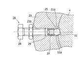
- FIG. 2 is an enlarged cross-sectional view showing a state where the fitting body is fitted to the fitted portion by the fitting adjusting means in the guide wheel device of FIG. 1.
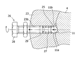
- FIG. 2 is an enlarged cross-sectional view showing a state in which the fitting body is detached from the fitted portion and released from fitting by the fitting adjusting means in the guide wheel device of FIG. 1.
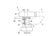
- FIG. 2 is a schematic front view showing a state in which the wheel shaft is rotated using a shaft rotation adjusting jig in the guide wheel device of FIG. 1.
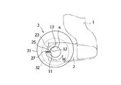
- FIG. 2 is a schematic plan view showing a state where a main guide wheel is in an initial position in the guide wheel device of FIG. 1.
- FIG. 2 is a schematic plan view showing a state in which the main guide wheel is in the next wear adjustment position by rotating the wheel shaft in the guide wheel device of FIG. 1.
- FIG. 2 is a schematic plan view showing a state in which the main guide wheel is in a final wear adjustment position by further rotating the wheel shaft in the guide wheel device of FIG. 1.
- It is a schematic front view which shows the state which rotates a wheel shaft using a shaft rotation adjustment jig in the guide wheel apparatus of the guide rail type vehicle which concerns on 2nd Embodiment of this invention.
- FIG. 9 is a schematic plan view showing a state where the main guide wheel is in an initial position in the guide wheel device of FIG. 8.
- FIG. 9 is a schematic plan view showing a state in which the main guide wheel is in the next wear adjustment position by rotating the wheel shaft in the forward direction in the guide wheel device of FIG. 8.
- FIG. 9 is a schematic plan view showing a state in which the main guide wheel is in the final wear adjustment position by rotating the wheel shaft in the reverse direction in the guide wheel device of FIG. 8.
- FIG. 6 is an enlarged cross-sectional view showing a state in which a fitting body is detached from a fitted portion and released from fitting by a fitting adjusting means in a guide wheel device for a guide rail type vehicle according to a modification of the embodiment of the present invention.
- It is a schematic front view which shows the guide wheel apparatus of the conventional guide rail type vehicle.
- It is a longitudinal cross-sectional view which shows the guide wheel apparatus of the other conventional guide rail type vehicle.
- FIGS. 1 to 7 show a guide wheel device for a guide rail type vehicle according to a first embodiment of the present invention applied to a new transportation system and the like.
- FIG. 1 is a transverse sectional view thereof
- FIG. FIG. 3 is an enlarged cross-sectional view of a state in which the fitting body is fitted to the fitted portion by the adjusting means
- FIG. 3 is an enlarged cross-section in a state in which the fitting body is detached from the fitted portion and released from the fitted portion.
- FIG. 4 is a schematic front view of a state in which the wheel shaft is rotated using the shaft rotation adjusting jig
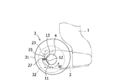
- FIG. 5 is a schematic plan view of the main guide wheel in the initial position
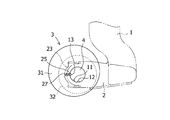
- FIG. FIG. 7 is a schematic plan view of a state where the main guide wheel is in the final wear adjustment position by further rotating the wheel shaft. .
- a guide wheel device for a guide rail type vehicle guides a guide rail installed on each of the left and right sides along a traveling track (guide rail) serving as a route of a new traffic system.
- Guide wheels attached to the front and rear carriages of the rail-type vehicle, and the guide wheels roll in contact with the guide rail so that the guide rail-type vehicle travels while being laterally guided along the travel track. It has become.
- the guide rail is composed of two types of main guide rails and branch guide rails installed in association with each other in the running track, and the main guide rails are installed on both the left and right sides along the running track.
- the guide rail is located in the middle of the traveling track and is installed at a branch point for leading to another traveling track.
- such guide wheel devices are attached to the left and right ends of the front and rear guide transverse beams 1 extending in the vehicle width direction of the guide rail type vehicle, respectively, and the traveling direction of the vehicle is determined.
- a guide arm 2 to be steered is provided, and a guide wheel 3 is rotatably provided at a distal end portion of the guide arm 2 via a wheel shaft 4.
- the guide wheel 3 includes a main guide wheel 31 and a branch guide wheel 32 that are rotatably attached to upper and lower ends of the wheel shaft 4.
- the main guide wheel 31 is disposed above the branch guide wheel 32 so as to be in contact with the side surface of the main guide rail. When the main guide wheel 31 comes into contact with the main guide rail, the main guide wheel 31 has an outer main guide rail.
- a lateral load from the inside toward the inside is applied.
- the branch guide wheel 32 is disposed below the main guide wheel 31 so as to be in contact with the side surface of the branch guide rail.
- the branch guide wheel 32 comes into contact with the branch guide rail, the branch guide wheel 32 has an inner branch.
- a lateral load directed outward from the guide rail is applied.
- the main guide wheel 31 or the branch guide wheel 32 receives a lateral load from the main guide rail or the branch guide rail, so that the guide rail type vehicle can travel on the traveling track of the predetermined operation route. It becomes.
- the guide wheel device has a structure capable of adjusting the wear of the main guide wheel 31, and the main guide wheel 31 has a rotation center C 1 that is offset from the axis C 2 of the wheel shaft 4. It is arranged with a lead. Therefore, the wheel shaft 4 is formed in a crank shape in which an upper and lower intermediate portion is bent halfway, and the intermediate portion is rotatably supported by a bearing 21 attached to the distal end portion of the guide arm 2. That is, in the guide wheel device of the present embodiment, a crankshaft system is adopted in which the inner ring portion of the bearing 21 and the intermediate portion of the wheel shaft 4 are directly assembled.
- the rotation center of the branch guide wheel 32 is arranged at the same position as the axis C2 of the wheel shaft 4.
- a plurality (three in this embodiment) of fitted portions 11, 12, 13 are arranged on the outer peripheral surface of the wheel shaft 4 at predetermined intervals in the circumferential direction. Is provided. These three fitted parts 11, 12, 13 are in the same direction corresponding to the position (first to third) of the wear adjustment amount of the main guide wheel 31 in order to avoid confusion in the adjustment work, They are arranged side by side on the fixed part of the wheel shaft 4 to be rotated, and extend along the axial direction (vertical direction) of the wheel shaft 4.
- the to-be-fitted parts 11, 12, and 13 are V-grooves formed to a depth into which a part of a fitting to be described later enters, and the wall surfaces of the to-be-fitted parts 11, 12, and 13 facing the V-grooves.
- the inclination angles of the wall surfaces 11a, 12a, 13a on the side facing the rotation direction W of the wheel shaft 4 that is the wear adjustment rotation direction of the main guide wheel 31 and pressed by the fitting body described later are It is set to be smaller than the inclination angles of the opposite wall surfaces 11b, 12b, 13b.
- the wall surfaces facing the V-grooves are set at different inclination angles because the first and second fitted parts 11, 12, and the third fitted part 13 are set in this order. It is for making it easy to rotate and to make it the structure which makes it difficult to rotate to a reverse direction, and prevents misadjustment by this.
- a shaft-rotating flange 41 with a hole is provided on the outer periphery of the wheel shaft 4 positioned between the main guide wheel 31 and the bearing 21.
- a plurality of jig fitting holes 41a are disposed in the flange 41 at a predetermined pitch in the circumferential direction, and the tip end portion of the shaft rotation adjusting jig 42 is fitted into the jig fitting holes 41a. It is like that. Therefore, holding the base end side of the shaft rotation adjusting jig 42, the tip end portion of the shaft rotation adjusting jig 42 is fitted into one of the jig fitting holes 41 a to move the wheel shaft 4 in the rotation direction W.
- the wheel shaft 4 When the wheel shaft 4 is turned in the rotation direction W while repeatedly inserting and removing the tip end of the shaft rotation adjusting jig 42 in the jig fitting hole 41a, the wheel shaft 4 is fitted into the desired fit. It will be rotated to the position of the joints 11, 12, and 13.
- the bearing 21 of the present embodiment is configured by fastening and assembling a bearing main body 22 having a screw hole 22a and a bearing lid 23 having a bolt hole 23a with a fastening bolt 24.
- An intermediate portion of the wheel shaft 4 is rotatably supported.
- the fastening bolt 24 is formed in such a length that it can be inserted into the bolt hole 23 a of the bearing lid 23 and screwed into the screw hole 22 a of the bearing body 22 to be tightened.
- a fitting body 25 fitted to the fitted portions 11, 12, 13 provided on the outer peripheral surface of the wheel shaft 4, and the fitting Fitting adjusting means 26 is provided that can press the combined body 25 toward the wheelset 4 toward the fitted parts 11, 12, 13 or release the pressing of the fitting body 25.
- the fitting body 25 is a spherical body (for example, a steel ball) having a size and a shape that can be fitted into the V groove of the fitted portions 11, 12, 13 on the wheel shaft 4 side.
- the fitting adjusting means 26 is positioned between a pressing spring 27 that presses the fitting body 25 toward the wheel shaft 4, a pressing member 28 that presses the pressing spring 27 toward the fitting body 25, and the pressing spring 27 and the pressing member 28.
- the pressing member 28 is configured to advance and retract in the pressing direction by a screw structure. For this reason, through passages 23b each having a female screw threadedly engaged with the male screw portion on the distal end side of the pressing member 28 are formed at two locations above and below the center portion of the bearing lid 23.
- the front end side of the fitting body 25, the pressing spring 27, the spring seat member 29, and the pressing member 28 is movably disposed.
- a part of the fitting body 25 is disposed so as to protrude from the inner peripheral surface of the bearing lid 23 where the through-passage 23 b is provided, and the proximal end side of the pressing member 28 is the outer periphery of the bearing lid 23. It is arranged in a state protruding from the surface.
- the main guide wheel 31 that contacts the main guide rail is worn by the travel of the guide rail type vehicle, and the main guide rail and
- the fastening bolts 24 are loosened without removing the bearing cover 23 from the bearing body 22, and the outer peripheral surface of the wheel shaft 4 and the bearing cover 23 are removed. Leave a slight gap between the inner peripheral surface.
- the pressing member 28 of the fitting adjusting means 26 is slightly loosened, and it is necessary for the fitting body 25 to get over the V groove of the first fitted portion 11 at the initial position shown in FIGS. 1 to 3 and 5.
- a bending allowance is given to the pressing spring 27, and the fitting body 25 is returned to the bearing lid 23 side.
- the tip end portion of the shaft rotation adjusting jig 42 is inserted into the jig fitting hole 41 a of the holed shaft rotation flange 41, and the wheel shaft 4 is rotated in the rotation direction W. Accordingly, when the fitting body 25 gets over the V groove of the first fitted portion 11 and reaches the V groove of the second fitted portion 12 in the next wear adjustment position, the fitting body 25 is fitted by the elastic force of the pressing spring 27. A part of the combined body 25 enters and fits into the V groove of the second fitted portion 12, and the wear adjustment position is determined.
- the fastening bolt 24 of the bearing lid 23 is fastened and fixed to the bearing body 22 and the pressing member 28 is fastened and locked, so that the main guide wheel 31 is eccentric with the position of the wheel shaft 4 fixed. It moves to the main guide rail side by a distance corresponding to the amount, the clearance between the outer peripheral surface of the main guide wheel 31 and the main guide rail becomes appropriate, and the wear adjustment of the main guide wheel 31 is completed (see FIG. 6). . It should be noted that when the second fitted portion 12 shown in FIG. 6 is displaced from the position of the second fitted portion 12 to the third fitted portion 13 at the next wear adjustment position shown in FIG. The wear of the main guide wheel 31 can be adjusted.
- the guide wheel device for a guide rail type vehicle In the guide wheel device for a guide rail type vehicle according to the first embodiment of the present invention, an operation such as removing the bearing lid 23 of the bearing 21 from the bearing body 22 is unnecessary, and the adjustment operation is performed only by loosening the fastening bolt 24. be able to. Further, the wheel shaft 4 can be rotated and locked to the fitted portions 11, 12, 13 at desired positions by operating the fitting adjusting means 26 and the like, and the wear adjustment of the main guide wheel 31 can be easily performed. be able to. Further, after the wear adjustment of the main guide wheel 31, the fitting body 25 enters and fits into the V grooves of the fitted portions 12 and 13 by the elastic force of the pressing spring 27 pressed by the pressing member 28. For this reason, the adjustment position does not change due to vibration while the vehicle is running.
- FIG. 8 to 11 show a guide wheel device for a guide rail type vehicle according to a second embodiment of the present invention applied to a new transportation system.
- FIG. 8 shows a wheel shaft using an axis rotation adjusting jig.
- FIG. 9 is a schematic plan view of the main guide wheel in the initial position
- FIG. 10 is the main guide wheel in the next wear adjustment position by rotating the wheel shaft in the forward direction.
- FIG. 11 is a schematic plan view of a certain state
- FIG. 11 is a schematic plan view of a state in which the main guide wheel is at the final wear adjustment position by rotating the wheel shaft in the reverse direction.
- the second embodiment unlike the first embodiment, as shown in FIGS.
- the next wear adjustment position with respect to the first fitted portion 11 at the initial position provided on the wheel shaft 4 is used.
- the second fitted portion 12 and the third fitted portion 13 at the final wear adjustment position are arranged in the forward / reverse rotation direction. Further, the inclination angles of the wall surfaces 11a, 12a, 13a, 11b, 12b, and 13b on both sides forming the V-grooves of the fitted portions 11, 12, and 13 are the same.
- Other configurations are the same as those of the first embodiment, and the same members are denoted by the same reference numerals.
- the procedure for adjusting the wear of the main guide wheel 31 in the second embodiment is the same as that in the first embodiment except that the rotation direction W of the wheel shaft 4 is rotated in the forward and reverse directions.
- the fitted portions 11, 12, and 13 of the wheel shaft 4 are V-grooves and the fitting body 25 is a sphere, but the fitting and detaching of both can be performed reliably and smoothly.
- the fitted portions 11, 12, 13 may be either arc grooves or conical holes, and instead of the spherical fitting body 25, a shell-like fitting body 25a or cone shown in FIG. Any of the fitting bodies may be used.
- the bearing 21 is divided into the bearing body 22 and the bearing lid 23.
- the guide wheel device of the present invention can be applied to an integral bearing having no bearing lid. Is possible.
- the wheel shaft 4 is of the crankshaft type.
- the guide wheel device of the present invention can be applied to a single-shaft system as shown in FIG. Is possible.
Landscapes
- Engineering & Computer Science (AREA)
- Mechanical Engineering (AREA)
- Transportation (AREA)
- Platform Screen Doors And Railroad Systems (AREA)
Abstract
Description
すると、この回動操作に応じて案内輪軸63が回動し、支持軸68の軸中心C1より距離eだけ偏芯した案内輪軸63の軸中心C2が軸中心C1の周りの変更中心まで移動し、軸中心C2に対する変更中心の案内アーム61の左右方向における変位量相当分、案内輪62が案内アーム61から外側に移動調整される。この移動調整で案内軌条と案内輪62の外周面との隙間が適度となれば、ボルト66を中間部のねじ孔67に螺合させて締め付けて回動レバー65を固定することによって、案内輪62の摩耗調整が完了することになる。
なお、支持軸68の大径案内軸部68aは案内アーム61の上方に配置され、小径取付軸部68bは案内アーム61の取付孔61aに挿通され、下端側の分岐輪軸部68cには分岐輪69が支持されている。
また、従来の案内輪装置は、構造が複雑であるため、保守点検の際に行う分解整備作業が難しく、保守管理費が高くなるという問題があった。
図1~図7は、新交通システムなどに適用する本発明の第1実施形態に係る案内軌条式車両の案内輪装置を示すものであり、図1はその横断面図、図2は嵌合調整手段により嵌
合体を被嵌合部に嵌合させている状態の拡大横断面図、図3は嵌合調整手段により嵌合体を被嵌合部から離脱させて嵌合解除させる状態の拡大横断面図、図4は軸回動調整治具を用いて輪軸を回動させる状態の概略正面図、図5は主案内輪が初期の位置にある状態の概略平面図、図6は輪軸を回動させることにより主案内輪が次の摩耗調整位置にある状態の概略平面図、図7は輪軸をさらに回動させることにより主案内輪が最終の摩耗調整位置にある状態の概略平面図である。
案内レールは、走行軌道において、関連を持たせて設置される2種類の主案内レールと分岐案内レールとから構成されており、主案内レールは、走行軌道に沿って左右両側に設置され、分岐案内レールは、走行軌道の途中に位置して別の走行軌道へ導くための分岐箇所に設置されている。
案内輪3は、輪軸4の上下端部に回転自在に取付けられる主案内輪31と分岐案内輪32とから構成されている。主案内輪31は、分岐案内輪32の上方に位置して主案内レールの側面に接するように配置されており、主案内レールに当接すると、主案内輪31には、外側の主案内レールから内方へ向かう横方向の荷重が加わるようになっている。また、分岐案内輪32は、主案内輪31の下方に位置して分岐案内レールの側面に接するように配置されており、分岐案内レールに当接すると、分岐案内輪32には、内側の分岐案内レールから外方へ向かう横方向の荷重が加わるようになっている。このように、主案内輪31または分岐案内輪32が主案内レールまたは分岐案内レールから横方向の荷重を受けることによって、案内軌条式車両が所定の運行ルートの走行軌道上を走行することが可能となる。
さらに、被嵌合部11,12,13は、後述する嵌合体の一部が入る深さに形成されたV溝であり、各被嵌合部11,12,13のV溝の対向する壁面のうち、主案内輪31の摩耗調整回動方向である輪軸4の回動方向Wに臨む側に位置し、後述の嵌合体が押される側の壁面11a,12a,13aの傾斜角は、その反対側の壁面11b,12b,13bの傾斜角よりもそれぞれ小さく設定されている。このように、V溝の対向する壁面を異なる傾斜角に設定するのは、第1の被嵌合部11、第2の被嵌合部12、第3の被嵌合部13の順に輪軸4を回動し易くし、逆方向へ回動し難くする構造とするためであり、これによって誤調整を防止している。
また、軸受蓋23の中央部の上下2箇所(2箇所以上でも良い)には、輪軸4の外周面に設けた被嵌合部11,12,13に嵌合する嵌合体25と、該嵌合体25を輪軸4側へ向かって被嵌合部11,12,13に押圧し、または嵌合体25の押圧を解除可能な嵌合調整手段26が設けられている。嵌合体25は、輪軸4側の被嵌合部11,12,13のV溝と嵌合可能な大きさ及び形状の球体(例えば、鋼球)である。
次いで、軸回動調整治具42の先端部を、図4に示すように、穴付き軸回動用フランジ41の治具嵌合穴41aに差し込み、輪軸4を回動方向Wへ廻す。これに伴い、嵌合体25は第1被嵌合部11のV溝を乗り越え、次の摩耗調整位置の第2被嵌合部12のV溝まで来ると、押圧バネ27の弾撥力により嵌合体25の一部が当該第2被嵌合部12のV溝内に入り込んで嵌合し、摩耗調整位置が決定する。しかる後、軸受蓋23の締結ボルト24を締付けて軸受本体22に固定するとともに、押圧部材28を締込んでロックすれば、輪軸4の位置が固定された状態で、主案内輪31が偏芯量相当分の距離だけ主案内レール側に移動し、主案内輪31の外周面と主案内レールとの隙間が適度となり、主案内輪31の摩耗調整が完了することになる(図6参照)。
なお、図6に示す第2被嵌合部12の位置から、図7に示す更に次の摩耗調整位置の第3被嵌合部13に変位させる場合も、上記と同様の手順で操作すれば、主案内輪31の摩耗調整を行うことが可能である。
図8~図11は、新交通システムに適用する本発明の第2実施形態に係る案内軌条式車両の案内輪装置を示すものであり、図8は軸回動調整治具を用いて輪軸を回動させる状態の概略正面図、図9は主案内輪が初期の位置にある状態の概略平面図、図10は輪軸を正方向に回動させることにより主案内輪が次の摩耗調整位置にある状態の概略平面図、図11は輪軸を逆方向に回動させることにより主案内輪が最終の摩耗調整位置にある状態の概略平面図である。
この第2実施形態においては、上記第1実施形態と異なり、図8~図11に示すように、輪軸4に設けられる初期位置の第1被嵌合部11に対して、次の摩耗調整位置の第2被嵌合部12と最終摩耗調整位置の第3被嵌合部13とが正逆回動方向に配置されている。また、被嵌合部11,12,13のV溝を形成する両側の壁面11a,12a,13a,11b,12b,13bの傾斜角は同じである。
その他の構成は上記第1実施形態と同様であり、これと同一の部材は同一の符号で示している。また、第2実施形態における主案内輪31の摩耗調整操作手順も、輪軸4の回動方向Wを正逆方向へ回動させる以外、上記第1実施形態と同様である。
2 案内アーム
3 案内輪
4 輪軸
11,12,13 被嵌合部
21 軸受
22 軸受本体
23 軸受蓋
24 締結ボルト
25,25a 嵌合体
26 嵌合調整手段
27 押圧バネ
28 押圧部材
31 主案内輪
32 分岐案内輪
41 穴付き軸回動用フランジ
41a 治具嵌合穴
42 軸回動調整治具
C1 主案内輪の回転中心
C2 輪軸の軸芯
51 走行軌道
52 案内レール
52a 主案内レール
52b 分岐案内レール
53 案内輪
53a 主案内輪
53b 分岐案内輪
54 輪軸
61 案内アーム
62 案内輪
63 案内輪軸
64 キー
65 回動レバー
66 ボルト
67 ネジ孔
68 支持軸
69 分岐輪
Claims (4)
- 軸受に回動可能に支持される輪軸と、該輪軸の上下部に回転自在に取付けられた主案内輪及び分岐案内輪とを備えた案内軌条式車両の案内輪装置において、
前記主案内輪は、その回転中心が前記輪軸の軸芯に対し偏芯し、前記輪軸の外周面には、円周方向に並んで配置された複数の被嵌合部が設けられ、前記軸受には、前記被嵌合部に嵌合する嵌合体が設けられ、該嵌合体を前記輪軸側へ向かって前記被嵌合部に押圧し、または前記嵌合体の押圧を解除可能な嵌合調整手段が設けられていることを特徴とする案内軌条式車両の案内輪装置。 - 前記嵌合調整手段は、前記嵌合体を前記輪軸側へ押圧する押圧バネと、該押圧バネを前記嵌合体側に押圧する押圧部材とを備え、該押圧部材は、ネジ構造によって押圧方向に進退するように構成されていることを特徴とする請求項1に記載の案内軌条式車両の案内輪装置。
- 前記被嵌合部がV溝、円弧溝、円錐穴のいずれかであり、前記嵌合体が前記V溝、円弧溝、円錐穴と嵌合可能な球体、砲弾状体、円錐体のいずれかであることを特徴とする請求項1または2に記載の案内軌条式車両の案内輪装置。
- 前記V溝、円弧溝、円錐穴の各々の壁面のうち、前記輪軸の回動方向に臨む前記嵌合体が押される側の壁面の傾斜角が、その反対側の壁面の傾斜角よりも小さいことを特徴とする請求項3に記載の案内軌条式車両の案内輪装置。
Priority Applications (5)
| Application Number | Priority Date | Filing Date | Title |
|---|---|---|---|
| HK12111309.9A HK1170456B (en) | 2009-10-14 | 2009-12-24 | Guide wheel device for guide rail vehicle |
| KR1020127008078A KR101340665B1 (ko) | 2009-10-14 | 2009-12-24 | 안내 궤조식 차량의 안내륜 장치 |
| US13/498,170 US8833828B2 (en) | 2009-10-14 | 2009-12-24 | Guide wheel device for guide rail vehicle |
| SG2012018065A SG179138A1 (en) | 2009-10-14 | 2009-12-24 | Guide wheel device for guide rail vehicle |
| CN200980161723.7A CN102548771B (zh) | 2009-10-14 | 2009-12-24 | 导向轨条式车辆的导向轮装置 |
Applications Claiming Priority (2)
| Application Number | Priority Date | Filing Date | Title |
|---|---|---|---|
| JP2009-237048 | 2009-10-14 | ||
| JP2009237048A JP5145308B2 (ja) | 2009-10-14 | 2009-10-14 | 案内軌条式車両の案内輪装置 |
Publications (1)
| Publication Number | Publication Date |
|---|---|
| WO2011045871A1 true WO2011045871A1 (ja) | 2011-04-21 |
Family
ID=43875928
Family Applications (1)
| Application Number | Title | Priority Date | Filing Date |
|---|---|---|---|
| PCT/JP2009/071385 Ceased WO2011045871A1 (ja) | 2009-10-14 | 2009-12-24 | 案内軌条式車両の案内輪装置 |
Country Status (7)
| Country | Link |
|---|---|
| US (1) | US8833828B2 (ja) |
| JP (1) | JP5145308B2 (ja) |
| KR (1) | KR101340665B1 (ja) |
| CN (1) | CN102548771B (ja) |
| SG (1) | SG179138A1 (ja) |
| TW (1) | TW201113180A (ja) |
| WO (1) | WO2011045871A1 (ja) |
Families Citing this family (2)
| Publication number | Priority date | Publication date | Assignee | Title |
|---|---|---|---|---|
| JP5730381B1 (ja) | 2013-12-12 | 2015-06-10 | 三菱重工業株式会社 | 案内輪、走行台車、及び車両 |
| CN104527320A (zh) * | 2014-12-30 | 2015-04-22 | 苏州路云机电设备有限公司 | 一种带锁定装置的双边轮 |
Citations (4)
| Publication number | Priority date | Publication date | Assignee | Title |
|---|---|---|---|---|
| JPH0230772U (ja) * | 1988-08-22 | 1990-02-27 | ||
| JP2582980Y2 (ja) * | 1993-12-27 | 1998-10-15 | 株式会社神戸製鋼所 | デュアルモード車両等の案内装置における案内輪支持装置 |
| JP3314343B2 (ja) * | 1995-08-04 | 2002-08-12 | ダイムラークライスラー・アクチエンゲゼルシヤフト | 環状体の位置の可変な端面締付け装置 |
| JP2003146204A (ja) * | 2001-11-13 | 2003-05-21 | Niigata Eng Co Ltd | 案内軌条式車両用台車の案内輪支持装置 |
Family Cites Families (10)
| Publication number | Priority date | Publication date | Assignee | Title |
|---|---|---|---|---|
| US1206583A (en) * | 1916-05-27 | 1916-11-28 | John Palley | Car-axle. |
| JPH0230772A (ja) | 1988-07-21 | 1990-02-01 | Stanley Electric Co Ltd | 超微粒子膜形成用スプレーノズル |
| JP2876096B2 (ja) | 1992-11-06 | 1999-03-31 | 川崎重工業株式会社 | 台車のゲージ変更方法および可変ゲージ台車ならびにゲージ変更設備 |
| JP3357167B2 (ja) | 1993-05-26 | 2002-12-16 | 松下電工株式会社 | 繊維強化プラスチックの製造方法 |
| WO2000020269A1 (en) * | 1998-10-02 | 2000-04-13 | Daimlerchrysler Ag | Guide wheel assembly |
| CN2536424Y (zh) | 2002-01-30 | 2003-02-19 | 无锡市蓝力机床有限公司 | 偏心可调式导向滚轮 |
| TWI291447B (en) | 2003-12-26 | 2007-12-21 | Murata Machinery Ltd | Track guided vehicle system |
| DE102004014413B4 (de) * | 2004-03-18 | 2006-06-08 | Walter Sobolewski | Schienenweg für Fahrzeuge mit unterschiedlichen Fortbewegungsmitteln und Antriebssystemen sowie Fahrzeug zum Befahren des Schienenweges |
| CN201002617Y (zh) | 2007-02-15 | 2008-01-09 | 天津赛瑞机器设备有限公司 | 一种偏心轴翼轮轨道车 |
| CN201183118Y (zh) | 2008-04-18 | 2009-01-21 | 中国有色(沈阳)冶金机械有限公司 | 一种可调导向轮同轨道间隙的装置 |
-
2009
- 2009-10-14 JP JP2009237048A patent/JP5145308B2/ja active Active
- 2009-12-24 SG SG2012018065A patent/SG179138A1/en unknown
- 2009-12-24 CN CN200980161723.7A patent/CN102548771B/zh active Active
- 2009-12-24 KR KR1020127008078A patent/KR101340665B1/ko not_active Expired - Fee Related
- 2009-12-24 WO PCT/JP2009/071385 patent/WO2011045871A1/ja not_active Ceased
- 2009-12-24 US US13/498,170 patent/US8833828B2/en active Active
-
2010
- 2010-01-05 TW TW099100096A patent/TW201113180A/zh unknown
Patent Citations (4)
| Publication number | Priority date | Publication date | Assignee | Title |
|---|---|---|---|---|
| JPH0230772U (ja) * | 1988-08-22 | 1990-02-27 | ||
| JP2582980Y2 (ja) * | 1993-12-27 | 1998-10-15 | 株式会社神戸製鋼所 | デュアルモード車両等の案内装置における案内輪支持装置 |
| JP3314343B2 (ja) * | 1995-08-04 | 2002-08-12 | ダイムラークライスラー・アクチエンゲゼルシヤフト | 環状体の位置の可変な端面締付け装置 |
| JP2003146204A (ja) * | 2001-11-13 | 2003-05-21 | Niigata Eng Co Ltd | 案内軌条式車両用台車の案内輪支持装置 |
Also Published As
| Publication number | Publication date |
|---|---|
| US20120181805A1 (en) | 2012-07-19 |
| CN102548771A (zh) | 2012-07-04 |
| TW201113180A (en) | 2011-04-16 |
| JP2011084127A (ja) | 2011-04-28 |
| US8833828B2 (en) | 2014-09-16 |
| CN102548771B (zh) | 2014-08-20 |
| HK1170456A1 (en) | 2013-03-01 |
| JP5145308B2 (ja) | 2013-02-13 |
| TWI373422B (ja) | 2012-10-01 |
| KR20120048030A (ko) | 2012-05-14 |
| SG179138A1 (en) | 2012-04-27 |
| KR101340665B1 (ko) | 2013-12-11 |
Similar Documents
| Publication | Publication Date | Title |
|---|---|---|
| KR101580418B1 (ko) | 철도 차량용 조타 대차 | |
| US9291223B2 (en) | Axle assembly having a steering knuckle | |
| KR101264073B1 (ko) | 차륜 허브 조인트 유닛 | |
| US20080227581A1 (en) | Axle housing with differential bearing support | |
| US20120241230A1 (en) | Suspension element for self-propelled machine | |
| KR20020004963A (ko) | 가이드웨이 차량용 조향장치 및 방법 | |
| EP1559631A1 (en) | Steering system | |
| JP5145308B2 (ja) | 案内軌条式車両の案内輪装置 | |
| JP4125508B2 (ja) | 案内軌条式車両用台車の案内輪支持装置 | |
| US20200284299A1 (en) | Torque Transmission Shaft | |
| US11982319B2 (en) | Torque transmission shaft | |
| CN111094114A (zh) | 带有转向功能的轮毂单元和具有它的车辆 | |
| KR101408396B1 (ko) | 궤도식 차량 | |
| US20180194427A1 (en) | Steered wheel support structure of vehicle | |
| HK1170456B (en) | Guide wheel device for guide rail vehicle | |
| JP2023500180A (ja) | シングルトラック自動車用の前輪ガイド | |
| JP2007055538A (ja) | 懸架装置の支持構造 | |
| JP2009517267A (ja) | 枢着装置の組立のための方法及び自動車軸のための枢着装置 | |
| JP2018128077A (ja) | ヨークとシャフトの結合構造 | |
| JPS6136722Y2 (ja) | ||
| JP2007332696A (ja) | 転てつ減摩器 | |
| JP2008162356A (ja) | 車輪用軸受装置 | |
| JPH035351B2 (ja) | ||
| HK1181356B (en) | Guide rail type vehicle | |
| JP2007247826A (ja) | 車輪用軸受装置 |
Legal Events
| Date | Code | Title | Description |
|---|---|---|---|
| WWE | Wipo information: entry into national phase |
Ref document number: 200980161723.7 Country of ref document: CN |
|
| 121 | Ep: the epo has been informed by wipo that ep was designated in this application |
Ref document number: 09850412 Country of ref document: EP Kind code of ref document: A1 |
|
| WWE | Wipo information: entry into national phase |
Ref document number: 13498170 Country of ref document: US |
|
| ENP | Entry into the national phase |
Ref document number: 20127008078 Country of ref document: KR Kind code of ref document: A |
|
| NENP | Non-entry into the national phase |
Ref country code: DE |
|
| 122 | Ep: pct application non-entry in european phase |
Ref document number: 09850412 Country of ref document: EP Kind code of ref document: A1 |