WO2011043374A1 - 排ガス処理方法及び排ガス処理装置 - Google Patents
排ガス処理方法及び排ガス処理装置 Download PDFInfo
- Publication number
- WO2011043374A1 WO2011043374A1 PCT/JP2010/067545 JP2010067545W WO2011043374A1 WO 2011043374 A1 WO2011043374 A1 WO 2011043374A1 JP 2010067545 W JP2010067545 W JP 2010067545W WO 2011043374 A1 WO2011043374 A1 WO 2011043374A1
- Authority
- WO
- WIPO (PCT)
- Prior art keywords
- reaction
- exhaust gas
- temperature
- gas treatment
- agent
- Prior art date
- Legal status (The legal status is an assumption and is not a legal conclusion. Google has not performed a legal analysis and makes no representation as to the accuracy of the status listed.)
- Ceased
Links
Images

Classifications
-
- B—PERFORMING OPERATIONS; TRANSPORTING
- B01—PHYSICAL OR CHEMICAL PROCESSES OR APPARATUS IN GENERAL
- B01D—SEPARATION
- B01D53/00—Separation of gases or vapours; Recovering vapours of volatile solvents from gases; Chemical or biological purification of waste gases, e.g. engine exhaust gases, smoke, fumes, flue gases, aerosols
- B01D53/34—Chemical or biological purification of waste gases
- B01D53/46—Removing components of defined structure
- B01D53/68—Halogens or halogen compounds
- B01D53/685—Halogens or halogen compounds by treating the gases with solids
-
- B—PERFORMING OPERATIONS; TRANSPORTING
- B01—PHYSICAL OR CHEMICAL PROCESSES OR APPARATUS IN GENERAL
- B01D—SEPARATION
- B01D53/00—Separation of gases or vapours; Recovering vapours of volatile solvents from gases; Chemical or biological purification of waste gases, e.g. engine exhaust gases, smoke, fumes, flue gases, aerosols
- B01D53/02—Separation of gases or vapours; Recovering vapours of volatile solvents from gases; Chemical or biological purification of waste gases, e.g. engine exhaust gases, smoke, fumes, flue gases, aerosols by adsorption, e.g. preparative gas chromatography
- B01D53/04—Separation of gases or vapours; Recovering vapours of volatile solvents from gases; Chemical or biological purification of waste gases, e.g. engine exhaust gases, smoke, fumes, flue gases, aerosols by adsorption, e.g. preparative gas chromatography with stationary adsorbents
- B01D53/0407—Constructional details of adsorbing systems
- B01D53/0438—Cooling or heating systems
-
- B—PERFORMING OPERATIONS; TRANSPORTING
- B01—PHYSICAL OR CHEMICAL PROCESSES OR APPARATUS IN GENERAL
- B01D—SEPARATION
- B01D53/00—Separation of gases or vapours; Recovering vapours of volatile solvents from gases; Chemical or biological purification of waste gases, e.g. engine exhaust gases, smoke, fumes, flue gases, aerosols
- B01D53/34—Chemical or biological purification of waste gases
- B01D53/46—Removing components of defined structure
- B01D53/68—Halogens or halogen compounds
- B01D53/70—Organic halogen compounds
-
- B—PERFORMING OPERATIONS; TRANSPORTING
- B01—PHYSICAL OR CHEMICAL PROCESSES OR APPARATUS IN GENERAL
- B01D—SEPARATION
- B01D2251/00—Reactants
- B01D2251/40—Alkaline earth metal or magnesium compounds
- B01D2251/404—Alkaline earth metal or magnesium compounds of calcium
-
- B—PERFORMING OPERATIONS; TRANSPORTING
- B01—PHYSICAL OR CHEMICAL PROCESSES OR APPARATUS IN GENERAL
- B01D—SEPARATION
- B01D2251/00—Reactants
- B01D2251/60—Inorganic bases or salts
- B01D2251/602—Oxides
-
- B—PERFORMING OPERATIONS; TRANSPORTING
- B01—PHYSICAL OR CHEMICAL PROCESSES OR APPARATUS IN GENERAL
- B01D—SEPARATION
- B01D2251/00—Reactants
- B01D2251/60—Inorganic bases or salts
- B01D2251/604—Hydroxides
-
- B—PERFORMING OPERATIONS; TRANSPORTING
- B01—PHYSICAL OR CHEMICAL PROCESSES OR APPARATUS IN GENERAL
- B01D—SEPARATION
- B01D2253/00—Adsorbents used in seperation treatment of gases and vapours
- B01D2253/10—Inorganic adsorbents
- B01D2253/112—Metals or metal compounds not provided for in B01D2253/104 or B01D2253/106
- B01D2253/1124—Metal oxides
-
- B—PERFORMING OPERATIONS; TRANSPORTING
- B01—PHYSICAL OR CHEMICAL PROCESSES OR APPARATUS IN GENERAL
- B01D—SEPARATION
- B01D2253/00—Adsorbents used in seperation treatment of gases and vapours
- B01D2253/30—Physical properties of adsorbents
- B01D2253/302—Dimensions
- B01D2253/304—Linear dimensions, e.g. particle shape, diameter
-
- B—PERFORMING OPERATIONS; TRANSPORTING
- B01—PHYSICAL OR CHEMICAL PROCESSES OR APPARATUS IN GENERAL
- B01D—SEPARATION
- B01D2253/00—Adsorbents used in seperation treatment of gases and vapours
- B01D2253/30—Physical properties of adsorbents
- B01D2253/302—Dimensions
- B01D2253/311—Porosity, e.g. pore volume
-
- B—PERFORMING OPERATIONS; TRANSPORTING
- B01—PHYSICAL OR CHEMICAL PROCESSES OR APPARATUS IN GENERAL
- B01D—SEPARATION
- B01D2257/00—Components to be removed
- B01D2257/20—Halogens or halogen compounds
- B01D2257/204—Inorganic halogen compounds
- B01D2257/2047—Hydrofluoric acid
-
- B—PERFORMING OPERATIONS; TRANSPORTING
- B01—PHYSICAL OR CHEMICAL PROCESSES OR APPARATUS IN GENERAL
- B01D—SEPARATION
- B01D2257/00—Components to be removed
- B01D2257/20—Halogens or halogen compounds
- B01D2257/206—Organic halogen compounds
- B01D2257/2066—Fluorine
-
- B—PERFORMING OPERATIONS; TRANSPORTING
- B01—PHYSICAL OR CHEMICAL PROCESSES OR APPARATUS IN GENERAL
- B01D—SEPARATION
- B01D2258/00—Sources of waste gases
- B01D2258/02—Other waste gases
- B01D2258/0216—Other waste gases from CVD treatment or semi-conductor manufacturing
Definitions
- the present invention relates to an exhaust gas treatment method and an exhaust gas treatment apparatus for reacting and removing harmful gas components contained in exhaust gas discharged from a semiconductor device manufacturing apparatus with a solid reaction remover.
- This application claims priority based on Japanese Patent Application No. 2009-233368 for which it applied to Japan on October 7, 2009, and uses the content here.
- inert gases such as argon (Ar), krypton (Kr), xenon (Xe), and helium (He) in addition to gas, CF 4, C 2 F 6 , C 3 F 8, C 4 F 6, C 4 F 8, C 5 F 8, CHF 3, C 2 HF 5, SiHCl 3, HCl, BCl 3, AsH
- fluorocarbons such as 3 , PH 3 , H 2 Se, SiH 4 are used as process gases.
- Perfluorocarbons hereinafter referred to as “PFCs”
- HFCs hydrofluorocarbons contained in the exhaust gas discharged from these semiconductor manufacturing processes are greenhouse gases having a very high global warming potential. From the viewpoint of preventing global warming, it is strongly desired to reduce its emissions.
- a method of processing by converting fluorocarbon into carbon dioxide (CO 2 ) or hydrogen fluoride (HF) by combustion or plasma is widely used.
- process exhaust gas is introduced into a combustion field generated with fuel such as propane, and the components to be treated are decomposed by a high-temperature flame.
- fuel such as propane
- a large amount of fuel is consumed or accompanied by combustion.
- NOx nitrogen oxides
- the process exhaust gas is converted into plasma using high-frequency and high-voltage electricity, and the component to be treated is decomposed with the energy (see, for example, Patent Documents 1, 2, and 3).
- plasma can be generated instantaneously, so there is an advantage that wasteful energy consumption can be reduced without requiring standby discharge, but in the case of process exhaust gas treatment where the composition always changes, the timing for waiting However, since the operating rate is increased as a result, the power consumed for plasma generation, that is, the CO 2 equivalent emission amount increases, which is a problem from the viewpoint of preventing global warming.
- the decomposition treatment is performed after adding an oxidizing agent such as O 2 or H 2 O, and the stabilization treatment is performed with a water scrubber after the decomposition.
- the fluoric acid waste liquid generated by the water scrubber is strongly acidic, and its processing requires a great deal of danger and labor.
- an object of the present invention is to provide an exhaust gas treatment method and an exhaust gas treatment device that can reduce the power consumption of the entire exhaust gas treatment device.
- an exhaust gas treatment method of the present invention is an exhaust gas treatment method for reacting and removing harmful gas components contained in exhaust gas discharged from a semiconductor manufacturing apparatus with a solid reaction remover.
- At least one of the outer wall surface temperature measuring unit for measuring the outer wall surface temperature and the reaction removing agent temperature measuring unit for measuring the temperature of the reaction removing agent is provided at three locations in the gas flow direction of the reaction removing agent filling cylinder.
- at least one of the outer wall surface heating means for heating the outer wall surface of the reaction removal agent-filled cylinder and the reaction removal agent heating means for heating the reaction removal agent is provided on the reaction removal agent-filled cylinder.
- the position of the reaction zone in the reaction removal agent-filled cylinder is detected based on the temperature measured by each temperature measuring means, Characterized by controlling each heating means based, the temperature measuring means and the heating means, the interval for the gas flow direction of the reaction removing agent filled barrel may in the range of each 50 ⁇ 500 mm.
- the exhaust gas treatment apparatus of the present invention measures the outer wall surface temperature of the reaction removal agent-filled cylinder in the exhaust gas treatment apparatus that reacts and removes harmful gas components contained in the exhaust gas discharged from the semiconductor manufacturing apparatus with a solid reaction removal agent.
- the position of the reaction zone in the reaction removal agent-filled cylinder is detected based on the temperature measured by each temperature measuring means, and each heating method is determined based on the position of the reaction zone. Characterized in that it comprises a heating control means for controlling the temperature measuring means and the heating means, the interval for the gas flow direction of the reaction removing agent filled barrel may be in the range of each 50 ⁇ 500 mm.
- the present invention it is possible to reduce the power source power that wasted by heating the site where the reaction removal agent that does not contribute to the reaction is heated, so that the power consumption of the exhaust gas treatment device can be minimized, contributing to the prevention of global warming. can do.
- An exhaust gas treatment apparatus 1 shown in FIG. 1 processes exhaust gas from a semiconductor manufacturing apparatus 2 such as a reactive plasma etching apparatus or a fluorocarbon thin film chemical vapor deposition apparatus, and the exhaust gas is discharged from the semiconductor manufacturing apparatus 2 to an exhaust pump. 3 is introduced into the exhaust gas treatment device 1.
- a semiconductor manufacturing apparatus 2 such as a reactive plasma etching apparatus or a fluorocarbon thin film chemical vapor deposition apparatus
- the exhaust gas treatment apparatus 1 includes a reaction removal agent filling cylinder 12 filled with a solid reaction removal agent 11 for reacting with a specific harmful gas component contained in the exhaust gas to remove the specific harmful gas component, and a reaction removal
- a heater controller 15 for controlling the operation and a plurality of reaction removal agent temperature monitors 16 for measuring the temperature of the reaction removal agent 11 are provided.
- a filter 17 that prevents the reaction remover 11 from leaking is provided at the bottom of the reaction remover-filled cylinder 12.
- the reaction removal agent filling cylinder 12 is normally detachably attached to the upstream and downstream pipes by a flange or the like so that the reaction removal agent 11 inside can be exchanged as necessary. It is desirable to adjust the pressure in the reaction removal agent-filled cylinder 12 in the range of 1 kPa to atmospheric pressure.
- the pipe 18 on the upstream side of the reaction removal agent filling cylinder 12 connecting between the exhaust pump 3 and the upper part of the reaction removal agent filling cylinder 12 has a structure capable of maintaining a pressure at which the exhaust pump 3 can operate normally.
- the pipe 18 preferably has a larger diameter, and more preferably has a diameter of 10 mm or more.
- the exhaust gas to be treated contains a component having a deposition property such as C 2 F 4 , it is desirable to keep the pressure in the pipe 18 low and raise the pipe surface temperature. Furthermore, it is desirable to select a material with high durability against fluoride and to perform surface treatment to improve durability against fluoride. For example, stainless steel pipes subjected to fluorine passivation treatment etc. may be used. it can.
- a dry pump having high corrosion resistance can be used as the exhaust pump 3.
- a general dry pump uses a large amount of nitrogen gas as a purge gas for diluting the suction gas and a shaft seal gas, but the pump can reduce the amount of nitrogen gas to less than 3 liters per minute, preferably 1 liter per minute or less. It is desirable to use By reducing the flow rates of the purge gas and the shaft seal gas, the flow rate in the reaction removal agent filling cylinder 12 is suppressed, the contact probability between the removal target component and the reaction removal agent 11 is improved, and the energy required for heating is suppressed. it can.
- harmful gas components to be removed include C 2 F 4 , C 4 F 6 , C 5 F 8 , C 2 H 2 F 2 , C 2 HF 3 , C 3 HF 5 , C 3 H 2 F 4 and the like.
- a reaction removal agent hereinafter referred to as “Ca removal agent” mainly composed of a calcium compound such as calcium oxide or calcium hydroxide is used.
- the Ca removing agent contains 90% by weight or more of calcium oxide or calcium hydroxide, and this Ca removing agent is usually formed by rolling, tableting, or extruding calcium oxide or calcium hydroxide, or a mixture of both.
- This Ca removing agent is usually formed by rolling, tableting, or extruding calcium oxide or calcium hydroxide, or a mixture of both.
- the particle size of the Ca removing agent is less than 0.5 mm, it is difficult to fill the reaction removing agent-filled cylinder 12 with a porosity of 30% by volume or more and hinder gas flow. It becomes difficult to control.
- the particle size of the Ca removing agent exceeds 10 mm, it becomes difficult to fill the reaction removing agent filling cylinder 12 with a porosity of 70% by volume or less, and the contact probability between the harmful gas component and the reactant becomes low.
- the Ca removal agent does not sufficiently react to the grain center.
- Fluorocarbon having an unsaturated bond is removed by reacting with a Ca removing agent, but it is known that only a small part reacts when the temperature of the atmosphere in which both are in contact is about 10 to 30 ° C. This is because the activation energy is high. In order to promote the reaction, it is necessary to apply energy such as temperature as disclosed in Patent Document 5.
- reaction heat is generated in the reaction between the harmful gas component and the reaction removing agent. Specifically, it can be calculated by comparing the free energy of each generation. That is, the reaction can be efficiently promoted by applying the minimum necessary thermal energy exceeding the activation energy to the initial stage of the reaction by the heater 14.
- the concentration of the harmful gas component in the treatment target gas is caused by the reaction between the reaction removal agent 11 and the harmful gas component. It decreases continuously from the upstream side in the gas flow direction of the removing agent filling cylinder 12. That is, the upstream reaction removal agent 11 is exposed to a higher concentration of harmful gas components, causing a more efficient reaction and an increase in temperature due to reaction heat. That is, in the reaction zone, the temperature of the reaction remover 11 is higher than the outer wall surface temperature of the reaction remover-filled cylinder 12 provided by the heater 14. Similarly, the reaction zone has a certain distribution in the length direction of the reaction removal agent filling cylinder 12. Such chemical reactions are greatly affected by the flow rate, flow rate and coexisting components, and it is difficult to clarify the reaction mechanism.
- the semiconductor manufacturing apparatus 2 includes, for example, Ar, Kr, Xe, CF 4 , C 2 F 6 , C 3 F 8 , C 4 F 6 , C 4 F 8 , C 5 F 8 , CHF 3 , C 2 HF 5.
- Such gas is introduced as process gas.
- the introduced gas is exhausted as exhaust gas as it is, and plasma or heating is performed in the semiconductor manufacturing apparatus 2.
- a gas containing C 2 F 4 , COF 2 , CO, CO 2 , HF, SiF 4 and the like is discharged as an exhaust gas during the step (hereinafter “treatment process”).
- treatment process Part of the exhaust gas during the treatment process maintains an excited active state and exists as an active species such as a radical.
- Fluorocarbons that are saturated with bonds such as CF 4 , C 2 F 6 , and C 3 F 8 are very stable, and thus pass through the reaction removal agent-filled cylinder 12 without reacting with the reaction removal agent 11.
- a part of other harmful gas components reacts with the reaction remover 11 such as the Ca remover and is removed.
- the fluoride gas that maintains the excited state is also removed by reacting with the reaction removing agent 11.
- calcium oxide is considered to react more easily than calcium hydroxide having a relatively large free energy of formation, but it is hydrolyzable like COF 2 or SiF 4 .
- calcium hydroxide (Ca (OH) 2 ) on the surface of calcium oxide serves as a reaction factor, and thus a reaction represented by the following formula occurs.
- reaction removal agent 11 When a mixed agent of calcium oxide and calcium hydroxide is used as the reaction removal agent 11, the water generated by the reaction reacts with the surrounding calcium oxide to produce calcium hydroxide as a new reaction factor. It is possible to reduce the influence of moisture release on the downstream side of the agent filling cylinder.
- fluorocarbons having unsaturated bonds of C 2 F 4 , C 4 F 6 , and C 5 F 8 give calcium oxide (CaO) as shown in the following formula by applying thermal energy of about 200 to 400 ° C. React with.
- the gas derived from the exhaust gas treatment apparatus 1 is a gas having a fluoride gas concentration lower than that of the process exhaust gas and containing only relatively stable components. Since the fluoride gas concentration is low, by disposing the exhaust gas treatment device as shown in this embodiment before the high-efficiency PFC decomposition / removal device aiming at thorough reduction of PFC emissions, PFC decomposition This can contribute to a reduction in the amount of energy required for processing. In addition, since unstable components are removed, this exhaust gas treatment device is arranged upstream of the recovery device for the purpose of recovery and reuse of PFC or rare gas, thereby facilitating separation and purification.
- the exhaust gas treatment device 1 can contribute and can be suitably used as a pretreatment device for a high-efficiency PFC decomposition and removal device, a PFC recovery device, and a rare gas recovery device.
- C 2 F 4 , C 4 F 6 , and C 5 F 8 are removed by reaction, it is not necessary to prevent deposits on the downstream pipe of the exhaust gas treatment apparatus 1. That is, only the pipe 18 between the exhaust pump 3 and the exhaust gas treatment apparatus 1 needs to be heated to prevent deposits.
- the temperature of the pipe 18 is desirably about 120 to 180 ° C.
- the reaction remover-filled cylinder 12 that causes such a reaction
- the reaction remover is replaced with as much reaction remover as possible for the purpose of reducing the replacement frequency of the reaction remover, that is, maintenance, so that the total length of the cylinder is 1000 mm or more.
- the length of the reaction zone is generally designed to fall within the range of 1 to 500 mm, although it varies depending on the type of harmful gas component and reaction removing agent, the concentration of the component to be removed, and the flow rate.
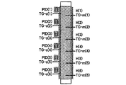
- a plurality of cylinder surface temperature monitors 13, a heater 14, a heater controller 15 and a reaction removal agent temperature monitor 16 are connected to the reaction removal agent filling cylinder 12.
- the cylinder surface temperature monitor 13, the heater 14, the heater controller 15, and the reaction removal agent temperature monitor 16 are arranged one by one in each divided part.
- a set of temperature control units 19 is configured for each part.
- the number of the temperature control units 19, that is, the number of divisions of the reaction removal agent filling cylinder 12 is a condition such as the length (height) or diameter of the reaction removal agent filling cylinder 12 in the gas flow direction, the internal gas flow rate, the reaction state, Usually, it is set to 3 or more, preferably 5 or more, and the length of the divided portion in the gas flow direction of the reaction removal agent-filled cylinder 12 is 500 mm or less, preferably Is preferably 300 mm or less. If the number of divisions of the reaction removal agent-filled cylinder 12 is 2 or the length of the division part exceeds 500 mm, the effect of arranging a plurality of temperature control parts 19 cannot be obtained sufficiently.
- TC-c (x) for the cylinder surface temperature monitor 13 in the region (division part) where the reaction zone is proceeding
- H (x) for the heater 14 PID (x) for the heater controller 15, reaction remover
- TC-m (x) shows a higher value than TC-c (x) due to the influence of reaction heat.
- the position of the belt can be grasped. Therefore, a signal is sent from the TC-m (x) that detects the arrival of the reaction zone to the heater controller PID (x + 1) on the downstream side to operate the heater H (x + 1) and the heater control on the upstream side
- a signal is sent to the device PID (x-1) to operate the heater H (x-1).
- PID (x + 1) controls the heater H (x + 1) so that TC-c (x + 1) becomes a predetermined temperature optimized in the range of 200 to 400 ° C.
- the PID (x-1) controls the heater H (x-1) so that TC-c (x-1) becomes a predetermined temperature optimized in the range of 120 to 180 ° C, or the heater Set H (x-1) to OFF.
- x is a natural number of 1 or more, and represents the order of the regions from the upstream side in the gas flow direction in the reaction removal agent filling cylinder 12.
- the position of the reaction zone is detected based on the measured temperature of the cylinder surface temperature monitor 13 and the measured temperature of the reaction remover temperature monitor 16 that change with the progress of the reaction zone, and corresponds to the detected position of the reaction zone.
- the heater 14 is operated to heat the reaction remover 11 to the reaction start temperature
- the removal reaction is performed by maintaining the temperature in order to prevent the formation of deposits in the division unit in which the temperature control unit 19 is disposed.
- each divided portion on the upstream side through which the reaction zone has passed in order to prevent deposits from being formed.
- the length of the divided portion and the progress of the reaction zone are required.
- one or more downstream divisions may be heated to a preset temperature of the reaction removal agent 11 immediately before the reaction zone arrives. 14 can be put into a standby state without operating. That is, as in the prior art, uniformly heating the entire reaction removal agent-filled cylinder 12 to a preset temperature is heating an excessive region, and wastes power supply power for the heater. For this reason, it is possible to save energy by reducing the heat energy applied to other than the reaction zone where the harmful gas component and the reaction removing agent 11 react.
- the component by-produced by the reaction between the reaction remover 11 and the harmful gas component has a property of efficiently reacting with the reaction remover 11 in a high temperature atmosphere, for example, calcium oxide (CaO) and carbonyl fluoride (COF) 2
- CO 2 is by-produced by the reaction with 2
- the entire reaction removal agent-filled cylinder 12 is heated in advance as in the prior art, CaO and CO 2 react to become CaCO 3 , CaO which is a reaction removal agent is wasted by CO 2 which is a by-product gas, and the removal efficiency of harmful gas components is reduced.
- the reaction remover 11 is prevented from being wasted by reacting with the by-product gas, and the reaction remover. 11 can be effectively used for reaction removal of harmful gas components.
- the reaction removal agent filling cylinder 12 can be excessively charged.
- temperature rise can be prevented. Specifically, by comparing the cylinder surface temperature and the reaction removal agent temperature in the same region, or the upstream reaction removal agent temperature and the downstream reaction removal agent temperature, the harmful gas component and the reaction removal agent are compared. It is possible to detect signs of excessive exothermic reaction, and at the same time, control to suppress the amount of heat input from the heater prevents waste of power supply for the heater and prevents excessive temperature rise of the reaction removal agent filling cylinder It is possible to achieve both.
- Example 1 A fluorocarbon thin film CVD apparatus using C 5 F 8 and Ar as process gases was used as the semiconductor manufacturing apparatus 2, and the exhaust gas from the semiconductor manufacturing apparatus 2 was introduced into the exhaust gas processing apparatus 1 via the exhaust pump 3.
- the pipe 18 from the exhaust pump 3 to the exhaust gas treatment apparatus 1 was made of stainless steel and heated so that the pipe surface temperature was 150 ° C.
- the main composition of the exhaust gas introduced into the exhaust gas treatment device 1 is Ar: 55%, C 5 F 8 : 15%, C 2 F 4 : 24%, C 2 F 6 : 3%, CF 4 : 2%. there were.
- a stainless steel cylinder having an inner diameter of 150 mm and a length of 1800 mm was used as the reaction removal agent filling cylinder 12, and 20 kg of granular calcium oxide having a particle diameter of about 2 to 6 mm was filled therein so that the porosity was 50% by volume.
- the exhaust gas treatment apparatus 1 divides the length direction of the reaction removing agent-filled cylinder 12 into six portions of 300 mm each, and the temperature control unit 19 is provided in each divided unit. All temperature sensors used K-type thermocouples.
- H (1) as the heater 14 was operated using the PID (1) as the heater controller 15 so that the TC-c (1) as the cylinder surface temperature monitor 13 would be 300 ° C. .
- the TC-c is detected by the PID (2) located one downstream side.
- H (2) was operated so that (2) was 300 ° C.
- H (3) is operated so that TC-c (3) becomes 300 ° C. by PID (3). The same control was repeated until (6) was operated.
- H (1) is operated by PID (1) so that TC-c (1) becomes 150 ° C., and thereafter H ( The same control was repeated until 5) was operated.
- the heater which makes the reaction remover-filled cylinder surface temperature 300 ° C. was suppressed to 1/3 of the whole.
- the remaining 2/3 was room temperature at the start of the experiment and 150 ° C. at the end of the experiment.
- the power consumption could be reduced by 50% compared to 3600 Wh when the whole was always heated to 300 ° C.
- the ratio of CaF 2 contained in the reaction removal agent after the end of the experiment could be improved from 40 wt% when the whole was heated to 300 ° C. to 60 wt%.
- the harmful gas components contained in the gas discharged from the exhaust gas treatment apparatus 1 were only CF 4 , C 2 F 6 , C 3 F 8 and CO.
- the gas exhausted from the exhaust gas treatment device 1 is introduced into a plasma generator that generates inductively coupled plasma (ICP) using a 2 MHz high frequency power source, and decomposed, A process of introducing degradable organisms into granular calcium oxide was performed. As a result, the overall fluorocarbon removal efficiency was found to exceed 99.9%.
- the power of the high frequency power source at this time was 2 kW.
- Example 2 A fluorocarbon thin film CVD apparatus using C 5 F 8 and Ar as process gases was used as the semiconductor manufacturing apparatus 2, and the exhaust gas from the semiconductor manufacturing apparatus 2 was introduced into the exhaust gas processing apparatus 1 via the exhaust pump 3.
- the pipe 18 from the exhaust pump 3 to the exhaust gas treatment apparatus 1 was made of stainless steel and heated so that the pipe surface temperature was 150 ° C.
- the main composition of the exhaust gas introduced into the exhaust gas treatment apparatus 1 is Ar: 55%, C 5 F 8 : 15%, C 2 F 4 : 24%, C 2 F 6 : 3%, CF 4 : 2%. there were.
- a stainless steel cylinder having an inner diameter of 250 mm and a length of 1200 mm was used as the reaction removal agent filling cylinder 12, and 37 kg of granular calcium oxide having a particle diameter of about 2 to 6 mm was filled therein so that the porosity was 50% by volume.
- the exhaust gas treatment apparatus 1 divides the length direction of the reaction removal agent-filled cylinder 12 into 200 mm by six, and a temperature control unit 19 is provided in each divided part. All temperature sensors used K-type thermocouples.
- H (1) was operated using PID (1) so that TC-c (1) would be 300 ° C.
- H (2) is set so that TC-c (2) becomes 300 ° C by PID (2). Made it work.
- H (3) is operated so that TC-c (3) becomes 300 ° C. by PID (3). The same control was repeated until (6) was operated. Further, when the temperature of TC-m (2) rises to 400 ° C.
- H (1) is operated by PID (1) so that TC-c (1) becomes 150 ° C., and thereafter H ( The same control was repeated until 5) was operated.
- the heater which makes the reaction remover-filled cylinder surface temperature 300 ° C. was suppressed to 1/3 of the whole.
- the remaining 2/3 was room temperature at the start of the experiment and 150 ° C. at the end of the experiment.
- the power consumption can be reduced by 50% compared to 7800 Wh when the whole is always heated to 300 ° C.
- the proportion of CaF 2 contained in the reaction removal agent after the end of the experiment could be improved from 40% by weight to 60% by weight when the whole was always heated to 300 ° C.
- Example 3 A fluorocarbon thin film CVD apparatus using C 5 F 8 and Ar as process gases was used as the semiconductor manufacturing apparatus 2, and the exhaust gas from the semiconductor manufacturing apparatus 2 was introduced into the exhaust gas processing apparatus 1 via the exhaust pump 3.
- the pipe 18 from the exhaust pump 3 to the exhaust gas treatment apparatus 1 was made of stainless steel and heated so that the pipe surface temperature was 150 ° C.
- the main composition of the exhaust gas introduced into the exhaust gas treatment apparatus 1 is Ar: 55%, C 5 F 8 : 15%, C 2 F 4 : 24%, C 2 F 6 : 3%, CF 4 : 2%. there were.
- a stainless steel cylinder having an inner diameter of 150 mm and a length of 1800 mm was used as the reaction removal agent-filled cylinder 12, and 20 kg of granular calcium oxide having a particle diameter of about 2 to 6 mm was filled therein so that the porosity was 50% by volume.
- the exhaust gas treatment apparatus 1 divides the length direction of the reaction removing agent-filled cylinder 12 into six portions of 300 mm each, and a temperature control unit 19 is provided in each divided portion. All temperature sensors used K-type thermocouples.
- H (1) was operated using PID (1) so that TC-c (1) was 200 ° C.
- H (2) is set so that TC-c (2) becomes 200 ° C by PID (2). Made it work.
- H (3) is operated by PID (3) so that TC-c (3) becomes 200 ° C. The same control was repeated until (6) was operated. Further, when the temperature of TC-m (2) rises to 280 ° C.
- H (1) is operated by PID (1) so that TC-c (1) becomes 150 ° C., and thereafter H ( The same control was repeated until 5) was operated.
- the heater for setting the reaction removing agent-filled cylinder surface temperature to 200 ° C. was suppressed to 1/3 of the whole.
- the remaining 2/3 was room temperature at the start of the experiment and 150 ° C. at the end of the experiment.
- the power consumption can be reduced by 40% compared to 1800 Wh when the whole is always heated to 200 ° C.
- Example 4 Based on the conditions of Example 1, when the temperature of TC-m (x) rises to 400 ° C. or higher, the set temperature TC-c (x ⁇ 1) for operating H (x ⁇ 1) is set to 100 ° C. Experiments were performed at 120 ° C, 180 ° C, and 200 ° C. The heater which makes the reaction removal agent filling cylinder surface temperature 300 degreeC was restrained to 1/3 of the whole. The remaining 2/3 were at room temperature at the start of the experiment and at 100 ° C., 120 ° C., 180 ° C., and 200 ° C. at the end of the experiment, respectively.
- the effect of reducing power consumption is 55% when TC-c (x-1) is set to 100 ° C compared to the case where the entire temperature is always 300 ° C (3600 Wh), and TC-c (x-1 ) At 120 ° C., 53%, TC-c (x-1) at 180 ° C., 47%, and TC-c (x-1) at 200 ° C., 44%.
- TC-c (x-1) is 100 ° C., a deposit of fluorocarbon is generated after the removal process is completed, so TC-c (x-1) should be set to 120 ° C. or higher. I understand that.
Landscapes
- Chemical & Material Sciences (AREA)
- Engineering & Computer Science (AREA)
- Analytical Chemistry (AREA)
- General Chemical & Material Sciences (AREA)
- Oil, Petroleum & Natural Gas (AREA)
- Chemical Kinetics & Catalysis (AREA)
- Health & Medical Sciences (AREA)
- Biomedical Technology (AREA)
- Environmental & Geological Engineering (AREA)
- Treating Waste Gases (AREA)
Abstract
本発明は、排ガス処理装置全体の消費電力を低減することができる排ガス処理方法及び排ガス処理装置を提供する。具体的に本発明の排ガス処理方法は、半導体製造装置から排出される排ガスに含まれる有害ガス成分を固体の反応除去剤で反応除去する排ガス処理方法であって、前記反応除去剤の温度を測定する手段および前記反応除去剤を加熱する手段のそれぞれを前記反応除去剤充填筒のガス流れ方向の3箇所以上に設けていること、各温度測定手段にて測定した温度に基づいて反応除去剤充填筒内の反応帯の位置を検知し、前記反応帯の位置に基づいて各加熱手段を制御することを特徴とする。
Description
本発明は、半導体装置の製造装置から排出される排ガスに含まれる有害ガス成分を固体の反応除去剤で反応除去するための排ガス処理方法及び排ガス処理装置に関する。
本願は、2009年10月7日に日本に出願された特願2009-233368号に基づき優先権を主張し、その内容をここに援用する。
本願は、2009年10月7日に日本に出願された特願2009-233368号に基づき優先権を主張し、その内容をここに援用する。
ドライエッチング、薄膜化学気相成長(CVD)、CVDチャンバクリーニングなどのプラズマを利用する半導体製造プロセスにおいては、アルゴン(Ar),クリプトン(Kr),キセノン(Xe),ヘリウム(He)などの不活性ガスの他に、CF4,C2F6,C3F8,C4F6,C4F8,C5F8,CHF3,C2HF5,SiHCl3,HCl,BCl3,AsH3,PH3,H2Se,SiH4などのフルオロカーボンを含む多種多様な化合物がプロセスガスとして使用される。これらの半導体製造プロセスから排出される排ガスに含まれるパーフルオロカーボン類(以下、「PFCs」)やハイドロフルオロカーボン類(以下、「HFCs」)は、温暖化係数が非常に高い温室効果ガスであり、地球温暖化防止の観点からその排出量の削減が強く望まれている。
フルオロカーボンを含むプロセス排ガスの処理方法としては、例えば、燃焼やプラズマによってフルオロカーボンを二酸化炭素(CO2)やフッ化水素(HF)に変換して処理する方法が広く用いられている。燃焼を利用した処理方法は、プロセス排ガスをプロパンなどの燃料で生成した燃焼場に導入し、高温火炎によって処理対象成分を分解するものであるが、多量の燃料を消費することや、燃焼に伴って多量のCO2や窒素酸化物(NOx)が発生することなどが問題とされている。プラズマを利用した処理方法は、高周波・高電圧の電気を利用してプロセス排ガスをプラズマ化し、そのエネルギーで処理対象成分を分解するものである(例えば、特許文献1,2,3参照。)。通常、プラズマは瞬時に生成できるため、待機中の放電を必要とせず、無駄な消費エネルギーを削減することができるというメリットを有するが、常に組成が変化するプロセス排ガス処理の場合は、待機させるタイミングが難しく、結果として稼働率が高くなることから、プラズマ生成に消費する電力、すなわちCO2換算排出量が多くなってしまい、地球温暖化防止の観点から課題とされている。
また、いずれの方法においても、分解生成物がプラズマチャンバの内壁面などに堆積物を形成したり、再結合によってPFCs、主にCF4やC2F4が形成されるのを防止することを目的として、O2やH2Oなどの酸化剤を添加してから分解処理するとともに、分解後に水スクラバーによる安定化処理を行うようにしている。水スクラバーによって生じるフッ素酸廃液は強酸性であり、その処理に多大な危険性と労力が必要であるため、半導体工場の大きな課題の一つとされている。
また、近年、資源枯渇の観点から、これらをフッ素の原料となる蛍石として回収する方法が注目されているが、CF4,C2F6,C3F8のような飽和フルオロカーボンは非常に安定であるため、特にCF4をカルシウム化合物(以下、「Ca化合物」)で反応処理する場合には1500℃もの高い温度にする必要があり、膨大なヒーター用電源電力が必要であった。酸化アルミニウムを利用してフッ化アルミニウムを生成させる手段(例えば、特許文献4参照)も提案されているが、1000℃程度は必要であり、エネルギー効率が十分に改善されたとはいえない。さらに、生成するフッ化アルミニウムからフッ素を取り出すことが非常に困難であるという課題もある。
このような背景から、比較的容易に反応する成分のみを、Ca化合物を主剤とする乾式剤で反応除去する方法が提示されており、200~500℃に加熱したCa化合物を主剤とする乾式剤を用いてC2F4などの不飽和フルオロカーボンのみを反応除去する方法が提示されている(例えば、特許文献5参照。)。さらに、HF,COF2及びプラズマプロセスチャンバで与えられたエネルギーを保持した弱励起状態の成分をCa化合物で反応除去し、除去されなかったCF4,C2F6,C3F8のような飽和フルオロカーボンのみをプラズマ分解した後に、プラズマの下流側に別途配置されたCa化合物で反応除去し、プラズマ分解に必要なエネルギーを最小化する方法も提示されている(例えば、特許文献6参照)。
上述の各従来技術により、水処理を不要とし、かつ、比較的低いエネルギーでプロセス排ガス中のフルオロカーボンを除去できることが示されているが、実際の排ガス処理装置として使用する場合のエネルギー効率については検討が不十分であった。すなわち、不飽和結合を持つフルオロカーボンとCa化合物との反応を生じさせるためには、熱エネルギーを与えるヒーター用の電源電力が必要であるが、特許文献5では、実機サイズにおける消費電力の最小化が十分に検討されていないという課題があった。また、特許文献6では、初段のCa化合物で不飽和結合を持つフルオロカーボンを除去することに関する検証が不十分であった。さらに、AsH3、PH3、H2Seなどは、酸化銅などのCu化合物を用いて反応除去する方法が知られているが、反応工程における温度制御については、反応熱による過剰な温度上昇を抑制すること以外は、検討されていない。排ガス処理装置全体の消費電力を最小化することは、地球温暖化防止対策を進める上で必要不可欠であり、実機サイズにおける検証が必要である。
そこで本発明は、排ガス処理装置全体の消費電力を低減することができる排ガス処理方法及び排ガス処理装置を提供することを目的としている。
上記目的を達成するため、本発明の排ガス処理方法は、半導体製造装置から排出される排ガスに含まれる有害ガス成分を固体の反応除去剤で反応除去する排ガス処理方法において、反応除去剤充填筒の外壁面温度を測定する外壁面温度測定手段及び前記反応除去剤の温度を測定する反応除去剤温度測定手段の少なくともいずれか一方の温度測定手段を前記反応除去剤充填筒のガス流れ方向の3箇所以上に設けるとともに、前記反応除去剤充填筒の外壁面を加熱する外壁面加熱手段及び前記反応除去剤を加熱する反応除去剤加熱手段の少なくともいずれか一方の加熱手段を前記反応除去剤充填筒のガス流れ方向の3箇所以上に設け、各温度測定手段にて測定した温度に基づいて反応除去剤充填筒内の反応帯の位置を検知し、前記反応帯の位置に基づいて各加熱手段を制御することを特徴とし、前記温度測定手段及び前記加熱手段は、前記反応除去剤充填筒のガス流れ方向に対する間隔がそれぞれ50~500mmの範囲であると良い。
また、本発明の排ガス処理装置は、半導体製造装置から排出される排ガスに含まれる有害ガス成分を固体の反応除去剤で反応除去する排ガス処理装置において、反応除去剤充填筒の外壁面温度を測定する外壁面温度測定手段及び前記反応除去剤の温度を測定する反応除去剤温度測定手段の少なくともいずれか一方の温度測定手段を前記反応除去剤充填筒のガス流れ方向の3箇所以上に設けるとともに、前記反応除去剤充填筒の外壁面を加熱する外壁面加熱手段及び前記反応除去剤を加熱する反応除去剤加熱手段の少なくともいずれか一方の加熱手段を前記反応除去剤充填筒のガス流れ方向の3箇所以上に設け、各温度測定手段にて測定した温度に基づいて反応除去剤充填筒内の反応帯の位置を検知し、前記反応帯の位置に基づいて各加熱手段を制御する加熱制御手段を備えていることを特徴とし、前記温度測定手段及び前記加熱手段は、前記反応除去剤充填筒のガス流れ方向に対する間隔がそれぞれ50~500mmの範囲であると良い。
本発明によれば、反応に寄与しない反応除去剤の充填部位の加熱に浪費されていた電源電力を削減できるため、排ガス処理装置の消費電力を極小にすることができ、地球温暖化防止に貢献することができる。
図1に示す排ガス処理装置1は、例えば、反応性プラズマエッチング装置やフルオロカーボン薄膜化学気相成長装置などの半導体製造装置2からの排ガスを処理するもので、排ガスは、半導体製造装置2から排気ポンプ3を介して排ガス処理装置1に導入される。
排ガス処理装置1は、排ガス中に含まれる特定の有害ガス成分と反応してこの特定の有害ガス成分を除去するための固体の反応除去剤11を充填した反応除去剤充填筒12と、反応除去剤充填筒12の外壁面温度を測定する複数の筒表面温度モニター13と、反応除去剤充填筒12の表面を加熱することによって反応除去剤11を加熱する複数のヒーター14と、各ヒーター14の動作を制御するヒーター制御器15と、反応除去剤11の温度を測定する複数の反応除去剤温度モニター16とを備えている。また、反応除去剤充填筒12の底部には反応除去剤11の漏出を防止するフィルター17が設けられている。
反応除去剤充填筒12は、通常は、上流側及び下流側の配管に対してフランジなどにより着脱自在に取り付け、内部の反応除去剤11を必要に応じて交換できるように形成している。この反応除去剤充填筒12内の圧力は、1kPaから大気圧の範囲に調整することが望ましい。
また、排気ポンプ3と反応除去剤充填筒12の上部との間を接続する反応除去剤充填筒12の上流側の配管18は、排気ポンプ3が正常に動作できる圧力を維持できる構造であればよく、一般的には、この配管18は、直径が太い方が好ましく、更に好ましくは直径10mm以上であることが望まれる。
また、処理対象となる排ガス中にC2F4のように堆積性を有する成分が含まれている場合は、配管18内の圧力を低く保ち、配管表面温度を高くすることが望ましい。さらに、フッ化物に対する耐久性が高い材質を選択し、フッ化物に対する耐久性を向上させる表面処理を施すことが望ましく、一例として、フッ素不動態化処理などを施したステンレス配管などを使用することができる。
排気ポンプ3としては、耐食性の高いドライポンプなどを利用することができる。また、一般的なドライポンプは、吸入ガスを希釈するパージガス及び軸シールガスとして大量の窒素ガスを用いているが、窒素ガス量を毎分3リットル未満、好ましくは毎分1リットル以下にできるポンプを利用することが望ましい。パージガス及び軸シールガスを少流量化することにより、反応除去剤充填筒12内の流速が抑えられ、除去対象成分と反応除去剤11との接触確率が向上するとともに、加熱に必要なエネルギーを抑制できる。さらには、排ガス処理装置1を通過したガス中に含まれるCF4などの安定な成分を分解・除去したり、回収・精製したりする操作が容易になる。また、半導体製造装置2に、スクリューブースターポンプなど、圧縮比が大きく、数kPa程度の背圧でも正常に動作できるポンプがターボ分子ポンプの代わりに使用されている場合は、これを排気ポンプとして利用することができる。
前記反応除去剤11としては、除去対象となる有害ガス成分に対応したものを用いることができる。例えば、除去対象となる有害ガス成分が、C2F4,C4F6,C5F8,C2H2F2,C2HF3,C3HF5,C3H2F4などの不飽和結合を持つフルオロカーボンの場合は、酸化カルシウムや水酸化カルシウムなどのカルシウム化合物を主成分とする反応除去剤(以下、「Ca除去剤」という)を用いる。
Ca除去剤は、酸化カルシウムや水酸化カルシウムを90重量%以上含むものであって、このCa除去剤は、通常、酸化カルシウム又は水酸化カルシウム、あるいは両者の混合物を、転造や打錠、押出し成形などにより、粒径が0.5~10mmの範囲の顆粒状、粒状の形態に成形されたものを使用し、反応除去剤充填筒12内に空隙率30~70体積%で充填し、排ガスの流れが阻害されないようにすることが好ましい。Ca除去剤の粒径が0.5mm未満では、反応除去剤充填筒12に空隙率30体積%以上で充填することが困難となってガスの流れを阻害するため、励起部の圧力を所定値にコントロールすることが困難になる。また、Ca除去剤の粒径が10mmを超えると、反応除去剤充填筒12に空隙率70体積%以下で充填することが困難となって有害ガス成分と反応剤との接触確率が低くなり、Ca除去剤の粒中心まで十分に反応しなくなる。また、酸化カルシウムは、粒状の水酸化カルシウムを焼成して水分を飛ばし、その内部に微細な空孔が形成されたものを使用することが好ましい。
不飽和結合を持つフルオロカーボンは、Ca除去剤と反応して除去されるが、両者が接触する雰囲気の温度が10~30℃程度の場合は、ごく一部しか反応しないことが知られている。これは活性化エネルギーが高いためであり、反応を促進するためには、特許文献5に開示されている通り、温度などのエネルギーを与える必要がある。
一方で、前記フルオロカーボンとCa除去剤との組み合わせ、あるいは、AsH3、PH3、H2Seなどの水素化物とCu除去剤(銅化合物を主成分とする反応除去剤)との組み合わせのように、有害ガス成分と反応除去剤との反応においては、反応熱が発生することが知られている。詳しくは、それぞれの生成自由エネルギーの比較より算出することが可能である。つまり、活性化エネルギーを超える程度の必要最低限の熱エネルギーをヒーター14によって反応初期に与えることで、効率よく反応を促進することができる。
また、反応除去剤を充填した反応除去剤充填筒12に処理対象ガス(排ガス)を導入すると、反応除去剤11と有害ガス成分との反応によって処理対象ガス中の有害ガス成分の濃度は、反応除去剤充填筒12のガス流れ方向上流側から連続的に減少する。すなわち、上流側の反応除去剤11ほど高濃度の有害ガス成分に曝され、より効率よく反応が生じるとともに、反応熱による温度上昇が生じる。つまり、反応帯においては、ヒーター14で与えられた反応除去剤充填筒12の外壁面温度よりも反応除去剤11の温度の方が高くなる。同様に、反応帯は、反応除去剤充填筒12の長さ方向にある程度の分布を持っている。このような化学反応は、流量、流速及び共存成分の影響が大きく、反応メカニズムを明確することは困難である。
前記半導体製造装置2には、例えばAr、Kr、Xe、CF4、C2F6、C3F8、C4F6、C4F8、C5F8、CHF3、C2HF5などのガスがプロセスガスとして導入される。また、半導体製造装置2内の圧力を安定化させるステップ(以下、「安定化工程」)中は、導入されたガスがそのまま排ガスとして排気され、半導体製造装置2内でプラズマや加熱などが施されるステップ(以下、「処理工程」)中は、前記ガスのほかに、C2F4、COF2、CO、CO2、HF、SiF4などを含むガスが排ガスとして排出される。処理工程中の排ガスの一部は、励起された活性な状態を保ち、ラジカルなどの活性種として存在している。
これらの排ガスは、排気ポンプ3を介して、排ガス処理装置1へと導出される。排ガスに含まれるCF4、C2F4、C2F6、C3F8、C4F6、C4F8、C5F8、COF2、CHF3、C2HF5、HF、SiF4などのフッ化物ガスが除去すべき有害ガス成分である。なお、半導体製造装置2の種類によっては、これ以外の有害ガス成分、例えば、AsH3、PH3、B2H6、GeH4などが排ガス中に含まれる場合がある。このような排ガス中に含まれる有害ガス成分の総量は、半導体製造装置2の種類やプロセスによるが、体積比で0.1~25%程度である。
CF4、C2F6、C3F8のように結合飽和しているフルオロカーボンは非常に安定であるため、反応除去剤11と反応せずにそのまま反応除去剤充填筒12を通過するが、その他の有害ガス成分の一部は、前記Ca除去剤などの反応除去剤11と反応して除去される。同時に、励起状態を維持するフッ化物ガスも反応除去剤11と反応して除去される。Ca除去剤の場合、一般的には、生成自由エネルギーが比較的に負に大きい水酸化カルシウムよりも酸化カルシウムの方が反応しやすいと考えられるが、COF2やSiF4のように加水分解性を有する成分の場合は、酸化カルシウム表面の水酸化カルシウム(Ca(OH)2)が反応因子となるため、以下の式で示される反応を生じる。
SiF4+2Ca(OH)2 → 2CaF2+SiO2+2H2O
COF2+Ca(OH)2 → CaF2+CO2+H2O
COF2+Ca(OH)2 → CaF2+CO2+H2O
なお、酸化カルシウムと水酸化カルシウムとの混合剤を反応除去剤11として使用すると、反応によって生じた水分が周辺の酸化カルシウムと反応し、新たな反応因子である水酸化カルシウムを生じるため、反応除去剤充填筒下流側への水分放出影響を小さくすることができる。
一方、C2F4、C4F6、C5F8の不飽和結合を持つフルオロカーボンは、200~400℃程度の熱エネルギーを与えることで、以下の式に示す通り、酸化カルシウム(CaO)と反応する。
C2F4+2CaO → 2CaF2+2CO
C4F6+3CaO → 3CaF2+3CO+C
C5F8+4CaO → 4CaF2+4CO+C
C4F6+3CaO → 3CaF2+3CO+C
C5F8+4CaO → 4CaF2+4CO+C
このように、有害ガス成分の主な成分であるフッ化物は、フッ化カルシウム(蛍石)として固定される。したがって、排ガス処理装置1から導出されるガスは、プロセス排ガスよりもフッ化物ガス濃度が低く、かつ、比較的安定した成分のみが含まれたガスであると言える。フッ化物ガス濃度が低くなることから、PFC排出量の徹底的な削減を目的とした高効率PFC分解除去装置の前段に本形態例で示すような排ガス処理装置を配置することで、PFCの分解処理に必要なエネルギー量の低減に貢献することができる。また、不安定な成分が除去されることから、この排ガス処理装置を、PFCあるいは希ガスの回収再利用を目的とした回収装置の前段に配置することで、分離及び精製を容易にすることに貢献でき、排ガス処理装置1は、高効率PFC分解除去装置やPFC回収装置、希ガス回収装置の前処理装置として好適に使用することが可能である。
また、C2F4、C4F6、C5F8が反応除去されるため、排ガス処理装置1の下流側の配管には堆積物の予防を施す必要がなくなる。つまり、排気ポンプ3と排ガス処理装置1との間の前記配管18にのみ、堆積物予防としての配管加熱を行えばよいことになる。なお、配管18の温度は、120~180℃程度にすることが望ましい。
このような反応を生じる反応除去剤充填筒12においては、反応除去剤の交換頻度、即ちメンテナンスを少なくする目的で、極力多くの反応除去剤を充填するため、筒の全長が1000mm以上になることが少なくない。しかしながら、有害ガス成分や反応除去剤の種類、被除去成分の濃度及び流速によっても異なるが、反応帯の長さは、一般的には1~500mmの範囲内に収まるように設計されている。
このように設計されている反応除去剤充填筒12において、本形態例では、複数の筒表面温度モニター13、ヒーター14、ヒーター制御器15及び反応除去剤温度モニター16を、反応除去剤充填筒12をガス流れ方向に対して複数に分割した状態で、各分割部に筒表面温度モニター13、ヒーター14、ヒーター制御器15及び反応除去剤温度モニター16をそれぞれ一つずつ配置することにより、各分割部毎に一組の温度制御部19を構成している。
温度制御部19の配置数、即ち反応除去剤充填筒12の分割数は、反応除去剤充填筒12のガス流れ方向の長さ(高さ)や直径、内部のガス流速、反応状態などの条件に基づいて設定されるものであり、通常は、3分割以上、好ましくは5分割以上とすることが好ましく、反応除去剤充填筒12のガスの流れ方向における分割部の長さは500mm以下、好ましくは300mm以下とすることが好ましい。反応除去剤充填筒12の分割数が2であったり、分割部の長さが500mmを超えたりすると、温度制御部19を複数配置する効果を十分に得られなくなる。逆に、反応除去剤充填筒12の分割数を多くして分割部の長さを短くした場合、例えば、分割部の長さを50mm未満とした場合は、分割数を多くしたことによる効果の向上を得られにくく、温度制御部19の数が増えて各機器に要するコストが増大して初期コストの負担や保守に要するコストの負担が大きくなってしまうことがある。
ここで、反応帯が進行している領域(分割部)の筒表面温度モニター13をTC-c(x)、ヒーター14をH(x)、ヒーター制御器15をPID(x)、反応除去剤温度モニター16をTC-m(x)としたとき、反応熱の影響で、TC-m(x)はTC-c(x)よりも高い値を示すことから、この物理現象を利用して反応帯の位置を把握することができる。したがって、反応帯が到達したことを検知したTC-m(x)から一つ下流側のヒーター制御器PID(x+1)に信号を送ってヒーターH(x+1)を動作させるとともに、上流側のヒーター制御器PID(x-1)に信号を送ってヒーターH(x-1)を動作させる。この時、PID(x+1)は、TC-c(x+1)が200~400℃の範囲で最適化された所定の温度になるようにヒーターH(x+1)を制御する。また、PID(x-1)は、TC-c(x-1)が120~180℃の範囲で最適化された所定の温度になるようにヒーターH(x-1)を制御するか、ヒーターH(x-1)をOFFにする。なお、xは1以上の自然数であって、反応除去剤充填筒12におけるガス流れ方向上流側からの領域の順番を表している。
すなわち、反応帯の進行に伴って変化する筒表面温度モニター13の測定温度と反応除去剤温度モニター16の測定温度とに基づいて反応帯の位置を検知し、検知した反応帯の位置に対応する温度制御部19に対して、これから反応帯が進行していく一つ下流側に位置する温度制御部19では、ヒーター14を作動させて反応開始温度になるように反応除去剤11を加熱するととともに、反応帯が通過した一つ上流側に位置する温度制御部19では、該温度制御部19が配置された分割部内で堆積物が生じるのを予防するための温度維持を行うことにより、除去反応に必要な最小限の熱エネルギーを与えることで有害ガス成分と反応除去剤11とを効率よく反応させることができる。
したがって、反応帯が通過した上流側の各分割部は、堆積物が生じるのを予防するためだけの加熱を行えばよく、反応帯が進行する下流側では、分割部の長さや反応帯の進行速度に応じて一つ乃至複数の下流側の各分割部を、反応帯が到達する直前に反応除去剤11をあらかじめ設定した温度に加熱しておけばよく、反応帯が接近するまでは、ヒーター14を作動させずに待機状態としておくことができる。つまり、従来のように、反応除去剤充填筒12の全体をあらかじめ設定した温度に均一に加熱することは、過剰な領域を加熱することであり、ヒーター用の電源電力を浪費していることに相当することから、有害ガス成分と反応除去剤11とが反応する反応帯以外に与える熱エネルギーを削減することで、省エネルギー化を図ることが可能となる。
また、反応除去剤11と有害ガス成分との反応によって副生成される成分が高温雰囲気下で反応除去剤11と効率よく反応する性質を持つ場合、例えば酸化カルシウム(CaO)とフッ化カルボニル(COF2)との反応でCO2が副生成する場合などは、従来のように、反応除去剤充填筒12の全体があらかじめ加熱されていると、CaOとCO2とが反応してCaCO3となり、反応除去剤であるCaOが副生成ガスであるCO2によって浪費され、有害ガス成分の除去効率が低下してしまう。これに対して、前述のように、必要な部分の反応除去剤のみを加熱するようにしたことにより、反応除去剤11が副生成ガスと反応して浪費されることが抑制され、反応除去剤11を有害ガス成分の反応除去に効果的に利用することができる。
さらに、ガス流れ方向の複数領域で、筒表面温度の測定及び反応除去剤温度の測定とヒーターの制御とを行うため、反応帯の進行を確認できるだけでなく、反応除去剤充填筒12の過剰な温度上昇を予防できるという利点がある。具体的には、同じ領域の筒表面温度と反応除去剤温度、あるいは、上流側の反応除去剤温度と下流側の反応除去剤温度とを比較することで、有害ガス成分と反応除去剤との過剰な発熱反応の兆候を検知することができ、これと同時にヒーターからの入熱量を抑制する制御を行うことにより、ヒーター用電源電力の浪費防止と、反応除去剤充填筒の過剰な温度上昇予防とを両立することが可能となる。
以下、実施例により本発明をさらに詳しく説明するが、本発明はこれらに限定されるものではない。
(実施例1)
C5F8及びArをプロセスガスとするフルオロカーボン薄膜用CVD装置を半導体製造装置2として使用し、この半導体製造装置2の排ガスを、排気ポンプ3を介して排ガス処理装置1に導入した。なお、排気ポンプ3から排ガス処理装置1までの配管18はステンレス鋼製とし、配管表面温度が150℃になるように加温した。排ガス処理装置1に導入される排ガスの主な組成は、Ar:55%、C5F8:15%、C2F4:24%、C2F6:3%、CF4:2%であった。
C5F8及びArをプロセスガスとするフルオロカーボン薄膜用CVD装置を半導体製造装置2として使用し、この半導体製造装置2の排ガスを、排気ポンプ3を介して排ガス処理装置1に導入した。なお、排気ポンプ3から排ガス処理装置1までの配管18はステンレス鋼製とし、配管表面温度が150℃になるように加温した。排ガス処理装置1に導入される排ガスの主な組成は、Ar:55%、C5F8:15%、C2F4:24%、C2F6:3%、CF4:2%であった。
反応除去剤充填筒12として、内径150mm、長さ1800mmのステンレス製の円筒体を用い、内部に粒径約2~6mmの粒状酸化カルシウムを20kg、空隙率50体積%となるように充填した。排ガス処理装置1は、図2に示す通り、反応除去剤充填筒12の長さ方向を300mmずつに6分割し、各分割部に温度制御部19をそれぞれ設けた。温度センサーは全てK型熱電対を使用した。
実験開始時は、筒表面温度モニター13であるTC-c(1)が300℃になるようにヒーター制御器15であるPID(1)を用いてヒーター14であるH(1)を動作させた。排ガス処理を継続している途中、反応除去剤温度モニター16であるTC-m(1)の温度が400℃以上に上昇した時点で、一つ下流側に位置するPID(2)によってTC-c(2)が300℃になるようにH(2)を動作させた。同様に、TC-m(2)の温度が400℃以上に上昇した時点で、PID(3)によってTC-c(3)が300℃になるようにH(3)を動作させ、以降、H(6)を動作させるまで、同様の制御を繰り返した。
また、TC-m(2)の温度が400℃以上に上昇した時点で、PID(1)によってTC-c(1)が150℃になるようにH(1)を動作させ、以降、H(5)を動作させるまで、同様の制御を繰り返した。以上の制御を用いることにより、反応除去剤充填筒表面温度を300℃にするヒーターは、全体の1/3に抑えられた。残りの2/3は、実験開始時が室温であり、実験終了時が150℃であった。消費電力は、常に全体を300℃に加熱する場合の3600Whと比較して50%削減できた。さらに、実験終了後の反応除去剤に含まれるCaF2の割合は、常に全体を300℃に加熱する場合の40重量%から60重量%に改善できた。
なお、排ガス処理装置1から排出されるガス中に含まれる有害ガス成分は、CF4、C2F6、C3F8及びCOのみであった。本実施例1では、これら排ガス処理装置1から排出されたガスを、2MHz高周波電源を使用する誘導結合型プラズマ(ICP:Inductively Coupled Plasma)を発生するプラズマ発生装置に導入して分解処理し、さらに分解性生物を粒状酸化カルシウム剤に導入する処理を行った。その結果、全体としてフルオロカーボン除去効率は99.9%を超えることがわかった。このときの高周波電源の電力は2kWであった。一方、同じプロセスを行った半導体製造装置2の排ガスを、排ガス処理装置1を通さずにプラズマ発生装置に直接導入して処理すると、高周波電源電力を3kWとしても安定なプラズマが得られず、フルオロカーボン除去効率も50%以下であった。
(実施例2)
C5F8及びArをプロセスガスとするフルオロカーボン薄膜用CVD装置を半導体製造装置2として使用し、前記半導体製造装置2の排ガスを排気ポンプ3を介して排ガス処理装置1に導入した。なお、排気ポンプ3から排ガス処理装置1までの配管18はステンレス鋼製とし、配管表面温度が150℃になるように加温した。排ガス処理装置1に導入された排ガスの主な組成は、Ar:55%、C5F8:15%、C2F4:24%、C2F6:3%、CF4:2%であった。反応除去剤充填筒12として、内径250mm、長さ1200mmのステンレス製の円筒体を用い、内部に粒径約2~6mmの粒状酸化カルシウムを37kg、空隙率50体積%となるように充填した。排ガス処理装置1は、図2に示す通り、反応除去剤充填筒12の長さ方向を200mmずつに6分割し、各分割部に温度制御部19をそれぞれ設けた。温度センサーは全てK型熱電対を使用した。
C5F8及びArをプロセスガスとするフルオロカーボン薄膜用CVD装置を半導体製造装置2として使用し、前記半導体製造装置2の排ガスを排気ポンプ3を介して排ガス処理装置1に導入した。なお、排気ポンプ3から排ガス処理装置1までの配管18はステンレス鋼製とし、配管表面温度が150℃になるように加温した。排ガス処理装置1に導入された排ガスの主な組成は、Ar:55%、C5F8:15%、C2F4:24%、C2F6:3%、CF4:2%であった。反応除去剤充填筒12として、内径250mm、長さ1200mmのステンレス製の円筒体を用い、内部に粒径約2~6mmの粒状酸化カルシウムを37kg、空隙率50体積%となるように充填した。排ガス処理装置1は、図2に示す通り、反応除去剤充填筒12の長さ方向を200mmずつに6分割し、各分割部に温度制御部19をそれぞれ設けた。温度センサーは全てK型熱電対を使用した。
実験開始時は、TC-c(1)が300℃になるようにPID(1)を用いてH(1)を動作させた。排ガス処理を継続している途中、TC-m(1)の温度が400℃以上に上昇した時点で、PID(2)によってTC-c(2)が300℃になるようにH(2)を動作させた。同様に、TC-m(2)の温度が400℃以上に上昇した時点で、PID(3)によってTC-c(3)が300℃になるようにH(3)を動作させ、以降、H(6)を動作させるまで、同様の制御を繰り返した。また、TC-m(2)の温度が400℃以上に上昇した時点で、PID(1)によってTC-c(1)が150℃になるようにH(1)を動作させ、以降、H(5)を動作させるまで、同様の制御を繰り返した。以上の制御を用いることにより、反応除去剤充填筒表面温度を300℃にするヒーターは、全体の1/3に抑えられた。残りの2/3は、実験開始時が室温であり、実験終了時が150℃であった。消費電力は、常に全体を300℃に加熱する場合の7800Whと比較して、50%削減できた。さらに、実験終了後の反応除去剤に含まれるCaF2の割合は、常に全体を300℃に加熱する場合の40重量%から60重量%に改善できた。
(実施例3)
C5F8及びArをプロセスガスとするフルオロカーボン薄膜用CVD装置を半導体製造装置2として使用し、前記半導体製造装置2の排ガスを排気ポンプ3を介して排ガス処理装置1に導入した。なお、排気ポンプ3から排ガス処理装置1までの配管18はステンレス鋼製とし、配管表面温度が150℃になるように加温した。排ガス処理装置1に導入された排ガスの主な組成は、Ar:55%、C5F8:15%、C2F4:24%、C2F6:3%、CF4:2%であった。反応除去剤充填筒12として、内径150mm、長さ1800mmのステンレス製の円筒体を用い、内部に粒径約2~6mmの粒状酸化カルシウムを20kg、空隙率50体積%となるように充填した。排ガス処理装置1は、図2に示す通り、反応除去剤充填筒12の長さ方向を300mmずつに6分割し、各分割部に温度制御部19をそれぞれ設けた。温度センサーは全てK型熱電対を使用した。
C5F8及びArをプロセスガスとするフルオロカーボン薄膜用CVD装置を半導体製造装置2として使用し、前記半導体製造装置2の排ガスを排気ポンプ3を介して排ガス処理装置1に導入した。なお、排気ポンプ3から排ガス処理装置1までの配管18はステンレス鋼製とし、配管表面温度が150℃になるように加温した。排ガス処理装置1に導入された排ガスの主な組成は、Ar:55%、C5F8:15%、C2F4:24%、C2F6:3%、CF4:2%であった。反応除去剤充填筒12として、内径150mm、長さ1800mmのステンレス製の円筒体を用い、内部に粒径約2~6mmの粒状酸化カルシウムを20kg、空隙率50体積%となるように充填した。排ガス処理装置1は、図2に示す通り、反応除去剤充填筒12の長さ方向を300mmずつに6分割し、各分割部に温度制御部19をそれぞれ設けた。温度センサーは全てK型熱電対を使用した。
実験開始時は、TC-c(1)が200℃になるようにPID(1)を用いてH(1)を動作させた。排ガス処理を継続している途中、TC-m(1)の温度が280℃以上に上昇した時点で、PID(2)によってTC-c(2)が200℃になるようにH(2)を動作させた。同様に、TC-m(2)の温度が280℃以上に上昇した時点で、PID(3)によってTC-c(3)が200℃になるようにH(3)を動作させ、以降、H(6)を動作させるまで、同様の制御を繰り返した。また、TC-m(2)の温度が280℃以上に上昇した時点で、PID(1)によってTC-c(1)が150℃になるようにH(1)を動作させ、以降、H(5)を動作させるまで、同様の制御を繰り返した。以上の制御を用いることにより、反応除去剤充填筒表面温度を200℃にするヒーターは、全体の1/3に抑えられた。残りの2/3は、実験開始時が室温であり、実験終了時が150℃であった。消費電力は、常に全体を200℃に加熱する場合の1800Whと比較して、40%削減できた。
(実施例4)
実施例1の条件を基準として、TC-m(x)の温度が400℃以上に上昇した時に、H(x-1)を動作させる設定温度TC-c(x-1)を、100℃,120℃,180℃,200℃に変更した実験を行った。反応除去剤充填筒表面温度を300℃にするヒーターは、全体の1/3に抑えられた。残りの2/3は、実験開始時が室温であり、実験終了時がそれぞれ100℃,120℃,180℃,200℃であった。また、消費電力の削減効果は、常に全体を300℃にする場合(3600Wh)と比較して、TC-c(x-1)を100℃としたときが55%、TC-c(x-1)を120℃としたときが53%、TC-c(x-1)を180℃としたときが47%、TC-c(x-1)を200℃としたときが44%であった。なお、TC-c(x-1)を100℃としたときには、除去処理終了後にフルオロカーボンの堆積物が生じていたことから、TC-c(x-1)を120℃以上に設定すべきであることがわかる。
実施例1の条件を基準として、TC-m(x)の温度が400℃以上に上昇した時に、H(x-1)を動作させる設定温度TC-c(x-1)を、100℃,120℃,180℃,200℃に変更した実験を行った。反応除去剤充填筒表面温度を300℃にするヒーターは、全体の1/3に抑えられた。残りの2/3は、実験開始時が室温であり、実験終了時がそれぞれ100℃,120℃,180℃,200℃であった。また、消費電力の削減効果は、常に全体を300℃にする場合(3600Wh)と比較して、TC-c(x-1)を100℃としたときが55%、TC-c(x-1)を120℃としたときが53%、TC-c(x-1)を180℃としたときが47%、TC-c(x-1)を200℃としたときが44%であった。なお、TC-c(x-1)を100℃としたときには、除去処理終了後にフルオロカーボンの堆積物が生じていたことから、TC-c(x-1)を120℃以上に設定すべきであることがわかる。
1…排ガス処理装置、2…半導体製造装置、3…排気ポンプ、11…反応除去剤、12…反応除去剤充填筒、13…筒表面温度モニター、14…ヒーター、15…ヒーター制御器、16…反応除去剤温度モニター、17…フィルター、18…配管、19…温度制御部。
Claims (4)
- 半導体製造装置から排出される排ガスに含まれる有害ガス成分を固体の反応除去剤で反応除去する排ガス処理方法において、反応除去剤充填筒の外壁面温度を測定する外壁面温度測定手段及び前記反応除去剤の温度を測定する反応除去剤温度測定手段の少なくともいずれか一方の温度測定手段を前記反応除去剤充填筒のガス流れ方向の3箇所以上に設けるとともに、前記反応除去剤充填筒の外壁面を加熱する外壁面加熱手段及び前記反応除去剤を加熱する反応除去剤加熱手段の少なくともいずれか一方の加熱手段を前記反応除去剤充填筒のガス流れ方向の3箇所以上に設け、各温度測定手段にて測定した温度に基づいて反応除去剤充填筒内の反応帯の位置を検知し、前記反応帯の位置に基づいて各加熱手段を制御することを特徴とする排ガス処理方法。
- 前記温度測定手段及び前記加熱手段は、前記反応除去剤充填筒のガス流れ方向に対する間隔がそれぞれ50~500mmの範囲であることを特徴とする請求項1に記載の排ガス処理方法。
- 半導体製造装置から排出される排ガスに含まれる有害ガス成分を固体の反応除去剤で反応除去する排ガス処理装置において、反応除去剤充填筒の外壁面温度を測定する外壁面温度測定手段及び前記反応除去剤の温度を測定する反応除去剤温度測定手段の少なくともいずれか一方の温度測定手段を前記反応除去剤充填筒のガス流れ方向の3箇所以上に設けるとともに、前記反応除去剤充填筒の外壁面を加熱する外壁面加熱手段及び前記反応除去剤を加熱する反応除去剤加熱手段の少なくともいずれか一方の加熱手段を前記反応除去剤充填筒のガス流れ方向の3箇所以上に設け、各温度測定手段にて測定した温度に基づいて反応除去剤充填筒内の反応帯の位置を検知し、前記反応帯の位置に基づいて各加熱手段を制御する加熱制御手段を備えていることを特徴とする排ガス処理装置。
- 前記温度測定手段及び前記加熱手段は、前記反応除去剤充填筒のガス流れ方向に対する間隔がそれぞれ50~500mmの範囲であることを特徴とする請求項3に記載の排ガス処理装置。
Applications Claiming Priority (2)
| Application Number | Priority Date | Filing Date | Title |
|---|---|---|---|
| JP2009-233368 | 2009-10-07 | ||
| JP2009233368A JP5498752B2 (ja) | 2009-10-07 | 2009-10-07 | 排ガス処理方法及び排ガス処理装置 |
Publications (1)
| Publication Number | Publication Date |
|---|---|
| WO2011043374A1 true WO2011043374A1 (ja) | 2011-04-14 |
Family
ID=43856827
Family Applications (1)
| Application Number | Title | Priority Date | Filing Date |
|---|---|---|---|
| PCT/JP2010/067545 Ceased WO2011043374A1 (ja) | 2009-10-07 | 2010-10-06 | 排ガス処理方法及び排ガス処理装置 |
Country Status (3)
| Country | Link |
|---|---|
| JP (1) | JP5498752B2 (ja) |
| TW (1) | TWI487565B (ja) |
| WO (1) | WO2011043374A1 (ja) |
Cited By (1)
| Publication number | Priority date | Publication date | Assignee | Title |
|---|---|---|---|---|
| CN116103515A (zh) * | 2023-02-08 | 2023-05-12 | 西安交通大学 | 一种基于CaO滤材的硅热法炼镁低成本高效除铝方法 |
Citations (3)
| Publication number | Priority date | Publication date | Assignee | Title |
|---|---|---|---|---|
| JP2002224565A (ja) * | 2000-12-01 | 2002-08-13 | Japan Pionics Co Ltd | フルオロカーボンの分解処理剤及び分解処理方法 |
| JP2003080023A (ja) * | 2001-09-12 | 2003-03-18 | Alpha Tekku:Kk | 除害装置及び除害方法 |
| JP2009034671A (ja) * | 2007-07-10 | 2009-02-19 | Ebara Corp | Pfc処理装置及びpfc含有ガスの処理方法 |
Family Cites Families (2)
| Publication number | Priority date | Publication date | Assignee | Title |
|---|---|---|---|---|
| JP2007044667A (ja) * | 2005-08-12 | 2007-02-22 | Taiyo Nippon Sanso Corp | 排ガス処理装置及び方法 |
| JP2009217695A (ja) * | 2008-03-12 | 2009-09-24 | Taiyo Nippon Sanso Corp | ガス検知装置 |
-
2009
- 2009-10-07 JP JP2009233368A patent/JP5498752B2/ja active Active
-
2010
- 2010-10-06 TW TW099133966A patent/TWI487565B/zh not_active IP Right Cessation
- 2010-10-06 WO PCT/JP2010/067545 patent/WO2011043374A1/ja not_active Ceased
Patent Citations (3)
| Publication number | Priority date | Publication date | Assignee | Title |
|---|---|---|---|---|
| JP2002224565A (ja) * | 2000-12-01 | 2002-08-13 | Japan Pionics Co Ltd | フルオロカーボンの分解処理剤及び分解処理方法 |
| JP2003080023A (ja) * | 2001-09-12 | 2003-03-18 | Alpha Tekku:Kk | 除害装置及び除害方法 |
| JP2009034671A (ja) * | 2007-07-10 | 2009-02-19 | Ebara Corp | Pfc処理装置及びpfc含有ガスの処理方法 |
Cited By (1)
| Publication number | Priority date | Publication date | Assignee | Title |
|---|---|---|---|---|
| CN116103515A (zh) * | 2023-02-08 | 2023-05-12 | 西安交通大学 | 一种基于CaO滤材的硅热法炼镁低成本高效除铝方法 |
Also Published As
| Publication number | Publication date |
|---|---|
| JP2011078908A (ja) | 2011-04-21 |
| TW201119729A (en) | 2011-06-16 |
| TWI487565B (zh) | 2015-06-11 |
| JP5498752B2 (ja) | 2014-05-21 |
Similar Documents
| Publication | Publication Date | Title |
|---|---|---|
| JP5307556B2 (ja) | ガス処理装置 | |
| TW510819B (en) | Method and apparatus for treating a waste gas containing fluorine-containing compounds | |
| TWI400354B (zh) | 處理氣流的方法 | |
| JP4895612B2 (ja) | 排ガス処理方法および排ガス処理装置 | |
| US20190282948A1 (en) | Semiconductor processing system | |
| US20140079617A1 (en) | Apparatus for treating a gas stream | |
| JP2003530987A (ja) | フッ素ガスを含む半導体製造排出物を削減するための装置および方法 | |
| KR101097240B1 (ko) | 배기 가스 처리 방법 및 장치 | |
| JP5498752B2 (ja) | 排ガス処理方法及び排ガス処理装置 | |
| KR20080032089A (ko) | 기체 폐기물의 플라즈마 처리 방법 | |
| JP2010058009A (ja) | 三フッ化窒素分解処理方法および三フッ化窒素分解処理装置 | |
| JP5221842B2 (ja) | 排ガス処理方法 | |
| JP3109480U (ja) | 高効率パーフルオロ化合物廃ガスプラズマ処理装置 | |
| JP2011110466A (ja) | パーフルオロコンパウンド排ガスの乾式除去装置 | |
| Tsai et al. | Effects of additives on the selectivity of byproducts and dry removal of fluorine for abating tetrafluoromethane in a discharge reactor | |
| US8834824B2 (en) | Method of treating a gas stream | |
| JP4699919B2 (ja) | 排ガス処理方法および処理装置 | |
| JP2007021290A (ja) | 排ガスの処理方法および処理装置 | |
| JP2004329979A (ja) | 排ガス処理装置および排ガス処理方法 | |
| JP2005218911A (ja) | 排ガス処理方法および排ガス処理装置 | |
| JP2013044479A (ja) | 塩化珪素化合物を含む排ガスの浄化方法 | |
| JP2006116424A (ja) | 有害成分含有ガスの処理方法 | |
| JP2005152858A (ja) | フッ素化合物を含有する排ガスの処理方法及び処理装置 | |
| JP2008155070A (ja) | ハロゲン化合物の分解処理方法及び装置 | |
| HK1180997A (en) | Plasma apparatus for the abating emissions of per-fluoro compounds and plasma vortex reactor for making the plasma apparatus |
Legal Events
| Date | Code | Title | Description |
|---|---|---|---|
| 121 | Ep: the epo has been informed by wipo that ep was designated in this application |
Ref document number: 10822044 Country of ref document: EP Kind code of ref document: A1 |
|
| NENP | Non-entry into the national phase |
Ref country code: DE |
|
| 122 | Ep: pct application non-entry in european phase |
Ref document number: 10822044 Country of ref document: EP Kind code of ref document: A1 |