WO2011039909A1 - フローセル,検出器、および液体クロマトグラフ - Google Patents
フローセル,検出器、および液体クロマトグラフ Download PDFInfo
- Publication number
- WO2011039909A1 WO2011039909A1 PCT/JP2010/004072 JP2010004072W WO2011039909A1 WO 2011039909 A1 WO2011039909 A1 WO 2011039909A1 JP 2010004072 W JP2010004072 W JP 2010004072W WO 2011039909 A1 WO2011039909 A1 WO 2011039909A1
- Authority
- WO
- WIPO (PCT)
- Prior art keywords
- detection
- sample
- flow
- detection unit
- inflow
- Prior art date
- Legal status (The legal status is an assumption and is not a legal conclusion. Google has not performed a legal analysis and makes no representation as to the accuracy of the status listed.)
- Ceased
Links
Images




Classifications
-
- G—PHYSICS
- G01—MEASURING; TESTING
- G01N—INVESTIGATING OR ANALYSING MATERIALS BY DETERMINING THEIR CHEMICAL OR PHYSICAL PROPERTIES
- G01N30/00—Investigating or analysing materials by separation into components using adsorption, absorption or similar phenomena or using ion-exchange, e.g. chromatography or field flow fractionation
- G01N30/02—Column chromatography
- G01N30/62—Detectors specially adapted therefor
- G01N30/74—Optical detectors
-
- G—PHYSICS
- G01—MEASURING; TESTING
- G01N—INVESTIGATING OR ANALYSING MATERIALS BY DETERMINING THEIR CHEMICAL OR PHYSICAL PROPERTIES
- G01N30/00—Investigating or analysing materials by separation into components using adsorption, absorption or similar phenomena or using ion-exchange, e.g. chromatography or field flow fractionation
- G01N30/02—Column chromatography
- G01N30/62—Detectors specially adapted therefor
- G01N30/74—Optical detectors
- G01N2030/746—Optical detectors detecting along the line of flow, e.g. axial
Definitions
- the present invention relates to a flow cell, a detector, and a liquid chromatograph, and more particularly to a liquid chromatograph that measures the absorbance of a liquid sample flowing through the flow cell.
- the S / N ratio is proportional to the 1/2 power of the received light amount.
- the amount of light received by the light receiver is proportional to the irradiation area. Therefore, the S / N ratio of the light receiver is proportional to the 1/2 power of the irradiation area. From the above, in order to ensure the S / N ratio necessary for detecting a substance in absorbance measurement, a certain optical path length and irradiation area are required.
- the inner diameter of the pipe used for the liquid chromatograph is about 0.1 mm, and with this size, the optical path length and irradiation area necessary for the absorbance measurement cannot be obtained. Therefore, in order to secure the optical path length and irradiation area necessary for detection, a flow path called a flow cell having a flow path length and a flow path width corresponding to them is used.
- Patent Document 1 describes a flow cell structure according to the prior art.
- the flow path of the flow cell includes a detection unit that receives detection light, an inflow path through which the liquid to be measured flows from the upstream pipe to the detection section, and an outflow path through which the liquid to be measured flows from the detection section to the downstream pipe.
- the detection unit has a volume of 3 to 15 ⁇ l, a length of 3 to 10 mm, and an inner diameter of 0.5 to 1.5 mm.
- the direction of the detection light and the direction of the liquid to be measured are parallel, and the flow direction varies greatly between the detection unit and the outflow path, and between the detection unit and the inflow path.
- Patent Document 2 discloses a flow cell in which the concentration in the cross section of the flow path is made uniform by generating a vortex in the detection unit by a configuration in which the liquid to be measured flows into the detection unit through the vortex generation path.
- the direction of the detection light and the direction of the flow of the liquid to be measured are parallel, and the flow direction changes greatly between the detection unit and the outflow path, and between the detection unit and the inflow path. .
- Patent Document 3 Patent Document 4, and Patent Document 5 disclose a flow cell that allows a liquid to be measured to flow uniformly into a detection section by a plurality of inflow paths.
- this flow cell the direction of the detection light and the direction of the flow of the liquid to be measured are different, and the flow direction hardly changes between the detection unit and the outflow path, and between the detection unit and the inflow path.
- the problem to be disclosed by the present invention is that the flow direction of the detection light and the liquid to be measured are parallel, and in the flow cell configured to change the flow direction in each of the detection unit and the outflow path, the detection unit and the inflow path, It is to reduce the spread of the chromatogram.
- Stagnation near the outlet occurs due to changes in the flow direction.
- the end surface of the detection unit is a surface through which the detection light is transmitted. Therefore, the outflow port must be arranged on the side surface of the detection unit, and the flow direction must be changed from the detection unit to the outflow path.
- the direction of the flow changes, the flow velocity becomes slow near the corner of the flow path, and the flow stagnates. Therefore, the farther the corner of the channel is from the outlet, the longer it takes for sample molecules to escape from the detection unit.
- the stagnation in the vicinity of the inflow port is caused by the vortex generated as a result of the flow separating from the wall surface of the flow path when the flow path width is rapidly expanded.
- Sample molecules that have entered the vortex can escape from the vortex only by molecular diffusion.
- the movement speed by molecular diffusion is determined by the diffusion coefficient, which is a physical property between the sample molecule and the solvent, and does not depend on the flow speed. Therefore, the larger the size of the vortex, the longer it takes for the sample molecules to escape from the vortex, and as a result, the longer it takes to escape from the detection unit.
- Patent Document 3 The flow cell described in Patent Document 3, Patent Document 4, and Patent Document 5 has a configuration in which the direction of the detection light and the flow direction of the liquid to be measured are different, and the flow direction of the inflow path and the detection unit are the same. Since a plurality of inflow paths having a channel width smaller than that of the detector are connected to the detection unit, vortices are generated between the respective inlets, and the flow is stagnated.
- An object of the present invention is to reduce the spread of the chromatogram by the flow cell.
- the flow cell of the present invention detects a detection unit irradiated with detection light, an inflow unit that allows a sample to flow into the detection unit in a direction different from the sample flow direction in the detection unit, and a detection direction different from the sample flow direction in the detection unit.
- the outflow part has a flow path through which the sample flows out from the detection part in multiple directions. is doing.
- the spread of the chromatogram by the flow cell is reduced.
- the analysis accuracy of the liquid chromatograph is improved.
- the spread of the chromatogram is reduced by the following means: To do.
- a plurality of outflow paths are arranged to shorten the distance from the channel angle where the flow stagnates to the outlet. This shortens the time for the sample molecules to escape from the detection unit.
- a plurality of inflow paths that are axisymmetric with respect to the center of the detection unit are arranged, and the jet flows into the detection unit from the inflow path Collide.
- a symmetric flow is generated with respect to the center plane of the detection unit, so that the vortex is smaller than in the conventional flow cell, and the time for the sample molecules to escape from the vortex is shortened.
- a plurality of inflow paths whose inflow directions do not intersect with the center of the detection section are arranged, and jets flowing from the inflow path into the detection section A swirling flow is generated. Accordingly, since the vortex generated in one swirl flow is canceled by another swirl flow, the vortex is smaller than before, and the time for the sample molecules to escape from the vortex is shortened.
- the first and second means, or the first and third means can be combined, and the combination further reduces the spread of the chromatogram.
- the configuration of the liquid chromatograph will be described with reference to FIG.
- the liquid chromatograph includes a liquid feed pump 101, a sample injector 102, a separation column 103, a detector 104, a pipe 105 connecting them, and a recorder 106 that records measurement results of the detection unit 104.
- the detector 104 includes a flow cell 1, a light source 108, and a light receiver 107.
- the detection light 109 emitted from the light source 108 passes through the liquid to be measured flowing in the flow cell 1 and is received by the light receiver 107, whereby the absorbance of the liquid to be measured is measured.
- Fig. 2 shows a schematic diagram of the chromatogram (absorbance with time).
- An object of the present invention is to reduce the spread of the chromatogram recorded in the recorder 106 as shown in FIG. By reducing the spread of the chromatogram, it is possible to detect a smaller amount of sample and improve the analysis accuracy of the liquid chromatograph.
- FIG. 3 shows a flow cell including a detection unit 2, one single inflow path 3, two branch outflow paths 41 and 42, and a merged outflow path 45 downstream of the branch outflow path.
- the liquid to be measured that flows into the flow cell 1 from the upstream pipe 5 enters the detection unit 2 from the single inflow channel 3 through the inflow port 300, and enters the detection unit 2 from the detection unit 2 through the outflow ports 401 and 402.
- the detection light 109 enters from the upstream end surface 201 of the detection unit and exits from the downstream end surface 202.
- the detection light 109 enters from the downstream end surface 202 of the detection unit and exits from the upstream end surface 201.
- the arrangement of the outflow channels 41 and 42 is preferably a symmetrical position with respect to the detector center plane 22.
- FIG. 4 shows a configuration in which three branch outflow passages 41, 42, and 43 are arranged.
- the number of outflow channels is not limited to three, and a configuration with more than that may be used.
- the arrangement of the outflow passages is preferably symmetrical with respect to the center line 21 of the detection unit 2.
- FIG. 5 shows a configuration in which the entire circumference outflow path 44 is arranged around the entire detection unit 2.
- the number of outflow paths is substantially infinite.
- the distance between the flow corner and the outlet is shortened, the time for the sample molecules to move from the corner to the outflow path is shorter than in the conventional example, and the spread of the chromatogram is reduced. As a result, the analysis accuracy of the liquid chromatograph is improved.
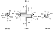
- FIG. 6 shows a flow cell including a detection unit 2, two branch inflow channels 31, 32, and two branch outflow channels 41, 42.
- the two branch inflow channels 31 and 32 are arranged symmetrically with respect to the detection unit center plane 22 of the detection unit 2.
- the liquid to be measured flowing into the flow cell 1 from the upstream pipe 5 passes through the inflow ports 301 and 302 from the branch inflow passages 31 and 32 and enters the detection unit 2, and from the detection unit 2 through the outflow ports 401 and 402, It joins downstream and flows into the downstream pipe 6 through the joining outflow passage 45.
- the number of outflow passages is not limited to two, and a single outflow passage similar to that of the conventional flow cell, a plurality of three or more as shown in FIG.
- the detection light 109 enters from the upstream end surface 201 of the detection unit and exits from the downstream end surface 202. Alternatively, the detection light 109 enters from the downstream end surface 202 of the detection unit and exits from the upstream end surface 201.
- the spread of the chromatogram is particularly small when the light intensity distribution of the detection light has the highest intensity at the center of the detection unit.
- the flow field in the detection unit has a large flow velocity at the center and a small flow velocity near the wall surface. Therefore, the sample molecule flows mainly in the center of the detection unit. Since the light amount distribution of the detection light is larger at the center than near the wall surface, the contribution to the detection concentration of the sample molecules flowing through the center of the detection unit is large. Therefore, the spread of the chromatogram is reduced.
- the vortex generated in the vicinity of the inlet in the detection unit is smaller than in the conventional example, and the spread of the chromatogram is reduced. As a result, the analysis accuracy of the liquid chromatograph is improved.
- a third embodiment of the present invention will be described with reference to FIG. According to this embodiment, the stagnation in the vicinity of the inlet in the detection unit is reduced.
- FIG. 7 shows a flow cell including a detection unit 2, two swirl flow inflow channels 33, 34, and two branch outflow channels 41, 42.
- the liquid to be measured that flows into the flow cell 1 from the upstream pipe 5 enters the detection unit 2 through the inflow paths 33 and 34 for the swirling flow, passes through the inflow ports 303 and 304, and branches out from the detection unit 2 through the outflow ports 401 and 402. It flows out into the channels 41 and 42, merges downstream thereof, flows through the merged outflow channel 45, and flows into the downstream pipe 6.
- the inflow directions of the two swirling flow inflow paths 33 and 34 are offset without intersecting with the center line 21 of the detection unit 2 and are arranged point-symmetrically with respect to the center line 21 of the detection unit 2.
- the number of outflow passages is not limited to two, and a single outflow passage similar to that of the conventional flow cell, a plurality of three or more as shown in FIG. 4, and the entire arrangement around the detection section shown in FIG. 5 may be taken.
- the detection light 109 enters from the upstream end surface 201 of the detection unit and exits from the downstream end surface 202. Alternatively, the detection light 109 enters from the downstream end surface 202 of the detection unit and exits from the upstream end surface 201.
- the flow that flows into the detection unit from the swirl flow inflow paths 33 and 34 becomes a jet due to the inertia of the liquid. Since the inflow directions of the swirl flow inflow paths 33 and 34 do not intersect with the center line 21 of the detection unit 2, the jets flowing from each of them swirl along the wall surface of the detection unit 2. Since the swirling jet flows along the wall surface inside the detection unit 2, the inertia loses and disappears at a short distance due to the friction. Therefore, the vortex generated with the jet is reduced. In addition, when there are two inflow channels, the vortex generated from one inflow channel reduces the vortex generated by the jet flowing from the other inflow channel. Get smaller. As a result, the time for sample molecules to escape from the vortex is reduced and the chromatogram spread is reduced.
- FIG. 8 is a flow cell including two or four swirl flow inflow channels 33, 34, 35, and 36 and a single outflow channel 4.
- the liquid to be measured that flows into the flow cell 1 from the upstream pipe 5 enters the detection unit 2 from the flow passages connected to the swirl flow inflow paths 33 and 34 and both ends of the detection unit 2 of 35 and 36, and from the detection unit 2 It flows out into one outflow channel 4 and flows into the downstream pipe 6.
- Each inflow direction is offset without intersecting with the center line 21 of the detection unit 2 and arranged symmetrically with respect to the center line 21 of the detection unit 2 as in the third embodiment of FIG. Yes.
- the vortex generated in the vicinity of the inlet in the detection unit is smaller than in the conventional example, and the spread of the chromatogram is reduced. As a result, the analysis accuracy of the liquid chromatograph is improved.
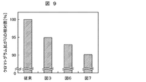
- FIG. 9 shows the simulation results of the chromatogram expansion of the conventional flow cell and the flow cell shown in FIGS. 3, 6 and 7 of the above embodiment.
- the index of the chromatogram spread is the half value width
- the relative value of the half value width of the flow cell shown in FIGS. 3, 6 and 7 is shown when the half value width of the conventional flow cell is 100%.
- the spread of the chromatogram is reduced as compared with the conventional flow cell.
Landscapes
- Physics & Mathematics (AREA)
- Spectroscopy & Molecular Physics (AREA)
- Health & Medical Sciences (AREA)
- Life Sciences & Earth Sciences (AREA)
- Chemical & Material Sciences (AREA)
- Analytical Chemistry (AREA)
- Biochemistry (AREA)
- General Health & Medical Sciences (AREA)
- General Physics & Mathematics (AREA)
- Immunology (AREA)
- Pathology (AREA)
- Optical Measuring Cells (AREA)
- Investigating Or Analysing Materials By Optical Means (AREA)
Abstract
液体クロマトグラフにおいて、フローセルによってクロマトグラムが拡がり、分析精度が低下する。 検出光の方向と被測定液の流れの方向が平行であり、検出部と流出路、検出部と流入路のそれぞれで流れの方向が変化するフローセルにおいて、以下の手段でクロマトグラムの拡がりを小さくする。第一に、複数の流出路41,42を配置し、流れの角と流出口との距離を短くする。第二に、検出部中心面22に対して線対称な複数の流入路31,32を配置し、検出部2に流入する噴流を衝突させる。第三に、流路方向が検出部中心線21と交わらない複数の流入路33,34を配置し、検出部2に流入する噴流を旋回させる。これらの構成を組み合わせることで、クロマトグラムの拡がりの小さいフローセルを得る。
Description
本発明は、フローセル,検出器、および液体クロマトグラフに関し、フローセルを流れる液体試料の吸光度を測定する液体クロマトグラフに関する。
液体クロマトグラフにおいて、分離カラムで分離したサンプルの検出に最も一般的に使用されているのは紫外吸収検出器である(非特許文献1)。吸光度は、ランベルト・ベールの法則(Lambert-Beer′s law)より、
A=εcl=logI0/I (1)
で表される。ここで、Aは吸光度、εはモル吸光係数、cはモル濃度、lは光路長、I0は入射光量、Iは透過光量である。式(1)より、吸光度Aは光路長lに比例する。また、吸光度測定の透過光量を測定する受光器のシグナルは受光量に比例し、ノイズは受光量の1/2乗に比例するため、S/N比は受光量の1/2乗に比例する。一方、受光器の受光量は照射面積に比例する。したがって、受光器のS/N比は、照射面積の1/2乗に比例する。以上より、吸光度測定において物質の検出に必要なS/N比を確保するには、ある程度以上の光路長と照射面積が必要である。
A=εcl=logI0/I (1)
で表される。ここで、Aは吸光度、εはモル吸光係数、cはモル濃度、lは光路長、I0は入射光量、Iは透過光量である。式(1)より、吸光度Aは光路長lに比例する。また、吸光度測定の透過光量を測定する受光器のシグナルは受光量に比例し、ノイズは受光量の1/2乗に比例するため、S/N比は受光量の1/2乗に比例する。一方、受光器の受光量は照射面積に比例する。したがって、受光器のS/N比は、照射面積の1/2乗に比例する。以上より、吸光度測定において物質の検出に必要なS/N比を確保するには、ある程度以上の光路長と照射面積が必要である。
液体クロマトグラフに用いられる配管の内径は0.1mm程度であり、このサイズでは、吸光度測定に必要な光路長と照射面積を得ることはできない。そこで、検出に必要な光路長と照射面積を確保するために、それらに応じた流路長と流路幅を持つフローセルと呼ばれる流路が用いられる。
特許文献1に、従来技術によるフローセル構造が記載されている。フローセルの流路は、検出光が当たる検出部と、上流配管から検出部に被測定液を流入させる流入路と、検出部から下流配管に被測定液を流出させる流出路からなる。検出部は3~15μlの容積,3~10mmの長さ,0.5~1.5mmの内径を持っている。また、検出光の方向と被測定液の方向が平行であり、検出部と流出路、検出部と流入路のそれぞれで流れの方向が大きく変化する。
特許文献2では、被測定液を渦流生成路を通して検出部に流入させる構成により、検出部内で渦流を生じさせることで流路断面における濃度を均一化させるフローセルが開示されている。このフローセルも、従来技術によるフローセルと同様に、検出光の方向と被測定液の流れの方向が平行であり、検出部と流出路、検出部と流入路のそれぞれで流れの方向が大きく変化する。
特許文献3,特許文献4,特許文献5では、複数の流入路により、検出部内に均一に被測定液を流入させるフローセルが開示されている。このフローセルは、検出光の方向と被測定液の流れの方向は異なり、検出部と流出路、検出部と流入路のそれぞれで流れの方向がほとんど変化しない。
津田孝雄、「化学セミナー クロマトグラフィー 第2版 分離のしくみと応用」、丸善、東京、1995.
本発明が開示しようとする課題は、検出光と被測定液の流れの方向が平行であり、検出部と流出路、検出部と流入路のそれぞれで流れの方向が変化する構成のフローセルにおいて、クロマトグラムの拡がりを低減することである。
特許文献1記載の従来技術のフローセルでは、流出路と検出部の接続部である流出口、および、流入路と検出部の接続部である流入口および流出口において、流れが淀む。淀みの中に入り込むサンプル分子は、入り込まないサンプル分子に比べて検出部に留まる時間が長いため、クロマトグラムが拡がる。
流出口付近の淀みは、流れ方向の変化のために生じる。検出光の向きと被測定液の流れの向きが同じ場合、検出部の端面は検出光が透過する面となる。したがって、流出口は、検出部の側面に配置し、検出部から流出路にかけて流れの方向を変えなければならない。流れの方向が変化する場合、流路の角付近で流速が遅くなり、流れが淀む。したがって、流路の角が流出口から遠いほど、サンプル分子が検出部から抜け出すのに時間がかかる。
一方、流入口付近の淀みは、流路幅が急激に拡大することで流れが流路壁面から剥離し、その結果として生じる渦によって起こる。渦に入り込んだサンプル分子は、分子拡散によってのみ渦から抜け出る。分子拡散による移動速度は、サンプル分子と溶媒の間の物性である拡散係数によって決まり、流れの速度には依存しない。したがって、渦の大きさが大きいほど、サンプル分子が渦から抜け出すのに時間がかかり、その結果、検出部から抜け出す時間も長くなる。
特許文献2記載のフローセルでは、流入口付近では渦流が生じるため、従来フローセルよりも流れの淀みは小さい。しかし、流出口は従来フローセルと同様の構成であるため、流出口付近の流れの淀みも従来と同程度である。
特許文献3,特許文献4,特許文献5記載のフローセルは、検出光の方向と被測定液の流れの方向が異なり、流入路と検出部の流れの方向が同一な構成である。流路幅が検出器よりも小さい流入路が検出部に複数本接続されているため、各流入口の間で渦が発生し、流れが淀む。
本発明の目的は、フローセルによるクロマトグラムの拡がりが小さくすることである。
本発明のフローセルは、検出光が照射される検出部と、検出部における試料の流れ方向と異なる方向に検出部に試料を流入させる流入部と、検出部における試料の流れ方向と異なる方向に検出部から試料を流出させる流出部とを備え、検出光の照射方向と検出部の試料の流れ方向が平行であるフローセルにおいて、流出部は、試料を検出部から複数方向へ流出する流路を有している。
本発明によって、フローセルによるクロマトグラムの拡がりが小さくなる。それによって、液体クロマトグラフの分析精度が向上する。
検出光の方向と被測定液の流れの方向が平行であり、検出部と流出路、検出部と流入路のそれぞれで流れの方向が変化するフローセルにおいて、以下の手段によってクロマトグラムの拡がりを小さくする。
第一の手段として、検出部内の流出口付近での流れの淀みを小さくするために、複数の流出路を配置し、流れが淀む流路角から流出口までの距離を短くする。これによって、サンプル分子が検出部から抜け出す時間が短くなる。
第二の手段として、検出部内の流入口付近での流れの淀みを小さくするために、検出部の中心に対して線対称な複数の流入路を配置し、流入路から検出部に流入する噴流を衝突させる。これによって、検出部の中心面に対して対称な流れが生じるために、従来のフローセルよりも渦が小さくなり、サンプル分子が渦から抜け出す時間が短くなる。
第三の手段として、検出部内の流入口付近での流れの淀みを小さくするために、流入方向が検出部の中心と交わらない流入路を複数配置し、流入路から検出部に流入する噴流によって旋回流を生じさせる。これによって、一つの旋回流で生じる渦を別の旋回流によって打ち消すために、従来よりも渦が小さくなり、淀みからサンプル分子が渦から抜け出す時間が短くなる。
第一,第二の手段、または、第一,第三の手段は組み合わせることも可能であり、それらの組み合わせによってさらにクロマトグラムの拡がりは小さくなる。
図1を用いて液体クロマトグラフの構成を説明する。液体クロマトグラフは、送液ポンプ101,サンプルインジェクタ102,分離カラム103,検出器104、それらを接続する配管105,検出部104の測定結果を記録する記録機106、を備えている。検出器104は、フローセル1,光源108,受光器107を有する。光源108から出射した検出光109が、フローセル1内を流れる被測定液を透過し、受光器107に受光されることで、被測定液の吸光度が測定される。
図2にクロマトグラム(吸光度の時間変化)の模式図を示す。本発明の目的は、記録機106に記録されるクロマトグラムの拡がりを、図2に示すように低減させることである。クロマトグラムの拡がりが低減することで、より微小量のサンプルの検出が可能であり、液体クロマトグラフの分析精度が向上する。
図3から図5を用いて、本発明における第一の実施例について説明する。
図3は、検出部2,1本の単一流入路3,2本の分岐流出路41,42,分岐流出路の下流の合流流出路45より構成されるフローセルである。上流配管5からフローセル1に流入する被測定液は、単一流入路3から流入口300を通って検出部2に入り、検出部2から流出口401,402を通って分岐流出路41,42に流出し、その下流で合流して合流流出路45を通って、下流配管6に流れ込む。検出光109は、検出部の上流側端面201から入射し、下流側端面202から出射する。もしくは、検出光109は、検出部の下流側端面202から入射し、上流側端面201から出射する。
この構成では、流出口が401,402の2箇所にあるため、流れの角から流出口までの距離が短い。その結果、角部から流出路までサンプル分子が移動する時間が短くなり、クロマトグラムの拡がりが小さくなる。流れの角と流出口との距離を最小にするには、流出路41,42の配置は、検出部中心面22に対して対称位置が好ましい。
図4は、3本の分岐流出路41,42,43が配置された構成である。流出路の数は3本に限らず、それ以上の本数の構成でもよい。
流出路が多くなるほど、流れの角と検出部内の流出口との距離が短くなるため、角部から流出路までサンプル分子が移動する時間が短くなる。流出路が3個以上配置される場合も、各流出路の配置は検出部2の中心線21に対して対称が望ましい。
図5は検出部2の周囲全てに全周流出路44を配置した構成である。図4に示した構成において、流出路の数を実質的に無限にしたものである。
本発明によれば、流れの角と流出口との距離が短くなることで、角部から流出路までサンプル分子が移動する時間が従来例と比べて小さくなり、クロマトグラムの拡がりが小さくなる。その結果、液体クロマトグラフの分析精度が向上する。
図6を用いて、本発明における第二の実施例について説明する。
図6は、検出部2,2本の分岐流入路31,32,2本の分岐流出路41,42で構成されるフローセルである。2本の分岐流入路31,32は検出部2の検出部中心面22に対して線対称に配置されている。上流配管5からフローセル1に流入する被測定液は、分岐流入路31,32から流入口301,302を通過して検出部2に入り、検出部2から流出口401,402を通過して、その下流で合流して合流流出路45を通って、下流配管6に流れ込む。流出路の数は2本に限らず、従来フローセルと同様の単一の流出路、図4に示したような3本以上の複数、図5に示した検出部周囲全ての配置をとってもよい。検出光109は、検出部の上流側端面201から入射し、下流側端面202から出射する。もしくは、検出光109は、検出部の下流側端面202から入射し、上流側端面201から出射する。
検出部内の流入口付近の淀みは、流路幅が急激に拡大することで流れが流路壁面から剥離して噴流となり、それに伴って渦が生じるために起こる。噴流が持続する長さが長いほど、渦は大きくなる。流入路が単一の従来フローセルでは、流入する噴流は検出部の壁面に衝突するまで消失しない。それに対して、本発明の構成では、分岐流入路31,32は検出部中心面22に対して線対称に配置されているため、それぞれから流入する噴流同士が検出部中心面22で衝突する。それによって、噴流は検出部中心面22で消失する。したがって、従来フローセルと比べて、噴流が維持する距離が短い。そのために、噴流に伴って生じる渦も小さくなる。結果として、サンプル分子が渦から抜け出す時間が短くなり、クロマトグラムの拡がりが小さくなる。
図6に示す流入路と流出路がともに検出部中心に対して対称な配置のフローセルでは、検出光の光量分布が検出部の中心が最も強度が高い場合に、特にクロマトグラムの拡がりが小さい。この構成では、検出部内の流れ場は、中心の流速が大きく、壁面近くの流速が小さい。そのため、サンプル分子は主に検出部の中心を流れる。検出光の光量分布は、壁面近くに比べて、中心の方が大きいため、検出部の中心を流れるサンプル分子の検出濃度への寄与が大きくなる。したがって、クロマトグラムの拡がりが小さくなる。
本発明によれば、検出部内の流入口付近に生じる渦が従来例と比べて小さくなり、クロマトグラムの拡がりが小さくなる。その結果、液体クロマトグラフの分析精度が向上する。
図7を用いて、本発明における第三の実施例について説明する。この実施例によって、検出部内の流入口付近の淀みが低減する。
図7は、検出部2,2本の旋回流用流入路33,34,2本の分岐流出路41,42で構成されるフローセルである。上流配管5からフローセル1に流入する被測定液は、旋回流用流入路33,34から流入口303,304を通って検出部2に入り、検出部2から流出口401,402を通って分岐流出路41,42に流出し、その下流で合流して合流流出路45を通って、下流配管6に流れ込む。2本の旋回流用流入路33,34の流入方向は検出部2の中心線21と交わらずオフセットしており、かつ検出部2の中心線21に対して点対称に配置されている。流出路の数は2本に限らず、従来フローセルと同様の単一の流出路、図4に示したような3本以上の複数、図5に示した検出部周囲全ての配置をとってもよい。検出光109は、検出部の上流側端面201から入射し、下流側端面202から出射する。もしくは、検出光109は、検出部の下流側端面202から入射し、上流側端面201から出射する。
旋回流用流入路33,34から検出部に流入する流れは、液体の慣性によって噴流となる。旋回流用流入路33,34の流入方向は検出部2の中心線21と交わらないため、それぞれから流入する噴流は検出部2の壁面に沿って旋回する。旋回する噴流は検出部2内部の壁面に沿って流れるために、その摩擦によって短い距離で慣性が失われ、消失する。そのために、噴流に伴って生じる渦が小さくなる。また、流入路が2本であるとき、一方の流入路から流入する噴流が、もう一方の流入路から流入する噴流によって生じる渦を低減させるために、流入路が1本の場合よりも渦は小さくなる。結果として、サンプル分子が渦から抜け出す時間が短くなり、クロマトグラムの拡がりが小さくなる。
図8を用いて、本発明における第四の実施例について説明する。図8は、検出部2,4本の旋回流用流入路33,34,35,36,単一流出路4で構成されるフローセルである。上流配管5からフローセル1に流入する被測定液は、旋回流用流入路33,34と、35,36の検出部2の両端部に接続する流路から検出部2に入り、検出部2から単一流出路4に流出し、下流配管6に流れ込む。それぞれの流入方向は、図7の第三の実施例と同様に、検出部2の中心線21と交わらずオフセットしており、かつ検出部2の中心線21に対して点対称に配置されている。
本発明によれば、検出部内の流入口付近に生じる渦が従来例と比べて小さくなり、クロマトグラムの拡がりが小さくなる。その結果、液体クロマトグラフの分析精度が向上する。
図9に従来フローセルと上記実施例の図3,図6,図7で示したフローセルのクロマトグラム拡がりのシミュレーション結果を示す。クロマトグラム拡がりの指標は半値幅とし、従来フローセルの半値幅を100%としたときの、図3,図6,図7で示したフローセルの半値幅の相対値を示している。いずれの実施例においても、従来フローセルよりもクロマトグラムの拡がりが低減していることがわかる。
1 フローセル
2 検出部
3 単一流入路
4 単一流出路
5 上流配管
6 下流配管
21 検出部中心線
22 検出部中心面
31,32 分岐流入路
33,34,35,36 旋回流用流入路
41,42,43 分岐流出路
44 全周流出路
45 合流流出路
101 送液ポンプ
102 サンプルインジェクタ
103 分離カラム
104 検出器
105 配管
106 記録機
107 受光器
108 光源
109 検出光
201 検出部上流側端面
202 検出部下流側端面
300,301,302 流入口
401,402 流出口
2 検出部
3 単一流入路
4 単一流出路
5 上流配管
6 下流配管
21 検出部中心線
22 検出部中心面
31,32 分岐流入路
33,34,35,36 旋回流用流入路
41,42,43 分岐流出路
44 全周流出路
45 合流流出路
101 送液ポンプ
102 サンプルインジェクタ
103 分離カラム
104 検出器
105 配管
106 記録機
107 受光器
108 光源
109 検出光
201 検出部上流側端面
202 検出部下流側端面
300,301,302 流入口
401,402 流出口
Claims (17)
- 検出光が試料に照射される検出部と、前記検出部における前記試料の流れ方向と異なる方向に前記検出部に前記試料を流入させる流入部と、前記検出部における前記試料の流れ方向と異なる方向に前記検出部から前記試料を流出させる流出部とを備え、前記検出光の照射方向と前記試料の流れ方向とが平行であるフローセルにおいて、
前記流出部は、前記試料を前記検出部から複数方向へ流出させる流路を有することを特徴とするフローセル。 - 請求項1において、
前記流出部の流路は、前記複数方向へ流出した前記試料をその後合流させるように構成されたことを特徴とするフローセル。 - 請求項2において、
前記検出部からの前記試料の流出方向は前記検出光の照射方向と直交することを特徴とするフローセル。 - 請求項2において、
前記試料は前記検出部から放射状に流出することを特徴とするフローセル。 - 請求項2において、
前記流入部は、前記試料を前記検出部の手前で一旦分岐させ、前記検出部で合流させる流路から構成されており、前記検出部への前記試料の流入方向が、前記検出部の端面の中心に対してオフセットし、点対称であることを特徴とするフローセル。 - 請求項1において、
前記複数方向へ流出する流路の方向が2方向であり、
該流路の方向は、前記検出部の中心面に対して対称であることを特徴とするフローセル。 - 請求項1において、
前記複数方向へ流出する流路の方向が3方向以上であり、
該流路の方向は、前記検出部の端面の中心に対して対称であることを特徴とするフローセル。 - 請求項7において、
前記試料は前記検出部から放射状に流出することを特徴とするフローセル。 - 請求項1において、
前記検出部からの前記試料の流出方向は前記検出光の照射方向と直交することを特徴とするフローセル。 - 請求項1において、
前記流入部は、前記試料を前記検出部の手前で一旦分岐させ、前記検出部で合流させる流路から構成されており、前記検出部への前記試料の流入方向が前記検出部の端面の中心と交差していることを特徴とするフローセル。 - 請求項10において、
前記検出部への前記試料の流入方向が、前記検出部の端面の中心と直交することを特徴とするフローセル。 - 請求項1において、
前記流入部は、前記試料を前記検出部の手前で一旦分岐させ、前記検出部で合流させる流路から構成されており、前記検出部への前記試料の流入方向が、前記検出部の端面の中心に対してオフセットし、点対称であることを特徴とするフローセル。 - 検出光が照射される検出部と、前記検出部における試料の流れ方向と異なる方向に前記検出部に前記試料を流入させる流入部と、前記検出部における前記試料の流れ方向と異なる方向に前記検出部から前記試料を流出させる流出部とを備え、前記検出光の照射方向と前記検出部の前記試料の流れ方向が平行であるフローセルにおいて、
前記流入部は、前記検出部の手前で前記試料を一旦分岐させ、前記検出部で合流させるように前記検出部の両端部に接続する流路から構成されており、前記検出部への前記試料の流入方向が、前記検出部の端面の中心に対してオフセットし、点対称であることを特徴とするフローセル。 - 検出光が試料に照射される検出部と、前記検出部に前記試料を流入させる流入部と、前記検出部から前記試料を流出させる流出部とを有するフローセル、
前記検出部に対して前記検出光を照射する光源、
前記検出部を通過した前記検出光を受光する受光器を備えた検出器において、
前記検出部を流れる前記試料の流れ方向と前記検出光の照射方向とが平行であり、
前記流入部では、前記検出部の前記試料の流れ方向と異なる方向に前記検出部に前記試料を流入させ、
前記流出部では、前記検出部の前記試料の流れ方向と異なる複数方向に前記検出部から前記試料を流出させることを特徴とする検出器。 - 請求項14において、
前記流出部では、前記複数方向へ流出した前記試料をその後合流させるように構成されたことを特徴とする検出器。 - 供給液を送液する送液ポンプと、
前記供給液に測定対象を混合させるインジェクタと、
該インジェクタから送られる試料を分離する分離カラムと、
前記分離カラムで分離された前記試料に検出光を照射し検出する検出器と、
前記検出器で検出された前記検出光に基づいて前記試料の測定結果を記録する記録機とを備えた液体クロマトグラフにおいて、
前記検出器は、前記検出光を照射する光源、前記検出光を受光する受光器、前記試料の流れ方向と前記検出光の照射方向とが平行であるように前記試料が流れる検出部と、前記検出部に前記試料を流入させる流入部と、前記検出部から前記試料を流出させる流出部とを有するフローセルを備え、
前記流入部は、前記検出部の前記試料の流れ方向と異なる方向に前記検出部に前記試料を流入させ、
前記流出部は、前記検出部の前記試料の流れ方向と異なる複数方向に前記検出部から前記試料を流出させることを特徴とする液体クロマトグラフ。 - 請求項16において、
前記流出部では、前記複数方向へ流出した前記試料をその後合流させるように構成されたことを特徴とする液体クロマトグラフ。
Priority Applications (1)
| Application Number | Priority Date | Filing Date | Title |
|---|---|---|---|
| US13/388,765 US20120127469A1 (en) | 2009-09-30 | 2010-06-18 | Flow cell, detector, and liquid chromatograph |
Applications Claiming Priority (2)
| Application Number | Priority Date | Filing Date | Title |
|---|---|---|---|
| JP2009225879A JP5047248B2 (ja) | 2009-09-30 | 2009-09-30 | フローセル,検出器、および液体クロマトグラフ |
| JP2009-225879 | 2009-09-30 |
Publications (1)
| Publication Number | Publication Date |
|---|---|
| WO2011039909A1 true WO2011039909A1 (ja) | 2011-04-07 |
Family
ID=43825763
Family Applications (1)
| Application Number | Title | Priority Date | Filing Date |
|---|---|---|---|
| PCT/JP2010/004072 Ceased WO2011039909A1 (ja) | 2009-09-30 | 2010-06-18 | フローセル,検出器、および液体クロマトグラフ |
Country Status (3)
| Country | Link |
|---|---|
| US (1) | US20120127469A1 (ja) |
| JP (1) | JP5047248B2 (ja) |
| WO (1) | WO2011039909A1 (ja) |
Families Citing this family (3)
| Publication number | Priority date | Publication date | Assignee | Title |
|---|---|---|---|---|
| JP2014032098A (ja) * | 2012-08-03 | 2014-02-20 | Hitachi High-Technologies Corp | 液体クロマトグラフ分析装置 |
| US10451593B2 (en) * | 2016-08-04 | 2019-10-22 | Aa Holdings, Ltd. | Detection system and method with nanostructure flow cell |
| JP6688514B2 (ja) * | 2016-12-27 | 2020-04-28 | 国立研究開発法人産業技術総合研究所 | 光学測定用フローセル |
Citations (2)
| Publication number | Priority date | Publication date | Assignee | Title |
|---|---|---|---|---|
| JPS49107792A (ja) * | 1973-02-19 | 1974-10-14 | ||
| JPS5555238A (en) * | 1978-10-20 | 1980-04-23 | Toshiba Corp | Flow cell |
Family Cites Families (9)
| Publication number | Priority date | Publication date | Assignee | Title |
|---|---|---|---|---|
| US3622795A (en) * | 1968-10-10 | 1971-11-23 | Coulter Electronics | Colorimetric fluid test apparatus having plural fluid sequential control |
| US4047892A (en) * | 1976-07-01 | 1977-09-13 | Phillips Petroleum Company | Liquid chromatographic analysis for styrene-butadiene monomers |
| JPS5852550A (ja) * | 1981-09-24 | 1983-03-28 | Hitachi Ltd | フロ−インジエクシヨン分析におけるゴ−ストピ−クの解消法 |
| US5116759A (en) * | 1990-06-27 | 1992-05-26 | Fiberchem Inc. | Reservoir chemical sensors |
| WO1994027146A1 (en) * | 1993-05-14 | 1994-11-24 | Coulter Corporation | Reticulocyte analyzing method and apparatus utilizing light scatter techniques |
| US5676830A (en) * | 1996-04-12 | 1997-10-14 | Wyatt Technology Corporation | Method and apparatus for reducing band broadening in chromatographic detectors |
| US6342948B1 (en) * | 1998-11-20 | 2002-01-29 | Waters Investments Limited | Dual pathlength system for light absorbance detection |
| JP2006524553A (ja) * | 2003-04-28 | 2006-11-02 | ボード オブ リージェンツ, ザ ユニバーシティ オブ テキサス システム | カテーテル画像化プローブ及び方法 |
| EP2664916B1 (en) * | 2007-04-02 | 2017-02-08 | Acoustic Cytometry Systems, Inc. | Method for manipulating a fluid medium within a flow cell using acoustic focusing |
-
2009
- 2009-09-30 JP JP2009225879A patent/JP5047248B2/ja not_active Expired - Fee Related
-
2010
- 2010-06-18 US US13/388,765 patent/US20120127469A1/en not_active Abandoned
- 2010-06-18 WO PCT/JP2010/004072 patent/WO2011039909A1/ja not_active Ceased
Patent Citations (2)
| Publication number | Priority date | Publication date | Assignee | Title |
|---|---|---|---|---|
| JPS49107792A (ja) * | 1973-02-19 | 1974-10-14 | ||
| JPS5555238A (en) * | 1978-10-20 | 1980-04-23 | Toshiba Corp | Flow cell |
Also Published As
| Publication number | Publication date |
|---|---|
| JP5047248B2 (ja) | 2012-10-10 |
| US20120127469A1 (en) | 2012-05-24 |
| JP2011075352A (ja) | 2011-04-14 |
Similar Documents
| Publication | Publication Date | Title |
|---|---|---|
| US20120323502A1 (en) | Flow volume measurement device and flow velocity measurement device | |
| CN102713564A (zh) | 光学流通池检测器 | |
| CN107247109A (zh) | 气相色谱仪分析系统和方法 | |
| JP5047248B2 (ja) | フローセル,検出器、および液体クロマトグラフ | |
| US20150062572A1 (en) | White cell for fluid detection | |
| US20180224408A1 (en) | Flow channel structure and measuring device for measurement target liquid | |
| CN111077083A (zh) | 一种变量程气相分子吸收池系统及吸收光谱仪 | |
| JPS63305233A (ja) | 分流型フロ−セル | |
| CN205235481U (zh) | 显色池气泡脱除装置以及连续流动分析设备 | |
| US5900152A (en) | Apparatus to reduce inhomogeneities in optical flow cells | |
| RU2015139400A (ru) | Способ и система для определения биологического ответа мишени на растворимое вещество-кандидат | |
| JP5590875B2 (ja) | 流量測定装置及び流速測定装置 | |
| CN211741050U (zh) | 一种变量程气相分子吸收池系统及吸收光谱仪 | |
| US20140083173A1 (en) | Fluid interface between fluid lines of differing cross-sectional area | |
| KR100926955B1 (ko) | 시차 굴절률 측정용 장치 | |
| CN204679411U (zh) | 光检测单元及使用该光检测单元的液相色谱分析装置 | |
| WO2014021099A1 (ja) | 液体クロマトグラフ分析装置 | |
| US4501969A (en) | Photometric apparatus and process | |
| CN207096187U (zh) | 气相色谱仪分析系统 | |
| US11255829B2 (en) | Chromatography system and a method therefor | |
| JP6750734B2 (ja) | フローセル及びそのフローセルを備えた検出器 | |
| Ren et al. | A microchip based Z-cell absorbance detector integrating micro-lenses and slits for portable liquid chromatography | |
| US20200200720A1 (en) | Optical detector flow cell for co2-based chromatography | |
| JP3314461B2 (ja) | 液体クロマトグラフ | |
| CN209927790U (zh) | 低流量液相色谱仪检测器用检测池 |
Legal Events
| Date | Code | Title | Description |
|---|---|---|---|
| 121 | Ep: the epo has been informed by wipo that ep was designated in this application |
Ref document number: 10820036 Country of ref document: EP Kind code of ref document: A1 |
|
| WWE | Wipo information: entry into national phase |
Ref document number: 13388765 Country of ref document: US |
|
| NENP | Non-entry into the national phase |
Ref country code: DE |
|
| 122 | Ep: pct application non-entry in european phase |
Ref document number: 10820036 Country of ref document: EP Kind code of ref document: A1 |